Arcade Top Skater Dlx Manual 1.TOPSKATE User
TOPSKATE TOPSKATE
2013-11-27
User Manual: Arcade Top Skater Dlx Manual
Open the PDF directly: View PDF ![]() .
.
Page Count: 107 [warning: Documents this large are best viewed by clicking the View PDF Link!]

OWNER’S MANUAL
SEGA ENTERPRISES, USA
MANUAL NO. 4201-6308-01
1ST PRINTING
MAY 1997
TM

Warranty
Your new Sega Product is covered for a period of 90 days from the date of shipment. This certifies
that the Printed Circuit Boards, Power Supplies and Monitor are to be free of defects in workman-
ship or materials under normal operating conditions. This also certifies that all Interactive Control
Assemblies are to be free from defects in workmanship and materials under normal operating condi-
tions. No other product in this machine is hereby covered.
Sellers sole liability in the event a warranted part described above fails shall be, at its option, to
replace or repair the defective part during the warranty period. For Warranty claims, contact your
Sega Distributor.
Should the Seller determine, by inspection that the product was caused by Accident, Misuse, Ne-
glect, Alteration, Improper Repair, Installation or Testing, the warranty offered will be null and void.
Under no circumstances is the Seller responsible for any loss of profits, loss of use, or other dam-
ages.
This shall be the exclusive written Warranty of the original purchaser expressed in lieu of all other
warranties expressed or implied. Under no circumstance shall it extend beyond the period of time
listed above.
INTRODUCTION OF THE OWNERS MANUAL
GENERAL PRECAUTIONS
1. PRECAUTIONS TO BE HEEDED FOR OPERATION
2. NAME OF PARTS
3. ACCESSORIES
4. ASSEMBLY AND INSTALLATION
5. PRECAUTIONS TO BE HEEDED WHEN MOVING MACHINE
6. CONTENTS OF GAME
7. EXPLANATION OF TEST AND DATA DISPLAY
7-1 POWER SUPPLY UNIT AND COIN METER
7-2 TEST MODE
7-3 MEMORY TEST
7-4 INPUT TEST
7-5 OUTPUT TEST
7-6 SOUND TEST
7-7 C.R.T. TEST
7-8 GAME ASSIGNMENTS
7-9 COIN ASSIGNMENTS
7-10 BOARD SETTING
7-11 BOOKKEEPING
7-12 BACKUP DATA CLEAR
8. MAINTENANCE OF MECH UNIT
8-1 ADJUSTMENT AND REPLACEMENT OF SLIDE VOLUME
8-2 ADJUSTMENT AND REPLACEMENT OF CURVING VOLUME
8-3 GREASING
8-4 REPLACEMENT OF HAZARD PREVENTIVE PARTS
9. COIN SELECTOR
10. PROJECTOR
10-1 CLEANING THE SCREEN
10-2 MITSUBISHI MONITOR
11. REPLACEMENT OF FLUORESCENT LAMP AND LAMPS
11-1 REPLACEMENT OF FLUORESCENT LAMP
11-2 REPLACEMENT OF LAMPS
12. PERIODIC INSPECTION TABLE
13. TROUBLESHOOTING
13-1 REPLACEMENT OF FUSES
14. GAME BOARD
14-1 REMOVING THE IC BOARD
14-2 COMPOSITION OF THE GAME BOARD
15. DESIGN RELATED PARTS
16. PARTS LIST
17. WIRING CODE COLOR TABLE
18. WIRING DIAGRAMS
1
2~3
4~6
7
8
9-19
20
21~25
26~39
27
28
28
29~30
29~30
31
31
32
33~35
36~37
38
39
40~42
40
41~42
42~44
45
46~47
48~51
48
49~51
52
52
52
53
54~55
55
56
56
57
58~59
60
103
XXX
TABLE OF CONTENTS
1
SPECIFICATIONS
Installation space: 106.5 in.(L) x 46 in.(W)
Height: 89 in.
Weight: Approx. 963 lbs.
Power maximum current: 7 Amp AC 120V 60 Hz
MONITOR: 50 INCH PROJECTION DISPLAY
SEGA ENTERPRISES, LTD., has for more than 30 years been supplying various innovative and
popular amusement products to the world market. This Owners Manual is intended to provide
detailed descriptions together with all the necessary installation, game settings and parts ordering
information related to the TOP SKATE, a new SEGA product.
This manual is intended for those who have knowledge of electricity and technical expertise, espe-
cially in ICs, CRTs, microprocessors, and circuit boards. Read this manual carefully to acquire
sufficient knowledge before working on the machine. Should there be a malfunction, non-technical
personnel should under no circumstances touch the interior system. Should the need arise, contact
our main office, or the closest branch office listed below.
SEGA ENTERPRISES, INC. (USA)
Customer Service
45133 Industrial Drive
Fremont, CA 94538
Phone 415-802-1750
Fax 415-802-1754
7:30 am - 4:00 pm, Pacific Standard Time
Monday thru Friday
INTRODUCTION OF THE OWNERS MANUAL

2
General Precautions
Follow Instructions: All operating and use instructions should be followed.
Attachments: Do not use attachments not recommended by the product manufacturer as they may cause hazards.
Accessories: Do not place this product on an unstable cart, stand, tripod, bracket, or table. The product may fall,
causing serious injury to a child or adult, and serious damage to the product. Use only with a cart, stand, tripod, bracket, or
table recommended by the manufacturer, or sold with the product. Any mounting of the product should follow the
manufacturer’s instructions, and should use only mounting accessories recommended by the manufacturer.
Moving the Product: This product should be moved with care. Quick stops, excessive force, and uneven surfaces
may cause the product to overturn.
Ventilation: Slots and openings in the cabinet are provided for ventilation, to ensure reliable operation of the product
and to protect it from overheating; these openings must not be blocked or covered. The openings should never be blocked by
placing the product in a built-in installation such as a bookcase or rack unless proper ventilation is provided or the
manufacturer’s instructions have been adhered to.
Power Sources: This product should be operated only from the type of power source indicated on the marking label.
If you are not sure of the type of power supply to your location, consult your local power company. For products intended
to operate from battery power or other sources, refer to the operating instructions.
Grounding or Polarization: This product is equipped with a three-wire grounding-type plug, a plug having a third
(grounding) pin. This plug will only fit into a grounding-type power outlet. This is a safety feature. If you are unable to
insert the plug into the outlet, contact your electrician to replace your obsolete outlet. Do not defeat the safety purpose of the
grounding-type plug.
Power Cord Protection: Power-supply cords should be routed so that they are not likely to be walked on or pinched
by items placed upon or against them, paying particular attention to cords at plugs, convenience receptacles, and the point
where they exit from the product.
Overloading: Do not overload wall outlets, extension cords, or integral convenience receptacles as this can result in
a risk of fire or electric shock.
Object and Liquid Entry: Never push objects of any kind into this product through openings as they may touch
dangerous voltage points or short-out parts that could result in a fire or electric shock. Never spill liquid of any kind on the
product.
Servicing: Do not attempt to service this product yourself as opening or removing covers may expose you to danger-
ous voltage or other hazards. Refer all servicing to qualified service personnel.
Damage Requiring Service: Unplug this product from the wall outlet and refer servicing to qualified service person-
nel under the following conditions:
a) If the power cord or plug is damaged;
b) If liquid has been spilled, or objects have fallen into the product;
c) If the product has been exposed to rain or water;
d) If the product does not operate normally when following the operating instructions. Adjust only those controls that
are explained in the operating instructions. An improper adjustment of other controls may result in damage and will
often require extensive work by a qualified technician to restore the product to its normal operation;
e) If the product has been dropped or damaged in any way;
f) When the product exhibits a distinct change in performance; this indicates a need for service.
Replacement Parts: When replacement parts are required, be sure the service technician has used replacements parts
specified by the manufacturer or that have the same characteristics as the original part. Unauthorized substitutions may
result in fire, electric shock, or other hazards.

3
Safety Check: Upon completion of any service or repairs to this product, ask the service technician to perform safety
checks to determine that the product is in proper operating condition.
Heat: The product should be situated away from heat sources such as radiators, heat registers, stoves, or other prod-
ucts (including amplifiers) that produce heat.
Lithium Battery- Dispose of batteries only in accordance with the battery manufacturer’s recommen-
dations. Do not dispose in an open flame condition, since the battery may explode.
Cleaning: When cleaning the monitor glass, use water or glass cleaner and a soft cloth. Do not apply chemicals such
as benzine, thinner, etc.
Location: This an indoor game machine, DO NOT install it outside. To ensure proper usage, avoid installing indoors
in the places mentioned below:
• Places subject to rain/water leakage, or condensation due to humidity;
• In close proximity to a potential wet area;
• Locations receiving direct sunlight;
• Places close to heating units or hot air;
•In the vicinity of highly inflammable/volatile chemicals or hazardous matter;
• On sloped surfaces;
• In the vicinity of emergency response facilities such as fire exits and fire extinguishers;
• Places subject to any type of violent impact;
• Dusty places.
INSTALLATION PRECAUTIONS
• Verify the amperage of the branch circuit outlet before plugging in the power plug. Do not over-
load the circuit.
• Avoid using an extension cord. If one is required, use an extension cord of type SJT, 16/3 AWG
rated min. 120 VAC, 7A.
• Moving this unit requires a minimum clearance (of doors, etc.) of 32” (W) by 77” (H).
• For the operation of this machine, secure a minimum area of 32” (W) by 42”(D).
REGULATORY A PPROVALS
This game has been tested and found to comply with the Federal Communications Commission Rules.
This device complies with Part 15 of the FCC Rules. Operation is subject to the following two conditions: (1) This
device may not cause harmful interference, and (2) this device must accept any interference received, including interference
that may cause undesired operation.
This game has been tested and listed by Underwriters Laboratories, Inc., to ANSI/UL22.
LISTED
UL
®
5K92
AMUSEMENT MACHINE
4
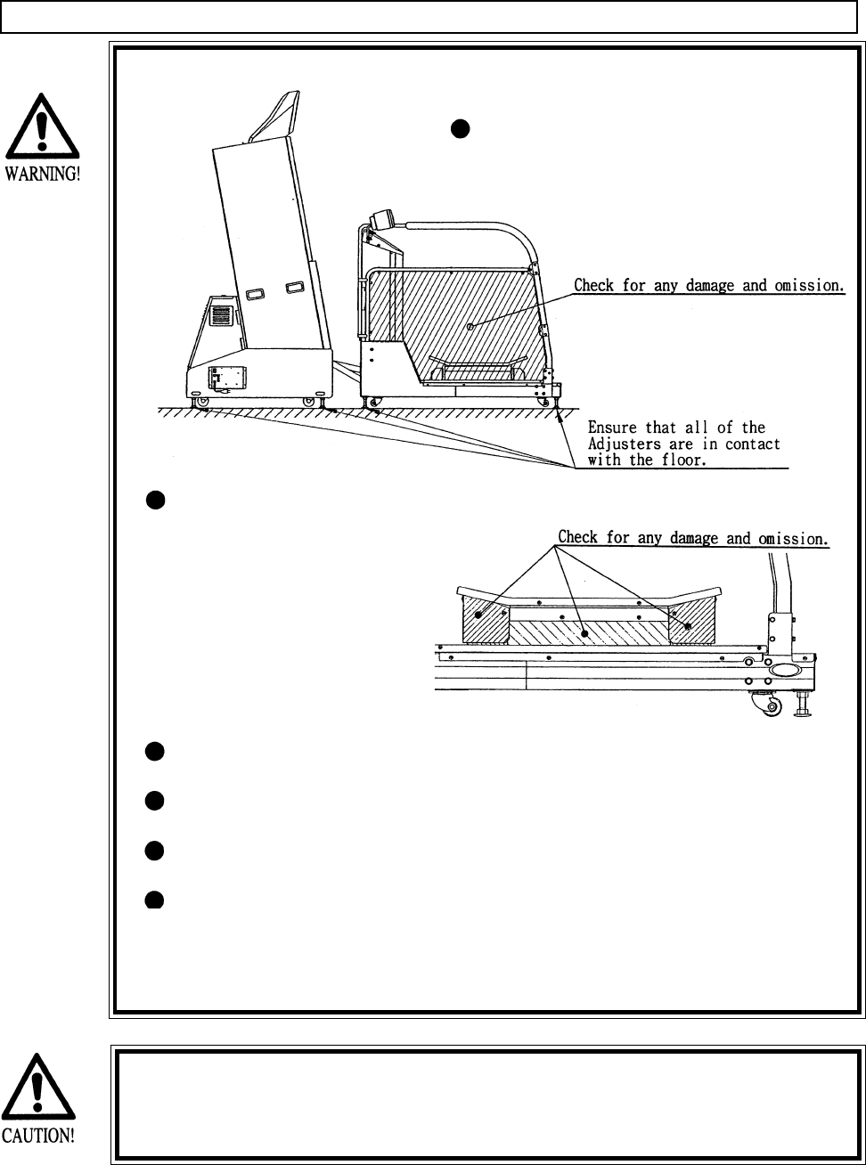
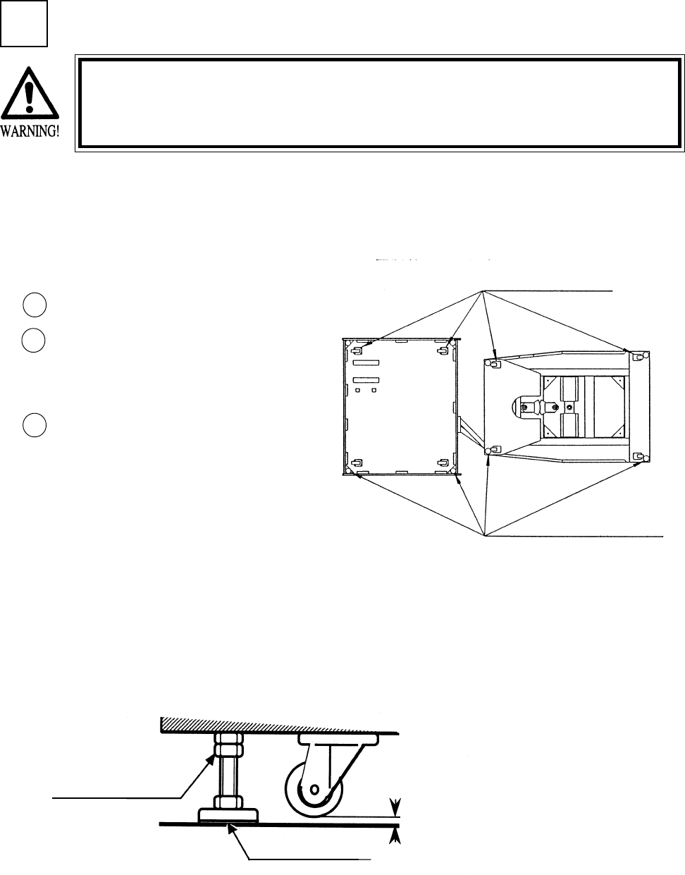
In order to avoid accidents, check the
following before starting the operation:
Check if all of the adjusters are in
contact with the surface. If they are
not, the cabinet can move and cause
an accident.
Check to see if hazard
preventive parts are
damaged or omitted.
Operating the product
with the hazard preven-
tive parts as is left in an
irregular status will
cause accidents.
Do not put any heavy item on this product. Placing any heavy item on the
product can cause a falling down accident or parts damage.
Do not climb on the product. Climbing on the product can cause falling
down accidents. To check the top portion of the product, use a step.
To avoid electric shock, check to see if door & cover parts are 508.5
To avoid electric shock, short circuit and or parts damage, do not put the
following items on or in the periphery of the product:
Flower vases, flower pots, cups, water tanks, cosmetics, and receptacles/
containers/vessels containing chemicals and water.
1 . PRECAUTIONS TO BE HEEDED FOR OPERATION
PRECAUTIONS TO BE HEEDED FOR OPERATION BEFORE STARTING THE OPERATION
This product allows the game to be played by operating the SKATE BOARD. In order to prevent
accidents, be sure to comply with the following points before and during operation.
To avoid injury, be sure to provide sufficient space by considering the
potentially crowded situation at the installation location. Insufficient instal-
lation space can cause the player to come into contact with or hit the
others and result in injury or trouble.
5
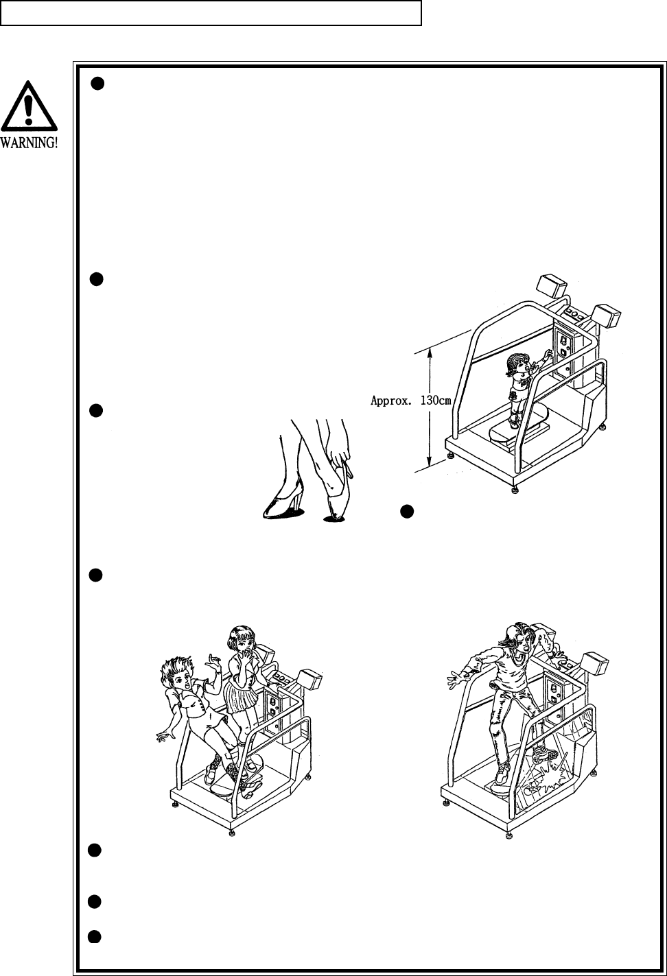
PRECAUTIONS TO BE HEEDED DURING OPERATION
To avoid injury and trouble, be sure to constantly give careful attention to the behavior and manner of the
visitors and players.
To avoid injury and accidents, those who fall under the following catagories are
not allowed to play the game.
> Intoxicated persons.
> Pregant women or those who are in the likelihood of pregnancy.
> Those who need assistance such as the use use of apparatus when walking.
> Those who have high blood pressure or a heart condition.
> Those who have experienced muscle convulsion or loss of conciousness when
exposed to intensive light stimulus due to watching television, playing video
games or water surface flickering.
> Persons susceptible to motion sickness.
> Persons whose actions runs counter to the product’s warning displays.
The player should be able to get on the
skate board and hold on firmly to the
safety bar. To avoid falling down accidents,
instruct those who are shorter than 51
inches not to play, as the height of the
saftey bar is approximately 51 inches.
Instruct those who
wear high heel shoes to
refrain from playing the
game by explaining that
playing game with high-
heeled shoes is very
likle to cause poten-
tially hazardous situa-
tion.
To avoid injury from potential falling
down accidents, be sure to that only
one person is allowed to play at a time.
Do not allow players to put any
heavy items or beverages on the
product. Falling items can cause
accidents and spilled beverages
can cause electric shock.
To avoid electric shock and short circuit, do not allow customers to put hands
and fingers or extraneous matter in the openings of the product or small open-
ings in or around the doors.
To avoid falling down and injury resulting from falling down, immediately stop the
customer’s leaning against or climbing on the product, etc.
To avoid electric shock and short circuit, do not allow the customers to unplug
the power plug without justifiable reason.
6
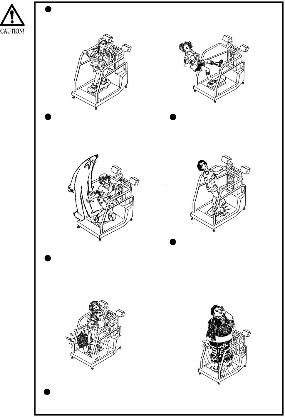
Instruct the player to hold firmly to the Saftey Bar during game. Caution
the customers who are most likely to cause injury by playing without
holding the Safety Bar, for example.
To avoid injury, do not allow
persons other than the player
access to the mechanism base
during game play.
Instruct the player to play by
standing on both feet. Standing
on one leg to play can cause
injury.
Instruct the player not to put
baggages, etc. on the mechanism
base to avoid damaging such
items.
Regarding this product, the
weight of the player is limited to
330 lbs. To avoid machine dam-
age and injury due to machine
damage, playing by those who
are as heavy as 330 lbs. or
heavier is strictly prohibited.
Immediately stop violent acts such as hitting and kicking the product. Such
violent acts can cause parts to be damaged or falling down, resulting in injury
due to fragments and falling down.
7
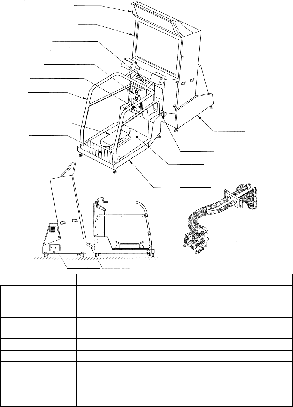
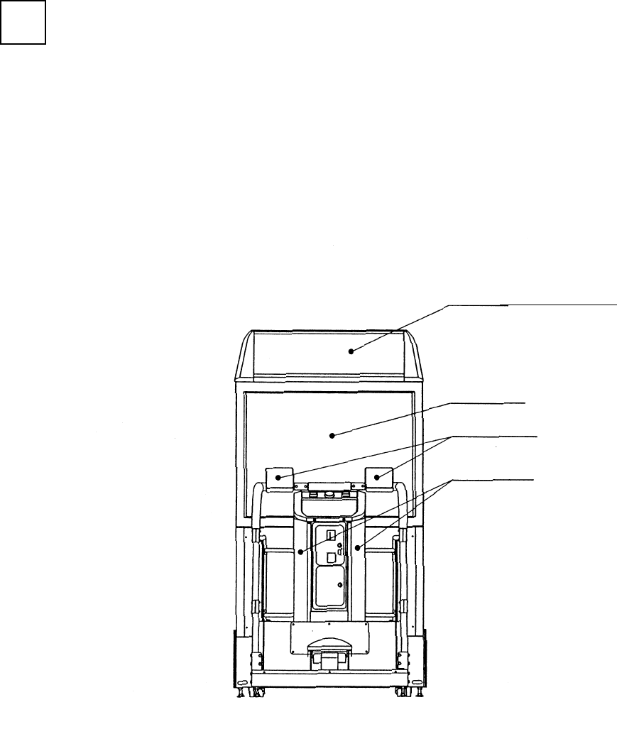
2 . NAME OF PARTS
PTV
REAR CABI
BILLBOARD
GAME SPECIFICATIONS
REAR CABINET
PTV
WHEN ASSEMBLED
REAR CABINET
PTV BASE/BILLBOARD
WIDTH LENGTH HEIGHT WEIGHT
DURING SHIPPING
963 LBS.
158.5 LBS.
263 LBS.
33 LBS.
508.5 LBS.
387 LBS.
FIG.2 OVERVIEW
CONTROL PANEL
CASHBOX DOOR
COIN CHUTE DOOR
SKATE BOARD
CAUTION MAT
ASSY TUBE
PTV BASE
SAFETY BAR
MECHANISM BASE
ASSY TUBE
AC UNIT
ASSY TUBE
BILLBOARD
PTV BASE
PTV 462 LBS.
748 LBS.
1597 LBS.
All measurements are in inches
63” X 44.5” X 64”
55” X 37.5” X 77”
54” X 48” X 43.5”
46” X 18” X 12”
38” X 58” X 56”
46” X 22” X 67”
47” X 41” X 31.5”
47” X 108” X 90”
8
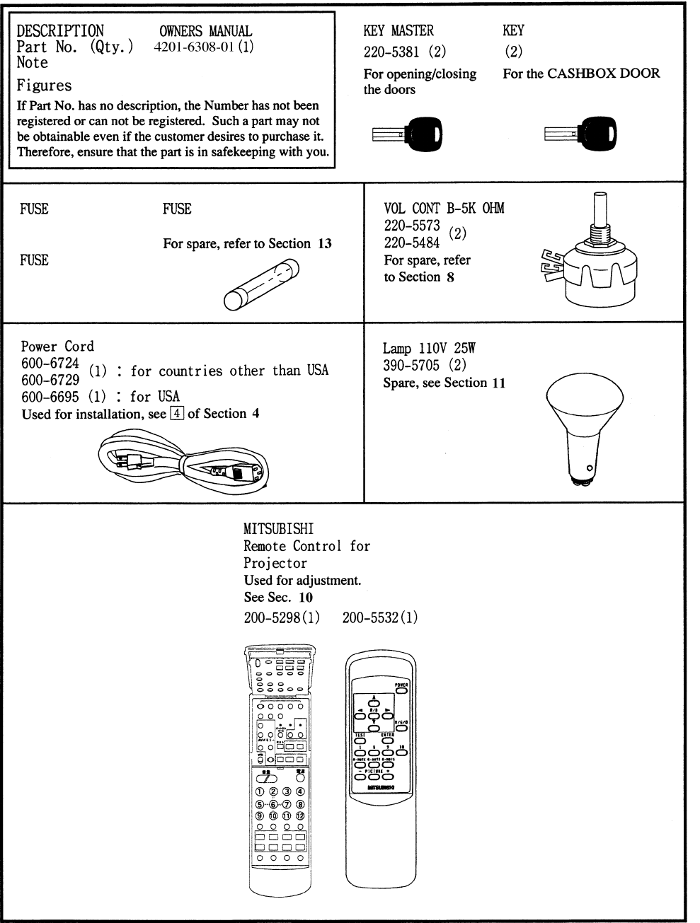
3 . ACCESSORIES
local purchase only
4 A slow blow
2@5 A slow blow
7 A slow blow
2 A slow blow
9
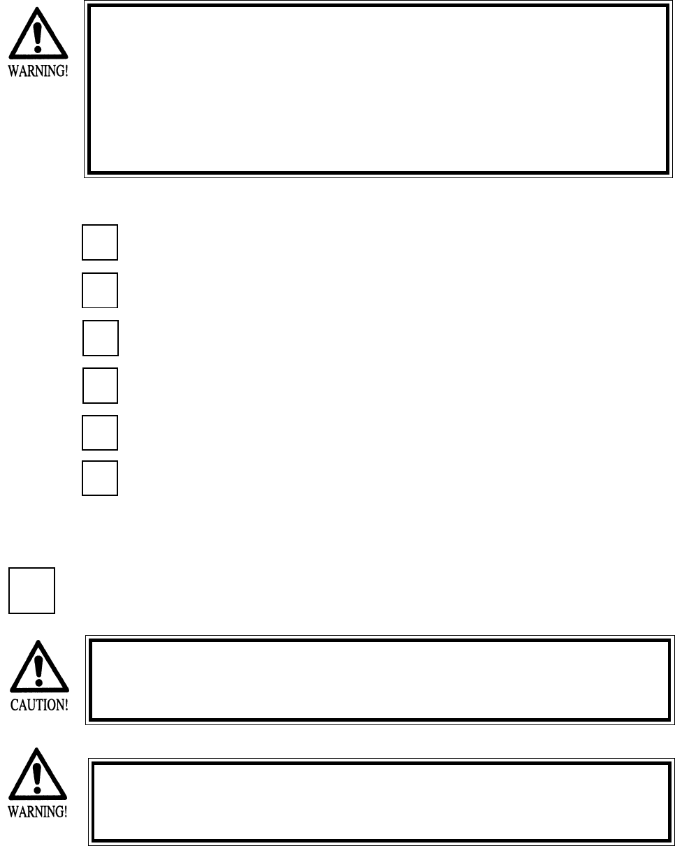
4 . ASSEMBLING AND INSTALLATION
Note that the tools such as a phillips screwdriver and wrench for M16 hexagon bolt w/24 mm width
across flats are required for the assembly work.
When carrying out the assembly work, follow the procedure in the following 6-item sequence:
ASSY OF PTV
WIRING CONNECTIONS BETWEEN CABINETS
SECURING IN PLACE (ADJUSTER ADJUSTMENT)
POWER SUPPLY
TURNING POWER ON
ASSEMBLING CHECK
Assembling should be performed as per this manual. Since this is a
complex machine, erroneous assembling may cause damage to the
machine, or malfunctioning to occur.
When assembling, be sure to perform work by plural persons.
Depending on the assembly work, there are some cases in which
performing the work by a single person can cause personal injury or
parts damage.
1
2
3
4
When installing the billboard, it is difficult to carry out work by one
person. To perform work properly and safely, be sure work is per-
formed by at least two people.
To perform work safely and securely, be sure to prepare a step
which is in a secure and stable condition. Not using a step or using
an unstable step can cause a violent falling down accident.
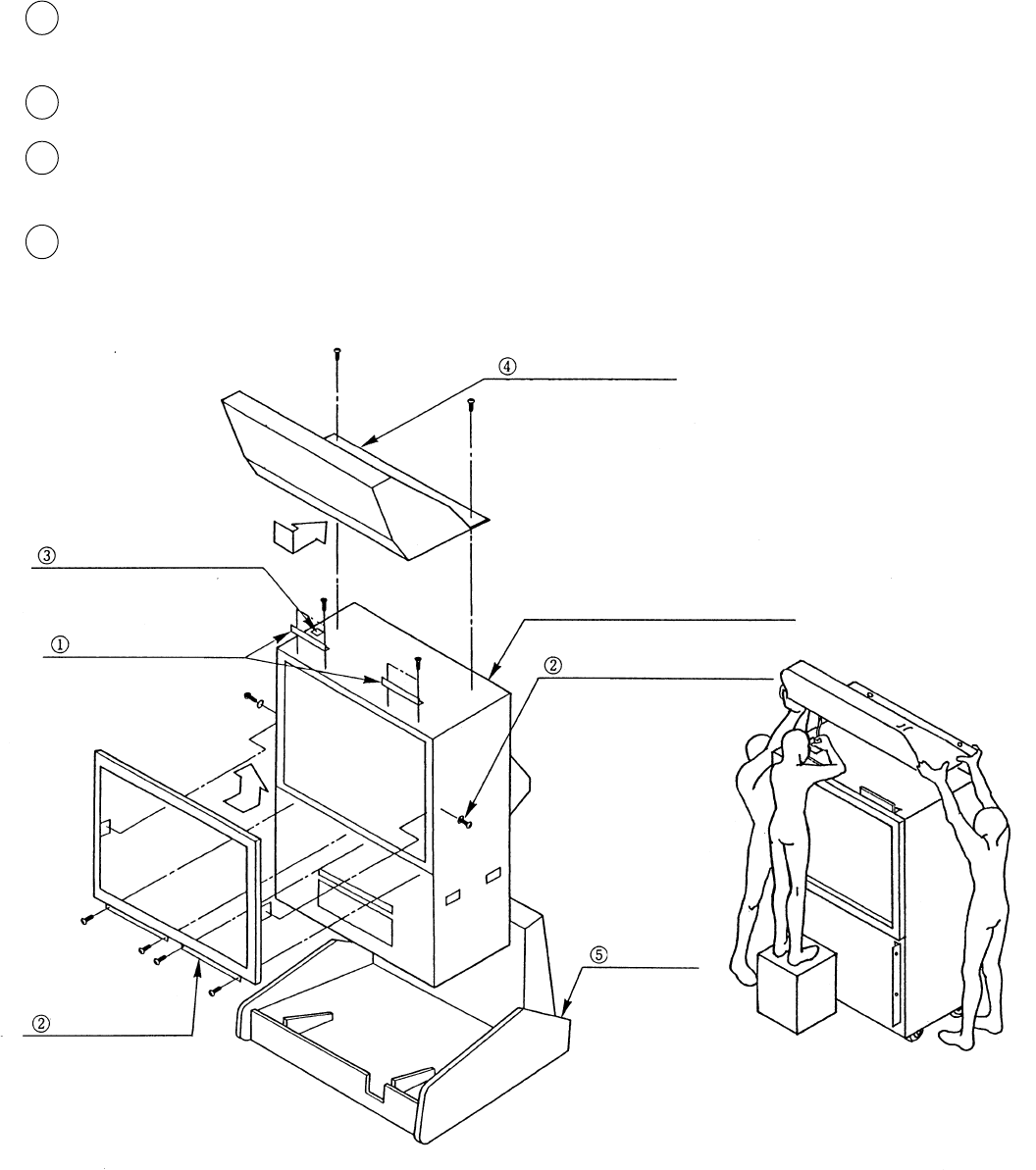
1 ASSY OF PTV
6
5
10
By using the specified screws, secure the 2 Mask Holders t o the Projection Display ceiling.
(Fig. 4.1a)
Insert the TV Mask from the underside as shown and secure with a total of 6 screws.
While supporting the Billboard by 2 persons, another person using a step is to insert the Bill-
board Connector into the Terminal Board of Projection Display ceiling. (Fig. 4.1b)
Insert the Billboard From the front as shown and secure with 2 screws (Fig. 4.1a)
FIG. 4.1a
1
2
3
4
BILLBOARD
BILLBOARD’S Connector
PROJECTION DISPLAY
MASK HOLDER
TV MASK
PTV BASE
SCREW (2), M5x25
SCREW (4), M5X20
FIG. 4.1b
w/flat & spring washers
One each on both sides
using flat washer, chrome
SCREW (2), M5x16
FLAT HEAD SCREW
M4x14 (2) for each
w/flat & spring washers, black
11
In order to prevent accidents during assembly
work, have all of the leg adjusters of the PTV
Base make contact with the surfaces to secure
the PTV Base.
5
6
7
8
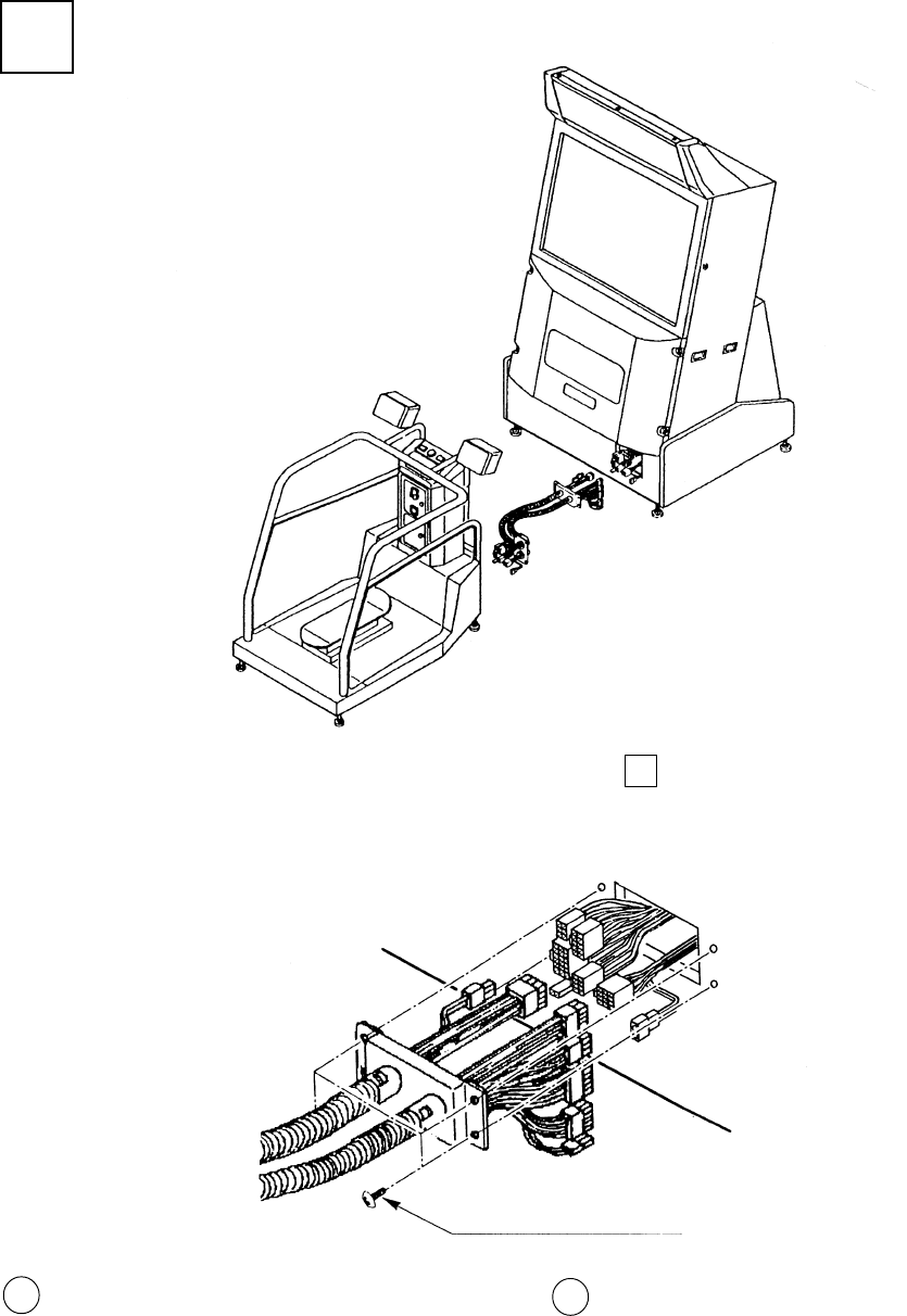
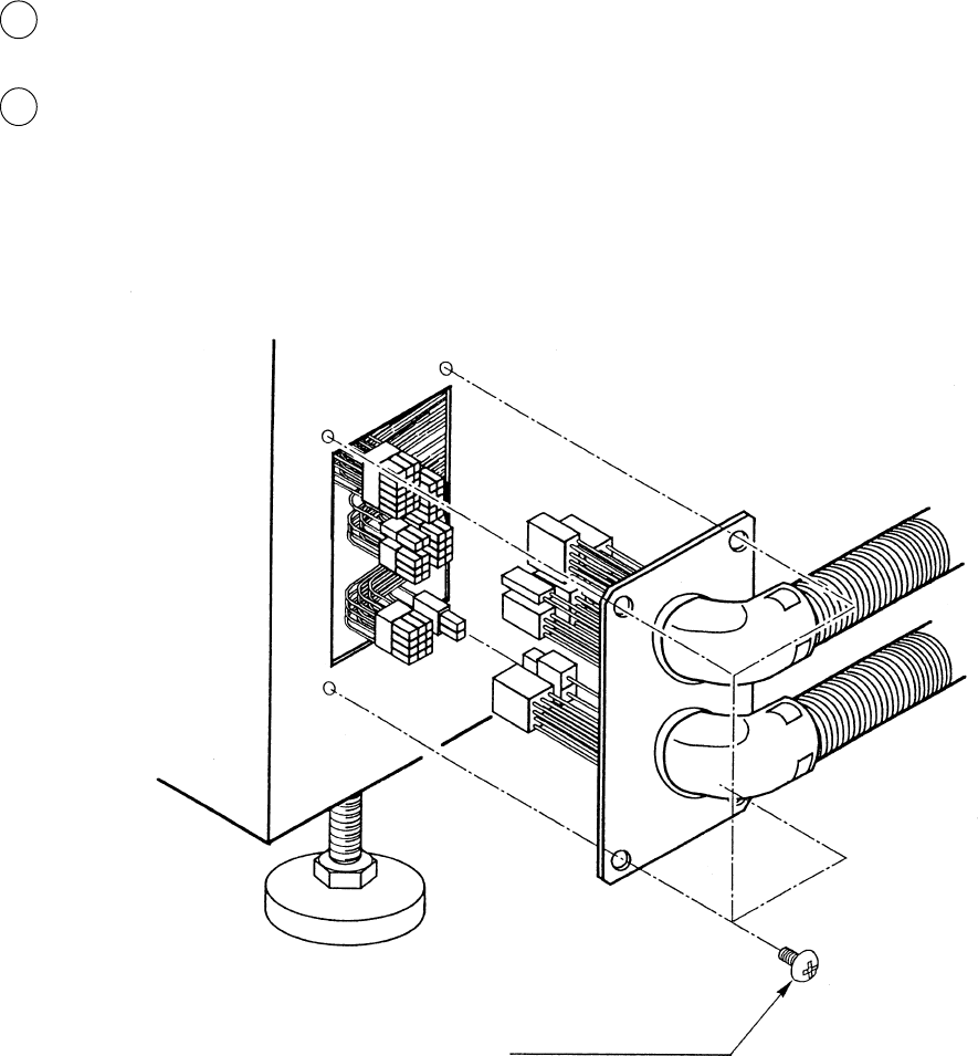
Connect the wires wired to the PTV Base to the PTV Connector Panel. Insert the wiring connectors, each of
which wire covering is red, green, and blue, to the corresponding one of R.G.B. terminals as per connector
panel display inside the PTV, and insert the remianing wire connector to the SYNC terminal. The
connector’s insertion angle is predetermined. Inserting the connector in a forcible manner will damage the
connector. Check for the correct inserting direction and then insert the connector. After insertion of the
connector, turn the connector’s ring clockwise to lock the connection.
The connector panel has 3p white connector in addition to the connectors displayed as R.G.B. and SYNC.
Connect the wiring coming from the PTV Base power supply unit to the 3p white connector.
CONTROL PANEL
CONTROL PANEL
Fig. 4.1d
Fig. 4.1c
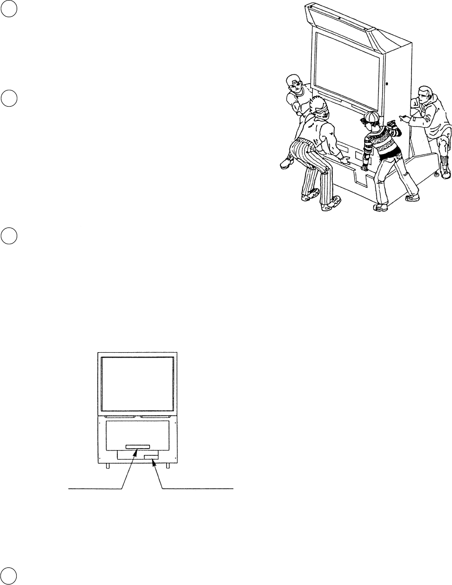
Mount the assembled PTV on the PTV Base.
After mounting the PTV, move it to the rear part
of the PTV Base. When performing this work, be
sure to use 4 or more persons.(Fig. 4.1c)
12
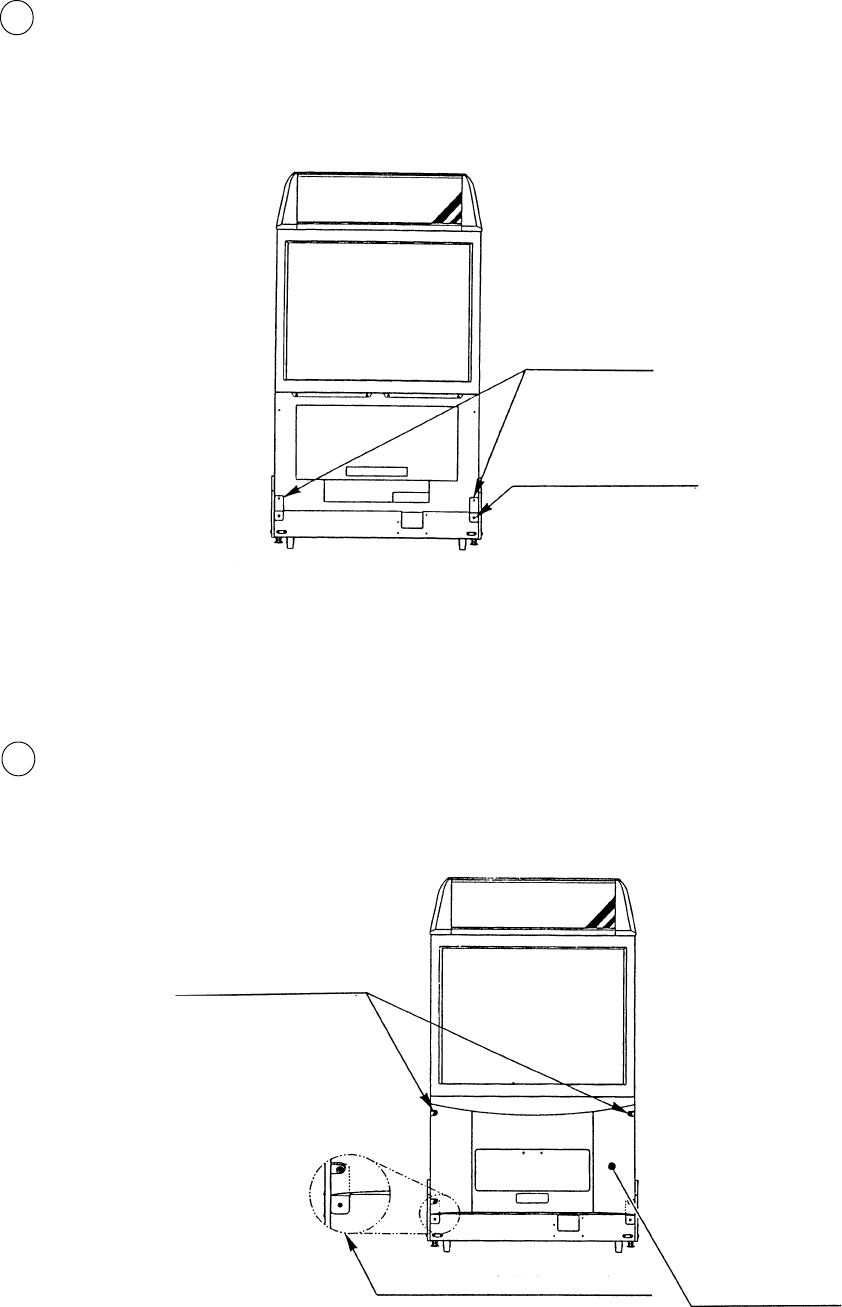
Temporarily fasten the PTV Holders to the PTV
Base with a screw for each Holder (Fig. 4.1e)
9
10 Secure the Front Panel to the front of the PTV
with 4 screws. At this time, by using the under-
side 2 screws, tighten together with the PTV
Holder.
(Fig. 4.1f)
PTV HOLDER
TRUSS SCREW
FRONT PANEL
TRUSS SCREW
Tighten together with the
PTV Holder
(4) chrome M5x25, using
flat washer
(1) for each M5x25,
chrome
Fig. 4.1e
Fig. 4.1f
13
The ASSY TUBE’s box side is to the Front
Cabinet. Connect all of the wiring connectors
coming from the Front Cabinet and the box side
wiring connectors. Be sure to connect the connec-
tors of identical color and number of pins.
Install the ASSY TUBE to the Front Cabinet which is assembled as per 1 and the Rear Cabinet, and perform wiring
connection in between both cabinets.
Secure the box to the Front Cabinet with 4 screws.
at this time, be very careful so that wires are not
caught and damaged.
(Fig. 4.2b)
Fig. 4.2b
Fig. 4.2a
2 WIRING CONNECTIONS BETWEEN THE CABINETS
REAR CABI
ASSY TUBE
TRUSS SCREW
M4x16, chrome
12
14
3
4
Connect all of the Rear Cabinet side Wiring Connectors and ASSY Tube Wiring Connectors. Ensure that connec-
tors of identical color and number of pins are connected with each other.
By using the 4 screws, secure the ASSY Tube Plate parts to the Rear Cabinet. At this time, use care so that wirings
are not caught and damaged. (Fig. 4.2c)
Fig. 4.2c
TRUSS SCREWS (4)
M4x8, chrome
15
SECURING IN PLACE (ADJUSTER ADJUSTMENT)
Move the machine to the installation position.
Cause all of the leg adjusters to make contact
with the floor. By using a wrench, make
adjustments in the height of the leg adjusters to
ensure that the machine's position is level.
After making adjustments, fasten the leg
adjuster nut upward and secure the height of the
leg adjuster.
This machine has 8 each of casters and adjusters (FIG. 3. 2 a). When the installation position is determined, cause
the adjusters to come into contact with the floor directly, make adjustments in a manner so that the casters will be
raised approximately 5mm. from the floor and make sure that the machine position is level.
Be sure to have all the Adjusters make contact with the surface. Un-
less the Adjusters come into contact with the surface, the Cabinet
can move of itself, causing an accident.
LEG ADJUSTER
3
3
2
1
1/4” INCH
LEVELERS (8) total
CASTERS (8) total
Fig. 4.3a
Fig. 4.3b
FASTEN UPWARDS

16
POWER SUPPLY
Ensure that the Main SW is OFF.
Fig. 4.4a
4
1
The AC unit is mounted on the left side of Front Cabinet DX. The AC Unit incorporates the Main SW, Earth Terminal
and Inlet. Firmly insert the Power Plug into the Socket Outlet and the other side of the plug to the Inlet. Turn the Main
SW ON to turn power ON.
Ensure that the power cord is not exposed on the surface (passage,
etc.). If exposed, they can be caught and are susceptible to damage.
If damaged, the cord can cause an electric shock or short circuit.
Ensure that the wiring position is not in the customer's passage way
or the wiring has protective covering.
17
TURNING POWER ON
5
To turn power on, turn the AC Unit’s Main SW on.
The Billboard’s Fluorescent Lamp lights up and images will be outputted on the projector. The lamps on the right
sides of the Coin Chute Tower alternate lighting up by halves.
Background music (BGM) is outputted during ADVERTISE from the speaker. However, this BGM is not emitted if
“No BGM output during ADVERTISE” is set. Since the Skate Board is locked unless the game is started, it can not be
moved in the right/left directions.
Images will be outputted
BGM is outputted
Lamp lights up
Fluorescent Lamp lights is on
Fig. 4.5a
18
In the TEST MODE, ensure that the assembly has been made correctly and IC BD is satisfactory (refer to Section 6).
In the test mode, perform the following test:
MEMEORY TEST
IC 09 GOOD IC 10 GOOD IC 11 GOOD
IC 12 GOOD IC l5 GOOD IC 16 GOOD
IC 79 GOOD IC 80 GOOD IC 81 GOOD
IC 82 GOOD IC 83 GOOD IC 84 GOOD
IC 88 GOOD IC 89 GOOD
PRESS TEST BUTTON TO EXIT
INPUT TEST
CURVING 80H
SLIDE 80H
JUMP FRONT OFF
JUMP TAIL OFF
START OFF
SELECT LEFT OFF
SELECT RIGHT OFF
COIN CHUTE#1 OFF
COIN CHUTE#2 OFF
SERVICE (ON BOARD) OFF
TEST(ON BOARD) OFF
SERVICE OFF
TEST OFF
PRESS TEST BUTTON TO EXIT
OUTPUT TEST
START LAMP OFF
SELECT LEFT OFF
SELECT RIGHT OFF
LAMP 1 ON
LAMP 2 OFF
LAMP 3 OFF
LAMP 4 OFF
LAMP 5 OFF
LAMP 6 OFF
PRESS TEST BUTTON TO EXIT
Selecting the INPUT TEST on the menu screen in the test
mode to display the screen on which each SW and Volume is
tested. Press each switch. (To check the Coin SW, insert a
Coin from the inlet with the Coin Chute Door being opened.)
If the display beside each switch is ON, the switch and wiring
connection are satisfactory. Check the display of each Volume
value. The Volume could have an irregularity caused by
differences between machines and vibration during transporta-
tion. Set the Volume values by referring to Section ?
In the output test mode, carry out lamp test to ascertain that
each lamp lights up satisfactorily.
Selecting the MEMORY TEST on the test mode menu
screen causes the on-board memory to be tested automati-
cally. The game board is satisfactory if the display beside
each IC No. shows GOOD.
ASSEMBLING CHECK
4
19
C.R.T. TEST 1/2
RED
GREEN
BLUE
WHITE
PRESS TEST BUTTON TO CONTINUE
In the TEST mode menu, selecting C.R.T. TEST allows the
screen (on which the projector is tested) to be displayed.
Although the projector adjustments have been made at the
same time of shipment from the factory, color deviation,
etc., may occur due to the effect caused by geomagnitism,
the location building’s steel frames and other game ma-
chines in the periphery. By watching the test mode screen,
make judgement as to whether an adjustment is needed. If it
is neccessary, adjust the projector by refering to Section 9.
In the TEST mode, selecting SOUND TEST causes the
screen, on which sound related BD and wiring connec-
tions are tested, to be displayed. be sure to check if the
sound is satisfactorily emitted from each of speaker and
the sound volume is appropriate.
SOUND TEST
SE : ( 0 )
BGM : ( 0 )
>EXIT
SELECT WITH SERVICE BUTTON
PRESS TEST BUTTON TO EXIT
Perform the above inspections also at the time of monthly inspection.
C.R.T. TEST 2/2
PRESS TEST BUTTON TO CONTINUE
20
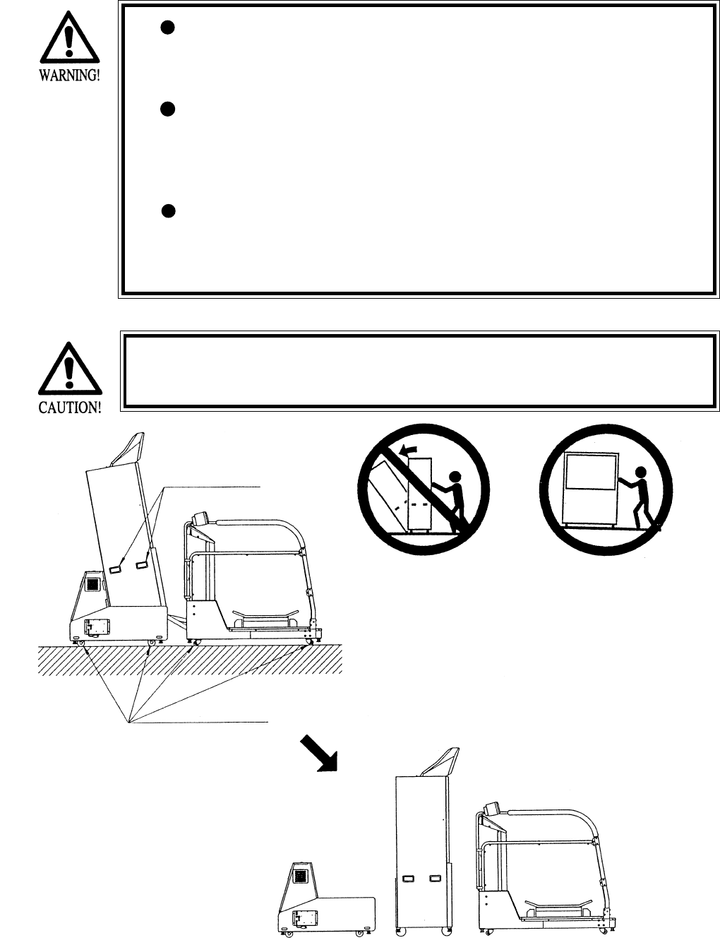
When moving the machine, be sure to pull out the plug from
the power supply. Moving the machine with the plug as is
inserted can damage the power cord and cause a fire or elec-
tric shock.
When moving the machine on the floor, retract the Adjusters
and ensure that Casters make contact with the floor. During
transportation, pay careful attention so that Casters do not
tread power cords. Damaging the power cords can cause an
electric shock and/or short circuit.
When lifting the cabinet, be sure to hold the catch portions or
bottom part. Lifting the cabinet by holding other portions can
damage parts and installation portions, due to the empty
weight of the cabinet, and cause personal injury.
Use care when handling glass made parts. When the glass is dam-
aged, fragments of glass can cause injury
5 . PRECATIONS TO BE HEEDED WHEN MOVING THE MACHINE
Caster
On level surfaces, move the machine by causing
the casters to make contact with the surfaces.
Do not push the PTV from the rear side. Pushing the PTV
from the rear side can cause the PTV to fall down. Push it
from the side.
Where there are steps (or step like differences
in grade), move the machine by seperating
into each unit.
Where to hold
21
The following explanations apply to the case the product is functioning statisfactorily. Should there be any moves
different from the following contents, some sort of faults may have occurred. Immmediatly look into the cause of
the fault and eliminate the cause thereof to ensure satisfactory operation
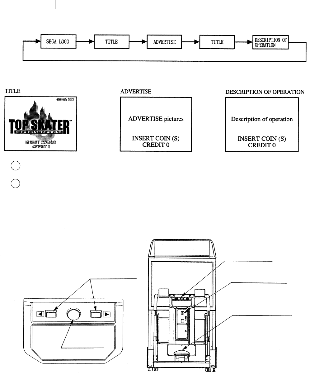
6 . CONTENTS OF GAME
2
1Get on the Skate Board (Foot Controller).
The Coin Chute Tower is located in the center of the Cabinet. Insert one play worth of coins to have the Start
Button light up. Press the Start Button to display the Course Select Screen. When in the Course Select Mode,
credits are not displayed. The maximum number of credits countable at a time is 9. Coins inserted after count-
ing 9 credits are not counted or rejected.
The on screen ADVERTISE before the commencement of game is comprised of the following:
HOW TO PLAY
During ADVERTISE LOOP, a total of 12 Lamps on both sides of the Coin Chute Tower are always flasing
Control Panel
Coin Chute Tower
Skate Board
(Foot Controller)
Select Button
Start Button
22
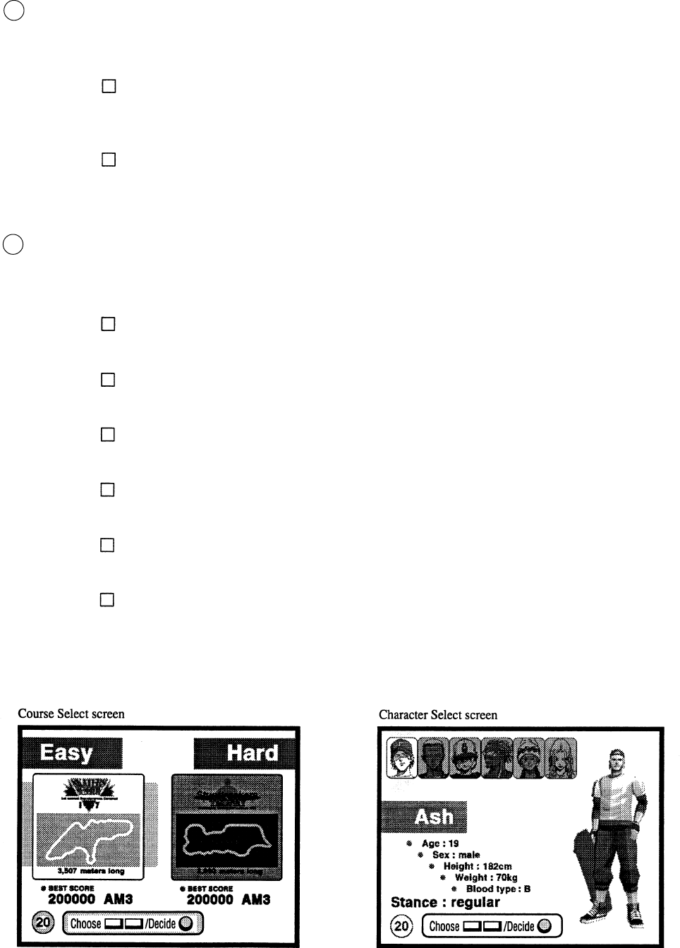
Decide the course to display the Character Select Screen. At this time, also, the Select Button and Start Button
altenately light up. Use the Select Button to choose and press the Start Button to decide the selection.
The course Select Screen allows the play course (event) to be selected. On the Select Screen, the Select Button
and Start Button alternately light up. Use the Select Button to choose the course and decide (the selection) with
the Start Button.
SKATERS SESSION (NOVICE):
This is the beginner’s course in the daytime mainly comprised of the Jumping Board and Half
Pipe.
STUNTTRACKERS TROPHY (EXPERT)
The skilled player’s course in the night mainly comprised of complex elements as rails, etc. in
addition to the Jumping Board and Half pipe.
Ash
A born skater, an unyeilding type.
Keith
A man of few words and a cool type. He is an avid fan of Skate Board and bass instruments.
Kenta
A self-concieted boy who likes Skate Boarding and outshining others.
J
An audacious, rough and powerful type.
Cookie
An attractive female skater whose technique is comparable with that of a man.
Jill
An attractive skater who is cool and sexy.
4
3
23
When the character is decided, the game starts. The “FOOT CONTROLLER IS UNLOCKED” message is
displayed and after the display is finished, the Skate Board is unlocked. Then, Skate Board slide operation can be
performed.
6
The Course Select Screen and Character Select Screen display the Remaining Time for selection on the lower left
part. Failing to press the Select Button within the time limit automatically decides the NOVICE Course and Ash
for the Character. While the Select Mode is displayed, all of the lamps on both sides of Coin ChuteTower are off.
5
In the similar manner as in the actual Skate Board, the Board can be turned in the desired direction by inclining
it. Furthermore, sliding the Skate Board allows for even more sharp turns.
Backward inputting while running allows for high jumping (OLLIE) and forward inputting, low jumpng
(NOLLIE).
Curving (inclining) Input Sliding (swing) Input
Backward and forward inputting
24
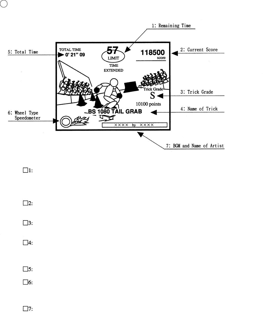
During game, the folowing screen is displayed.
5
Remaining Time
When 0 is displayed, the game is over.
Passing the checkpoint allows TIME EXTENDED to be displayed under the Remaining Time.
Current Score
Displays the total points of trick scored up to the present.
Trick Grade
Displays the difficulty level of the trick applied (6 catagories, i.e.,S~E) and the score.
Name of Trick
Displays the name of trick applied.
When failing to accomplish the trick, TRICK MISS is diplayed in the center of the screen.
Total Time
Wheel Type Speedometer
The faser the running speed is, the faster the wheel’s revolution.
Furthermore, as the speed nears the maximum, the flame will blow up from the wheel.
BGM and Name of Artist
Displays the name of the BGM being played, and the name of Artist who is singing.
In the Course, a checkpoint is set. Passing the checkpoint within the time limit allows the remaining time to be
extended, and game play can be continued. Also, note that earning the Time Bonus scattered in the course
enables you to extend the remaining time.
25
This product is aimed at earning high score by applying trick(s). Basically, the player can apply the trick at
three places, i.e., Jumping Board, Bank (Half Pipe) and Rail (Handrail).
HOW TO APPLY RAIL TRICKS
Jumping on to such rail shaped portion as the handrail enables you to apply the SLIDE based trick.
Lamps on both sides of Coin Chute Tower light up and flash in the manner matching the trick.
HOW TO APPLY BANK (HALF PIPE) TRICK
The BANK TRICK occurs when you come out of the BANK. Inputting the Foot Controller at the very
moment you come out of the BANK aloows the varied type of trick to be applied The faser you come out
from the BANK and closer the coming-out angle is to the vertically, the higher the difficulty level (6
catagories, i.e., S~E) of trick will be. in case of BANK, there will be no TRICK MISS.
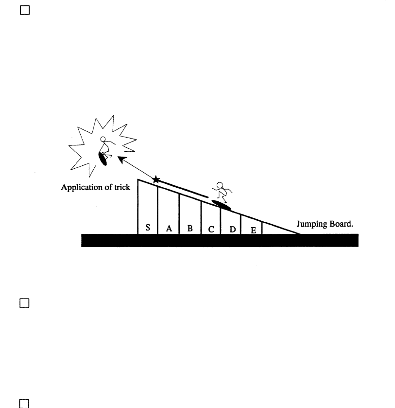
APPLYING THE JUMP TRICK:
The Jump trick is applied by inputting the Foot Controller on the Jump Board. Due to variation of input-
ting, the type of tricks will vary. The closer the inputting position is to the edge of the Jumpin Board, the
higher the difficulty level of the trick (6 catagories, i.e., S~E) will be. Inputting the Foot Controller after
passing the Jumping Board results in a Trick Miss.
When the remaining time comes to an end in the middle of Course or each course is cleared completly, the
game is over.
When the game is completly foinished, the total score of the trick(s) and the Bonus Score based on the
remaining time when reaching the finisheing line are comprehensively added, and thus evaluation in 6
catagories, i.e., S~E is performed.
If total score ranks 20th or higher, the player can enter his/her nameas a record holder.
After the game is finished, the Skate Board is Locked.
After finishng one game, if one play worth of credits or more still remain, the PRESS THE START BUTTON
message will be displayed

26
By operating the switch unit, periodically perform the tests and data check. When installing
the machine initially or collecting cash, or when the machine does not function correctly,
perform checking in accordance with the explanations given in this section. The following
shows tests and modes that should be utilized as applicable.
INSTALLATION
OF MACHINE
7 - 5
2. In the INPUT TEST mode, check each SW and VR.
3. In the OUTPUT TEST mode, check each of lamps.
4. In the MEMORY TEST mode, check ICs on the IC Board.
Choose MEMORY TEST in the MENU mode to allow the
MEMORY test to be performed. In this test, PROGRAM
RAMs, ROMs, and ICs on the IC Board are checked.
Periodically perform the following:
1. MEMORY TEST
2. Ascertain each setting.
3. In the INPUT TEST mode, test the CONTROL device
4. In the OUTPUT TEST mode, check each of lamps.
1. In the INPUT TEST mode, check each SW and VR.
2. Adjust or replace each SW and VR.
3.If the problem can not be solved yet, check the CONTROL’s moves.
In the PROJECTOR ADJUSTMENT mode, check to see if the
PROJECTOR adjustment is appropriately made.
1. MEMORY TEST
2. In the SOUND TEST mode, check the sound related ROMs.
Check such data as game play time and histogram to adjust the
difficulty level, etc
1. Check to see that each setting is as per standard setting made
at the time of shipment.
PERIODIC
SERVICING
MEMORY
PROJECTOR
DATA CHECK
CONTROL
SYSTEM
7 - 9, 7 - 10
7 - 5
7 - 6
7 - 3, 7 - 4
7 - 3, 7 - 4
7 - 9, 7 - l0
7 - 6
When the machine is installed, perform the following:
IC BOARD
7 - 5
8
TABLE 7 EXPLANATION OF TEST MODE
7 - 8
7 - 7
7 - 12
8
7 . EXPLANATION OF TEST AND DATA DISPLAY
ITEMS DESCRIPTION SECTIONS
27
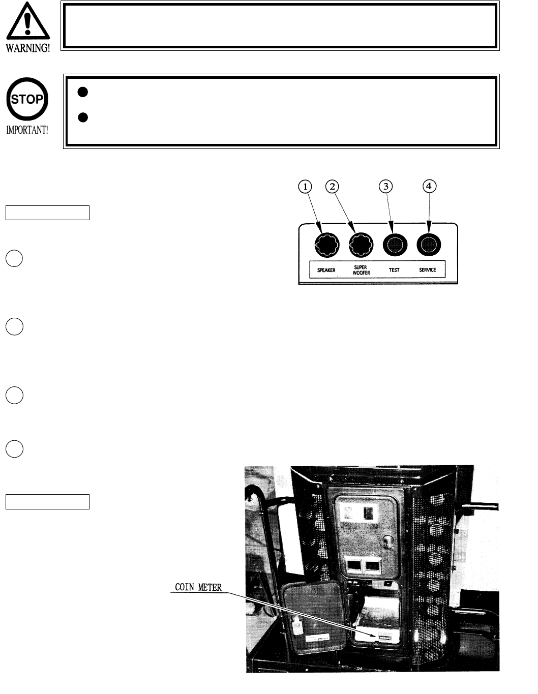
Open COIN CHUTE DOOR, and the switch unit shown appears. The function
of each switch is as follows:
7 - 1 SWITCH UNIT AND COIN METER
Never touch places other than those specified. Touching places not
specified can cause electric shock and short circuit.
Adjust to the optimum sound volume by considering the environmental
requirements of the installation location.
If the COIN METER and the game board are electrically disconnected,
game play is not possible.
SOUND VOLUME
Controls the speaker volume
of the right/left speakers on the
coin chute tower.
SUPER WOOFER VOLUME
Controls the sound volume of the
super woofer underneath the coin
chute tower.
TEST BUTTON (TEST SW)
For the handling of the TEST BUTTON,
refer to the section on test mode.
SERVICE BUTTON (SERVICE SW)
Gives credits without registering on the coin
meter.
2
1
3
4
SWITCH UNIT
COIN METER
Fig. 7.1
Photo 7.1 COIN METER
Open Cash Box Door and the
Coin Meter will appear. The
Coin Meter counts the
number of coins inserted
28
This mainly checks if the operation of the game BD is accurate, and allows for COIN
ASSIGNMENTS/GAME ASSIGNMENTS setting and Projector adjustments.
7 - 2 TEST MODE
7 - 3 MEMEORY TEST
The MEMORY TEST mode is for checking the
on-BD memeory IC functioning.
“GOOD” is displayed for normal ICs and “BAD”
is displayed for abnormal ICs
When the test is completed, if the
display is as shown left, it is
satisfactory.
After finishing the test, pressing the
TEST BUTTON allows the
MENU MODE to return on the
screen.
MEMEORY TEST
IC 09 GOOD IC 10 GOOD IC 11 GOOD
IC 12 GOOD IC l5 GOOD IC 16 GOOD
IC 79 GOOD IC 80 GOOD IC 81 GOOD
IC 82 GOOD IC 83 GOOD IC 84 GOOD
IC 88 GOOD IC 89 GOOD
PRESS TEST BUTTON TO EXIT
SELECTION OF TEST ITEMS
FIG. 7.2 TEST MENU
FIG. 7.3 MEMEORY TEST
Push the TEST BUTTON to cause the follow-
ing TEST MENU to appear:
By pushing the SERVICE BUTTON, bring the
“>” mark to the desired item and press the
TEST BUTTON. This will select the item’s
test.
After the test is complete, move the “>” mark
to “EXIT” and press the TEST BUTTON to
return to game mode.
3
1
2
TEST MODE
MEMEORY TEST
INPUT TEST
OUTPUT TEST
SOUND TEST
C.R.T.
GAME ASSIGNMENTS
COIN ASSIGNMNETS
BOARD SETTING
BOOKKEEPING
BACKUP DATA CLEAR
>EXIT
SELECT WITH SERVICE BUTTON
AND PRESS TEST BUTTON
IF THE TEST TIME FOR THE MEMORY TEST EXCEEDS 5 MINUTES THE IC BOARD MAY BE DEFECTIVE.

29
By pressing each switch, if the display on the righthand side
of the name of each switch changes to ON from OFF, the
SW and the wiring connections are satisfactory.
Open the COIN CHUTE DOOR and insert a coin from the
COIN ENRTY to check the COIN CHUTE SW.
In the INPUT test, pressing the TEST BUTTON simulta-
neously causes the menu to return to the screen.
When INPUT TEST is selected, the MONITOR will show the following, allowing you to watch the status of
each switch and the value of each V.R. of the cabinet to be viewed
On the screen, periodically check the status of each switch & V.R.
Choose OUTPUT TEST to cause the following lower screen to appear. In this test,
check the status of each lamp.
This mode allows each lamp to be tested automatically.
Approximately every other second, the display at the
right of the name of lamp changes from OFF to ON in
order. When ON is displayed, if the corresponding lamp
is lit, it is satisfactory.
Press the test Button to return to the MENU MODE.
INPUT TEST
CURVING 80H
SLIDE 80H
JUMP FRONT OFF
JUMP TAIL OFF
START OFF
SELECT LEFT OFF
SELECT RIGHT OFF
COIN CHUTE#1 OFF
COIN CHUTE#2 OFF
SERVICE (ON BOARD) OFF
TEST (ON BOARD) OFF
SERVICE OFF
TEST OFF
PRESS TEST BUTTON TO EXIT
OUTPUT TEST
START OFF
SELECT LEFT OFF
SELECT RIGHT OFF
LAMP1 ON
LAMP2 OFF
LAMP3 OFF
LAMP4 OFF
LAMP5 OFF
LAMP6 OFF
PRESS TEST BUTTON TO EXIT
7 - 4 INPUT TEST
FIG. 7.4a INPUT TEST
FIG. 7.5a OUTPUT TEST
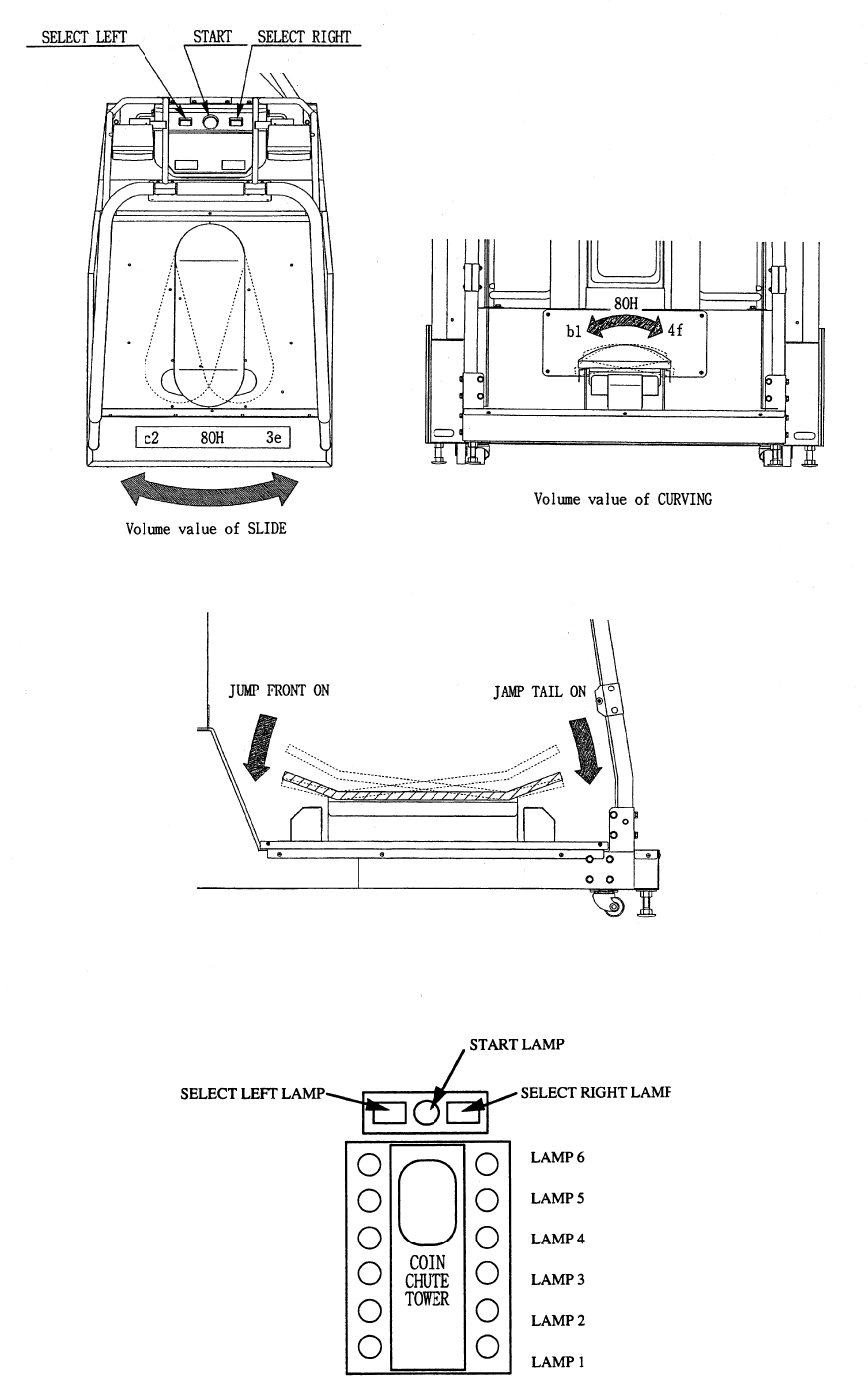
7 - 5 OUTPUT TEST
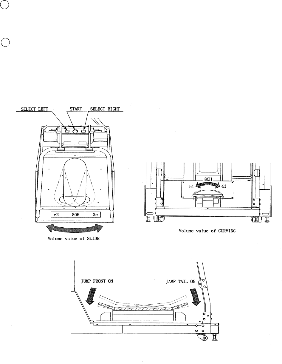
CURVING indicates the value of the volume
which detects the inclination of the Foot Controller’s
horizontality. SLIDE refers to the value of the volume which
detects the right/left swing of the Skate Board (Fig 7.4b)
JUMP FRONT and JUMP TAIL indicate the status of the
Sensor which detects the stepping on the backward/forward
parts of the Skate Board (Fig. 7.4c).
At the time of Centering the Volume (the Skate Board is level and faces the front), the Volume value is set to 180+/-8,
and if the Volume value varies in a natural manner matching the operation of the Skate Board and meeting the operation
in the right/left direction evenly, then the product allows for satisfactory play.
If the Volume value is widely deviated from the 180+/-8 which is set at the time of centering, or the value does not vary
evenly in the right/left operation, the game can not be played satisfactorily, and also this causes Volume damage. Adjust
the Volume by referrring to 7-10, or adjust the gear engagement of the Volume by referring to section 8, or replace the
Volmue.
30
Fig. 7.4b
Fig. 7.4c
Fig. 7.5b
31
C.R.T. TEST 1/2
RED
GREEN
BLUE
WHITE
PRESS TEST BUTTON TO CONTINUE
Select C.R.T. TEST to cause the MONITOR to display the
screen shown left, allowing MONITOR adjustment status
to be checked.
Periodically check the MONITOR adjustment status on
this screen.
The screen (1/2) enables color adjustment check to be
performed. The color bar of each of the 4 colors, i.e.,red,
green, blue, and white, is the darkest at the extreme left and
becomes brighter towards the extreme right.
Press the TEST BUTTON to shift to the next screen (2/2).
The screen (2/2) allows screen size and distortion to be
tested.
Check if the CROSSHATCH FRAME LINE goes out of
the screen and if the crosshatch lines are distorted.
Press the TEST BUTTON to return to the MENU mode.
(FIG. 6.2)
This enables sound used in the game to be checked.
Sound related memory and each speaker are checked.
Press the SERVICE BUTTON to bring the arrow to the
desired sound item to be tested. SE refers to sound
effects and BGM refers to background music.
Each time the SERVICE BUTTON is pressed, the
numeral displayed on the screen counts up and sound is
admitted.
Bring the “>” to EXIT and press the TEST BUTTON to
return to the MENU MODE.
SOUND TEST
SE : ( 0 )
BGM : ( 0 )
>EXIT
SELECT WITH SERVICE BUTTON
PRESS TEST BUTTON TO EXIT
C.R.T. TEST 2/2
PRESS TEST BUTTON TO EXIT
7 - 7 C.R.T. TEST
7 - 6 SOUND TEST
FIG. 7.6 SOUND TEST
FIG. 7.7 C.R.T. TEST
32
7 - 8 GAME ASSIGNMENTS
Selecting the GAME ASSIGNMENTS in the MENU mode causes the present game settings
to be displayed and also the game settings changes (game difficulty, etc.) can be made. Each
item displays the following content.
SETTING CHANGE PROCEDURE
Press the SERVICE BUTTON to move the “>” to the desired item.
Choose the desired setting change item by using the TEST BUTTON.
To return to the MENU mode, move the arrow to EXIT and press the TEST BUTTON.
1
2
ADVERTISE SOUND
Determines wether ADVERTISE SOUND is to be
emitted or not by the setting to ON when emitting
it and to OFF when not emitting it.
GAME ASSIGNMENTS
ADVERTISE SOUND ON
GAME DIFFICULTY 4 / 8
>EXIT
SELECT WITH SERVICE BUTTON
AND PRESS TEST BUTTTON
3
Setting changes cannot be stored unless the TEST BUTTON is pressed
while the arrow is on EXIT.
The Following FIGURES/TABLES show the factory recommended settings.The Following FIGURES/TABLES show the factory recommended settings.
The Following FIGURES/TABLES show the factory recommended settings.The Following FIGURES/TABLES show the factory recommended settings.
The Following FIGURES/TABLES show the factory recommended settings.
GAME DIFFICULTY
Sets the Game Difficulty in 8 catagories from 1 to
8. The greater the number is, the higher the
difficulty level becomes.
33
The “COIN ASSIGNMENTS” mode permits you to set the start number of credits, as well as the basic numbers
of coins and credits. This mode expresses “how many coins correspond to how many credits.”
SETTING CHANGE PROCEDURE
Press the SERVICE BUTTON to move the arrow to the desired item.
Choose the desired setting change item by using the TEST BUTTON.
To return to the MENU mode, move the arrow to EXIT and press the TEST BUTTON.
COIN CHUTE TYPE
Sets the combination of the number of COIN CHUTEs and
the number of players as applicable. In the case that the
COIN CHUTE is changed, be sure the setting is made in a
manner meeting the replaced coin chute.
COMMON:
Coins are accepted in common for both players.
INDIVIDUAL:
Each player uses a coin chute which accepts coins indepen-
dently.
7 - 9 COIN ASSIGNMENTS
CREDIT TO START
Number of credits required for starting game (1~5 credits are selected.)
CREDIT TO CONTINUE
Number of credits required for continuing game (1~5 credits are selected.)
COIN/CREDIT SETTING
Sets the CREDITS increase increment per coin insertion. There are 27 setings from #1 to #27, expressed in
XX CREDIT as against XX COINS inserted. (TABLE 7.9a, 7.9b) #27 refers to FREE PLAY.
When the COIN CHUTE TYPE is set to INDIVIDUAL, there are some setting numbers not displayed as
indicated in TABLE 7.9b.
MANUAL SETTING
This allows credit increase setting as against coin insertion to be further set in the manner finer than COIN/
CREDIT SETTING (refer to TABLE 7.9c).
1
2
3
COIN ASSIGNMENTS
COIN CHUTE TYPE COMMON
CREDIT TO START 2 CREDITS
CREDIT TO CONTINUE 1 CREDIT
COIN/CREDIT SETTING #1
CHUTE#1 1 COIN 1 CREDIT
CHUTE#2 1 COIN 1 CREDIT
MANUAL SETTING
>EXIT
SELECT WITH SERVICE BUTTON
AND PRESS TEST BUTTON
Setting changes cannot be stored unless the TEST BUTTON is pressed
while the arrow is on EXIT.
34
TABLE 7.9a COIN/CREDIT SETTING (COIN CHUTE COMMON TYPE)
SETTING FUNCTIONING OF CHUTE#1
SETTING #1 1 COIN 1 CREDIT
SETTING #2 1 COIN 2 CREDITS
SETTING #3 1 COIN 3 CREDITS
SETTING #4 1 COIN 4 CREDITS
SETTING #5 1 COIN 5 CREDITS
SETTING #6 1 COIN 2 CREDITS
SETTING #7 1 COIN 5 CREDITS
SETTING #8 1 COIN 3 CREDITS
SETTING #9 1 COIN 4 CREDITS
SETTING #10 1 COIN 5 CREDITS
SETTING #11 1 COIN 6 CREDITS
SETTING #12 2 COINS 1 CREDIT
SETTING #13 1 COIN 1 CREDIT
SETTING #14 1 COIN 2 CREDITS
SETTING #15 1 COIN 1 CREDIT
2 COINS 3 CREDITS
SETTING #16 1 COIN 3 CREDITS
SETTING #17 3 COINS 1 CREDIT
SETTING #18 4 COINS 1 CREDIT
SETTING #19 1 COIN 1 CREDIT
2 COINS 2 CREDITS
3 COINS 3 CREDITS
4 COINS 5 CREDITS
SETTING #20 1 COIN 5 CREDITS
SETTING #21 5 COINS 1 CREDIT
SETTING #22 1 COIN 2 CREDITS
SETTING #23 2 COINS 1 CREDIT
4 COINS 2 CREDITS
5 COINS 3 CREDITS
SETTING #24 1 COIN 3 CREDITS
SETTING #25 1 COIN 1 CREDIT
2 COINS 2 CREDITS
3 COINS 3 CREDITS
4 COINS 4 CREDITS
5 COINS 6 CREDITS
SETTING #26 1 COIN 1 CREDITS
SETTING #27 FREE PLAY
35
MANUAL SETTING
Selecting MANUAL SETTING in the COIN ASSIGNMENTS mode displays the following screen.
FIG. 7.9b MANUAL SETTING
BONUS ADDER NO BONUS ADDER
2 COINS GIVE 1 EXTRA COIN
3 COINS GIVE 1 EXTRA COIN
4 COINS GIVE 1 EXTRA COIN
5 COINS GIVE 1 EXTRA COIN
6 COINS GIVE 1 EXTRA COIN
7 COINS GIVE 1 EXTRA COIN
8 COINS GIVE 1 EXTRA COIN
9 COINS GIVE 1 EXTRA COIN
Table 7.9c MANUAL SETTING
Determines Coin/Credit setting.
This sets how many coins should be inserted to obtain one Service Coin.
This sets how many tokens one coin represents.
COIN TO CREDIT 1 COIN 1 CREDIT
2 COINS 1 CREDIT
3 COINS 1 CREDIT
4 COINS 1 CREDIT
5 COINS 1 CREDIT
6 COINS 1 CREDIT
7 COINS 1 CREDIT
8 COINS 1 CREDIT
9 COINS 1 CREDIT
COIN CHUTE MULTIPLIER 1 COIN COUNTS AS 1 COIN
1 COIN COUNTS AS 2 COINS
1 COIN COUNTS AS 3 COINS
1 COIN COUNTS AS 4 COINS
1 COIN COUNTS AS 5 COINS
1 COIN COUNTS AS 6 COINS
1 COIN COUNTS AS 7 COINS
1 COIN COUNTS AS 8 COINS
1 COIN COUNTS AS 9 COINS
MANUAL SETTING
COIN TO CREDIT 1 COIN 1 CREDIT
BONUS ADDER NO BONUS ADDER
COIN CHUTE #1 MULTIPLIER
1 COIN COUNTS AS 1 COIN
COIN 1 2 3 4 5 6 7 8 9
CREDIT 1 2 3 4 5 6 7 8 9
COIN CHUTE #2 MULTIPLIER
1 COIN COUNTS AS 1 COIN
COIN 1 2 3 4 5 6 7 8 9
CREDIT 1 2 3 4 5 6 7 8 9
>EXIT
SELECT WITH SERVICE BUTTON
AND PRESS TEST BUTTON
1
2
3
3
1
2

36
7 - 10 BOARD SETTING
In the Board setting, the value for each of CURVING AND SLIDE Volumes (which detects the operation of the
Skate Board) can be set.
STANDARD
Setting the value set at the time of centering automatically
determines the input range.
MANUAL
Manually sets both of the value set at the time of centering
and the input range (maximum and minimum).
DATA
Indicates the Skate Board’s present Volume value. When the
Skate Board is operated, the value varies.
CENTER
Present Volume value set at this time of centering the Skate
Board.
MINIMUM
The Volume’s Mimimum value set at present.
MAXIMUM
The Volume’s Maximum value set at present.
If the Skate Board can not be operated satisfactorily even
after the Volume setting is performed in this mode, adjust or
replace the Volume by refering to Section 8.
In the MENU MODE, selecting the BOARD SETTING
displays the screen shown left. This mode allows for setting
the centering position value and in-out range of the Volume
which detects the operation of the Skate Board. The Skate
Board Volume value differs depending on the specific
machine and also, can be deviated during transportation.
After installation and assembling, check the Volume value
and its variations in this mode. If the Value is widley varies
from the recommended value, set the Volume value in the
following procedure:
These are two setting methods, i.e., STANDARD and
MANUAL.
Enter the BOARD SETTING mode.
Select STANDARD and press the TEST BUTTON. The
screen changes to Fig. 7.10b.
Set the Skate Board in the center/flat position. The Value
obtained at this time is the CENTER value.
Press the TEST BUTTON to exit from BOARD SETTING,
display the BOARD SETTING DATA HAS BEEN DIS-
PLAYED message, and change the setting. The screen
returns to the menu mode.
GUN SETTING
STANDARD
MANUAL
>EXIT
CURVING SLIDE
DATA 80 80
CENTER 80 80
MINIMUM 4f 3e
MAXIMUM b1 c2
SELECT WITH SERVICE BUTTON
AND PRESS TEST BUTTON
Fig. 7.10a BOARD SETTING
Fig. 7.10b STANDARD SETTING
BOARD SETTING
BEFORE EXITING [ BOARD SETTING ] ,
SET THE BOARD IN THE CENTER/FLAT POSITION .
MESSAGE
CURVING SLIDE
DATA 80 80
CENTER 80 - 80 80 - 80
MINIMUM 4f - 4f 3e - 3e
MAXIMUM b1 - b1 c2 - c2
PRESS TEST BUTTON TO EXIT

37
BOARD SETTING
SWING/BANK THE BOARD
AS FAR/DEEP AS POSSIBLE.
BEFORE EXITING [ BOARD SETTING ] ,
SET THE BOARD IN THE CENTER/FLAT POSITION.
MESSAGE
CURVING SLIDE
DATA 80 80
CENTER 80 - 80 80 - 80
MINIMUM 4f - 4f 3e - 3e
MAXIMUM b1 - b1 c2 - c2
PRESS TEST BUTTON TO EXITt
Enter the BOARD SETTING mode.
Select MANUAL and press the TEST BUTTON. the screen changes to 7.10c.
Get on the Skate Board, operate for right/left CURVING and inclination SLIDE evenly in both directions to
set the minimum/maximum Volume values. At this time, setting a wider input range makes turning more
difficult in actual play and setting a narrower input makes turning easier.
Set the Skate Board in the center direction and level position. What is set at this time is the CENTER value.
Press the TEST BUTTON to exit from BOARD SETTING to display BOARD SETTING DATA HAS BEEN
UPDATED message and change the setting. The screen returns to the MENU MODE.
If the Board is not operated and settings are not changed, the message of “THE BOARD SETTINGS HAS
NOT BEEN CHANGED. BACKUP DATA HAS NOT BEEN UPDAED” is displayed.
When exiting from the BOARD SETTING screen without setting the Skate Board to the center position, the
machine will determine the inclination and angle of the Skate Board at that time as the center position and
therefore, the game can not be played satisfactorily.
When the Skate Board is set to the center postion, if the Volume value is not within the range of 80H-/+8,
then the Volume gear engagement fault an Volume malfunctioning may be considered. By referring to
section 8, take appropriate countermeasures.
MANUAL SETTING
Fig. 7.10c MANUAL SETTING

38
On page (2/2), each play frequency is displayed. When
setting difficulty levels, the frequency can be refered to as a
standard.
When in the PAGE 2/2 mode, press the TEST BUTTON to
return to the MENU mode (FIG.7.2).
7 - 11 BOOKKEEPING
Choosing BOOKKEEPING in the MENU mode displays the data of operating status up to the present are shown on 2
pages. Press the TEST BUTTON to proceed to PAGE 2/2.
BOOKKEEPING PAGE1/2
COIN REPORT
COIN CHUTE #1 XXXXXXXXXXX
COIN CHUTE #2 XXXXXXXXXXX
TOTAL COINS XXXXXXXXXXX
COIN CREDITS XXXXXXXXXXX
SERVICE CREDITS XXXXXXXXXXX
TOTAL CREDITS XXXXXXXXXXX
NUMBER OF GAMES
1 P GAMES XXXXXXXXXXX
2 P GAMES XXXXXXXXXXX
NUMBER OF CONTINUE
1 P GAMES XXXXXXXXXXX
2 P GAMES XXXXXXXXXXX
TOTAL TIME XDXXHXXMXXS
PLAY TIME XDXXHXXMXXS
AVERAGE PLAY TIME XXMXXS
LONGEST PLAY TIME XXMXXS
SHORTETEST PLAY TIME XXMXXS
PRESS TEST BUTTON TO CONTINUE
FIG. 7.11a BOOKKEEPING (1/2)
COIN CHUTE#*:
Number of coins put in each Coin Chute.
TOTAL COINS:
Total number of activations of Coin Chutes.
COIN CREDITS:
Number of credits registered by inserting coins.
SERVICE CREDITS:
Credits registered by the SERVICE BUTTON.
TOTAL CREDITS:
Total number of credits (COIN CREDITS+SERVICE
CREDITS).
TOTAL TIME:
The total energized time.
BOOKKEEPING PAGE 2/2
TIME HISTOGRAM
0M00S ~ 0M29S XXXXXXXX
0M30S ~ 0M39S XXXXXXXX
0M40S ~ 0M49S XXXXXXXX
0M50S ~ 0M59S XXXXXXXX
1M00S ~ 1M09S XXXXXXXX
1M10S ~ 1M19S XXXXXXXX
1M20S ~ 1M29S XXXXXXXX
1M30S ~ 1M39S XXXXXXXX
1M40S ~ 1M49S XXXXXXXX
1M50S ~ 1M59S XXXXXXXX
4M00S ~ 4M09S XXXXXXXX
4M10S ~ 4M19S XXXXXXXX
4M20S ~ 4M29S XXXXXXXX
4M30S ~ 4M39S XXXXXXXX
4M40S ~ 4M49S XXXXXXXX
4M50S ~ 4M59S XXXXXXXX
5M00S ~ XXXXXXXX
PRESS TEST BUTTON TO EXIT
FIG. 7.11b BOOKKEEPING (2/2)

39
Clears the contents of BOOKKEEPING and high
score player ranking entry.
When clearing, bring the arrow to “YES” and
when not clearing, to “NO”, by using the SER-
VICE BUTTON, and push the TEST BUTTON.
When the data has been cleared, “COMPLETED”
will be displayed. Bring the arrow to “NO” and
press the TEST BUTTON to cause the MENU
mode to return on to the screen.
Note that the contents of the GAME SETTING,
COIN SETTING, and BOARD SETTING are not
affected by BACKUP DATA CLEAR operation.
BACKUP DATA CLEAR
YES (CLEAR)
>NO (CANCEL)
MESSAGE
SELECT WITH SERVICE BUTTON
PRESS TEST BUTTON TO EXIT
7 - 12 BACKUP DATA CLEAR
FIG. 7.12 BACKUP DATA CLEAR
40
8 . MAINTENANCE OF MECHANISM UNIT
In order to prevent an electric shock and short circuit, be sure to turn power off
before performing work by touching the interior parts of the product.
Be careful so as not to damage wirings. Damaged wiring can cause an electric shock
or short circuit accident.
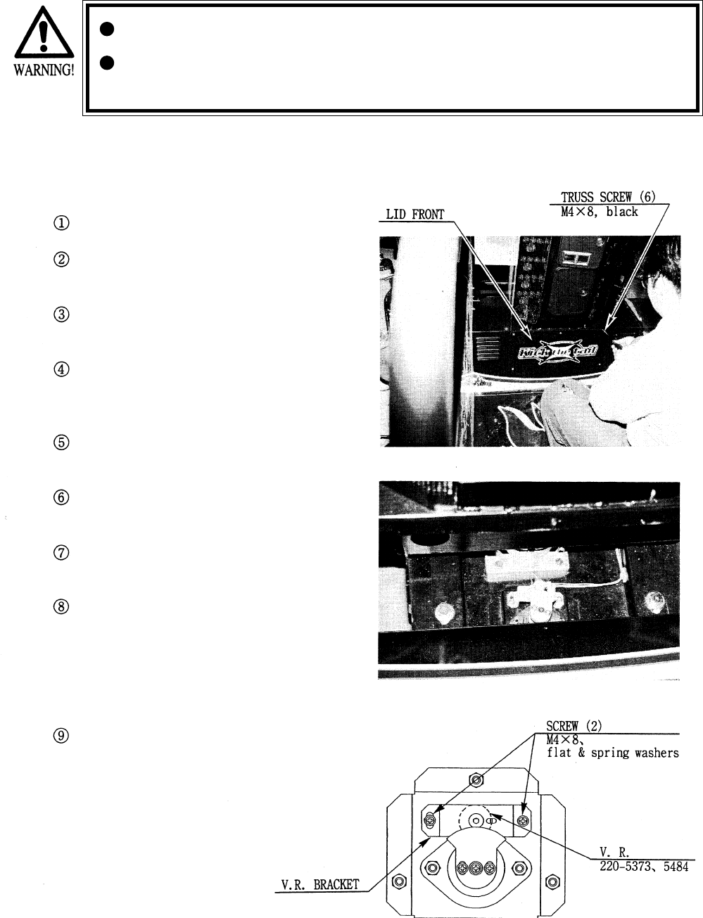
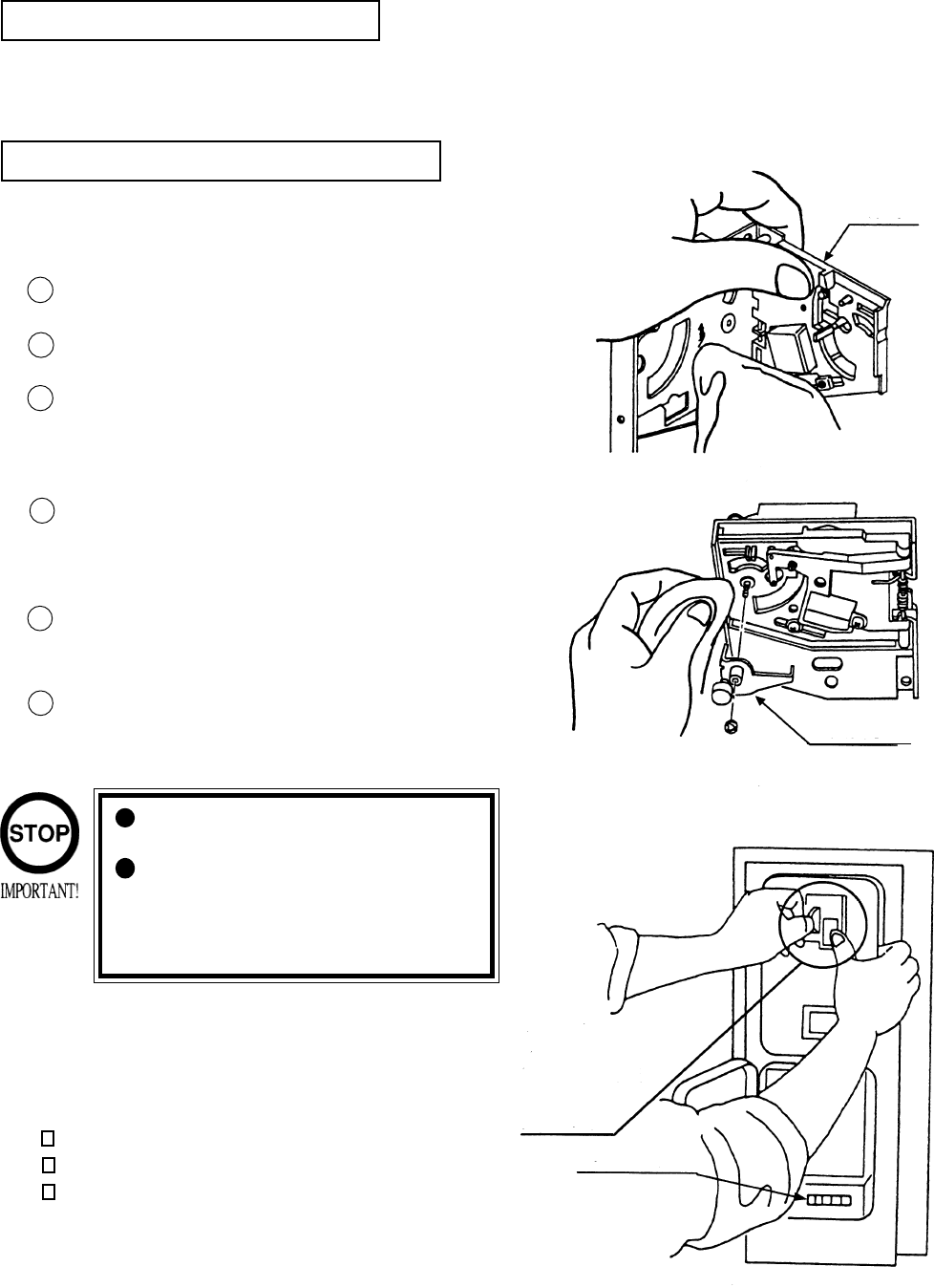
8 - 1 ADJUSTMENT AND REPLACEMENT OF SLIDE VOLUME
Turn the power OFF.
Take out the 6 screws and remove LID FRONT
(photo 8.1a)
The mechanism part of the SLIDE Volume can be
viewed (photo 8.1b)
Loosen the 2 screws which secure the Volume
bracket to move the Volume Bracket
Move the Volume Bracket to adjust gear engage-
ment.
Fasten the 2 screws to secure the Volume Bracket.
Perform Volume setting as per the Board setting
procedure (7-10) in the TEST MODE.
If the Volume is malfuntioning, first disconnect the
connector which is connected to the Volume,
remove the 2 screws which secure the Volume
Bracket, and remove the Volume Bracket together
with the Volume as is attached
Remove the gear from the Volume Shaft and replace
the Volume.
Photo 8.1a
Photo 8.1b
Fig. 8.1
41
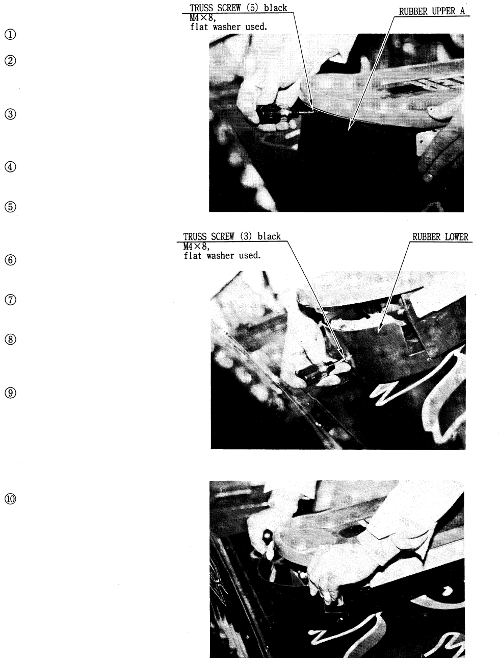
8 - 2 ADJUSTMENT AND REPLACEMENT OF CURVING VOLUME
Turn the power SW OFF.
Take out the 5 Truss screws
and remove Rubber Upper
A (photo 8.2a).
Take out the 3 Truss screws and remove
Rubber Lower (photos 8.2b & 8.2c).
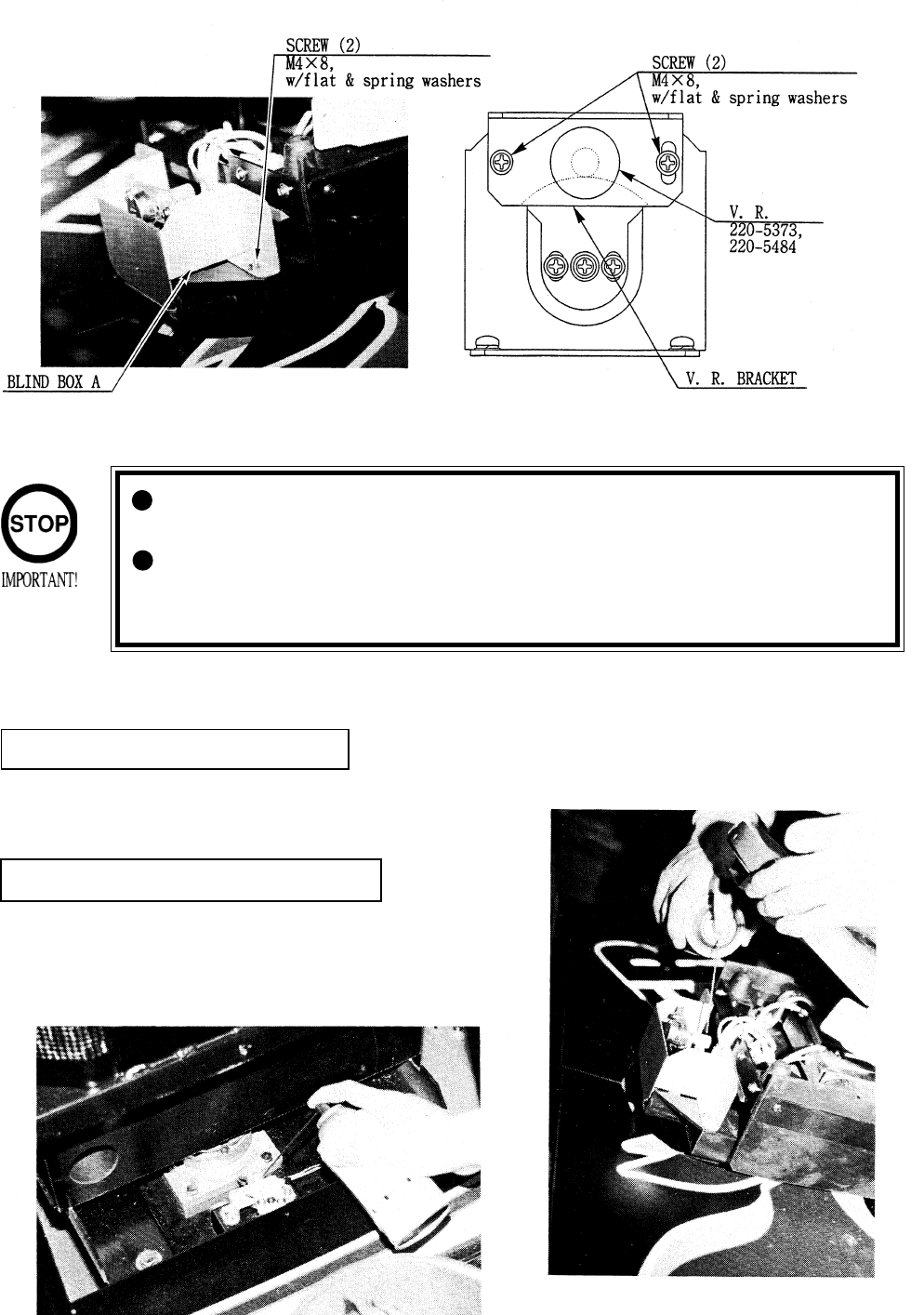
Take out the 2 screws and remove blind
box A (photo 8.2d).
Loosen the 2 screws, which secure the
Volume Bracket, to move the Volume
Bracket (Fig. 8.2).
Move the Volume Bracket to adjust
gear engagement.
Fasten the 2 screws to secure
the Volume Bracket.
When the Volume is
malfuntioning, first disconnect
the connector which is con-
nected to the Volume, take out
the 2 screws which secure the
Volume Bracket, together with
the Volume as is attached.
Perform Volume setting as per BOARD
SETTING (7-10) in the TEST MODE.
Disengage the gear from the Volume
shaft and replace the Volume.
Photo 8.2a
Photo 8.2b
Photo 8.2c
42
Besure to use designated grease. Using undesignated grease can cause parts
damage.
Do not apply greasing to places other than those specified. Greasing to
undesignated places can cause malfunctioning and the qualitative deterioration
of parts.
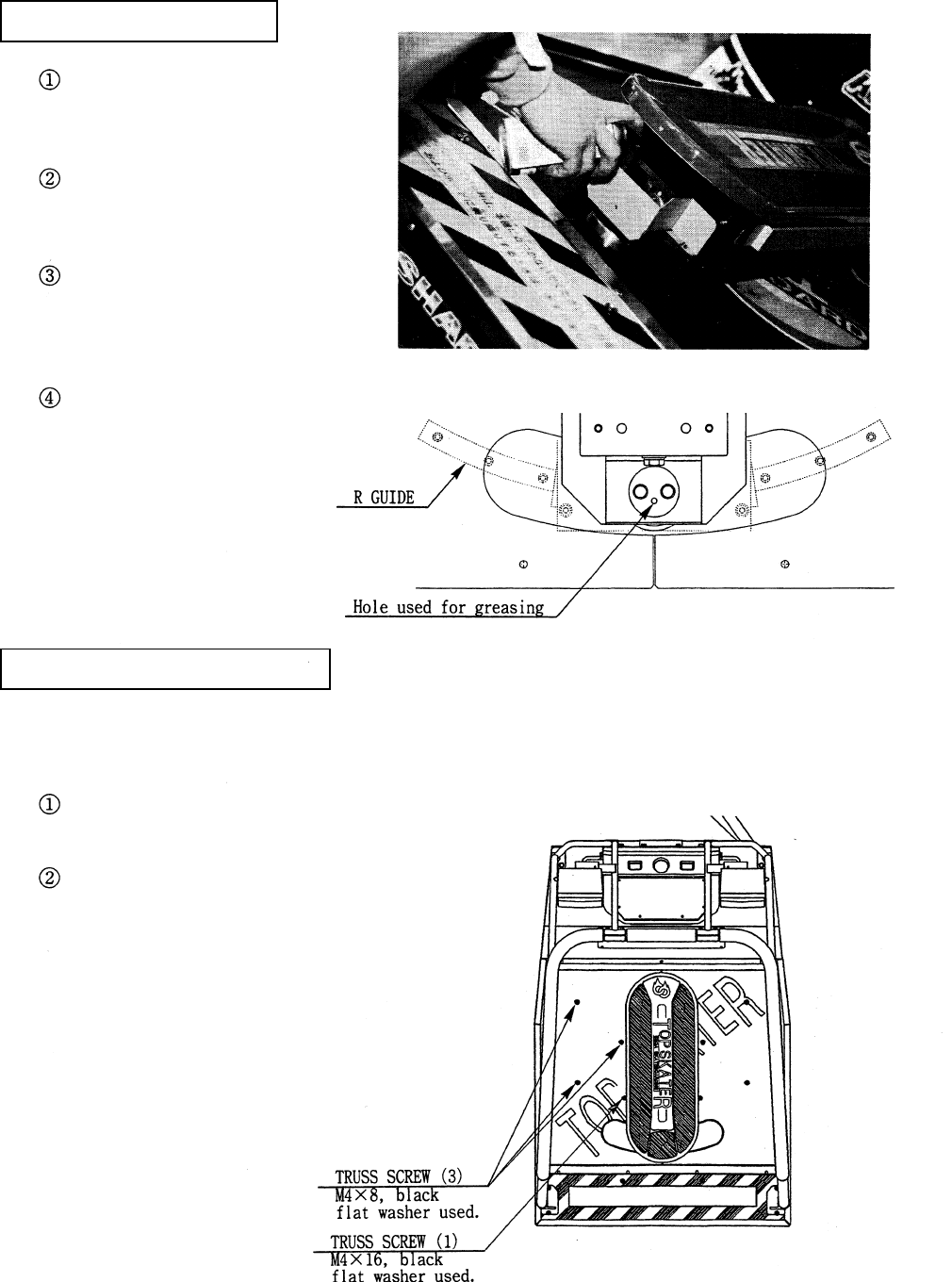
Once every 3 months, apply greasing to the Volume gear mesh portion and the R guide. For spray
greasing, use GREASE MATE (PART No. 090-0066).
GREASING TO SLIDE VOLUME
GREASING TO CURVING VOLUME
Remove LID FRONT to apply greasing to the
Volume gear portion (photo 8.3a).
Remove Rubber Upper A and Rubber Lower to
apply greasing to the Volume gear portion
(photo 8.3b).
8 - 3 GREASING
Fig. 8.2
Photo 8.2d
Photo 8.3a
Photo 8.3b
43
GREASING TO BRAKE GEAR
GREASING TO R GUIDE
Remove Rubber Upper A and Rubber
Lower from the rear part of the Skate
Board.
The hole (through which greasing is
applied) is located inside Blind Box A.
Insert the spray grease nozzle into the
hole used for greasing, and perform spray
greasing (photo 8.3c and Fig 8.3a).
Move the Skate Board right&left and
ensure that the R Guide is lubricated
smoothly and satisfactorily all over.
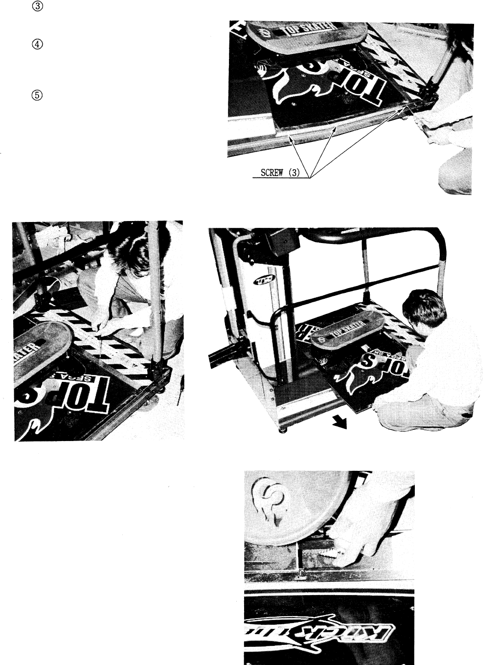
Take out the 4 screws which secure the Rear Lid
(Fig. 8.3b).
Take out the 3 screws to remove the Sash Part on the
side to be removed (photo 8.3d).
Move either right or left REAR LID of the Rear Cabinet to apply greasing to the Brake Gear.
Fig. 8.3a
Fig. 8.3b
Photo 8.3c
44
Loosen the screw which secures the Rear
Lid (photo 8.3e).
Move the Rear Lid so as to have the
square hole used for greasing appear
(photo 8.3f).
It the spray grease nozzle into the square
hole, and apply greasing to the Brake
Gear engagement portion (photo 8.3g).
Photo 8.3d
Photo 8.3e Photo 8.3f
Photo 8.3g
45
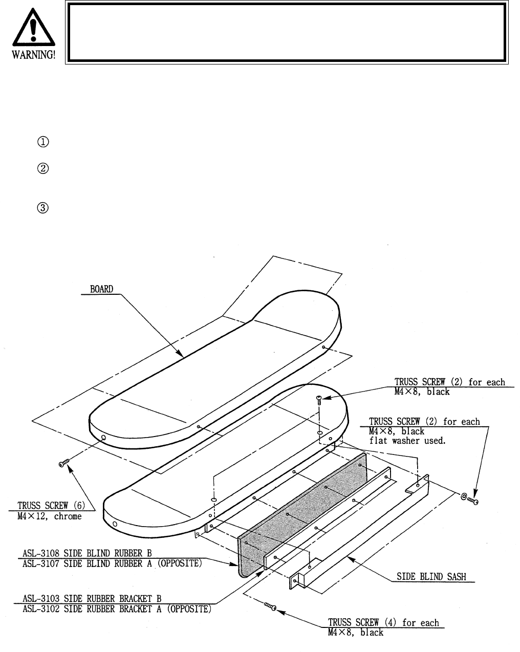
For the replacement of Rubber Upper A and Rubber Lower, refer to 8 - 2.
Take out the 4 screws to remove Side Blind Sash Fasten the 2 screws on the side portion together with
Rubber Upper A.
Take out the 4 screws, remove Side Rubber and Side Rubber Bracket to replace the Side Rubber.
Take out the 6 screws to remove the Skate Board.
If the hazard preventive parts have any irregularity, be sure to replace the part(s)
immediatly. Operating with the part(s) damaged or omitted can cause injury.
8 - 4 REPLACEMENT OF HAZARD PREVENTIVE PARTS
Fig. 8.4
46
The coin selector should be cleaned
once every 3 months. When cleaning,
follow the procedure below:
Turn the power for the machine OFF.
Open the coin chute door.
Open the gate and dust off by using a
soft brush (made of wool, etc.).
Remove and cleen smears by using a
soft cloth dipped in water or diluted
chemical detergent and then squeezed
dry.
Remove the CRADLE.
When removing the retaining ring(E-
ring), be very careful so as not to bend
the shaft.
Remove stain from the shaft and pillow
portions by wiping off with a soft cloth,
etc.
After wiping as per #5 above, further
apply a dry cloth, etc. to cause the coin
selector to dry completely.
Once a month, when performing the COIN SW
TEST, simultaneously check the following:
Does the Coin Meter count satisfactorily?
Does the coin drop into the Cashbox correctly?
Is the coin rejected when inserted while keeping
the REJECT BUTTON is pressed down?
If the coin is not rejected when the REJECT BUTTON is pressed, open the coin chute door
and open the selector gate. After removing the jamed coin, put a normal coin in and check to
see that the selector correctly functions.
1
2
3
4
5
6
COIN INSERTION TEST
HANDLING THE COIN JAM
CLEANING THE COIN SELECTOR
9 . COIN SELECTOR
Never apply machine oil, etc. to
the coin selector
After cleaning the Coin Selecting,
Insert a regular coin in the normal
working status and ensure that
the Selector correctly functions.
GATE
FIG. 9a
FIG.9b
COIN METER
FIG. 9c
CRADLE
Insert a coin
while keeping
the Reject
Button pressed
down and check
if it is
rejected.
47
OPTIONAL DOLLAR BILL ACCEPTOR
THE COIN DOOR ASSEMBLY USED ON TOP SKATE TOP SKATE
TOP SKATE TOP SKATE
TOP SKATE COMES EQUIPPED
TO ACCEPT A DOLLAR BILL ACCEPTOR. ALL NEEDED WIRING CON-
NECTIONS ARE CONVIENENTLY LOCATED INSIDE THE GAME FOR
THIS APPLICATION.
THE COIN DOOR CAN ACCCOMMODATE THE FOLLOWING
VALIDATORS:
HOLE POSITION#1 VFM5 (MARS)
(FORWARD-MOST POSITION) AL4 (MARS)
HOLE POSITION#2 VFM2 (MARS)
VFM4 (MARS)
DBV45 (JCM)
HOLE POSITION #3 CURRENTLY NOT USED
HOLE POSITION #4 DSI01*
*The back flange on the chute can be removed for hold position #4.
If the flange is not removed, it may interfere with the back of the
cabinent.
48
10 . PROJECTOR
10 - 1 CLEANING THE SCREEN
Since the Projector has been adjusted at the time of shipment,
avoid making further adjustments without good reason.
The Projector is subject to color deviation due to Convergence devia-
tion caused by the geomagnetism at the time of installation location
and peripheral magnetic field. After the installation of machine, and
before commencing operation, check for Convergence deviation and if
deviated, make adjustments..
Since the Projector screen is susceptible to damage, pay careful
attention to it’s handling. When cleaning, refrain from using water or
volatile chemical.
Fine adjustments are stored in the Projector. Pressing the Fine Adjustment SW (Convergence
Adjustment) results in entering the Fine Adjustment mode, and this may cause the stored fine
adjustment to be changed. During work other than for adjustment, Should you topuch the Fine
Adjustment SW by mistake, immediately turn power off by using the main SW and then turn it back
on again. If any distortion or color deviation is found in the test mode and adjustments are needed,
use the specified adjustment knob, or perform adjustment by remote control. To find the adjustment
knob, move Cabinet DX and remove the PTV Front Service Door by using the procedure opposite
the one for installing and assembling. In some cases a cover is installed to the Adjustment Knobs.
Remove the Cover.
When the screen surface becomes
dirty with dust, etc., clean it by using
a soft cloth such as gauze. When
water, and volatile chemicals such as
benzine, thinner, etc., spill on the
screen surface, it may be subject to
damage, therefore, do not use them.
Also, since the surfaces are suscep-
tible to damage, refrain from rubbing
them with a hard material or using a
duster.
Fig. 10.1
49
STATIC CONVERGENCE ADJUSTMENT
POWER BUTTON
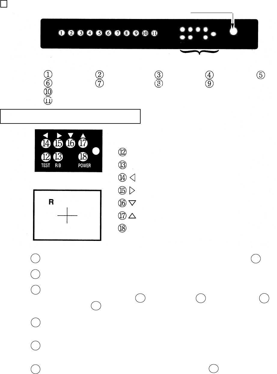
10 - 2 MITSUBISHI PROJECTOR
MITSUBISHI PROJECTOR CONTROL PANEL
TEST Test mode on/off key
R/B key
Left shift key
Right shift key
Lower shift key
Upper shift key
Power button
R/B
POWER
V.POS
CONT
R.H.L.
B.H.L.
H.POS
BRI
R-GAIN
V.W
G-GAIN B-GAIN
H.W
}
Convergence Adjustment SW
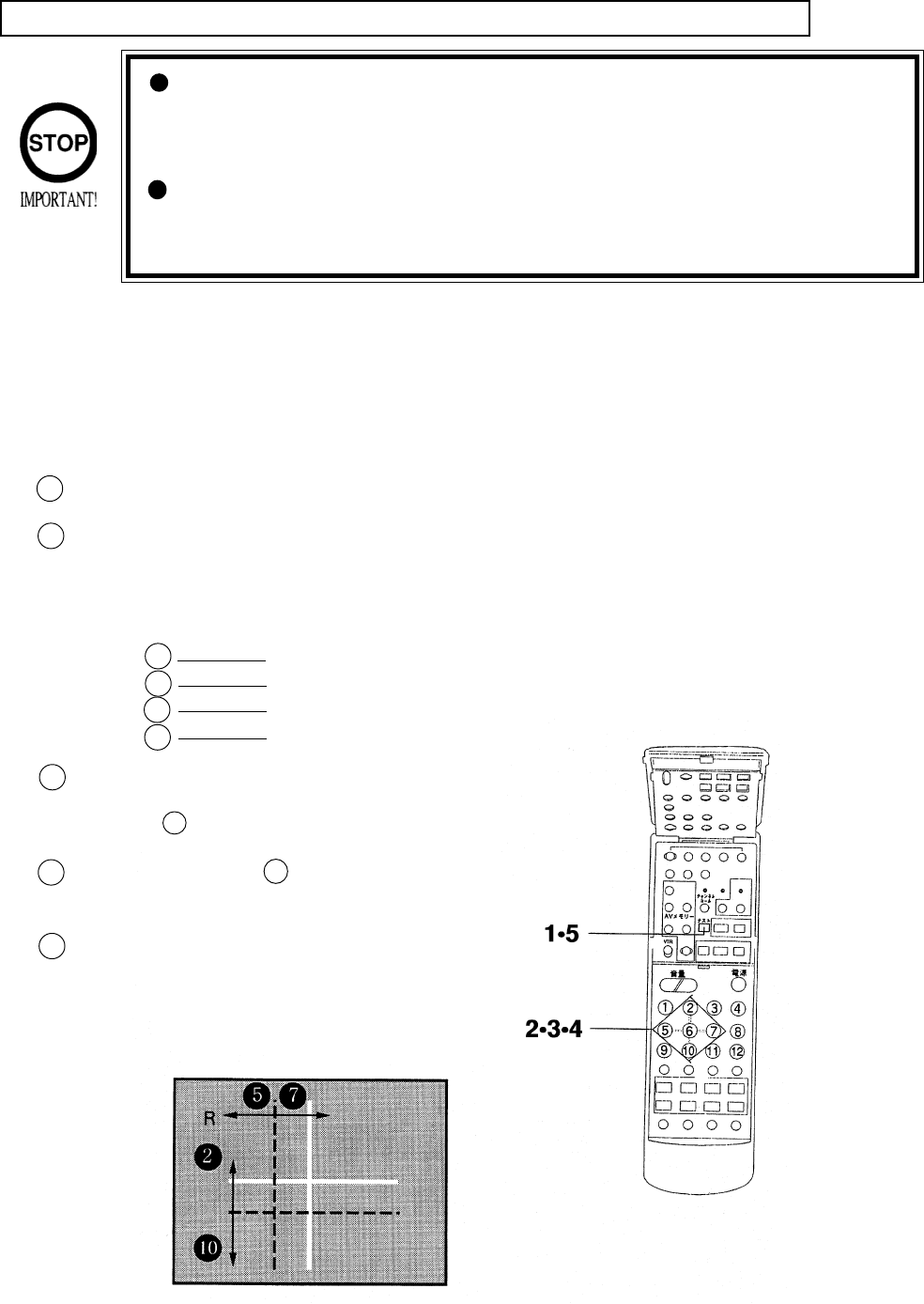
For the Convergence adjustment mode, press the test mode on/off key. 12
Ensure that “R” is displayed on the screen.
Make adjustments so as to cause the red cross pattern to match with the green cross
pattern by using Left shift key 14 , Right shift key 15 , Lower shift key 16 , and
Upper shift key 17 .
By using R/B shift key 13 , cause the red adjustment “R” to shift to blue adjustment
“B” and make sure that “B” is displayed on the screen.
In the same manner as in 3 above, cause the blue cross pattern to match with the
green cross pattern.
After making adjustment, press the test mode on/off key 12 to cancel the conver-
gence adjustment mode.
1
2
3
4
5
6
Linearity adjustments in horizontal directions
(red or blue) are made.
Convergence Adjustment SW
50
Although Remote Control Buttons other than those specified
below do not function even if pressed during Convergence Adjust-
ment, do not press them during adjustment work so as to avoid
causing malfunctioning.
Operate the Remote Control towars the PTV screen. If directed
other than to the PTV screen, the Remote Control does not func-
tion.
BEFORE USING REMOTE CONTROL:
First make sure that the main SW on the Projector’s control panel is ON (the LED adjascent
to the main SW is lit).
The Remote Control has 2 different types. Depending on the type, the Adjustment procedure
is different.
STATIC CONVERGENCE ADJUSTMENT METHOD WITH REMOTE CONTROL
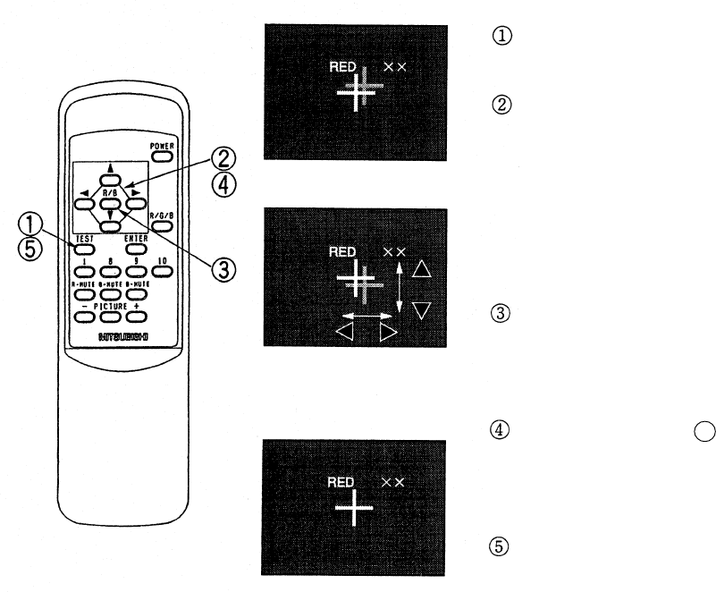
In case of REMOTE CONTROL (Part No. 200-5298):
2
For the Convergence Adjustment mode, press the test button. Ensure that “R” is displayed on the screen.
Make adjustment so as to cause the red cross pattern to match with the green cross pattern.
When the red cross matches the green cross, the green cross turns yellow or white.
Use remote control buttons shown below to move the red cross as follows:
Button to the left
to the right
Upward
Downward
Use Remote Control button 6 to shift “R” to “B”.
Make sure that “B” is displayed on the screen. Each
time Button 6 is pressed, red and blue adjustments
are shifted.
In the same manner as in 2 above, cause the blue
cross to match the green cross. When the blue cross
matches the green cross, the green cross turns white.
After adjustment is made, press the test button to
cancel the Convergence Adjustment mode.
*When 2 minutes or more elapses in the Conver-
gence mode screen without taking any action, the
on-screen adjustment mode will disappear.
5
4
1
3
2
7
5
10
51
Press the TEST KEY to have the red line
adjustment screen appear.
Superimpose the red cross on the green cross at
the center of the screen.
Move the red cross to the left, right, up, and
down respectively with the corresponding
buttons of the remote control.
When the red cross is superimposed on the
green cross, the green cross turns into yellow or
white.
Press the R/B Key to have the blue line adjust-
ment screen appear. Each time R/B Key is
pressed, the red line and blue line will be
alternated.
In the manner similar to 2 above, press each
key to superimpose the blue cross on the green
cross. When it is superimposed, the cross in the
center will become white.
Press the TEST KEY to exit from the adjust-
ment mode.
During STATIC CONVERGENCE Adjustment
Mode, if no action is taken within 5 minutes, the
adjustment mode will be exited automatically.
Red line adjustment
Completion of Adjustment
In case of REMOTE CONTROL (Part No. 200-5532):
52
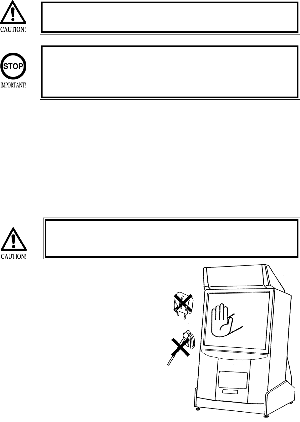
11 . REPLACEMENT OF FLUORESCENT LAMP AND LAMPS
When performing the work, be sure to turn power off. Working
with power on can cause an electric shock or short circuit acci-
dent.
The Flourescent Lamp, when it gets hot, can cause burns. Be
very careful when replacing the Fluorescent Lamp.
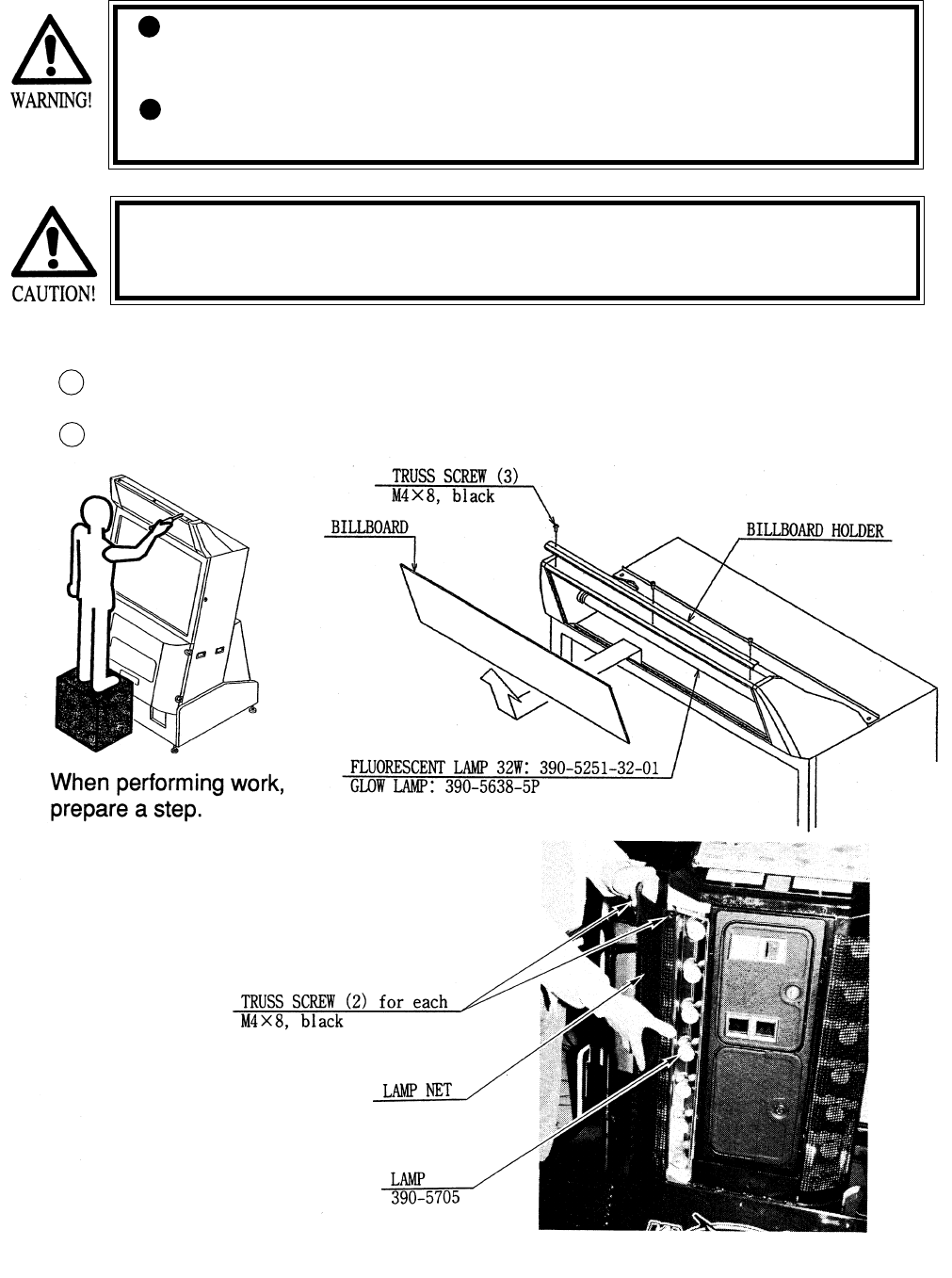
To perform work safely and securely, be sure to prepare a step which is in a
secure and stable condition. Not using a step or using an unstable step can
cause a violent falling down accidents.
11 -1 REPLACEMENT OF FLUORESCENT LAMP
Take off the 3 screws which secure the Holder on the upper part of Billboard.
Take out the billboard from the cabinet and replace the fluorescent lamp (20W)
1
2
Fig. 11.1
Photo 11.2
11 -2 REPLACEMENT OF LAMP
As shown in photo 11.2, take out 2
screws from each “lamp net” to
replace the lamp.
53
ITEMS DESCRIPTION PERIOD REERENCE
CABINET Ensure that adj. are in contact Daily 1
with floor
Check hazard preventive Daily 1
parts
SKATE BOARD Check volume and sensor Monthly 7
Apply greasing to volume Trimonthly 7
gear, R guide and brake gear
COIN SELECTOR Check COIN SW Monthly 7
COIN SELECTOR cleaning Trimonthly 9
PROJECTOR Screen cleaning Weekly 10
Check adjustments Monthly 4, 7, 10
GAME BD Setting check, Monthly 7
INTERIOR Cleaning Annually see above.
POWER PLUG Inspection and cleaning
CABINET SURFACE Cleaning As necessary see below
The items listed below require periodic check and maintenance to retain the performance of
this machine and ensure safe operation.
12 . PERIODIC INSPECTION TABLE
Be sure to check once a year to see if Power Cords are damaged,
the plug is securley inserted, dust is accumulated between the
Socket Outlet and the Power Plug, etc. Using the product with
dust as is accumulated can cause a fire or electrical shock.
Periodically once a year, request the place of contact herin stated
or the Distributer, etc. where the product was purchased from, as
regards the interior cleaning. Using the product with dust as is
accumulated in the interior without cleaning can cause a fire or
accident. Note that cleaning the interior parts can be performed
on a pay-basis.
CLEANING CABINET SURFACES
When the cabinet surfaces are badly soiled, remove stains with a soft cloth dipped in water or
diluted (with water) chemical detergent and squeezed dry. To avoid damaging surface finish,
do not use such solvents as thinner, benzine, etc. other than ethyl alcohol, or abrasives,
bleaching agent and chemical dustcloth.
54
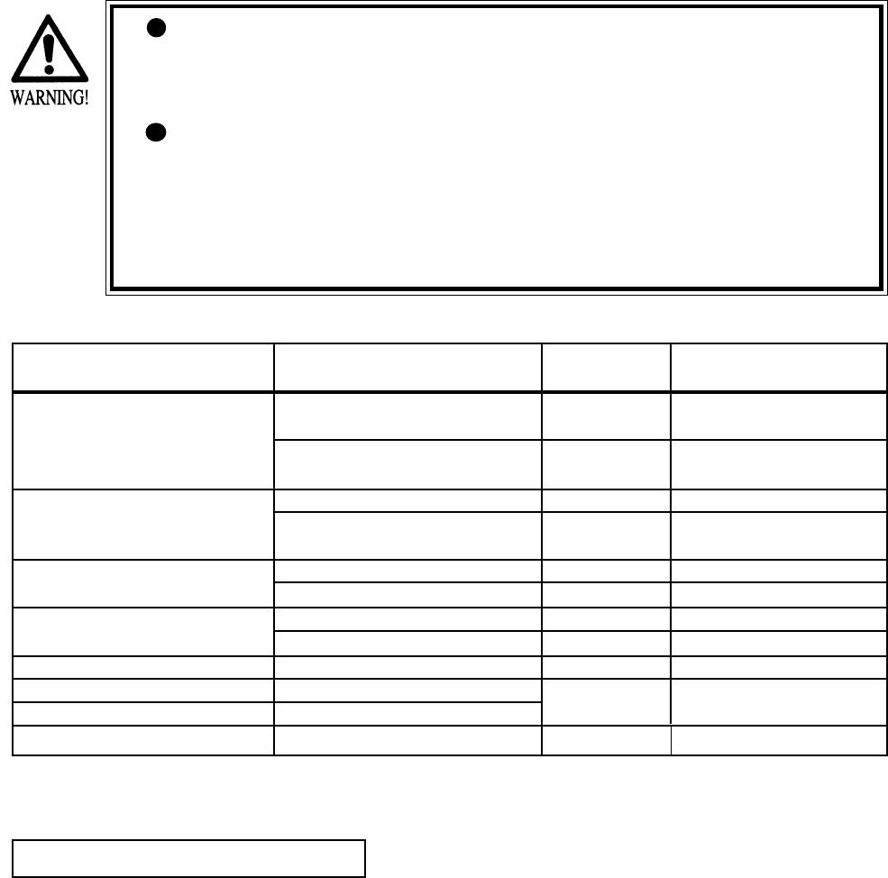
13 . TROUBLESHOOTING
PROBLEMS CAUSE COUNTERMEASURES
With Main SW Power is not supplied. Plug in correctly
ON, no activation Power supply/voltage is not correct. Make sure that power supply/voltage is
correct.
AC main fuse causes the Check fuse. Remove the cause of
power to be cut off due to momentary overload and replace fuse
overload.
Should trouble occur, first check connector connections.
In order to prevent an electric shock, be sure to turn power off before performing
work by touching the interior parts of the product.
Be careful so as not to damage wirings. Damaged wiring can cause an electric shock
or shor circiut accident.
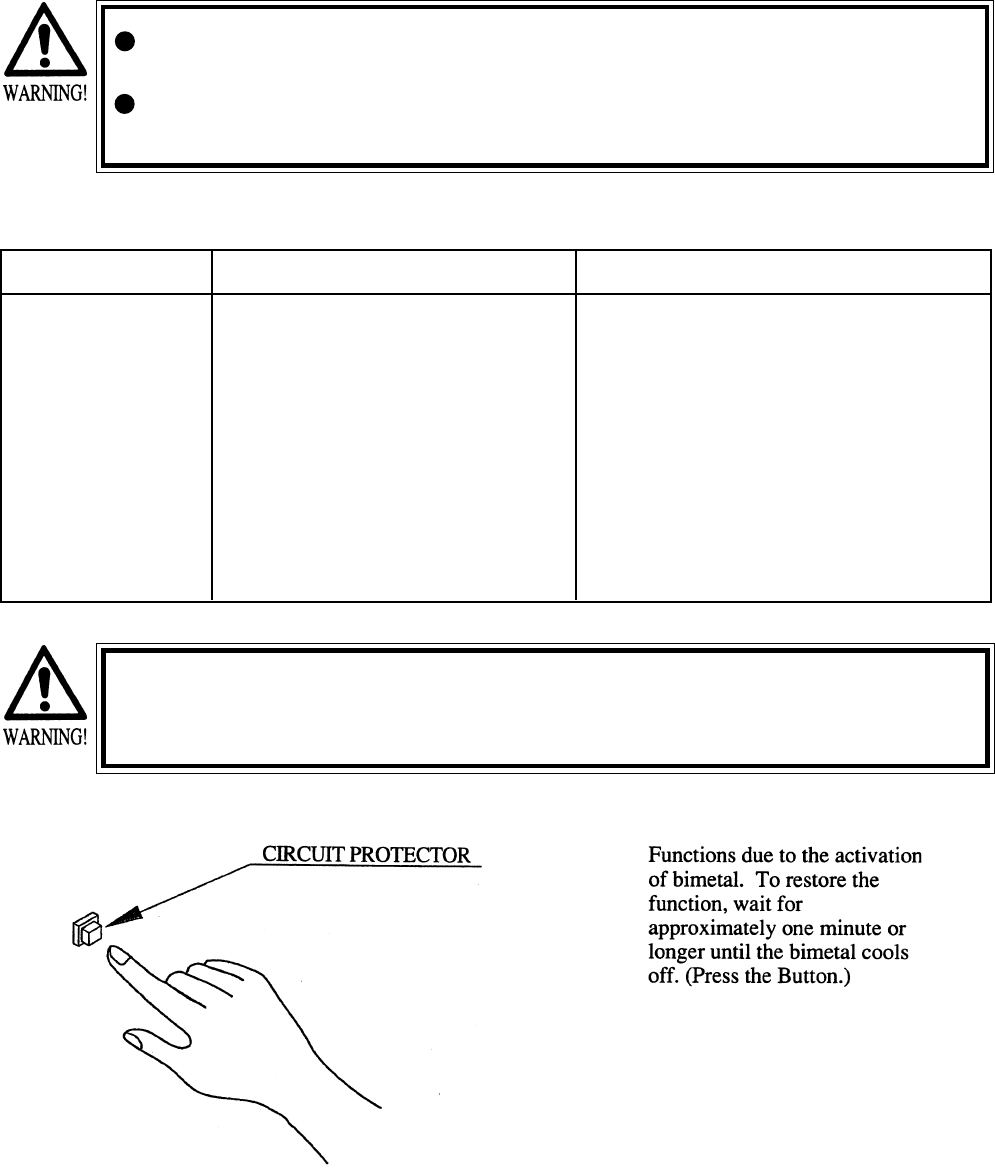
After removing the cause of the functioning of the Circuit protector, reinstate the
Circuit Protector. Depending on the cause of the functioning, using the Circuit Pro-
tector as is without removing the cause could result in generation of heat and fire.
The Circuit Protector functioned due Remove the cause of overload and reset Circuit
to momentary overcurrent. Protector
55
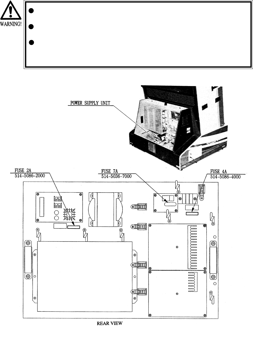
In order to prevent an electric shock, be sure to turn power off before performing
work by touching the interior parts of the product.
Be careful so as not to damage wirings. Damaged wiring can cause an electric shock
or shor circiut accident
After eliminating the cause of the blowing of fuse, replace the fuse.
Depending on the cause of the fuse blowing, using the fuse as is blown can cause
generation of heat resulting in fire.
Photo 13
Fig. 13 POWER SUPPLY UNIT
13 - 1 REPLACEMENT OF FUSE
56
14 . GAME BOARD
In order to prevent an electrical shock, be sure to turn power off before
performing work by touching the interior parts of the product.
Be careful so as not to damage wirings. Damaged wiring can cause an
electric shock or short circuit accident.
Do not expose the Game BD, etc. without a good reason. In this product,
setting changes are made during the test mode. The Game BD need not be
operated. Use the Game BD, etc. as is with the same setting made at the
time of shipment.
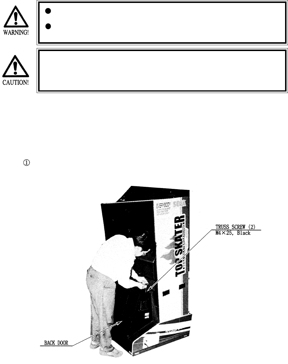
14 -1 REMOVING THE IC BOARD
Remove the Back Door from the rear part of the PTV Base to have the Power Supply Unit
appear. There are three types of fuses on the Power Supply Unit.
Take out the 2 Truss screws, unlock with the Master Key, and remove the Back Door from
the rear part of the Front Cabinet. (photo 14.1a)
Fig. 14.1a
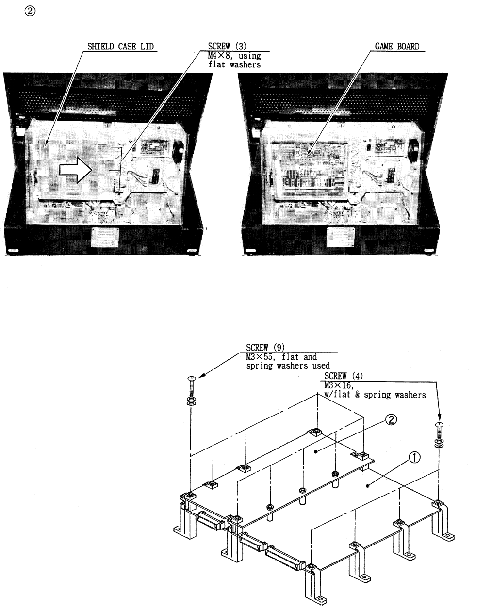
57
GAME BD ASL
(833-13080)
(833-13080-01 : USA)
14 - 2 COMPOSITION OF GAME BOARD
Take out the 3 screws and remove Sheild Case Lid to have the Game Board appear.
(photo 14.1b,c)
Photo 141b Photo 14.1c
Fig.14.2
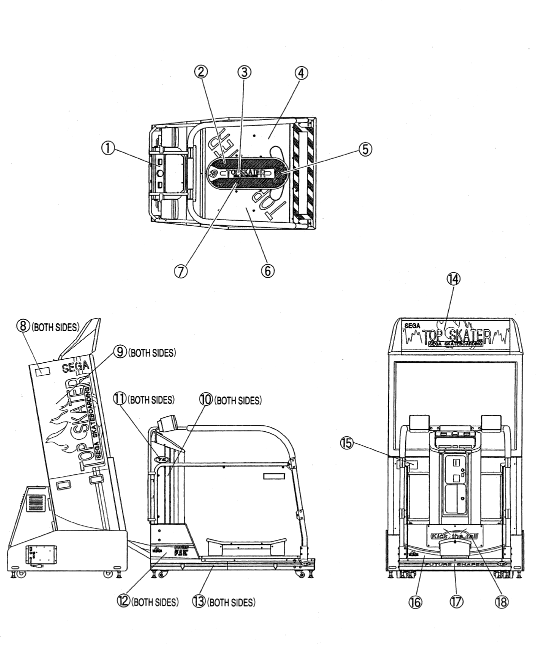
58
15 . DESIGN RELATED PARTS
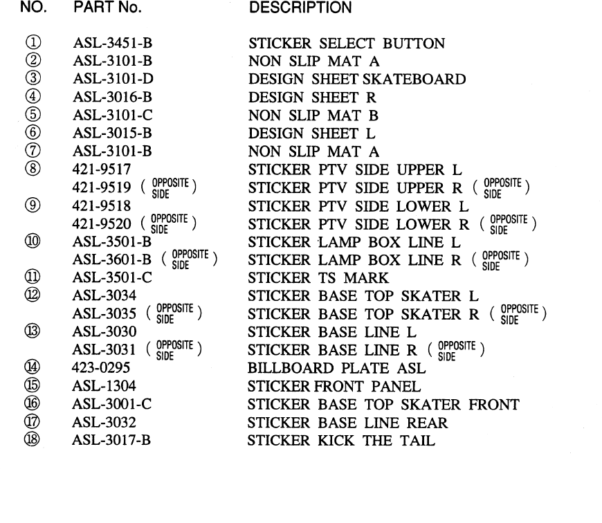
59
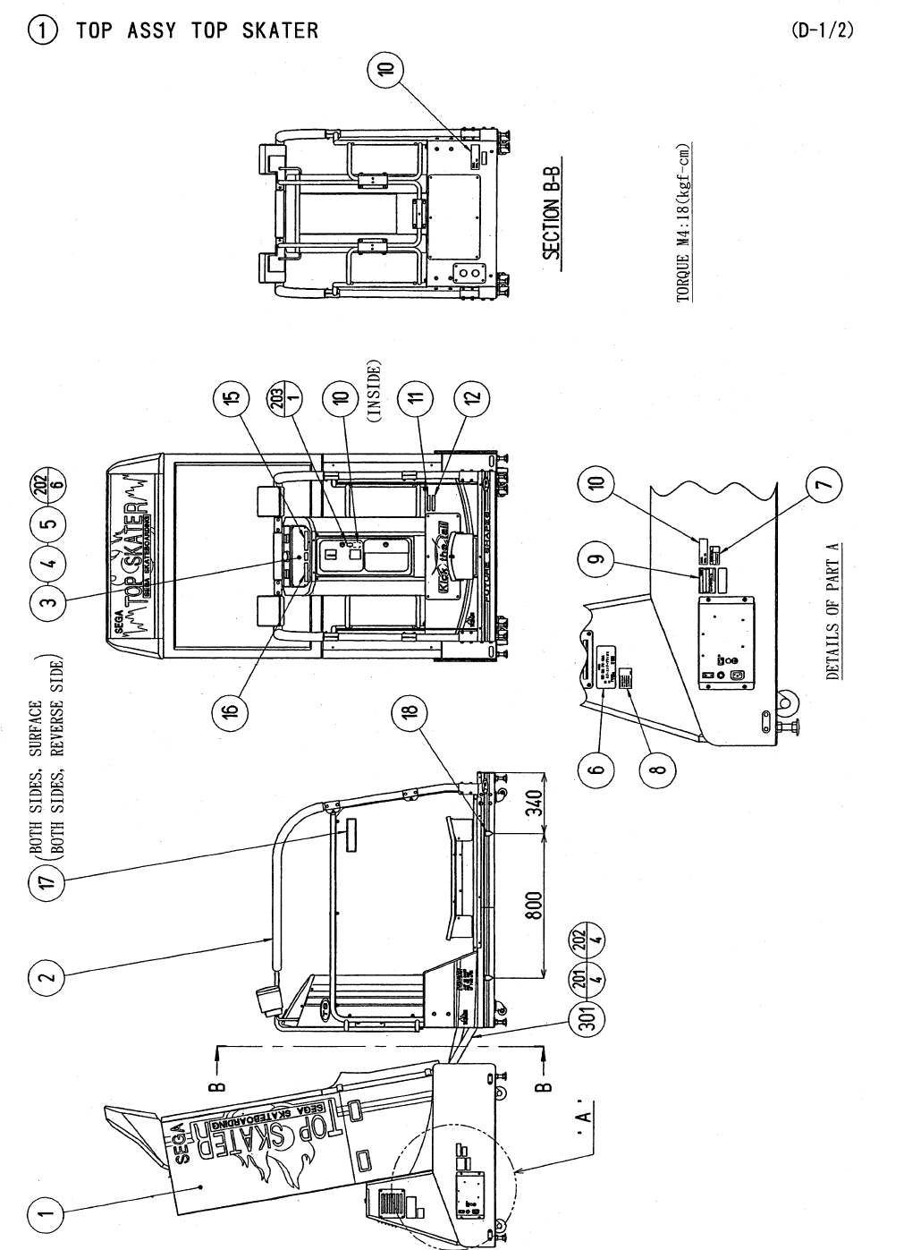
60
16 . PARTS LIST
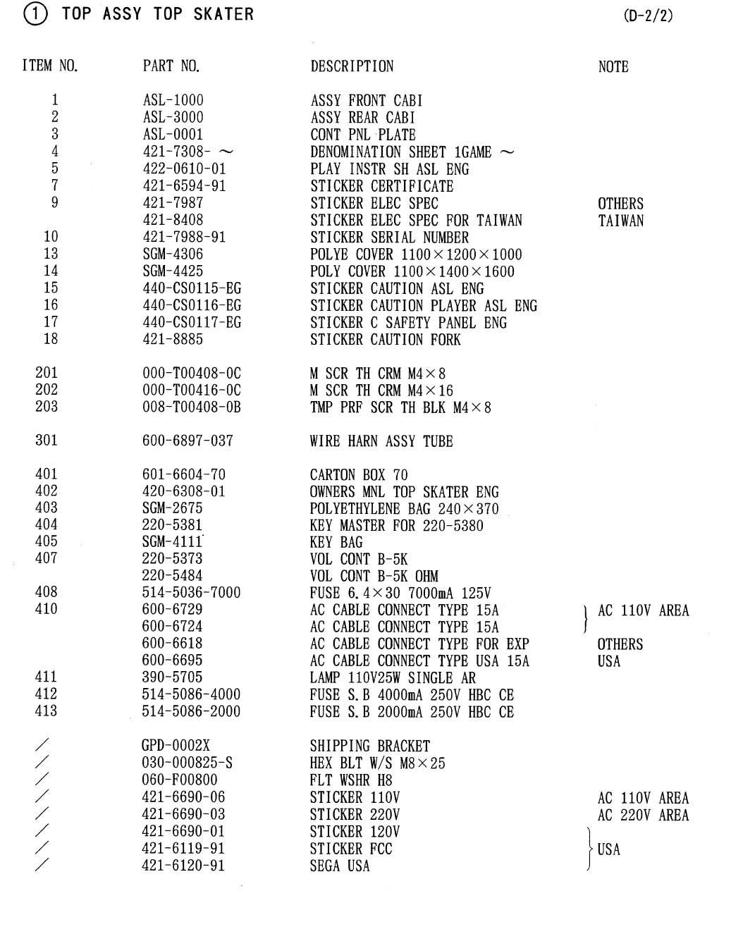
61
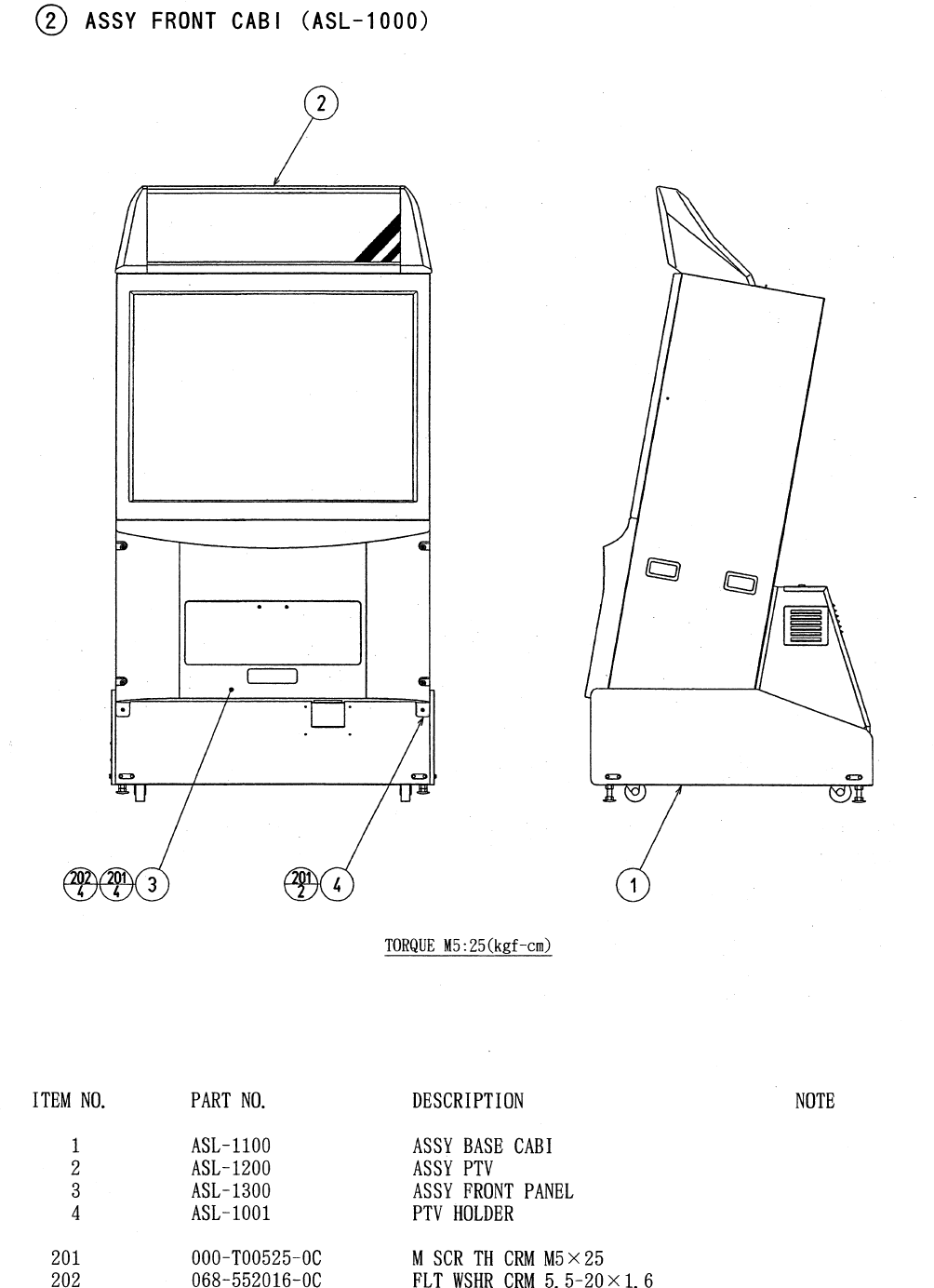
62
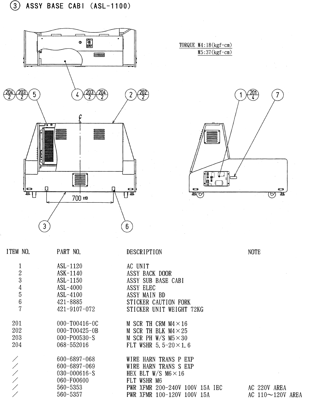
63
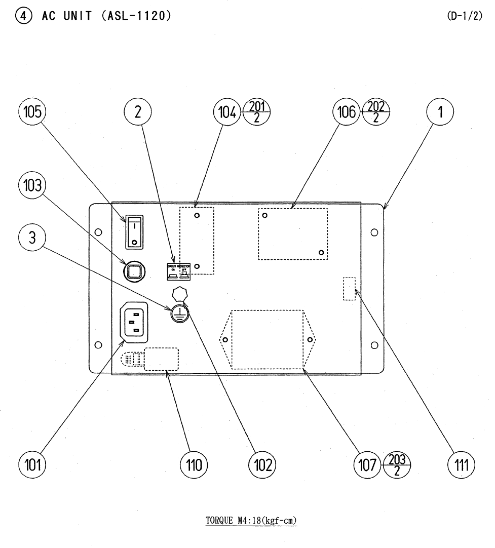
64
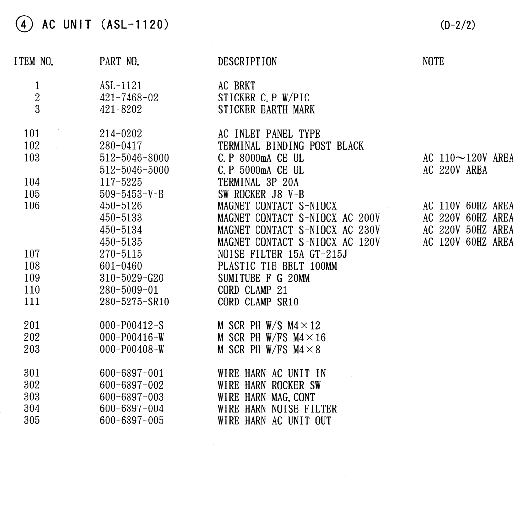
65
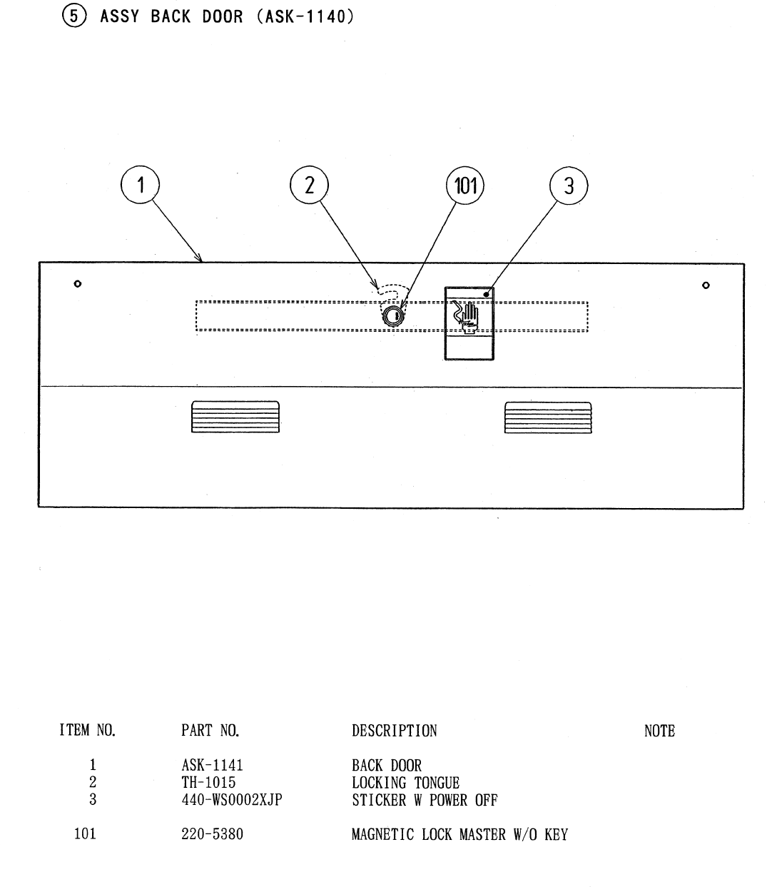
66
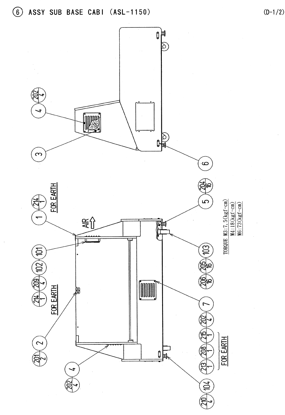
67
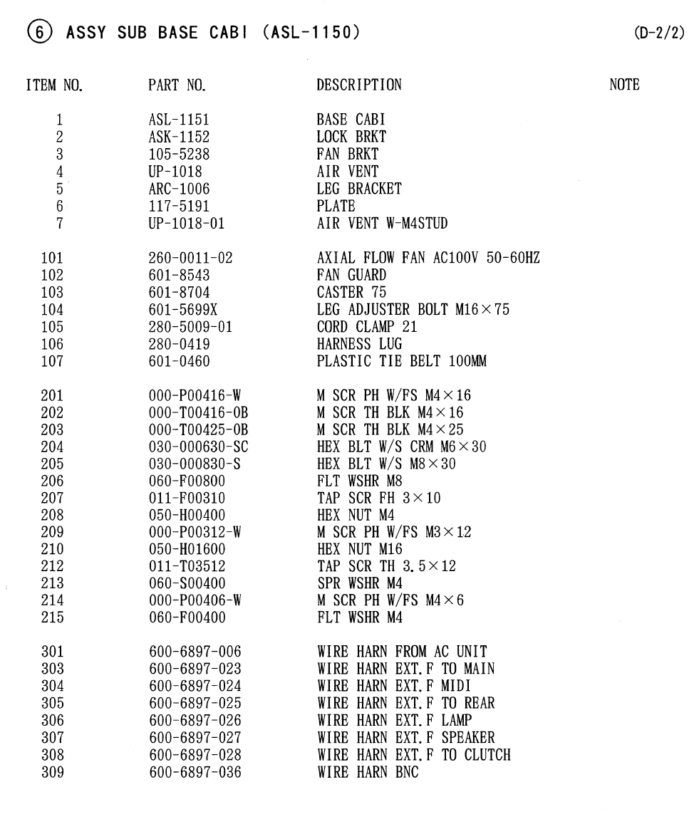
68
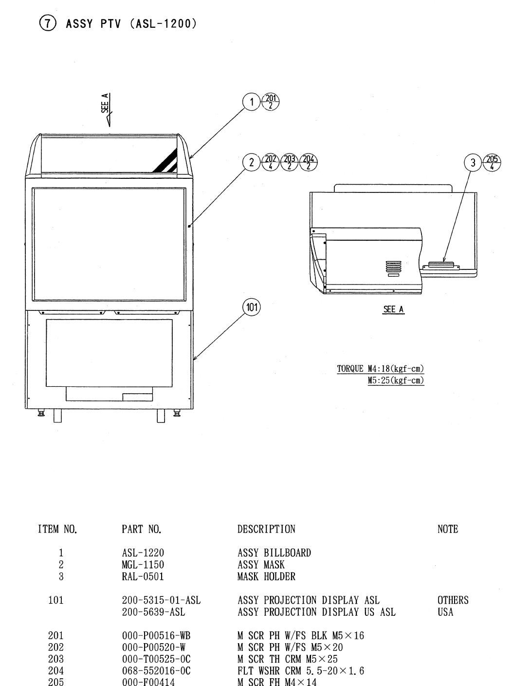
69
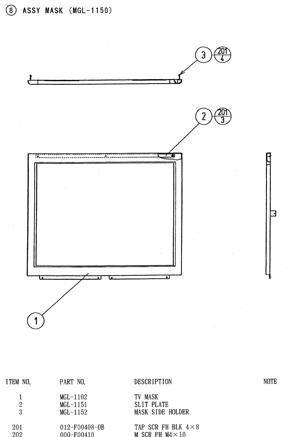
70
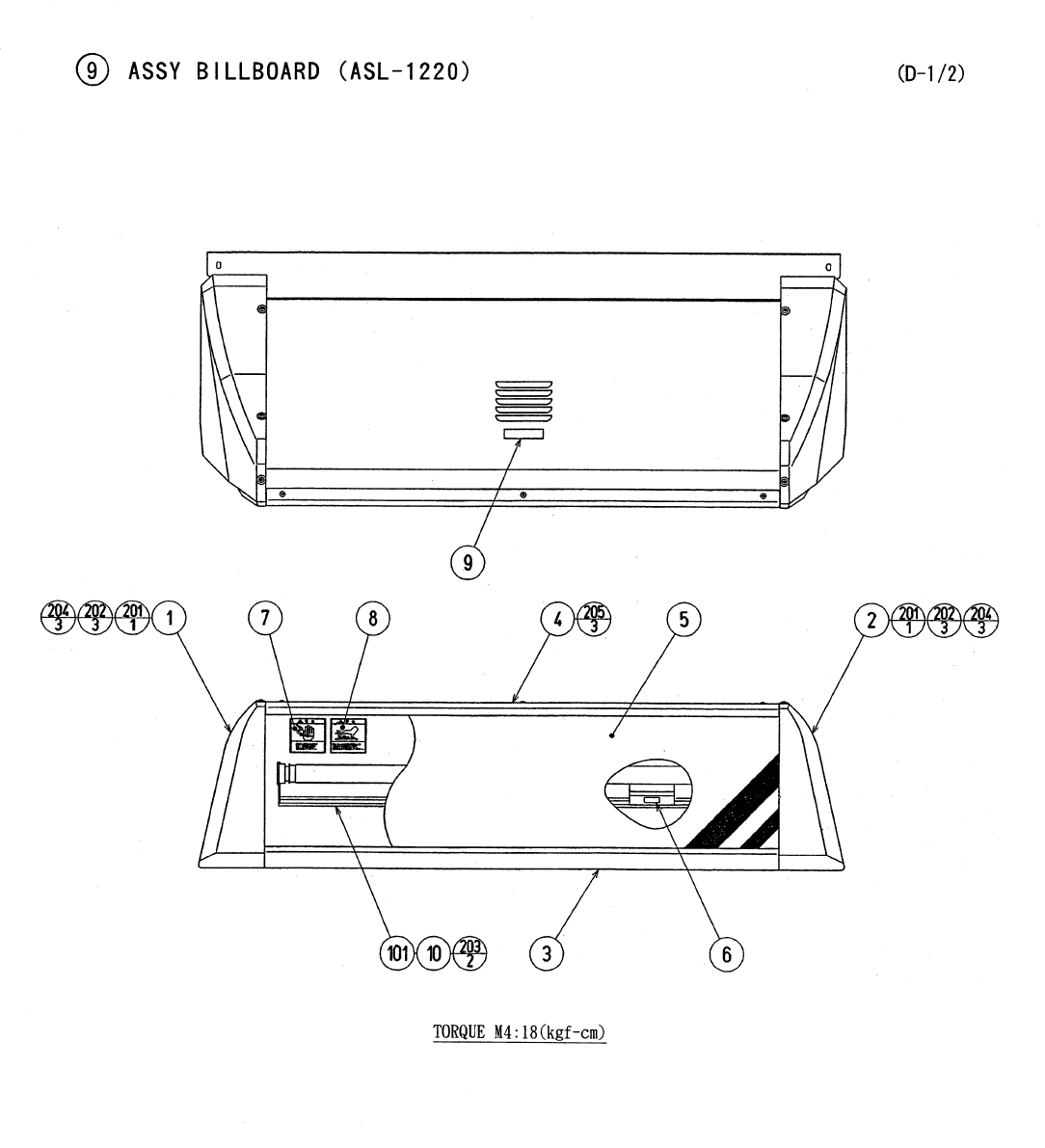
71
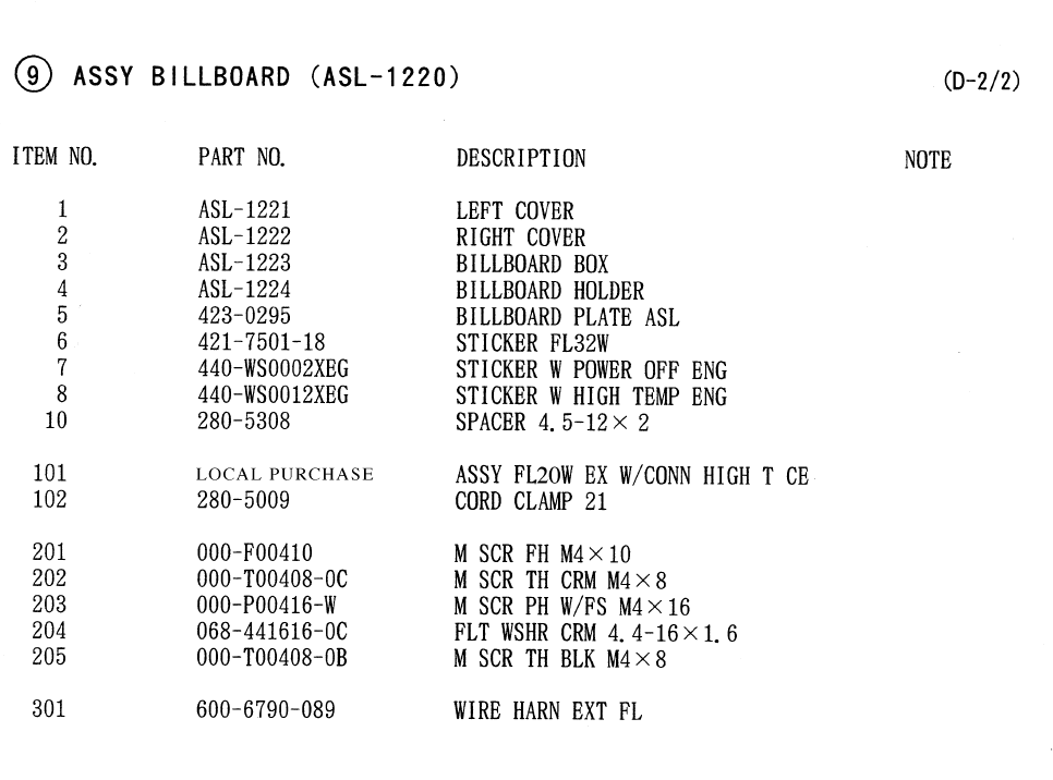
72
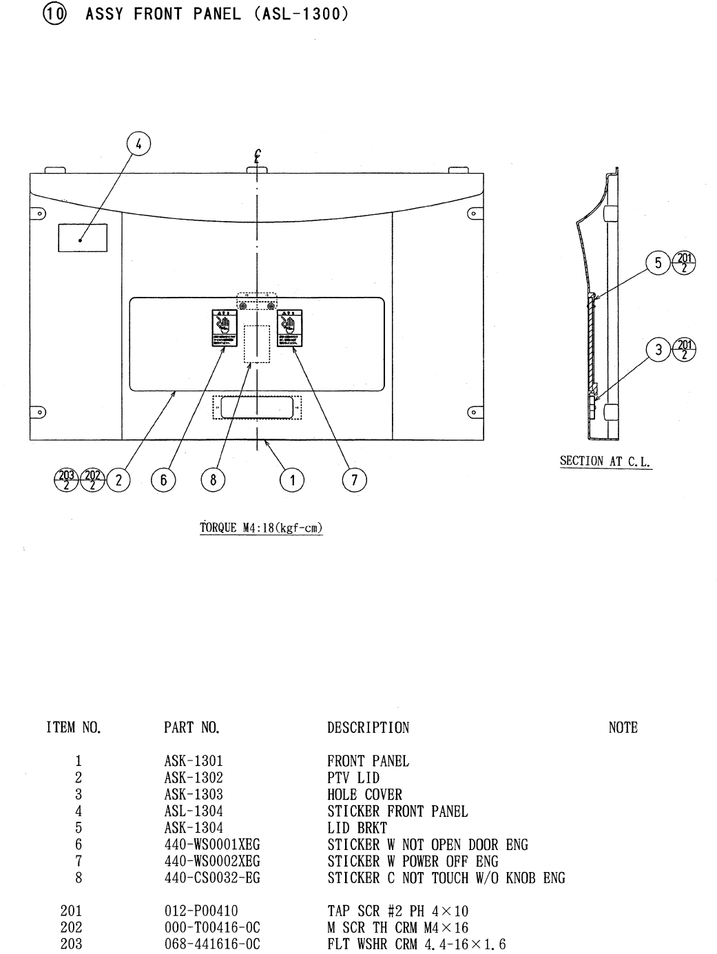
73
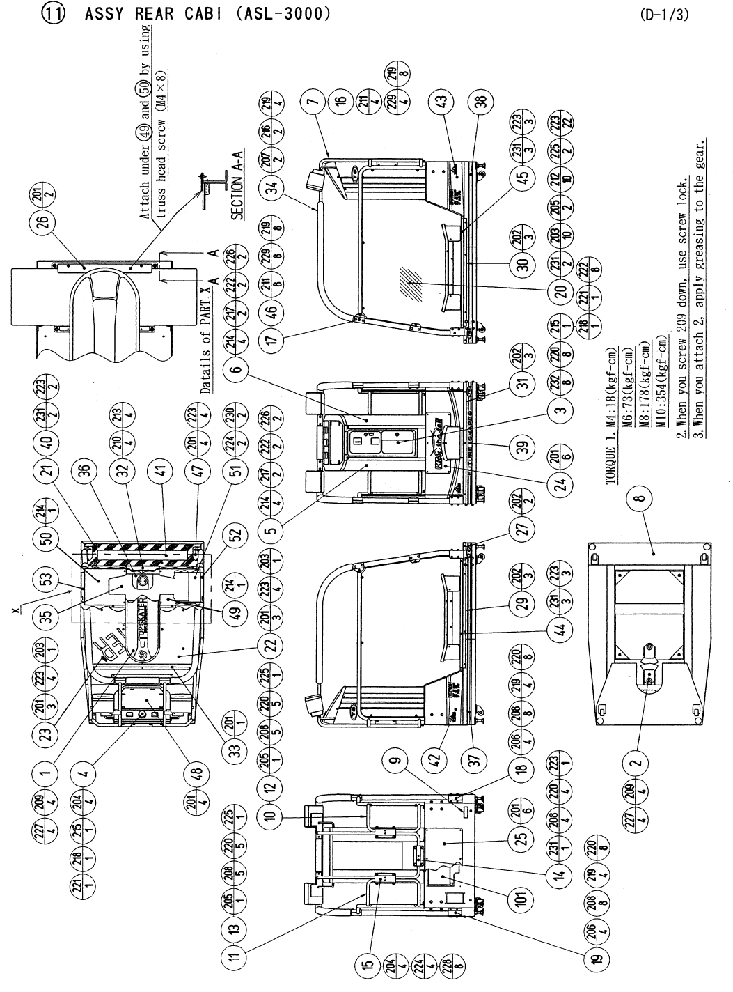
74
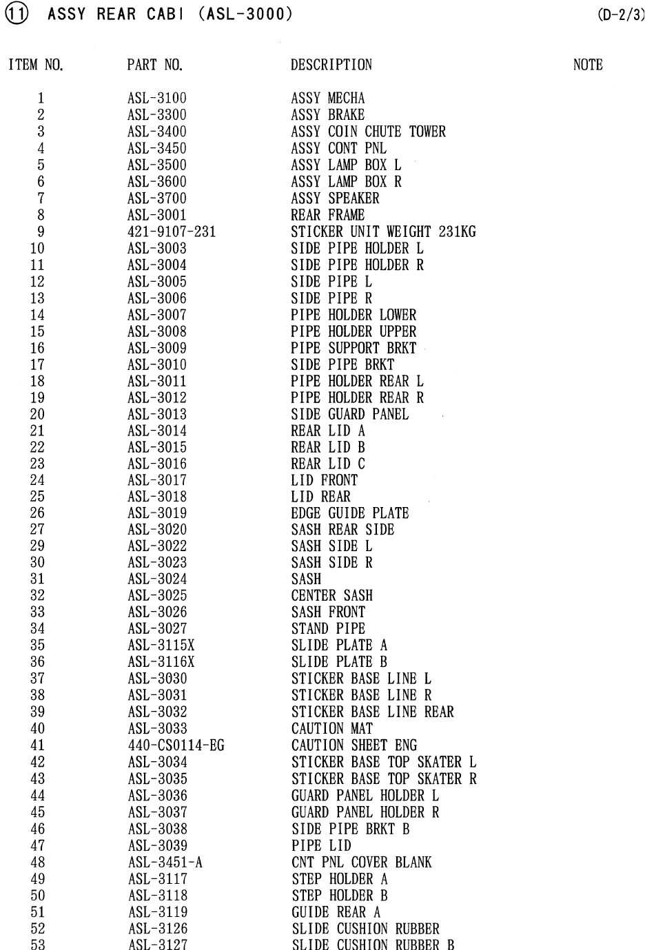
75
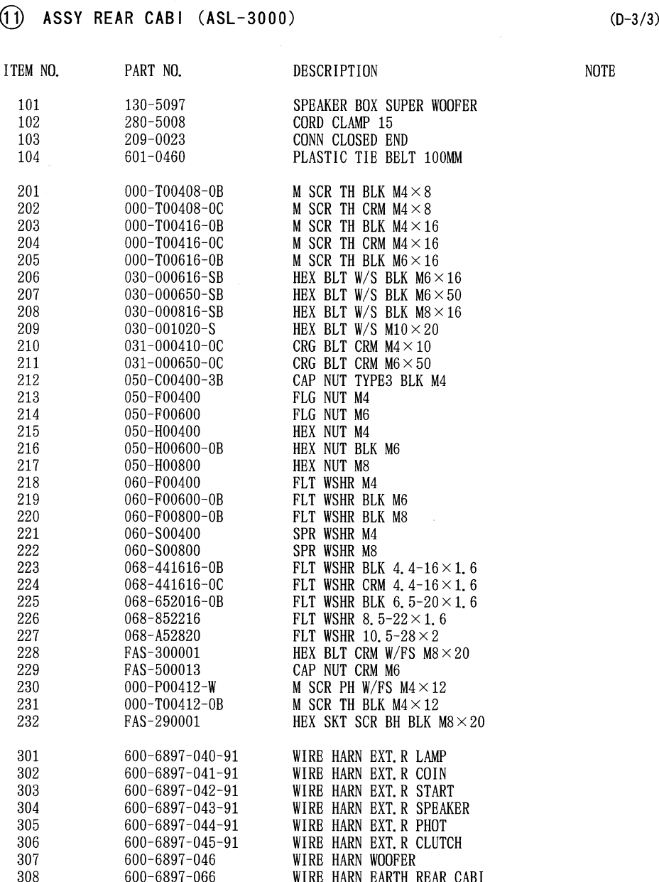
76
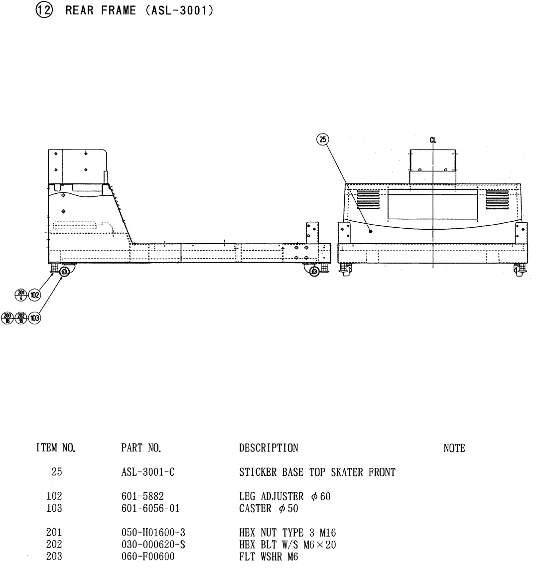
77
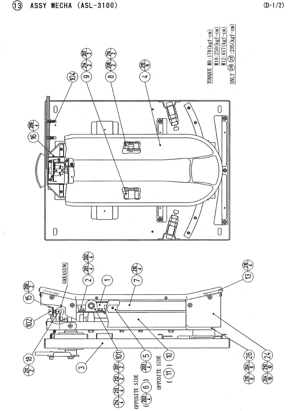
78
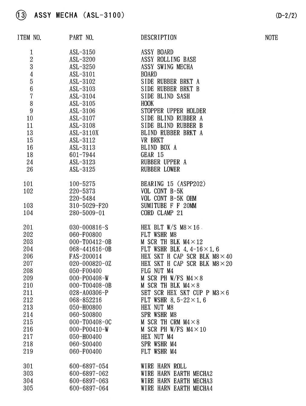
79
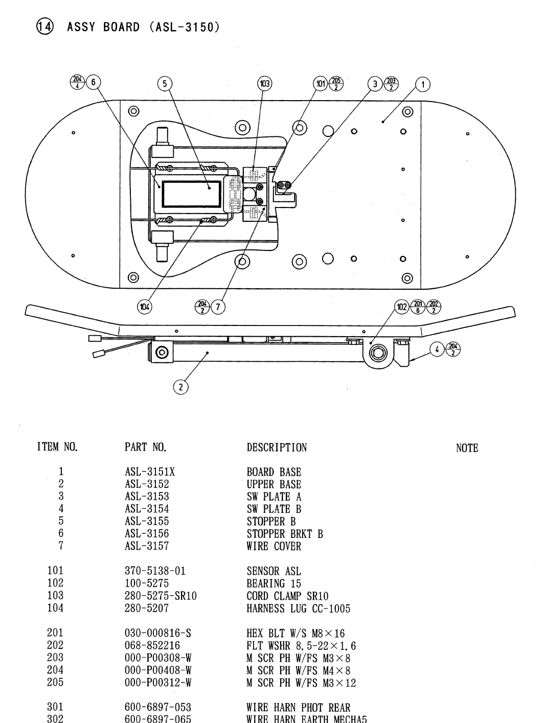
80
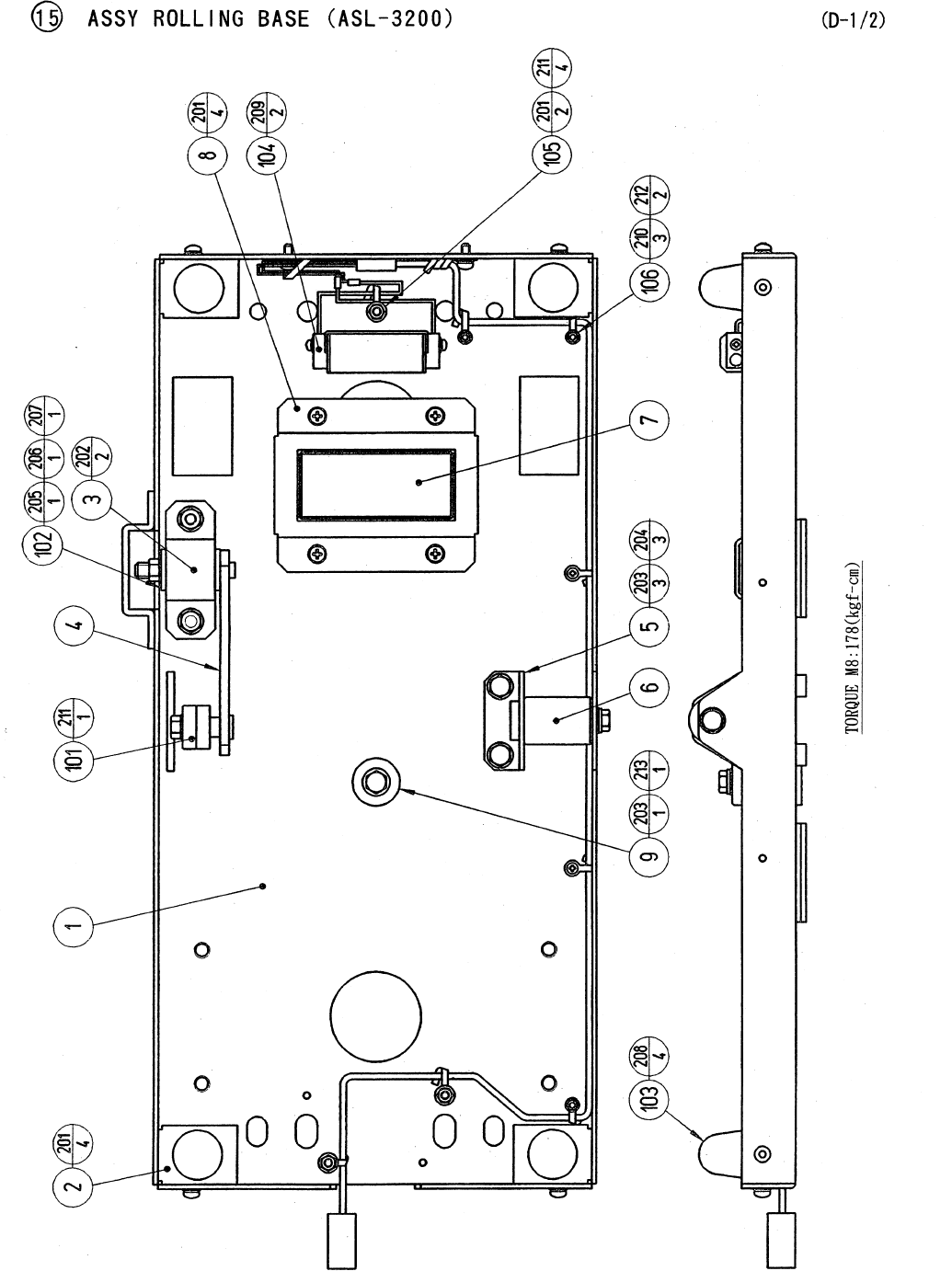
81
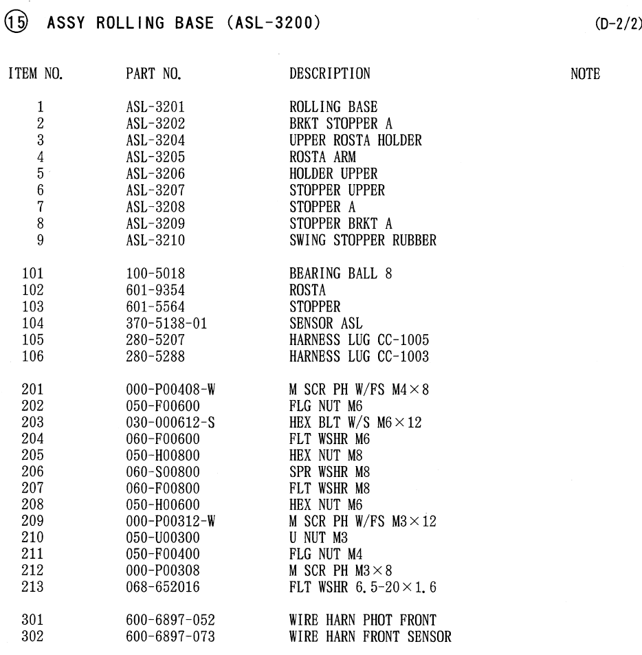
82
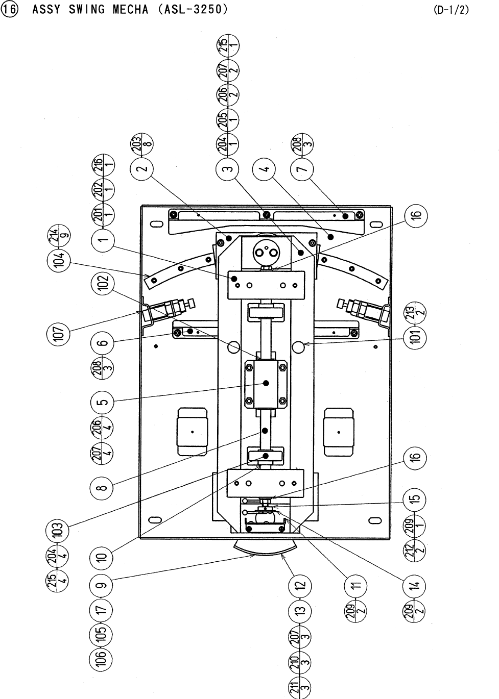
83
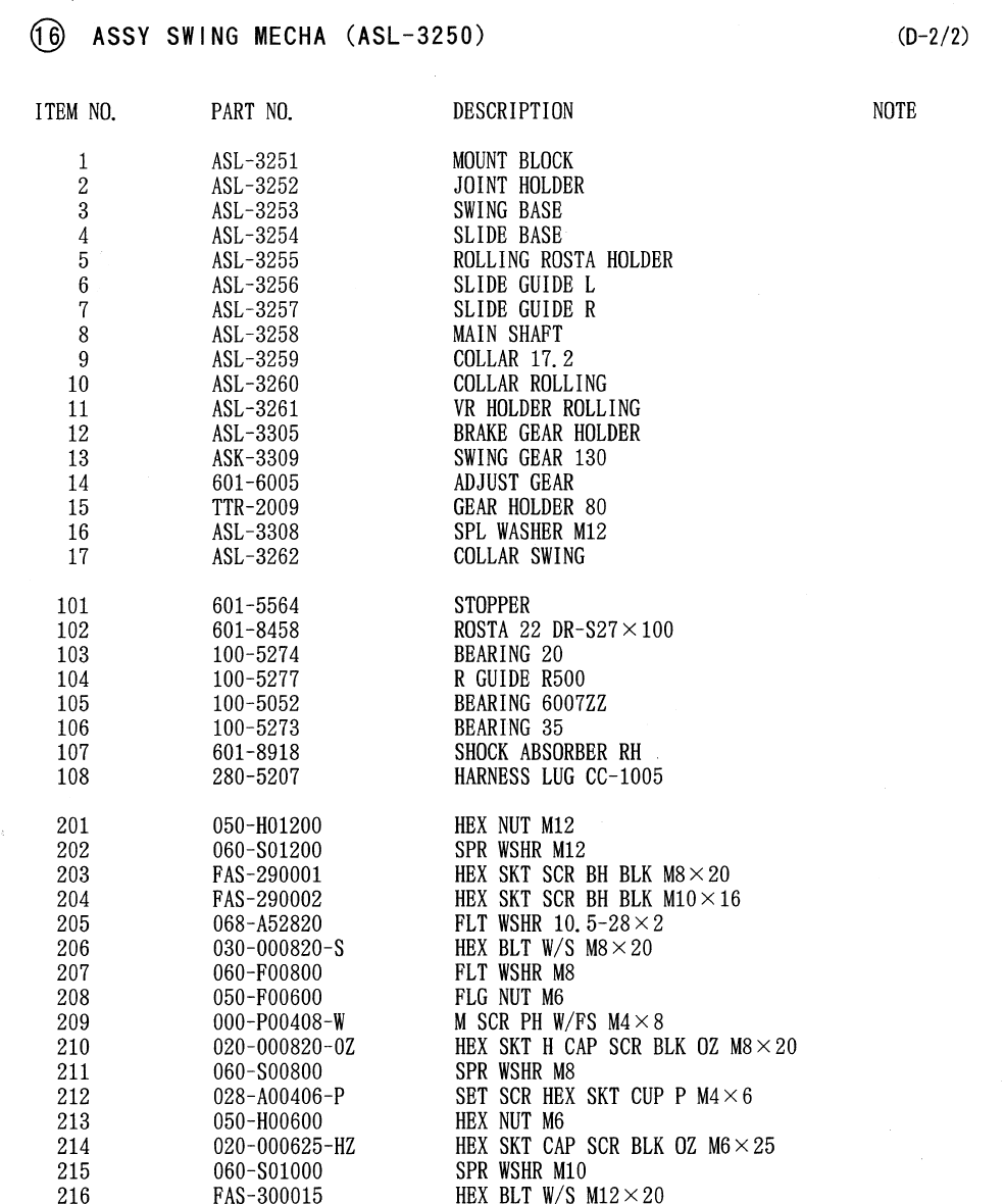
84
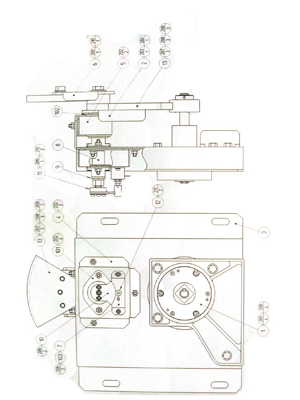
84
www.seuservice.com
85 www.seuservice.com
86
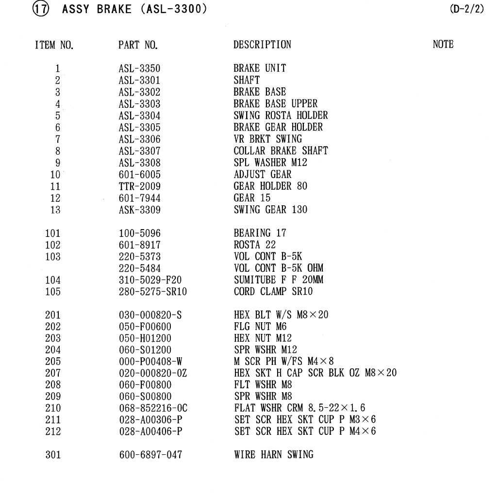
86
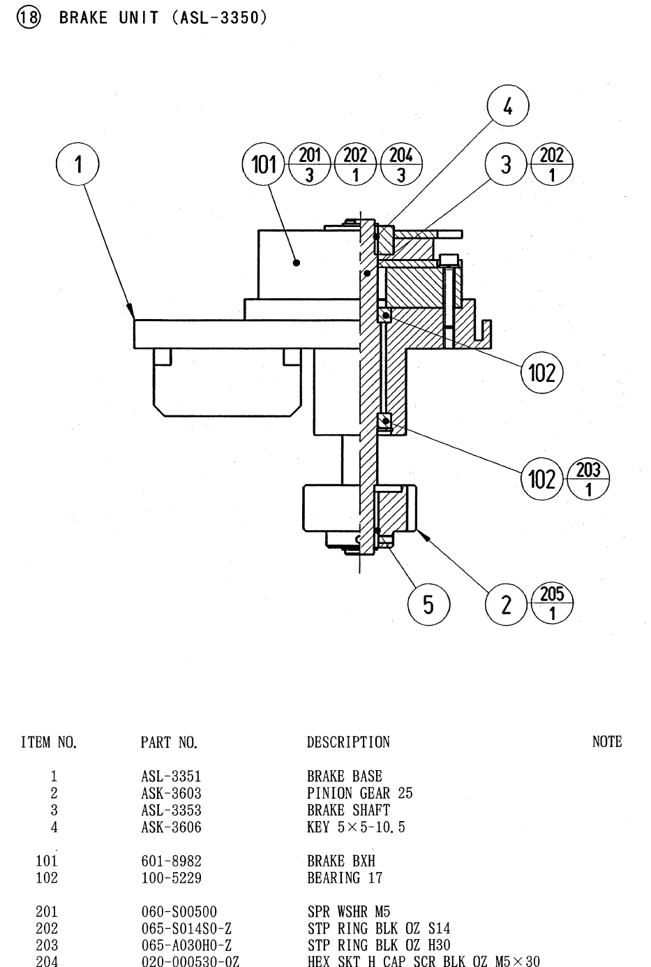
87
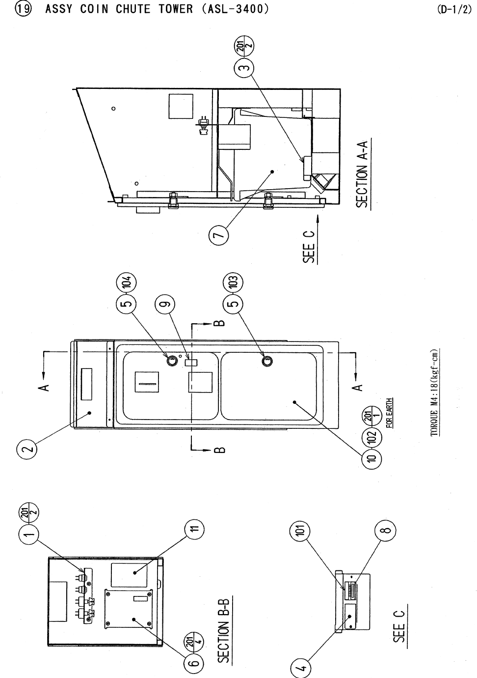
88
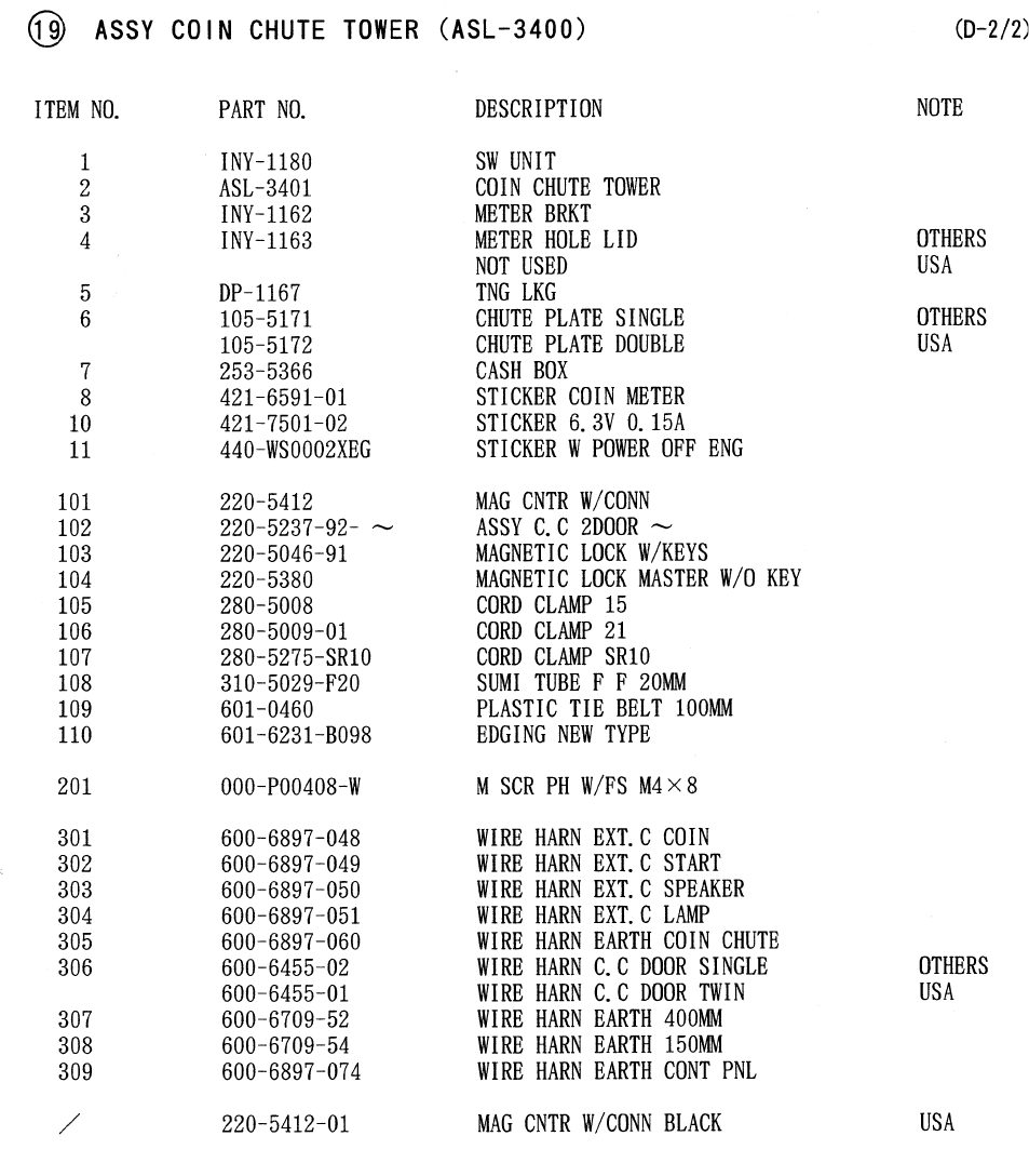
89
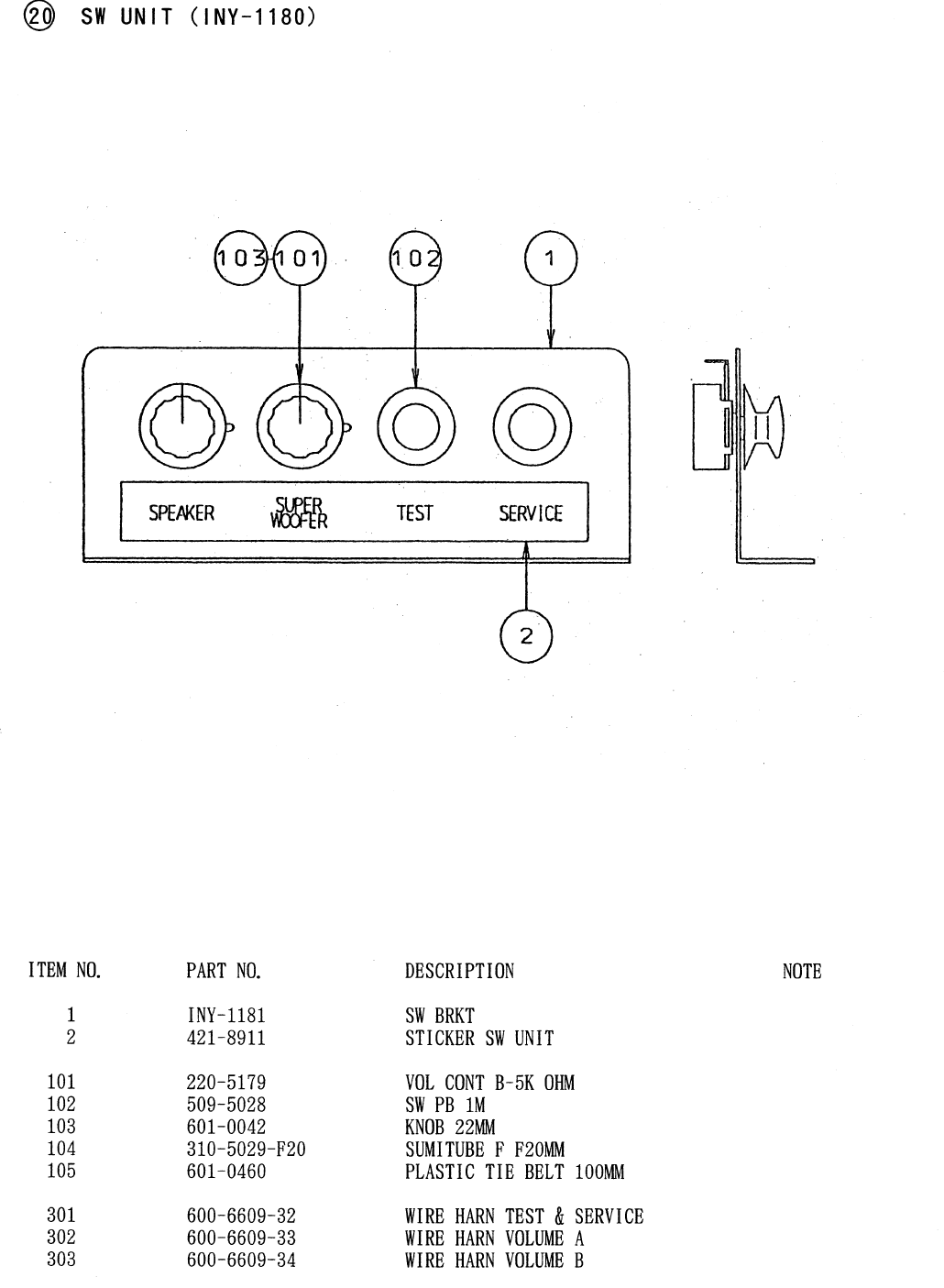
90
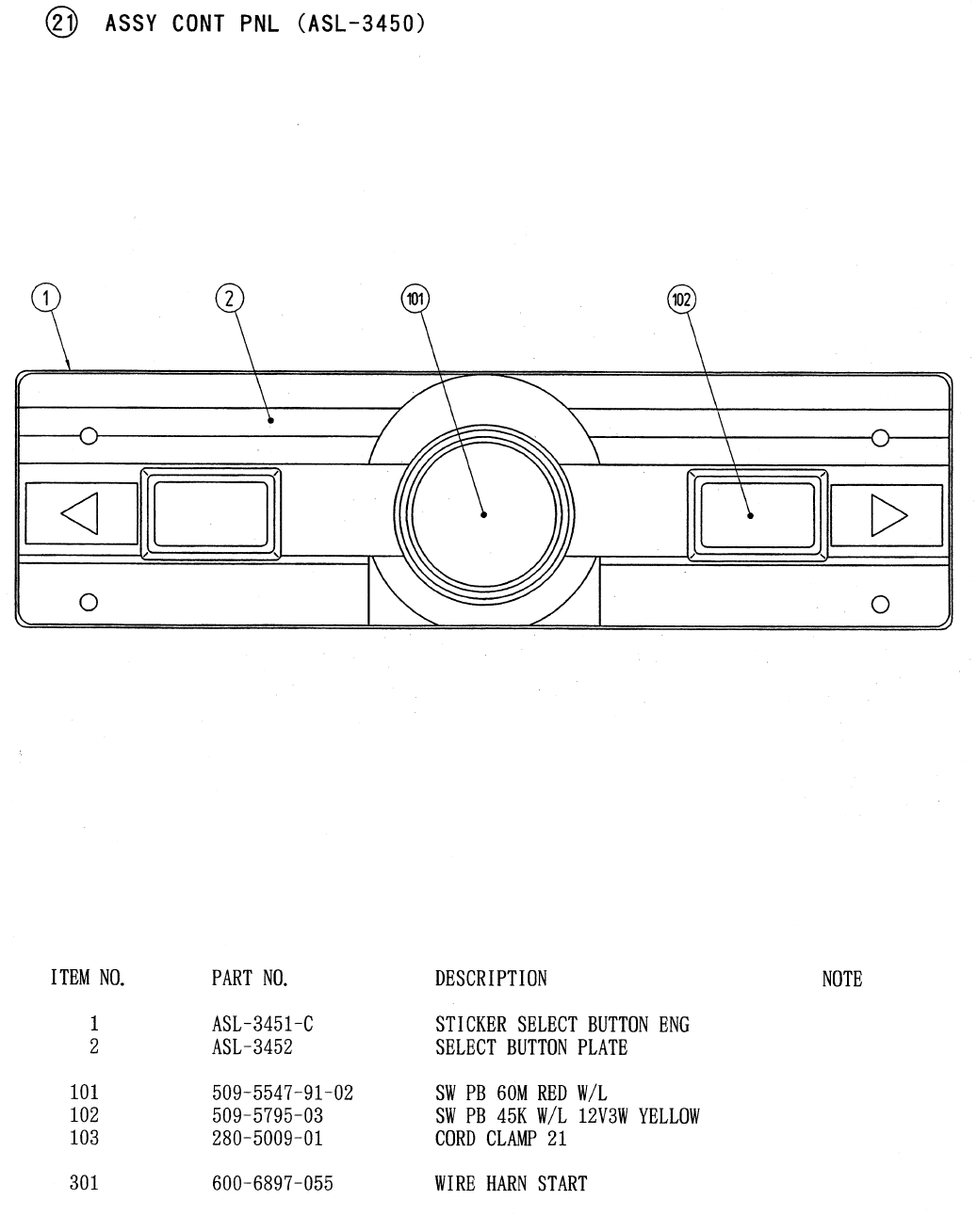
91

92
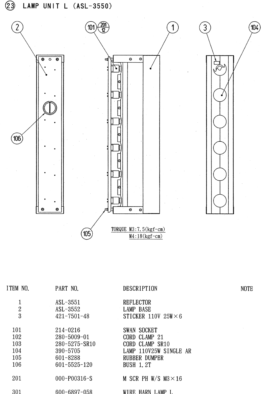
93
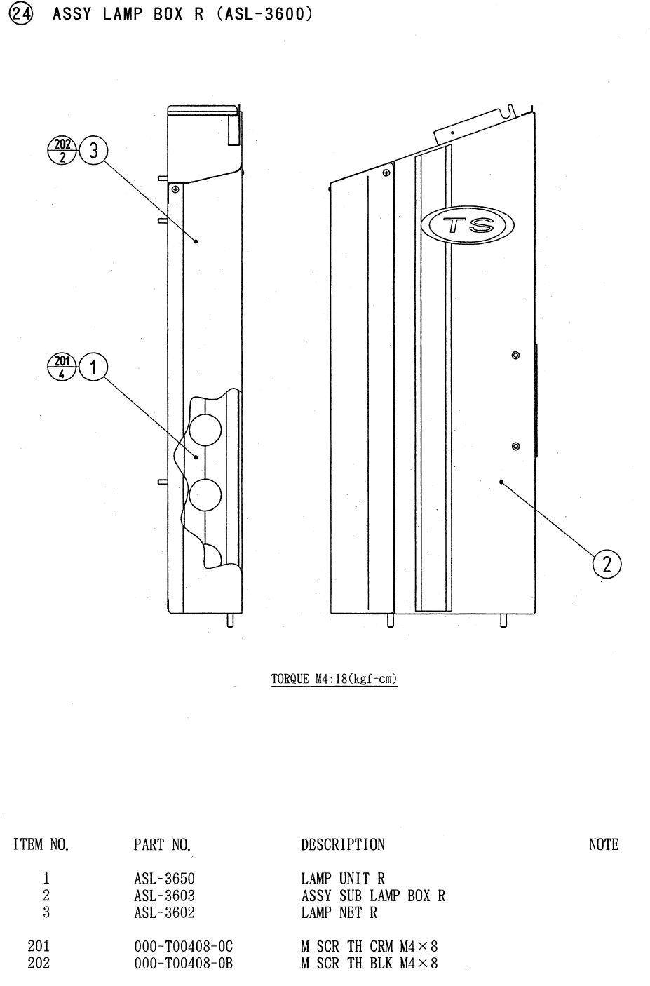
94
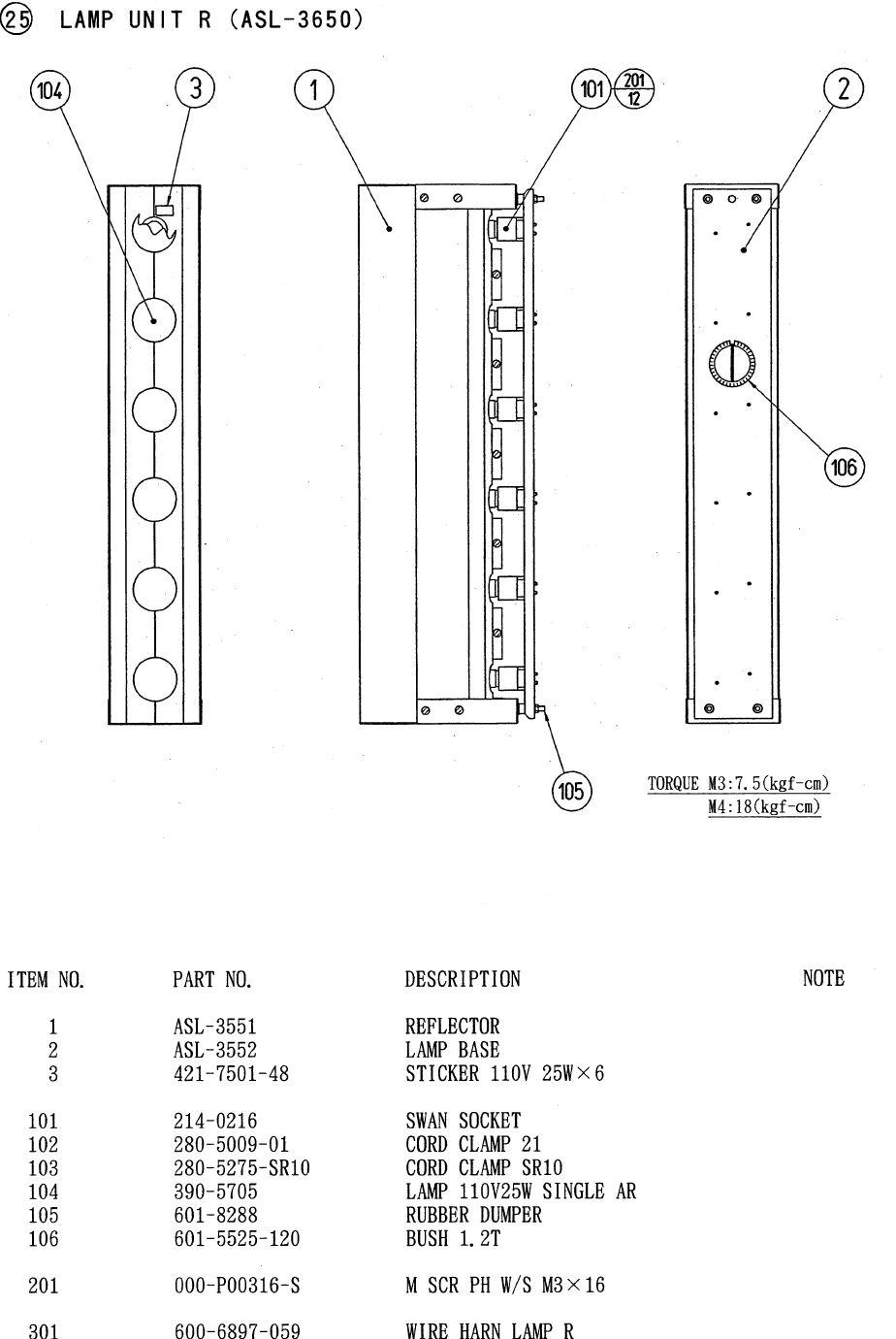
95
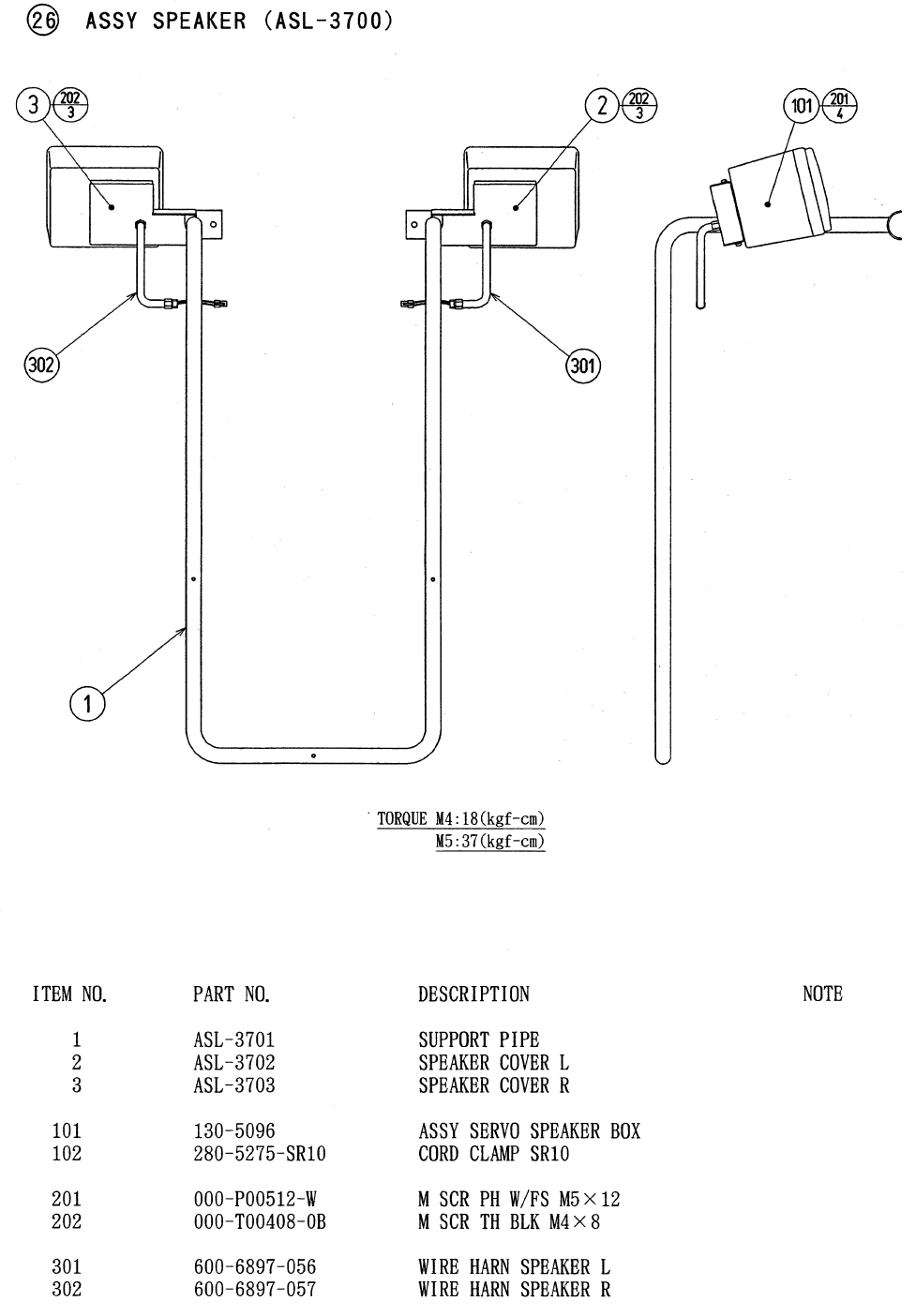
96
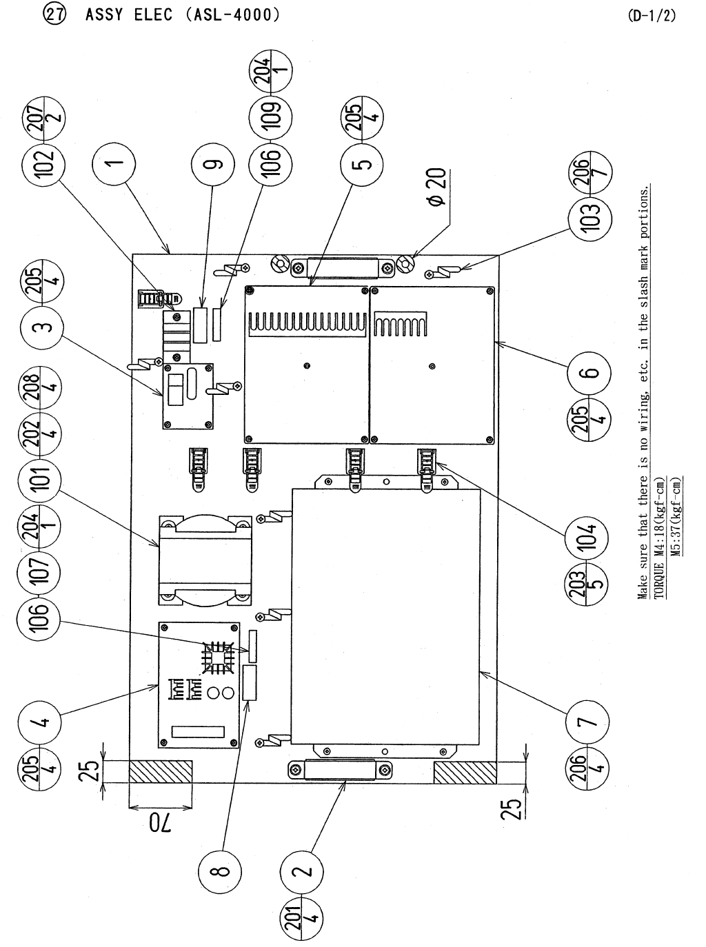
97
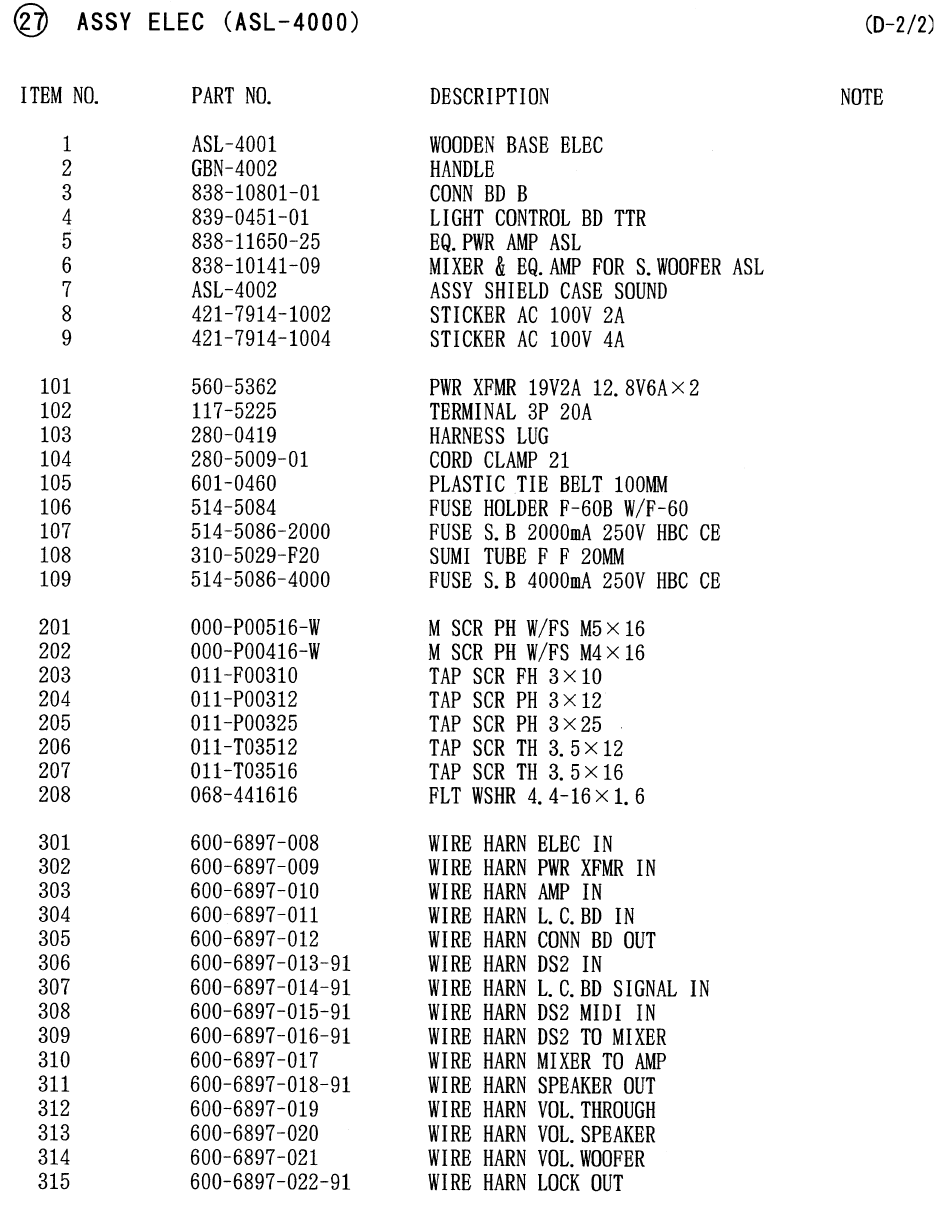
98
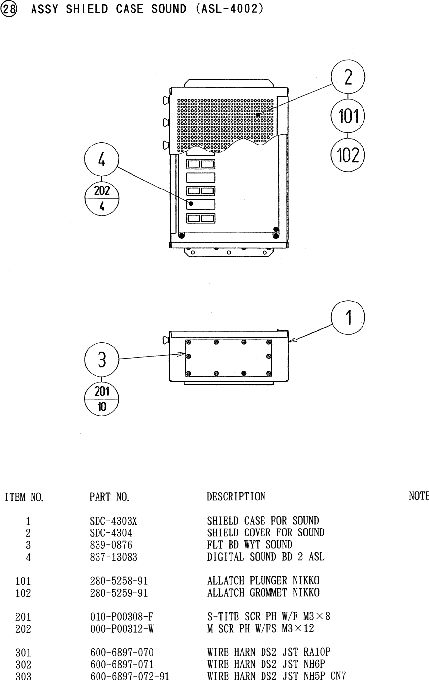
99
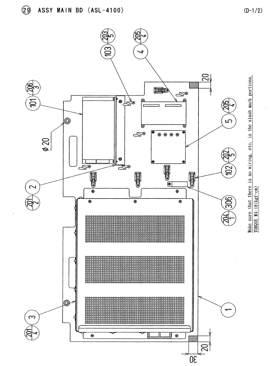
100
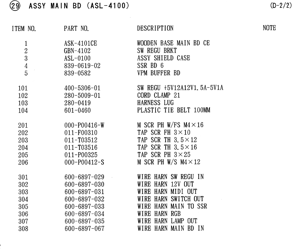
101
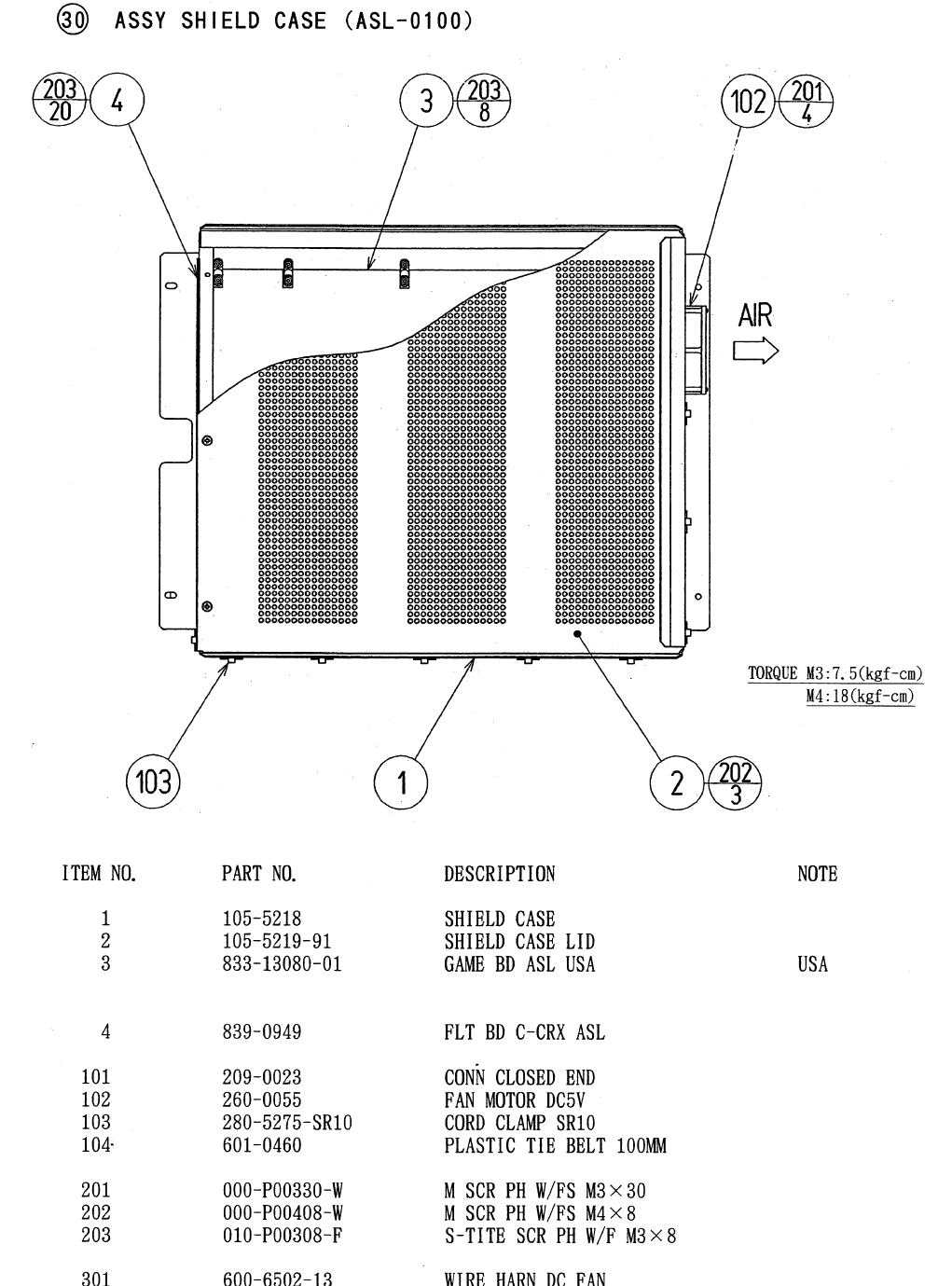
102
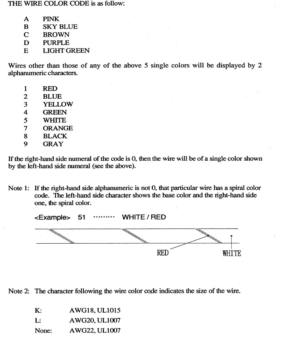
103
17 . WIRE COLOR CODE TABLE

Come see Sega GameWorks Service Department’s Homepage
