Arcade Wave Runner Gp Std Manual Cover User
2013-11-28
User Manual: Arcade Wave Runner Gp Std Manual
Open the PDF directly: View PDF ![]() .
.
Page Count: 79
1ST PRINTING JUNE ‘03
MANUAL NO. 999-1869
Owner’s Manual
SEGA ENTERPRISES, INC. USA
STD Version
www.seuservice.com
Game Code: WRG
VISIT OUR WEBSITE!

BEFORE USING THE PRODUCT, BE SURE TO READ THE FOLLOWING:
To maintain the safety:
To ensure the safe usage of the product, be sure to read the following before using the product. The
following instructions are intended for the users, operators and the personnel in charge of the opera-
tion of the product. After carefully reading and sufciently understanding the warning displays and
cautions, handle the product appropriately. Be sure to keep this manual nearby the product or else-
where convenient for referring to it when necessary.
Herein, explanations which require special attention are enclosed with dual lines. Depending on the
potentially hazardous degrees, the terms of WARNING, CAUTION, etc. are used. Be sure to under-
stand the contents of the displays before reading the text.
Indicates that mishandling the prod-
uct by disregarding this warning
will cause a potentially hazardous
situation which can result in death
or serious injury.
Indicates that mishandling the product
by disregarding this caution will cause
a slight hazardous situation which can
result in personal injury and or material
damage.
For the safe usage of the product, the following pictographs are used:
Indicates “HANDLE WITH CARE.” In order to protect the human body an equipment,
this display is attached to places where the Owner’s Manual and or Service Manual should
be referred to.
Perform work in accordance with the instructions herein stated.
Instructions for work are explained by paying attention to the aspect of accident prevention. Failing to
perform work as per the instructions can cause accidents. In the case where only those who have tech-
nical expertise should perform the work to avoid hazardous situation, the instructions herein state that the
serviceman should perform such work.
Be sure to turn off power before working on the machine.
To prevent electric shock, be sure to turn off power before starting the work in which the worker touches
the interior of the product. If the work is to be performed in the power-on status, the Instruction Manual
herein always states to that effect.
Be sure to ground the Earth Terminal (this, however, is not required in the case where a power cord
with earth is used).
This product is equipped with the Earth Terminal. When installing the product, Connect the Earth Ter-
minal to the “accurately grounded indoor earth terminal” by using an earth wire. Unless the product is
grounded appropriately, the user can be subject to electric shock. After performing repair, etc. for the
Control equipment, ensure that the Earth Wire is rmly connected to the Control equipment.
Ensure that the Power Supply used is equipped with an Earth Leakage Breaker.
This product does not incorporate the Earth Leakage Breaker. Using a power supply which is not
equipped with the Earth Leakage Breaker can cause a re when earth leakage occurs.
Be sure to use fuses which meet the specied rating. (only for the machines which use fuses).
Using fuses exceeding the specied rating can cause a re and electric shock.
WARNING! CAUTION!
Specication changes (removal of equipment, conversion and addition) not designated by SEGA
are not allowed.
The parts of the product include warning labels for safety, covers for personal protection, etc. It is
very hazardous to operate the product by removing parts and or modifying the circuits. Should doors,
lids and protective parts be damaged or lost, refrain from operating the product, and contact where the
product was purchased from or the ofce herein stated. SEGA shall not be held responsible for any
accidents, compensation for damage to a third party, resulting from the specications not designated by
SEGA.
Ensure that the product meets the requirements of appropriate Electrical Specications.
Before installing the product, check for Electrical Specications. SEGA products have a nameplate
on which Electrical Specications are described. Ensure that the product is compatible with the power
supply voltage and frequency requirements of the location. Using any Electrical Specications different
from the designated Specications can cause a re and electric shock.
Install and operate the product in places where appropriate lighting is available, allowing warning
labels to be clearly read.
To ensure safety for the customers, labels and printed instructions describing potentially hazardous situ-
ation are applied to places where accidents can be caused. Ensure that where the product is operated
has sufcient lighting allowing the warnings to be read. If any label is peeled off, apply it again imme-
diately. Please place an order with where the product was purchased from or the ofce herein stated.
When handling the Monitor, be very careful. (Applies only to the product w/monitor.)
Some of the monitor (TV) parts are subject to high tension voltage. Even after running off power, some
portions are still subject to high tension voltage sometimes. Monitor repair and replacement should be
performed only be those technical personnel who have knowledge of electricity and technical expertise.
Be sure to adjust the monitor (projector) properly. (Applies only to the product w/monitor.)
Do not operate the product leaving on-screen ickering or blurring as it is. Using the product with the
monitor not properly adjusted may cause dizziness or a headache to an operator, a player, or the cus-
tomers.
When transporting or reselling this product, be sure to attach this manual to the product.
In the case where commercially available monitors and printers are used in this product, only the con-
tents relating to this product are explained herein. Some commercially available equipment has func-
tions and reactions not stated in this manual. Read this manual together with the specic Instruction
Manual of such equipment.
Descriptions herein contained may be subject to improvement changes without notice.
The contents described herein are fully prepared with due care. However, should any question arise or
errors be found, please contact SEGA.
•
•
INSPECTIONS IMMEDIATELY AFTER TRANSPORTING THE PRODUCT TO THE LOCATION.
Normally, at the time of shipment, SEGA products are in a status allowing for usage immediately after
transporting to the location. Nevertheless, an irregular situation may occur during transportation. Before
turning on power, check the following points to ensure that the product has been transported in a satis-
factory status.
Are there any dented portions or defects (cuts, etc.) on the external surfaces of the cabinet?
Are Casters and Adjusters, damaged?
Do the power supply voltage and frequency requirements meet with those of the location?
Are all wiring connectors correctly and securely connected? Unless connected in the correct direction,
connector connections can not be made accurately. Do not insert connectors forcibly.
Do power cords have cuts and dents?
Do the fuses used meet specied rating? Is the Circuit Protector in an energized status?
Are all accessories available?
Can all Doors and Lids be opened with the Accessory keys? Can Doors and Lids be rmly closed?

TABLE OF CONTENTS
BEFORE USING THE PRODUCT, BE SURE TO READ THE FOLLOWING:
TABLE OF CONTENTS
INTRODUCTION OF THE OWNER’S MANUAL
1. HANDLING PRECAUTIONS ..........................................................................................
2. PRECAUTIONS CONCERNING INSTALLATION LOCATION ...................................
3. OPERATION .....................................................................................................................
4. NAME OF PARTS .............................................................................................................
5. ACCESSORIES .................................................................................................................
6. ASSEMBLING AND INSTALLATION ............................................................................
7. PRECAUTIONS TO BE HEEDED WHEN MOVING THE MACHINE ........................
8. CONTENTS OF GAME ....................................................................................................
9. EXPLANATION OF TEST AND DATA DISPLAY .........................................................
10. COIN SELECTOR ............................................................................................................
11. MONITOR ........................................................................................................................
12. PERIODIC INSPECTION TABLE ..................................................................................
13. TROUBLESHOOTING ....................................................................................................
14. GAME BOARD ................................................................................................................
15. DESIGN RELATED PARTS ...........................................................................................
16. COMMUNICATION PLAY .............................................................................................
17. PARTS ...............................................................................................................................
17. WIRE COLOR CODE TABLE ........................................................................................
18. WIRING DIAGRAM .......................................................................................................
1 - 2
3 - 4
5 - 7
8
9 - 10
11 - 18
19 - 20
21 - 25
26 - 43
44 - 45
46 - 47
48
49 - 52
53 - 54
55
56 - 60
61 - 64
65
XXX
SPECIFICATIONS
INTRODUCTION OF THE OWNERS MANUAL
This Owner's Manual is intended to provide detailed descriptions together with all the
necessary information covering the general operation of electronic assemblies, electrome-
chanicals, servicing control, spare parts, etc. as regards the product,
WAVERUNNER GP STANDARD VERSION.
This manual is intended for the owners, personnel and managers in charge of operation
of the product. Operate the product after carefully reading and sufciently understand-
ing the instructions. If the product fails to function satisfactorily, non-technical personnel
should under no circumstances touch the internal system. Please contact where the prod-
uct was purchased from.
SEGA AMUSEMENTS USA, INC./CUSTOMER SERVICE
45133 Industrial Drive, Fremont, California 94538, U.S.A.
Phone : (415) 701-6580
Fax : (415) 701-6594
Use of this product is unlikely to cause physical injuries or damages to property. However,
where special attention is required this is indicated by a thick line, the word "IMPORTANT"
and its sign in this manual.
Indicates that mishandling the product by disregarding this display can cause the
product's intrinsic performance not to be obtained, resulting in malfunctioning.
Installation Space : 38.25 inches wide X 84.5 inches deep
Height : 77.5 inches
Width : 30.25 inches
Length : 76.5 inches
Weight : 550 lbs
Power, maximum current : 420 W 3.5 A (AC 120V 60 Hz AREA)
MONITOR : 29 inch supplied by Wells Gardner
model #wgm-2972XX
STOP
IMPORTANT!
DEFINITION OF LOCATION MAINTENANCE MAN AND SERVICEMAN
Non-technical personnel who do not have technical knowledge and expertise should
refrain from performing such work that this manual requires the location's main-
tenance man or a serviceman to carry out, or work which is not explained in this
manual. Failing to comply with this instruction can cause a severe accident such
as electric shock.
Ensure that parts replacement, servicing & inspections, and troubleshooting are performed by the
location's maintenance man or the serviceman. It is instructed herein that particularly hazardous work
should be performed by the serviceman who has technical expertise and knowledge.
The location's maintenance man and serviceman are herein dened as follows:
"Location's Maintenance Man" :
Those who have experience in the maintenance of amusement equipment and vending machines, etc.,
and also participate in the servicing and control of the equipment through such routine work as equip-
ment assembly and installation, servicing and inspections, replacement of units and consumables, etc.
within the Amusement Facilities and or locations under the management of the Owner and Owner's
Operators of the product.
Activities of Location's Maintenance Man :
Assembly & installation, servicing & inspections, and replacement of units & consumables as regards
amusement equipment, vending machines, etc.
Serviceman :
Those who participate in the designing, manufacturing, inspections and maintenance service of the
equipment at an amusement equipment manufacturer.
Those who have technical expertise equivalent to that of technical high school graduates as regards
electricity, electronics and or mechanical engineering, and daily take part in the servicing & control
and repair of amusement equipment.
Serviceman's Activities :
Assembly & installation and repair & adjustments of electrical, electronic and mechanical parts of
amusement equipment and vending machines.
WARNING!
LISTED
U
L
®
5K92
AMUSEMENT MACHINE
NOTES:
www.seuservice.com
1
1. HANDLING PRECAUTIONS
When installing or inspecting the machine, be very careful of the following points and pay attention to
ensure that the player can enjoy the game safely.
Non-compliance with the following points or inappropriate handling running counter to the cautionary
matters herein stated can cause personal injury or damage to the machine.
• Before performing work, be sure to turn power off. Performing the work with-
out turning power off can cause an electric shock or short circuit. In the case
work should be performed in the status of power on, this manual always states
to that effect.
• To avoid electric shock or short circuit, do not plug in or unplug quickly.
• To avoid electric shock, do not plug in or unplug with a wet hand.
• Do not expose Power Cords and Earth Wires on the surface, (oor, passage,
etc.). If exposed, the Power Cords and Earth Wires are susceptible to damage.
• Damaged cords and wires can cause electric shock or short circuit.
To avoid causing a re or electric shock, do not put things on or damage Power
Cords.
• When or after installing the product, do not unnecessarily pull the power cord.
If damaged, the power cord can cause a re or electric shock.
In case the power cord is damaged, ask for replacement through where the prod-
uct was purchased from or the ofce herein stated. Using the cord as is dam-
aged can cause re, electric shock or leakage.
• Be sure to perform grounding appropriately. Inappropriate grounding can cause
an electric shock.
• Be sure to use fuses meeting specied rating. Using fuses exceeding the speci-
ed rating can cause a re or electric shock.
• Completely make connector connections for IC BD and others. Insufcient
insertion can cause an electric shock.
• Specication changes, removal of equipment, conversion and/or addition, not
designated by SEGA are not permitted.
• Failure to observe this may cause a re or an electric shock. Non-compliance
with this instruction can have a bad inuence upon physical conditions of the
players or the lookers-on, or result in injury during play.
• SEGA shall not be held responsible for damage, compensation for damage to a
third party, caused by specication changes not designated by SEGA.
Be sure to perform periodic maintenance inspections herein stated.
WARNING!

2
www.seuservice.com
www.seuservice.com
3
For the IC board circuit inspections, only the logic tester is allowed. The use of a
multiple-purpose tester is not permitted, so be careful in this regard.
The Projector is employed for this machine. The Projector's screen is susceptible
to damage, therefore, be very careful when cleaning the screen. For details, refer to
PROJECTOR.
Some parts are the ones designed and manufactured not specically for this game
machine. The manufacturers may discontinue, or change the specications of, such
general-purpose parts. If this is the case, Sega cannot repair or replace a failed
game machine whether or not a warranty period has expired.
STOP
IMPORTANT!
2
www.seuservice.com
www.seuservice.com
3
2. PRECAUTIONS CONCERNING INSTALLATION LOCATION
This product is an indoor game machine. Do not install it outside. Even indoors, avoid
installing in places mentioned below so as not to cause a re, electric shock, injury
and or malfunctioning.
Places subject to rain or water leakage, or places subject to high humidity in the
proximity of an indoor swimming pool and or shower, etc.
Places subject to direct sunlight, or places subject to high temperatures in the prox-
imity of heating units, etc.
Places lled with inammable gas or vicinity of highly inammable/volatile chemi-
cals or hazardous matter.
Dusty places.
Sloped surfaces.
Places subject to any type of violent impact.
Vicinity of anti-disaster facilities such as re exits and re extinguishers.
The operating (ambient) temperature range is from 5˚ to 30˚.
Be sure to check the Electrical Specications.
Ensure that this product is compatible with the location's power supply, voltage and
frequency requirements.
A plate describing Electrical Specications is attached to the product.
Non-compliance with the Electrical Specications can cause a re and electric
shock.
This product requires the Breaker and Earth Mechanisms as part of the location
facilities. Using them in a manner not independent can cause a re and electric
shock.
Ensure that the indoor wiring for the power supply is rated at 15A or higher (AC
single phase 100 ~ 120V area), and 8A or higher (AC 220 ~ 240V area). Non-com-
pliance with the Electrical Specications can cause a re and electric shock.
Be sure to independently use the power supply equipped with the Earth Leakage
Breaker. Using a power supply without the Earth Leakage Breaker can cause an
outbreak of re when earth leakage occurs.
Putting many loads on one electrical outlet can cause generation of heat and a re
resulting from overload.
When using an extension cord, ensure that the cord is rated at 15A or higher (AC
100 ~ 120V area) and 8A or higher (AC 220 ~ 240V area). Using a cord rated
lower than the specied rating can cause a re and electric shock.
LIMITATIONS OF USAGE REQUIREMENTS
WARNING!
WARNING!
4
www.seuservice.com
www.seuservice.com
5
76.5 in.
Vent approx. 8 in.
30.14 in.
8 in.
FIG. 2
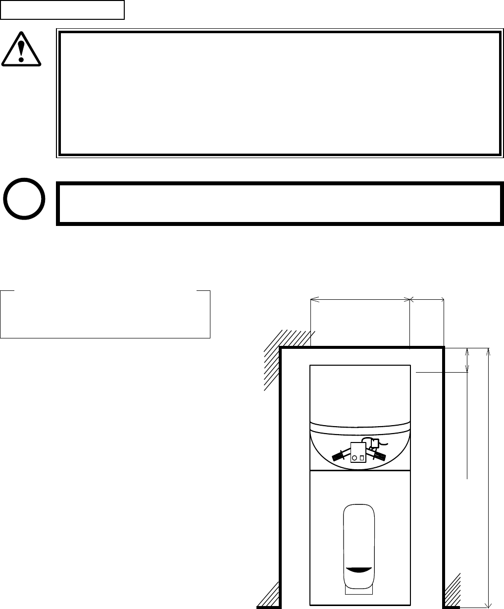
For transporting the machine into the location's building, the minimum necessary di-
mensions of the opening (of doors, etc.) are 31in (W) and 78in (H).
For the operation of this machine, secure a minimum area of 40in (W) X 85in (D).
In order to prevent injury resulting from the falling down accident during game
play, be sure to secure the minimum area for operation.
Be sure to provide sufcient space so as to allow this product's ventilation fan to
function efciently. To avoid machine malfunctioning and a re, do not place any
obstacles near the ventilation opening.
SEGA shall not be held responsible for damage, compensation for damage to a third
party, resulting from the failure to observe this instruction.
OPERATION AREA
Electric current consumption
MAX. 5 A (AC 120V 60 Hz)
WARNING!
STOP
IMPORTANT!
4
www.seuservice.com
www.seuservice.com
5
3. OPERATION
PRECAUTIONS TO BE HEEDED BEFORE STARTING THE OPERATION
To avoid injury and trouble, be sure to constantly give careful attention to the behavior and manner of
the visitors and players.
In order to avoid accidents, check the following before starting the operation:
To ensure maximum safety for the players and the customers, ensure that where
the product is operated has sufcient lighting to allow any warnings to be read.
Operation under insufcient lighting can cause bodily contact with each other,
hitting accident, and or trouble between customers.
Be sure to perform appropriate adjustment of the monitor (projector). For operation
of this machine, do not leave monitor's ickering or deviation as is. Failure to
observe this can have a bad inuence upon the players' or the customers' physical
conditions.
It is suggested to ensure a space allowing the players who feel sick while playing
the game to take a rest.
Check if all of the adjusters are in contact with the
surface. If they are not, the Cabinet can move and
cause an accident.
Ensure that all of the Adjusters are in contact with the oor.
WARNING!

6
www.seuservice.com
www.seuservice.com
7
Do not put any heavy item on this product. Placing any heavy item on the product
can cause a falling down accident or parts damage.
Do not climb on the product. Climbing on the product can cause falling down ac-
cidents. To check the top portion of the product, use a step.
To avoid electric shock, check to see if door & cover parts are damaged or omitted.
To avoid electric shock, short circuit and or parts damage, do not put the following
items on or in the periphery of the product.
Flower vases, owerpots, cups, water tanks, cosmetics, and receptacles/containers/
vessels containing chemicals and water.
To avoid injury, be sure to provide sufcient space by considering the potentially
crowded situation at the installation location. Insufcient installation space can cause
making bodily contact with each other, hitting accidents, and or trouble between cus-
tomers.
WARNING!
CAUTION!

6
www.seuservice.com
www.seuservice.com
7
To avoid injury and trouble, be sure to constantly give careful attention to the behavior and manner of
the visitors and players.
To avoid injury and accidents, those who fall under the following categories are not
allowed to play the game.
• Those who need assistance such as the use of an apparatus when walking.
• Those who have high blood pressure or a heart problem.
• Those who have experienced muscle convulsion or loss of consciousness when playing
video game, etc.
• Those who have a trouble in the neck and or spinal cord.
• Intoxicated persons.
• Pregnant women or those who are in the likelihood of pregnancy.
• Persons susceptible to motion sickness.
• Persons whose act runs counter to the product's warning displays.
A player who has never been adversely affected by light stimulus might experience
dizziness or headache depending on his physical condition when playing the game.
Especially, small children can be subject to those conditions. Caution guardians of
small children to keep watch on their children during play.
Instruct those who feel sick during play to have a medical examination.
To avoid electric shock and short circuit, do not allow customers to put hands and
ngers or extraneous matter in the openings of the product or small openings in or
around the doors.
To avoid falling down and injury resulting from falling down, immediately stop the
customer's leaning against or climbing on the product, etc.
To avoid electric shock and short circuit, do not allow the customers to unplug the
power plug without a justiable reason.
PRECAUTIONS TO BE HEEDED DURING OPERATION (PAYING ATTENTION TO CUSTOMERS)
WARNING!
Instruct the player to take a rm
grip of the handle Bars during
play. This machine reacts as per
the contents of the game. To
avoid injury, instruct the players
to refrain from single-handed
taking grip of the handle Bar
(which is very likely to cause
potentially hazardous situation,
should he attempt to do so).
WARNING!
Immediately stop such violent acts as hitting and kicking the product. Such violent
acts can cause parts damage or falling down, resulting in injury due to fragments
and falling down.
CAUTION!
8
www.seuservice.com
www.seuservice.com
9
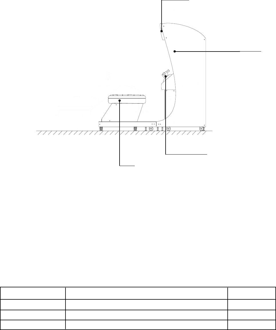
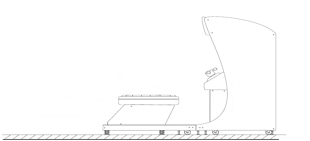
4. NAME OF PARTS
TABLE 4 Dimensions and Weights
Marquee
Monitor
Seat
Control Panel
Items Width X Depth X Height Weight
Cabinet 30.25in (W) X 35.75in (D) X 77.5in (H) 450 lbs
Seat Section 30.25in (W) X40.75in (D) X 25.25in (H) 100 lbs
When assembled 30.25in (W) X 76.5in (D) X 77.5in (H) 550 lbs
8
www.seuservice.com
www.seuservice.com
9
SERVICE MANUAL NAOMI ENG
420-6455-01 (1)
INSTRUCTION MANUAL FOR THE
GAME BOARD
KEY MASTER
220-5576 (2)
For opening/closing the doors
KEY (2)
For the CASHBOX DOOR
The Keys are inside the Coin Chute Door at the time of shipment
from the factory.
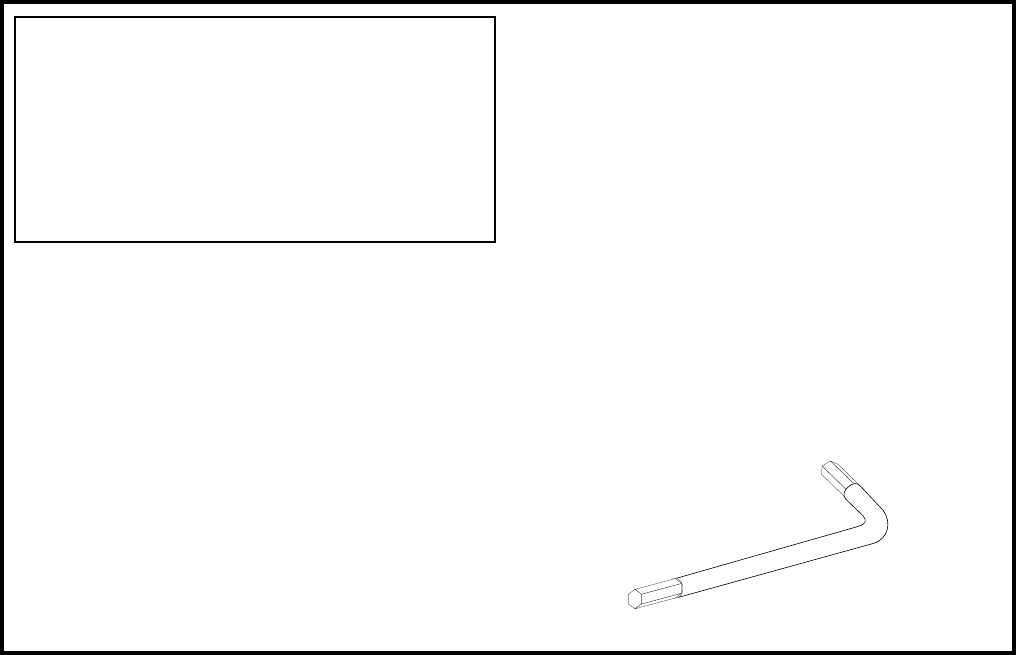
5. ACCESSORIES
When transporting the machine, make sure that the following parts are supplied.
TABLE 5 a ACCESSORIES
DESCRIPTION OWNERS MANUAL
Part No. (Qty.)
999-XXXX (1)
Note
Figures
If Part No. has no description, the Number has not been
registered or can not be registered. Such a part may not be
obtainable even if the customer desires to purchase it.
Therefore, ensure that the part is in safekeeping with you.
TAMPERPROOF
WRENCH
T-27 Torx 1/4-20 (1)
T-15 Torx 8/32 (1)
Tool

10
www.seuservice.com
www.seuservice.com
11
②
③
①
HOW TO USE THE CARTON BOX
When requesting for the replacement/repair of this product's Game Board (NAOMI
BOARD), follow the instructions below. Transporting the Game Board in an undesig-
nated status is unacceptable. An erroneous handling can cause parts damage.
• Put the Game Board in the Carton Box together with the Shield Case. Do not un-
necessarily disassemble nor remove parts.
• By paying careful attention to the following Figure and the direction shown by on-
Carton-Box printing, put the Shield Case in the Carton Box.
• When putting the Shield Case in the Carton Box, do not remove Leg Brackets.
• The projected portions of the packing material is intended for cushioning. There-
fore, do not bend the projected portions.
Bend the packing material in numerical order, and wrap the Shield Case with the packing material
and put it in the Carton Box as shown. Putting it upside down or packing otherwise in the manner not
shown can damage the Game Board and the parts.
FILTER BOARD
Projected portions of
the packing material.
Serial No. Display
Serial No. Display
"CHECK SIDE" Display
FIG. 5
STOP
IMPORTANT!
10
www.seuservice.com
www.seuservice.com
11
Perform assembly work by following the procedure herein stated. Failing to com-
ply with the instructions can cause electric shock hazard.
Perform assembling as per this manual. Since this is a complex machine, erroneous
assembling can cause an electric shock, machine damage and or not functioning as
per specied performance.
When assembling, be sure to use plural persons. Depending on the assembly work,
there are some cases in which working by one person alone can cause personal
injury or parts damage.
Ensure that connectors are accurately connected. Incomplete connections can cause
electric shock hazard.
Be careful so as not to damage wirings. Damaged wiring can cause electric shock
and short circuit hazards.
Do not carelessly push the PTV. Pushing the PTV carelessly can cause the PTV to
fall down.
This work should be performed by the Location's Maintenance Man or Serviceman.
Performing work by non-technical personnel can cause a severe accident such as
electric shock. Failing to comply with this instruction can cause a severe accident
such as electric shock to the player during operation.
Provide sufcient space so that assembling can be performed. Performing work in
places with narrow space or low ceiling may cause an accident and assembly work
to be difcult.
To perform work safely and avoid serious accident such as the cabinet's falling
down, do not perform work in places where step-like grade differences, a ditch, or
slope exist.
6. ASSEMBLING AND INSTALLATION
To perform work safely and securely, be sure to prepare a step which is in a secure and
stable condition. Performing work without using the step can cause violent falling
down accidents.
SECURING IN PLACE (ADJUSTER ADJUSTMENT)
POWER SUPPLY, AND EARTH CONNECTION
TURNING POWER ON
ASSEMBLY CHECK
When carrying out the assembling and installation, follow the following 7-item sequence.
WARNING!
CAUTION!
1
2
3
4
12
www.seuservice.com
www.seuservice.com
13
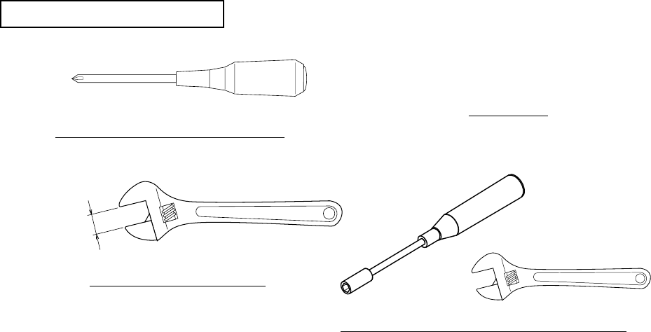
Phillips type screwdriver (for M4, M5 screw)
KEY MASTER
WRENCH (for M16 hexagon bolt)
Box nut screwdriver (for M4 hexagon nut) or WRENCH
Tools required for the work

12
www.seuservice.com
www.seuservice.com
13
SECURING IN PLACE (ADJUSTER ADJUSTMENT)
Transport the product to the
installation position. Be sure to
provide adequate space allowing
the player to get on and off.
Have all of the Adjusters make
contact with the oor. Adjust
the Adjuster's height by using
a wrench so that the machine
position is kept level.
After making adjustment, fasten
the Adjuster Nut upward and
secure the height of Adjuster
(FIG. 6. 3 b). FIG. 6. 3 a BOTTOM VIEW
FIG. 6. 3 b ADJUSTER
Make sure that all of the adjusters are in contact with the oor. If they are not, the
cabinet can move and cause an accident.
This product has 8 casters (4 for FRONT CABINET, 4 for REAR CABINET) and 8 Adjusters
(4 for FRONT CABINET, 4 for REAR CABINET). (FIG. 6. 3a) When the installation position is
determined, cause the adjusters to come into contact with the oor directly, make adjustments in a
manner so that the casters will be raised approximately 5mm from the oor and make sure that the
machine position is level.
ADJUSTER
Approx.5mm
ADJUSTER
CASTER
FASTEN UPWARD.
ADJUSTER
CASTER
FIG. 6. 3 c
Refer to this Fig. (Scale:1/100) for
the layout of the place of installation.
FIG. 6. 3 d
Be sure to provide space as shown between the Air
Vent and the wall surface.
15cm
10cm
WARNING!
1
1
2
3
Note: Actual unit will differ from image.
Note: Actual unit will differ from image.
14
www.seuservice.com
www.seuservice.com
15
Be sure to independently use the power supply socket outlet equipped with an Earth
Leakage Breaker. Using a power supply without an Earth Leakage Breaker can
cause a re when electric leakage occurs.
Ensure that the "accurately grounded indoor earth terminal" and the earth wire cable
are available (except in the case where a power cord plug with earth is used). This
product is equipped with the earth terminal. Connect the earth terminal and the in-
door earth terminal with the prepared cable. If the grounding work is not performed
appropriately, customers can be subjected to an electric shock, and the product's
functioning may not be stable.
Ensure that the power cord and earth wire are not exposed on the surface (passage,
etc.). If exposed, they can be caught and are susceptible to damage. If damaged,
the cord and wire can cause electric shock and short circuit accidents. Ensure that
the wiring position is not in the customer's passage way or the wiring has protective
covering.
After wiring power cord on the oor, be sure to protect the power cord. Exposed
power cord is susceptible to damage and causes an electric shock accident.
POWER SUPPLY, AND EARTH CONNECTION
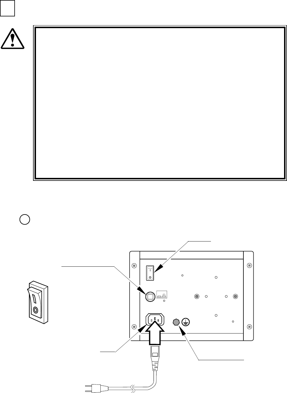
The AC Unit is mounted on the right side of the machine. The AC Unit has Main SW, Circuit Pro-
tector, Earth Terminal and the Inlet which connects the Power Cord.
Ensure that the Main SW is OFF.
FIG. 6. 5 a AC UNIT
INLET
CIRCUIT PROTECTOR
MAIN SW
EARTH TERMINAL
Connect with the
indoor earth terminal.
AC Cable (Power Cord)
Main SW off
WARNING!
2
1

14
www.seuservice.com
www.seuservice.com
15
Connect one end of the earth wire to the AC Unit earth
terminal, and the other end to the indoor earth ter-
minal. The AC Unit earth terminal has a Bolt and Nut
combination. Take off the Nut, pass the end of earth
wire through the Bolt, and fasten the Nut.
Note that the Earth Wire is incorporated in the Power
Cord for the Areas of AC 120V (USA) and AC 220 ~
240V, and therefore, this procedure is not necessary.
Connect the Earth Wire
to the Earth Terminal.
FIG. 6. 5 b Earth Wire Connection
Firmly insert the power plug into the
socket outlet.
Insert the opposite side of Power Cord
plug to the AC Unit's connector ("IN-
LET").
Perform wiring for the Power Cord
and Earth Wire. Install protective
covering for the Power Cord and
Earth Wire.
FIG. 6. 5 c Connecting Power Cord and Earth Wire
Wiring Cover
In case the Power Plug is apt to come out of place, secure the
Power Cord to the periphery of the AC Unit with the Cord Clamp
(an accessory).
HOW TO USE THE CORD CLAMP
2
3
4
5

16
www.seuservice.com
www.seuservice.com
17
TURNING POWER ON
Turn the AC Unit Main SW ON to turn on the machine's power supply. At the same time the power is
turned on for the power supply, the machine starts the initialization setting and displays the screen on
which the setting is being made. Do not touch the Ride until the initialization setting movements are
automatically nished.
After nishing the initialization setting movements, the ADVERTISE mode returns. During the
setting movements, if any irregularity, malfunctioning, etc. of the moving mechanism are found,
ERROR display is shown on the lower part of the ADVERTISE mode screen. In this case, the
machine will not operate satisfactorily. Please contact the Distributor, etc. where this product was
purchased from.
In the case where several machines are connected, network check is performed after initialization
settings are nished, and the screen displays to the effect that the check is being conducted. After
checking, the ADVERTISE mode returns. Normally the network checking takes 1 ~ 3 minutes. If
there is any irregularity in the communication connection, check screen display will continue.
3
16
www.seuservice.com
www.seuservice.com
17
ASSEMBLY CHECK
In the TEST MODE, ascertain that the assembly has been made correctly and IC BD is satisfactory
(refer to Section 9).
In the test mode, perform the following test:
( ) MEMORY TEST
Selecting the RAM TEST in the test mode
menu causes the on-board memory to be tested
automatically. The game board is satisfactory if the
display beside each IC No. shows GOOD.
( ) C.R.T. TEST
In the test mode menu, selecting C.R.T. TEST allows the screen
(on which the projector is tested) to be displayed. Although the
projector adjustments have been made at the time of shipment
from the factory, color deviation, etc., may occur due to the effect
caused by geomagnetism, the location building's steel frames and
other game machines in the periphery. By watching the test mode
screen, make judgment as to whether an adjustment is needed. If
it is necessary, adjust the projector by referring to Section 14.
RAM TEST
IC29 GOOD
IC35 GOOD
IC09 GOOD IC10 GOOD
IC11 GOOD IC12 GOOD
IC16 GOOD IC18 GOOD
IC20 GOOD IC22 GOOD
IC17 GOOD IC19 GOOD
IC21 GOOD IC23 GOOD
PRESS TEST BUTTON TO EXIT
C.R.T. TEST 1/2
1 32
RED
GREEN
BLUE
WHITE
PRESS TEST BUTTON TO CONTINUE
C.R.T. TEST 2/2
PRESS TEST BUTTON TO EXIT
1
2
4
18
www.seuservice.com
www.seuservice.com
19
( 4 ) INPUT TEST
Selecting the INPUT TEST on the test mode menu
screen causes the screen (on which each switch and
V. R. are tested) to be displayed. Press each switch.
If the display beside each switch indicates "ON," the
switch and wiring connections are satisfactory.
Check the display of each V.R. value. If the V. R. is
malfunctioning, refer to Sections 11 & 12.
( 5 ) OUTPUT TEST
In the output test mode, carry out lamp test to
ascertain that each lamp lights up satisfactorily.
( 3 ) SOUND TEST
In the test mode, selecting SOUND TEST causes
the screen (on which sound related BD and wiring
connections are tested) to be displayed.
Be sure to check if the sound is satisfactorily
emitted from each speaker and the sound volume is
appropriate.
Perform the above inspections also at the time of monthly inspection.
SOUND TEST
RIGHT SPEAKER OFF
LEFT SPEAKER OFF
EXIT
SELECT WITH SERVICE BUTTON
AND
PRESS TEST BUTTON
INPUT TEST
HANDLE BAR 0H
ROLL 0H
THROTTLE LEVER FFH
PITCH 0H
START OFF
VIEW OFF
SAFETY SENSOR OFF
SERVICE OFF
TEST OFF
PRESS TEST AND SERVICE BUTTON TO EXIT
OUTPUT TEST
> START LAMP OFF
VIEW LAMP OFF
EXIT
SELECT WITH SERVICE BUTTON
AND PRESS TEST BUTTON
18
www.seuservice.com
www.seuservice.com
19
7. PRECAUTIONS TO BE HEEDED WHEN MOVING THE MACHINE
When moving the machine, be sure to pull out the plug from the power supply.
Moving the machine with the plug as is inserted can cause the power cord to be
damaged, resulting in a re and or electric shock.
When moving the machine on the oor, retract the Adjusters and ensure that Cast-
ers make contact with the oor. During transportation, pay careful attention so
that Casters do not tread power cords and earth wires. Damaging the power cords
can cause an electric shock and or short circuit.
In places where step-like grade differences exist, be sure to separate the Base, and
the Cabinet. Inclining the Base can cause the Cabinet to fall off from the Base and
result in injury.
When lifting the cabinet, be sure to hold the catch portions or bottom part. Lifting
the cabinet by holding other portions can damage parts and installation portions
due to the empty weight of the cabinet, and cause personal injury.
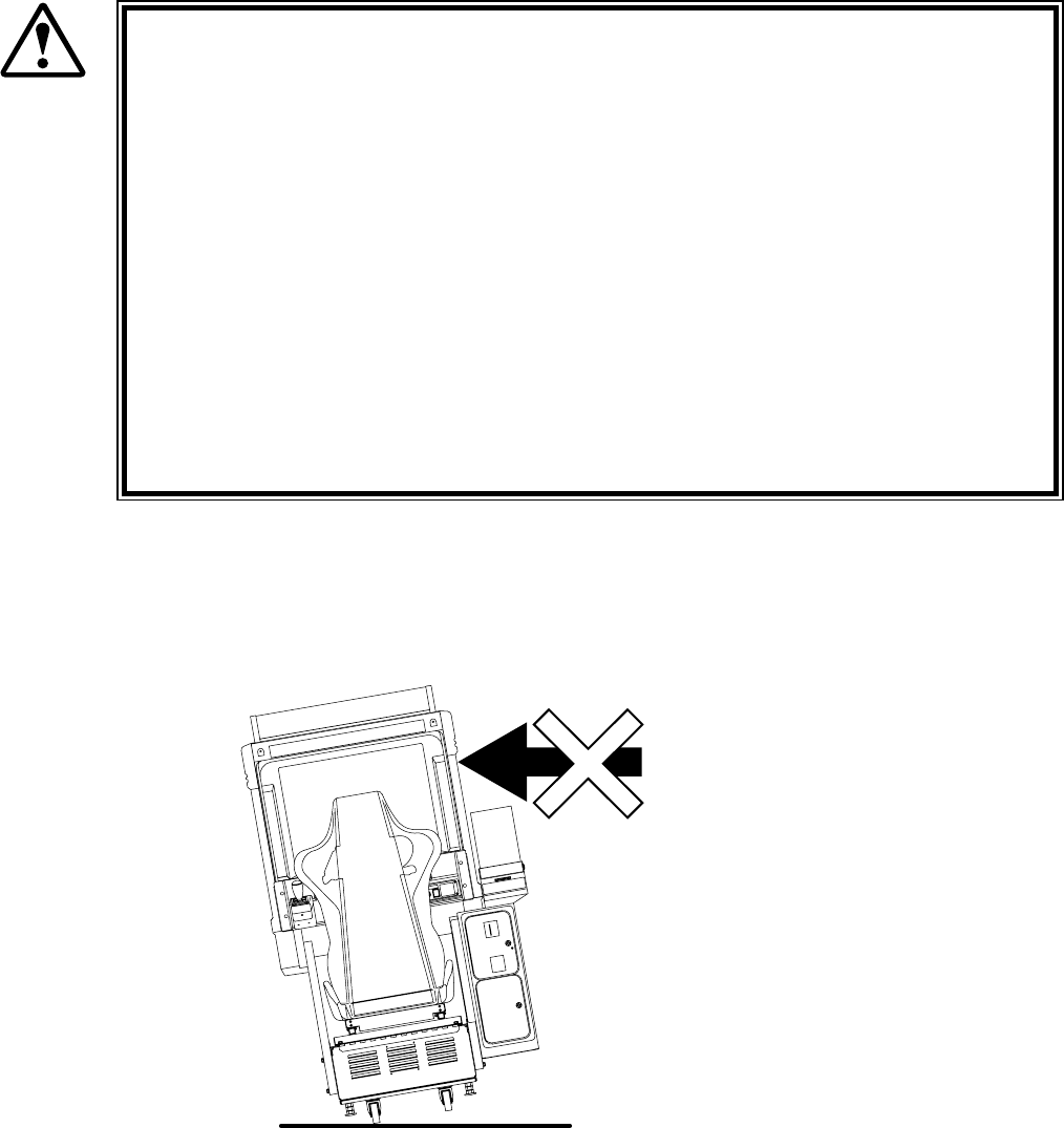
When moving the unit, do not push it from the rear side. Push it from sideways.
WARNING!
FIG. 8 a
Do not push the
cabinet from the
left/right direction.
* Note: Image differs from actual Unit.
20
www.seuservice.com
www.seuservice.com
21
FIG. 7 b
When transporting the product in places with steps
or step-like differences in grade, disassemble into
each unit before transporting.

20
www.seuservice.com
www.seuservice.com
21
8. CONTENTS OF GAME
The following explanations apply to the case the product is functioning satisfactory. Should there be
any moves different from the following contents, some sort of faults may have occurred. Immediately
look into the cause of the fault and eliminate the cause therefore to ensure satisfactory operation.
While the power is connected to the system, in an advertising mode, the system opens an operation
explanation screen or a ranking data screen. The view button ashes when the screen explains how to
operate the view button.
Located on the left and right sides above the monitor, the speakers output audio information. You may
set the ADVERTISE SOUND item to OFF on the GAME ASSIGNMENTS screen so that this audio
output function is disabled in an advertising mode.
The start button ashes when the screen displays the PRESS START BUTTON message. This PRESS
START BUTTON message appears in two cases; when the credit reaches a game-startable level in an
advertising mode and shortly after opening the operation explanation screen.
System Behavior in Advertising (Plying-for-Hire) Mode
FIG. 8 a External View of the Cabinet
Fluorescent lamps are lit.
Image output on the monitor.
Emits sounds.
Throttle Lever
Start Button
Ride
View Button (Change the viewpoint)
Handlebars
Coin Inlet
22
www.seuservice.com
www.seuservice.com
23
It provides several marine scenes where a cruising course appearance varies from play to play.
The WaveRunner GP game features:
• Effects of Stern Wave
A stern wave is the wave produced on the wake of a boat. If your boat runs on the stern waves
produced by another boat, it may jump unexpectedly, reduce its speed, or meet any other
navigating difculty. You must prevent your boat from running on the stern waves and navigate it
with attention to where and how other boats are moving.
• Water-Level-Depending Jumps
A large jump (or a group of small jumps) may appear on the course when a water level is lower (or
higher). The jump that was submerged on your rst round cruise may be above the water on your
second round cruise. Therefore, you must navigate your boat differently and/or change a cruising
path, from cruise to cruise, so that you can use an approaching jump.
• Insert the coin(s).
• Make sure that the screen shows the PRESS START BUTTON message and that the start button
ashes, and then climb onto the seat.
• Press the start button, and make sure that the operation explanation screen appears. (See the note 1
below.)
• Wait until the time is counted down to 0 (zero) on the operation explanation screen or alternately
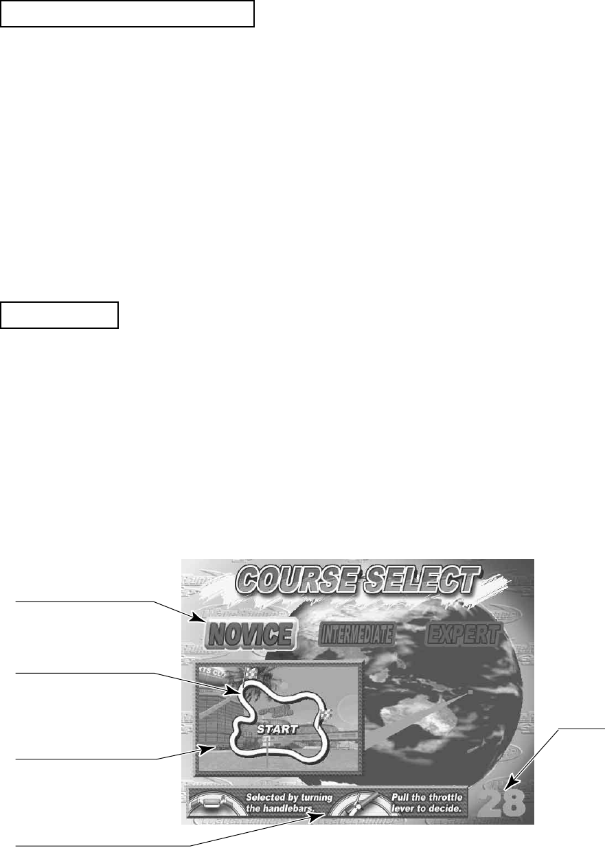
press the start button to exit the screen. In either case the COURSE SELECT screen appears.
FIG. 8 b
Highlights a selected
course.
Illustrates a course
layout.
Shows an image of the
selected course.
Indicates how to operate
the handlebars and the
throttle lever.
Indicates a limit
time for a course
selection.
Features of the WaveRunner GP
How to Play
22
www.seuservice.com
www.seuservice.com
23
• Wait until the time is counted down to 0 (zero) on the screen, and then the game starts. (See the
note 3 below.)
• Make sure that the boat starts to move at this moment.
• The screen shows some information; your ranking position among the players (on its upper right
part), a limit time (upper middle), your lap time, best lap time record, and best total time record
(upper left), a tachometer and a speed meter (bottom right), and a speed-down gauge (bottom left).
The speed-down gauge indicates a reduction of the cruising speed as a result of your boat running
on the stern waves. It is dimmed when your boat is not running on the stern waves.
FIG. 8 c
FIG. 8 d
Grip the throttle lever to
decide a course.
Turn the handlebars left/right
to choose the course.
View button
Start button
• The system provides three courses: NOVICE, INTERMEDIATE, and EXPERT. These are
displayed on the upper part of the screen. The selected course is highlighted. To migrate from one
course to another, turn the handlebars leftwards or rightwards. To decide a course, squeeze the
throttle lever. (See the note 2 below.)
Player's Lap Time
Best Lap Time Record
Best Total Time Record
Speed-Down Gauge
(It is dimmed when your boat
is not running on the stern
waves.)
Tachometer and
Speed Meter
Player's Ranking
Position
Limit Time

24
www.seuservice.com
www.seuservice.com
25
• When the game starts, the system starts counting down the limit time. If you successfully pass a
checkpoint on the course within the limit time, the bonus time is added to the remaining time. If not,
the game is over. (See the note 4 below.)
• For any course of NOVICE, INTERMEDIATE, or EXPERT. When you have successfully cruised
around it two times, you reach the goal and the game is over. (See the note 5 below.)
• To navigate the boat while playing the game, use the throttle lever and the handlebars, and tilt up the
boat by shifting your body. To increase a cruising speed, squeeze the throttle lever while to decrease
un-squeeze. To turn the boat leftwards and rightwards, turn the handlebars leftwards and rightwards
respectively. To quickly turn the boat, turn the handlebars and then tilt up the boat to a turning di-
rection of the handlebars. Note that just tilting up the boat without turning the handlebars does not
enable to turn the boat. Press the view button to toggle a viewpoint between a navigator's point and
a rearward point.
• When reaching the goal, you can register your name if your lap time is good. Your registered name
will be on a screen's ranking list in an advertising mode.
NOTES:
1) For an interactive communication play. Insert the one-play worth of coin(s) on the operation
explanation screen and press the start button to enter the race. The system opens the entry screen
where you wait until an opposition will enter the race by also inserting the one-play worth of
coin(s) and pressing the start button. The entry screen closes and the operation explanation screen
opens automatically, when a limit time is counted down to 0 (zero).
2) For an interactive communication play. When every player, after entering the race, has nished
selecting a course, the racing course is decided by majority. In case of a tie, the course with a lower
difculty level is chosen.
3) Alternately, you can press the start button to decide a course.
4) For an interactive communication play. The bonus time is added to the remaining time when a
leading player passes a checkpoint. The place of a player is indicated as 'place/the number of
players' (e.g. 2/4 for a 4-player race, 1/2 for 2-player race). A player number, as 1P and 2P, is
shown above the head of a playing character on the screen.
5) You cannot change the number of rounding cruises.
• When your boat runs on the stern waves, the speed-down gauge is undimmed and its triangle
becomes lled with shade. If you keep your boat running on the stern waves, the triangle is shaded
more and more.
When the triangle is fully shaded, a warning message "Get out of the wake!" appears on the screen.
If you make your boat off the stern waves at this moment, the speed-down gauge is again dimmed.
If not, it is initialized to 0 (zero) and becomes lled with shade again.
Initially the gauge is dimmed. When the boat runs on the stern
waves, the gauge is undimmed
and becomes lled with shade.
When the gauge is fully
shaded, a warning message
appears.
FIG 8 e

24
www.seuservice.com
www.seuservice.com
25
Three cruising courses are provided as below. Note that they are different from each other not only in
the difculty level but also in the appearance and device.
• Novice Course
This course gives the image of a tropical island against a blue sky where the hot sun grills white
beaches. Generally, this novice course curves very gently.
There are three checkpoints including a starting point.
When your boat approaches a palm tree, the coconuts will fall down on your cruising path. Three
dolphins may appear on the way and accompany your boat.
The key part for reaching the goal is located at the end of the course that is sharply curved and
enclosed with the cliffs.
• Intermediate Course
This course gives the image of a thick rainforest with mysterious remains. Generally, this
intermediate course is a very narrow river with rather many curves.
There are four checkpoints including a starting point.
The highlight of this course is a jump from the 50-meter giant waterfall.
In the mangrove woodlands, tall mangroves block your boat. You must be careful not to let it hit
against them.
Big snakes and giant shes produce an atmosphere of rainforest.
The key parts for reaching the goal are the curves located short of the giant waterfall, in the
mangrove woodlands, and in the cave at the end of the course. You must navigate your boat with
careful attention to these curved spots.
• Expert Course
This course gives the image of a waterfront where the surrounding skyscrapers are blazing in the
evening darkness. This expert course features several combinations of a straight path and a sharp
curve.
There are four checkpoints including a starting point.
All the scenes (the likes of the Brooklyn Bridge, the Statue of Liberty, and the Broadway with loud
neon signs and large illumination bulletin boards) produce an atmosphere of big city.
The key part for reaching the goal is the sharp curves located immediately after the straight paths.
Outline of the Courses

26
www.seuservice.com
www.seuservice.com
27
When the 2 or more machines are linked for communication play, be careful to enter the
TEST mode. If one of the machines linked enters the TEST mode, all others display the
NETWORK CHECK screen.
By operating the switch unit, periodically perform the tests and data check. When installing the ma-
chine initially or collecting cash, or when the machine does not function correctly, perform checking
in accordance with the explanations given in this section.
The following shows tests and modes that should be utilized as applicable.
NAOMI GAME BOARD is used for the product. The system of this game board allows another
game to be played by replacing the ROM Board Case mounted on the NAOMI CASE. As such, the
Test Mode of this system consists of the System Test Mode for the system to execute SELF-TEST,
COIN ASSIGNMENTS, etc. used in common for the machines employing the NAOMI BOARD, and
the Game Test Mode for the specic product to execute Input/Output test for the operation equipment,
difculty setting, etc.
9. EXPLANATION OF TEST AND DATA DISPLAY
STOP
IMPORTANT!
26
www.seuservice.com
www.seuservice.com
27
SERVICE MANUAL
9-3d
9-3b
9-3c
SERVICE MANUAL
SERVICE MANUAL
SERVICE MANUAL
9-3d, e
9-3b
9-3c
SERVICE MANUAL
9-3e
11,12
SERVICE MANUAL
14
SERVICE MANUAL
SERVICE MANUAL
SERVICE MANUAL
9-3h
TABLE 10 EXPLANATION OF TEST MODE
INSTALLATION
OF MACHINE
MEMORY
PERIODIC
SERVICING
CONTROL
SYSTEM
MONITOR
IC BOARD
DATA CHECK
When the machine is installed, perform the following:
1. Check to see that each setting is as per standard setting made at
the time of shipment.
2. In the INPUT TEST mode, check such input devices as each
SW, V.R., etc.
3. In the OUTPUT TEST mode, check such output devices as
lamps, motors, etc.
4. In the self-test mode, check ICs on the IC Board.
Choose the board test item in the MENU mode to allow the self-
test to be performed. In this test, PROGRAM RAMs, ROMs, and
ICs on the IC Board are checked.
Periodically perform the following:
1. Self-Test
2. Ascertain each setting.
3. In the INPUT TEST mode, test the control device.
4. In the OUTPUT TEST mode, check such output devices as
lamps, motors, etc.
1. In the INPUT TEST mode, check such input devices as each
SW, V.R., etc.
2. Adjust or replace each SW and VR.
3. If the problem can not be solved yet, check the control's moves.
In the MONITOR ADJUSTMENT mode, check to see if the
MONITOR adjustment is appropriately made.
1. Self-Test
2. In the SOUND TEST mode, check the sound related ROMs.
Check such data as game play time and histogram to adjust the
difculty level, etc.
ITEMS DESCRIPTION REFERENCE
SECTIONS
28
www.seuservice.com
www.seuservice.com
29
Do not touch places other than those specied. Touching places not specied can cause
an electric shock or short circuit accident.
9 - 1 SWITCH UNIT AND COIN METER
Adjust to the optimum sound volume by considering the environmental
requirements of the installation location.
If the COIN METER and the game board are electrically disconnected, game play
is not possible.
SWITCH UNIT
Open the coin chute door, and the switch unit
shown will appear. The functioning of each SW
is as follows:
FIG. 9. 1 a SWITCH UNIT
TEST BUTTON : For the handling of the test button, refer to the following pages.
(TEST)
SERVICE BUTTON : Gives credits without registering on the coin meter.
(SERVICE)
SOUND VOLUME : Adjust the Speaker Volume.
(SOUND VOLUME)
Open the Cashbox Door with the exclusively used key
and the COIN METER will appear underneath the
Cashbox.
COIN METER
TEST BUTTON
SOUND VOLUME SERVICE BUTTON
COIN METER
FIG. 9. 1 b COIN METER
WARNING!
STOP
IMPORTANT!

28
www.seuservice.com
www.seuservice.com
29
In the SYSTEM TEST MODE, IC BD functioning can be checked, the monitor adjusted, and the coin
setting performed.
Refer to NAOMI SERIVCE MANUAL for the details. Note that the setting of the following items
need to be performed in accordance with the instruction given.
• CABINET TYPE: 1PLAYER(S)
• MONITOR TYPE: HORIZONTAL
• SERVICE TYPE: COMMON
• COIN CHUTE TYPE: COMMON
The SEQUENCE SETTING items of COIN ASSIGNMENTS are as follows.
• SEQUENCE SETTING
SEQUENCE 1: Number of credits required for starting the game.
SEQUENCE 2: Number of credits required for continuing the play.
SEQUENCE 3 ~ 8: NOT USED
9 - 2 SYSTEM TEST MODE
The contents of settings changed in the TEST mode are stored when the test mode
is nished from EXIT in the menu mode. If the power is turned off before the
TEST mode is nished, the contents of setting change become ineffective.
Executing "BACKUP DATA CLEAR" in the SYSTEM TEST MODE does not
clear the BOOKKEEPING data in the GAME TEST mode.
Entering the TEST mode clears fractional number of coins less than one credit and
BONUS ADDER data.
Perform setting as per specied in this manual for operation. If setting not speci-
ed is performed for operation, proper function of this product may not be ob-
tained.
STOP
IMPORTANT!
30
www.seuservice.com
www.seuservice.com
31
The new settings will not take effect until the Game Test Mode is exited. When you
make change to the settings, exit the Game Test Mode by proper operation.
You must not attempt to demonstrate this game (for the selling purpose) with any
other settings other than those specied in this document. Use of such settings may
cause malfunctions or bad operation on the machine.
By selecting GAME TEST MODE from the System Test Menu Screen, the Game Test Mode Menu
Screen is displayed as follows.
9 - 3 GAME TEST MODE
System Test Menu Screen
As soon as it enters the Game Test mode, the Ride starts moving. Before entering the
Game Test Mode, be sure to keep away a person(s) from the Ride. Since the Ride
moves momentarily, it may cause accidents.
• Press the TEST Button to cause the following Test Menu to be displayed on the monitor.
• Press the SERVICE Button until the pointer ">" is moved to the desired item to make a selection.
• Bring the pointer ">" to the desired item and press the TEST Button to enter the selected item's
test.
• In the Test mode, the Start button instead of Test button and the View button instead of Service
button can be used. These, however, can not be used in the INPUT TEST.
• After the test is complete, move ">" to "EXIT" and press the TEST Button to return to the System
Test Menu Screen.
SYSTEM MENU
RAM TEST
JVS TEST
SOUND TEST
C.R.T. TEST
SYSTEM ASSIGNMENTS
COIN ASSIGNMENTS
BOOKKEEPING
BACKUP DATA CLEAR
CLOCK SETTING
ROM BOARD TEST
GAME TEST MODE
[*****************]
-> EXIT
SELECT WITH SERVICE BUTTON
AND
PRESS TEST BUTTON
GAME TEST MENU
INPUT TEST
OUTPUT TEST
GAME ASSIGNMENTS
VOLUME SETTING
VALVE TEST
WIRING TEST
BOOKKEEPING
BACKUP DATA CLEAR
> EXIT
SELECT WITH SERVICE BUTTON
AND PRESS TEST BUTTON
GAME TEST MENU
FIG. 9. 3 a Game Test Menu Screen
STOP
IMPORTANT!
CAUTION!

30
www.seuservice.com
www.seuservice.com
31
INPUT TEST
HANDLE BAR 0H
ROLL 0H
THROTTLE LEVER FFH
PITCH 0H
START OFF
VIEW OFF
SAFETY SENSOR OFF
SERVICE OFF
TEST OFF
PRESS TEST AND SERVICE BUTTON TO EXIT
INPUT TEST
When INPUT TEST is selected, the following screen appears on the monitor. The screen allows the
status of each SW and the value of each V.R. of the cabinet to be viewed.
On this screen, periodically check the status of each switch & V.R.
• By pressing each switch, if the display on the
right-hand side of the name of each switch
changes to ON from OFF, the SW and the wiring
connections are satisfactory.
• Simultaneously pressing the Service button and
the Test button returns the Game Test Menu
screen.
The standard values for adjusting each V. R. are as follows:
In this product, the item of VOLUME SETTING allows V. R. values except for PITCH to be set.
THROTTLE LEVER:e 0 H + 9 (lever released)
Without a moving base you will not be able to do ROLL, PITCH, or SAFETY SENSOR.
32
www.seuservice.com
www.seuservice.com
33
OUTPUT TEST
The OUTPUT TEST allows the function of each lamp to be checked.
OUTPUT TEST
> START LAMP OFF
VIEW LAMP OFF
EXIT
SELECT WITH SERVICE BUTTON
AND PRESS TEST BUTTON
FIG. 9. 3 c OUTPUT TEST Screen
Press the SERVICE Button to bring the arrow to the lamp item to be tested.
Pressing the TEST Button causes "ON" to be displayed and the corresponding lamp lights up.
Pressing the TEST Button again causes "OFF" to be displayed and the lamp goes off.
Bring the arrow to EXIT and press the TEST Button to return to the Game Test Menu screen.
TEST PROCEDURE
3
2
1

32
www.seuservice.com
www.seuservice.com
33
GAME ASSIGNMENTS
Selecting the GAME ASSIGNMENTS in the menu mode causes the present game setting to be
displayed and also the game setting changes can be made. Each item displays the following content.
If the COMMUNICATION MODE is set to NO LINK, the items HANDICAP and CABINET ID will
not appear.
GAME DIFFICULTY: The game difculty can be differentiated by varying Time
at the time of starting the race and Time at the time of passing
the checkpoint. Choose one from among 3 categories, i.e.,
EASY, NORMAL and HARD.
COMMUNICATION MODE: Set up whether the communication (interactive) play is
enabled. There are 3 categories, i.e. MASTER (for one
machine/player only), SLAVE (for communication
play), and NO LINK (not for communication play).
HANDICAP: In the communication vs. play, this sets whether correction should
be made so that player boat in the second or lower positions
increase the speed. Correction is used with ON and use of
correction is cancelled with OFF.
CABINET ID: When linked for communication play, allocate the numbers
sequentially in order starting from the leftmost end.
For Communication play, refer to Section 20 "COMMUNICATION PLAY".
FIG. 9. 3 d GAME ASSIGNMENTS Screen
Press the SERVICE Button to bring the arrow (>) to the desired setting change item.
Press the TEST Button to choose the desired setting item.
Bring the arrow to EXIT and press the TEST Button to return to the Game Test Menu screen.
SETTING CHANGE PROCEDURE
GAME ASSIGNMENTS
GAME DIFFICULTY NORMAL
COMMUNICATION MODE NO LINK
HANDICAP ON
CABINET ID 1
> EXIT
SELECT WITH SERVICE BUTTON
AND PRESS TEST BUTTON
3
2
1
34
www.seuservice.com
www.seuservice.com
35
VOLUME SETTING
When V. R. adjustment or replacement has been made, be sure to perform the setting in
that particular V. R. value setting item.
In this setting item, each V. R. value of the Handlebars, Roll, and Throttle can be set.
FIG. 9. 3 e a VOLUME SETTING Screen
VOLUME SETTING
> HANDLE BAR
ROLL
THROTTLE LEVER
EXIT
SELECT WITH SERVICE BUTTON
AND PRESS TEST BUTTON
STOP
IMPORTANT!
34
www.seuservice.com
www.seuservice.com
35
(1) HANDLE BAR VOLUME SETTING
HANDLE BAR VOLUME SETTING
MAX 00 (FF)
MIN 00 (01)
NEUTRAL 00 (80)
> EXIT WITHOUT SAVE
EXIT WITH SAVE
SELECT WITH SERVICE BUTTON
AND PRESS TEST BUTTON
FIG. 9. 3 e b HANDLE BAR VOLUME SETTING Screen
In the V. R. setting menu screen, press the SERVICE Button to bring the arrow to HANDLE BAR.
Press the TEST Button to cause the HANDLE BAR VOLUME setting screen to appear.
Turn the Handlebars fully to the left/right and then release.
Press the SERVICE Button to bring the arrow to EXIT WITH SAVE.
Press the TEST Button to have the Volume Setting Menu screen return to the screen.
When setting other Volume values also, select the applicable select item.
Press the SERVICE Button to move the arrow to EXIT and press the TEST Button to return to the
Game Test Menu screen.
SETTING PROCEDURE
5
6
7
4
3
2
1
36
www.seuservice.com
www.seuservice.com
37
(2) ROLL VOLUME SETTING
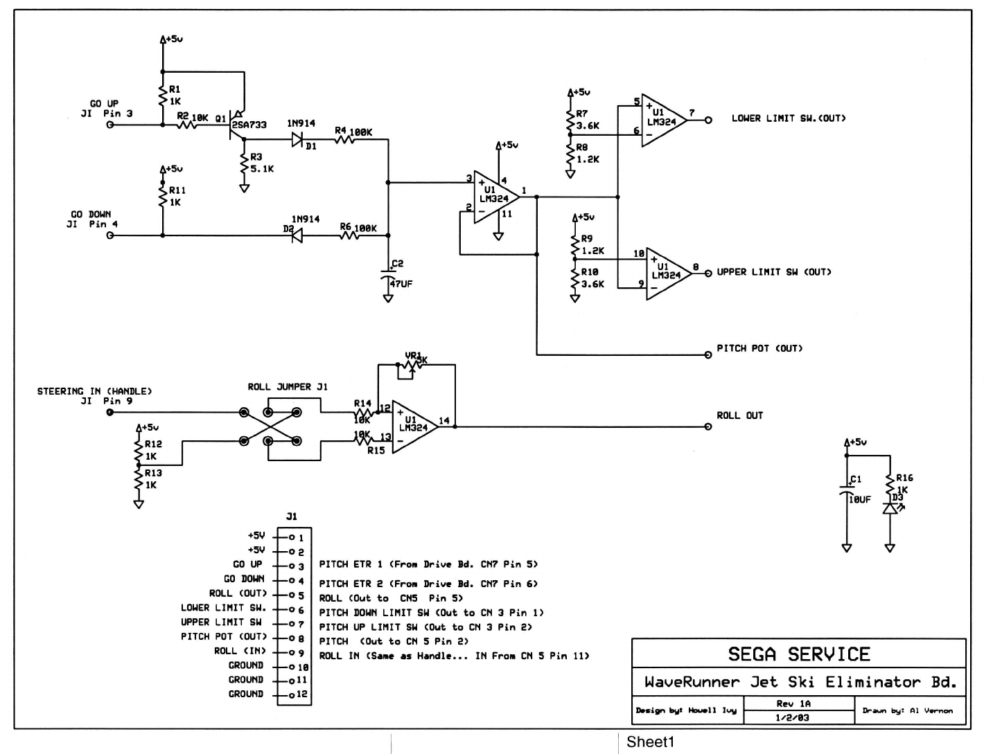
Being that this unit has no base. you will not be able to set the Roll Volume Setting, Pitch Valve & ETR
Check, Valve Test, or Roll Valve & ETR Check.
(1) PITCH VALVE & ETR CHECK
VALVE TEST
(2) ROLL VALVE & ETR CHECK

36
www.seuservice.com
www.seuservice.com
37
(3) THROTTLE LEVER VOLUME SETTING
THROTTLE LEVER VOLUME SETTING
MAX FF (3B)
MIN FF (00)
> EXIT WITHOUT SAVE
EXIT WITH SAVE
SELECT WITH SERVICE BUTTON
AND PRESS TEST BUTTON
FIG. 9. 3 e d THROTTLE LEVER VOLUME SETTING Screen
In the Volume Setting Menu, press the SERVICE Button and bring the arrow to THROTTLE
LEVER.
Press the TEST Button to have the THROTTLE VOLUME SETTING screen appear.
Fully grip the Throttle Lever and then release.
By pressing the SERVICE Button, bring the arrow to EXIT WITH SAVE.
Press the TEST Button to have the Volume Setting Menu return on the screen.
When setting other Volume values also, choose the applicable setting item.
Press the SERVICE Button to move the arrow to EXIT and press the TEST Button to return to the
Game Test Menu screen.
SETTING PROCEDURE
5
6
7
4
3
2
1

38
www.seuservice.com
www.seuservice.com
39
WIRING TEST
Selecting WIRING TEST allows the communication between GAME BD and DRIVE BD to be
checked automatically. If the communication is satisfactorily conducted, "OK" is displayed and if any
irregularity is found, "ERROR" will be displayed.
• After nishing the test, if the above Figure is displayed, it is satisfactory.
• After nishing the test, press the TEST Button to return to the Game Test Menu screen.
FIG. 9. 3 g WIRING TEST Screen
WIRING TEST
ok : ( f 0 ——> 1 1 1 1 1 1 1 0 )
ok : ( f 1 ——> 1 1 1 1 1 1 0 1 )
ok : ( f 2 ——> 1 1 1 1 1 0 1 1 )
ok : ( f 3 ——> 1 1 1 1 0 1 1 1 )
ok : ( f 4 ——> 1 1 1 0 1 1 1 1 )
ok : ( f 5 ——> 1 1 0 1 1 1 1 1 )
ok : ( f 6 ——> 1 0 1 1 1 1 1 1 )
ok : ( f 7 ——> 0 1 1 1 1 1 1 1 )
ok : ( f 8 ——> 1 0 1 1 1 1 1 1 )
ok : ( f 9 ——> 1 1 0 1 1 1 1 1 )
ok : ( f a ——> 1 1 1 0 1 1 1 1 )
ok : ( f b ——> 1 1 1 1 0 1 1 1 )
ok : ( f c ——> 1 1 1 1 1 0 1 1 )
ok : ( f d ——> 1 1 1 1 1 1 0 1 )
ok : ( f e ——> 1 1 1 1 1 1 1 0 )
ok : ( f f ——> 1 1 1 1 1 1 1 1 )
ok : ( 0 f ——> 0 1 1 1 1 1 1 1 )
ok : ( 1 f ——> 1 0 1 1 1 1 1 1 )
ok : ( 2 f ——> 1 1 0 1 1 1 1 1 )
ok : ( 3 f ——> 1 1 1 0 1 1 1 1 )
ok : ( 4 f ——> 1 1 1 1 0 1 1 1 )
ok : ( 5 f ——> 1 1 1 1 1 0 1 1 )
ok : ( 6 f ——> 1 1 1 1 1 1 0 1 )
ok : ( 7 f ——> 1 1 1 1 1 1 1 0 )
ok : ( 8 f ——> 1 1 1 1 1 1 0 1 )
ok : ( 9 f ——> 1 1 1 1 1 0 1 1 )
ok : ( a f ——> 1 1 1 1 0 1 1 1 )
ok : ( b f ——> 1 1 1 0 1 1 1 1 )
ok : ( c f ——> 1 1 0 1 1 1 1 1 )
ok : ( d f ——> 1 0 1 1 1 1 1 1 )
ok : ( e f ——> 0 1 1 1 1 1 1 1 )
ok : ( f f ——> 1 1 1 1 1 1 1 1 )
PRESS TEST BUTTON TO EXIT

38
www.seuservice.com
www.seuservice.com
39
BOOKKEEPING
Selecting the BOOKKEEPING in the menu mode displays the bookkeeping data up to the present on
the following 12 screens. Press the TEST Button again to proceed to the next page. When you press
the TEST Button during the display of this mode, you return to the Game Test Menu.
NUMBER OF GAMES: Number of games played.
TOTAL TIME(TOTAL): Total energized time.
PLAY TIME(1P): Total playtime of one player game only.
PLAY TIME(VS): Total playtime of communication game play.
FIG. 9. 3 h a BOOKKEEPING (1/12) Screen
BOOKKEEPING 1/12
NUMBER OF GAMES 94
PLAY TIME(TOTAL) 0D 2H 11M 11S
PLAY TIME(1P) 0D 2H 4M 2S
PLAY TIME(VS) 0D 0H 7M 9S
AVERAGE PLAY TIME 0H 1M 23S
LONGEST PLAY TIME 0H 3M 47S
SHORTEST PLAY TIME 0H 0M 2S
PRESS TEST BUTTON TO CONTINUE

40
www.seuservice.com
www.seuservice.com
41
(1) PLAY TIME HISTOGRAM
The time that players have been timeout is displayed in graph. It's a total of 2 screens.
FIG. 9. 3 h b BOOKKEEPING (2 - 3/12) Screen
BOOKKEEPING 2/12
PLAY TIME HISTOGRAM 1/2
0M00S ~ 0M09S 22
0M10S ~ 0M19S 3
0M20S ~ 0M29S 1
0M30S ~ 0M39S 0
0M40S ~ 0M49S 2
0M50S ~ 0M59S 1
1M00S ~ 1M09S 5
1M10S ~ 1M19S 27
1M20S ~ 1M29S 1
1M30S ~ 1M39S 2
1M40S ~ 1M49S 3
1M50S ~ 1M59S 2
2M00S ~ 2M09S 2
2M10S ~ 2M19S 2
2M20S ~ 2M29S 3
2M30S ~ 2M39S 2
2M40S ~ 2M49S 2
2M50S ~ 2M59S 0
PRESS TEST BUTTON TO CONTINUE
BOOKKEEPING 3/12
PLAY TIME HISTOGRAM 2/2
3M00S ~ 3M09S 4
3M10S ~ 3M19S 3
3M20S ~ 3M29S 3
3M30S ~ 3M39S 3
3M40S ~ 3M49S 1
3M50S ~ 3M59S 0
4M00S ~ 4M09S 0
4M10S ~ 4M19S 0
4M20S ~ 4M29S 0
4M30S ~ 4M39S 0
4M40S ~ 4M49S 0
4M50S ~ 4M59S 0
OVER 5M00S 0
PRESS TEST BUTTON TO CONTINUE

40
www.seuservice.com
www.seuservice.com
41
(2) CLEAR TIME HISTOGRAM
The clear time of the player, which has made a goal, is displayed in graph. Screens are two screens in
NOVICE, INTERMEDIATE and EXPERT, respectively. So it's a total of 6 screens.
FIG. 9. 3 h c BOOKKEEPING (4 - 9/12) Screen
BOOKKEEPING 4/12
CLEAR TIME HISTOGRAM 1/2
NOVICE
0M00S ~ 0M09S 0
0M10S ~ 0M19S 0
0M20S ~ 0M29S 0
0M30S ~ 0M39S 0
0M40S ~ 0M49S 0
0M50S ~ 0M59S 0
1M00S ~ 1M09S 0
1M10S ~ 1M19S 0
1M20S ~ 1M29S 0
1M30S ~ 1M39S 0
1M40S ~ 1M49S 0
1M50S ~ 1M59S 0
2M00S ~ 2M09S 0
2M10S ~ 2M19S 0
2M20S ~ 2M29S 0
2M30S ~ 2M39S 0
2M40S ~ 2M49S 0
2M50S ~ 2M59S 0
PRESS TEST BUTTON TO CONTINUE
BOOKKEEPING 5/12
CLEAR TIME HISTOGRAM 2/2
NOVICE
3M00S ~ 3M09S 0
3M10S ~ 3M19S 0
3M20S ~ 3M29S 0
3M30S ~ 3M39S 2
3M40S ~ 3M49S 1
3M50S ~ 3M59S 0
4M00S ~ 4M09S 0
4M10S ~ 4M19S 0
4M20S ~ 4M29S 0
4M30S ~ 4M39S 0
4M40S ~ 4M49S 0
4M50S ~ 4M59S 0
OVER 5M00S 0
PRESS TEST BUTTON TO CONTINUE
BOOKKEEPING 6/12
CLEAR TIME HISTOGRAM 1/2
INTERMEDIATE
0M00S ~ 0M09S 0
0M10S ~ 0M19S 0
0M20S ~ 0M29S 0
0M30S ~ 0M39S 0
0M40S ~ 0M49S 0
0M50S ~ 0M59S 0
1M00S ~ 1M09S 0
1M10S ~ 1M19S 0
1M20S ~ 1M29S 0
1M30S ~ 1M39S 0
1M40S ~ 1M49S 0
1M50S ~ 1M59S 0
2M00S ~ 2M09S 0
2M10S ~ 2M19S 0
2M20S ~ 2M29S 0
2M30S ~ 2M39S 0
2M40S ~ 2M49S 0
2M50S ~ 2M59S 0
PRESS TEST BUTTON TO CONTINUE
BOOKKEEPING 7/12
CLEAR TIME HISTOGRAM 2/2
INTERMEDIATE
3M00S ~ 3M09S 0
3M10S ~ 3M19S 0
3M20S ~ 3M29S 0
3M30S ~ 3M39S 0
3M40S ~ 3M49S 0
3M50S ~ 3M59S 0
4M00S ~ 4M09S 0
4M10S ~ 4M19S 0
4M20S ~ 4M29S 0
4M30S ~ 4M39S 0
4M40S ~ 4M49S 0
4M50S ~ 4M59S 0
OVER 5M00S 0
PRESS TEST BUTTON TO CONTINUE
BOOKKEEPING 8/12
CLEAR TIME HISTOGRAM 1/2
EXPERT
0M00S ~ 0M09S 0
0M10S ~ 0M19S 0
0M20S ~ 0M29S 0
0M30S ~ 0M39S 0
0M40S ~ 0M49S 0
0M50S ~ 0M59S 0
1M00S ~ 1M09S 0
1M10S ~ 1M19S 0
1M20S ~ 1M29S 0
1M30S ~ 1M39S 0
1M40S ~ 1M49S 0
1M50S ~ 1M59S 0
2M00S ~ 2M09S 0
2M10S ~ 2M19S 0
2M20S ~ 2M29S 0
2M30S ~ 2M39S 0
2M40S ~ 2M49S 0
2M50S ~ 2M59S 0
PRESS TEST BUTTON TO CONTINUE
BOOKKEEPING 9/12
CLEAR TIME HISTOGRAM 2/2
EXPERT
3M00S ~ 3M09S 0
3M10S ~ 3M19S 0
3M20S ~ 3M29S 0
3M30S ~ 3M39S 0
3M40S ~ 3M49S 0
3M50S ~ 3M59S 0
4M00S ~ 4M09S 0
4M10S ~ 4M19S 0
4M20S ~ 4M29S 0
4M30S ~ 4M39S 0
4M40S ~ 4M49S 0
4M50S ~ 4M59S 0
OVER 5M00S 0
PRESS TEST BUTTON TO CONTINUE

42
www.seuservice.com
www.seuservice.com
43
(3) Detailed data of each course
Allows for checking the detailed data of each course; NOVICE, INTERMEDIATE and EXPERT. It's
a total of 3 screens on each course 1 screen.
FIG. 9. 3 h d BOOKKEEPING (10 - 12/12) Screen
2nd line of the screen:
Indicates the course name and the total
playing time.
1st - 14th:
Indicates the ranking at the play end
time. (It's not whether the game was
cleared or not.)
CHECK 1-6 or 8:
Indicates the number of players, which
arrived at each check-point.
AVR:
Indicates the average time of each
checkpoint section.
BOOKKEEPING 10/12
NOVICE 68
1st 6 8th 1
2nd 0 9th 2
3rd 0 10th 0
4th 0 11th 0
5th 0 12th 1
6th 0 13th 0
7th 2 14th 56
CHECK1 17 AVR. 43S
CHECK2 15 AVR. 37S
CHECK3 11 AVR. 36S
CHECK4 8 AVR. 27S
CHECK5 4 AVR. 34S
CHECK6 2 AVR. 36S
PRESS TEST BUTTON TO CONTINUE
BOOKKEEPING 11/12
INTERMEDIATE 15
1st 0 8th 0
2nd 0 9th 1
3rd 0 10th 1
4th 0 11th 1
5th 0 12th 0
6th 0 13th 1
7th 1 14th 10
CHECK1 9 AVR. 34S
CHECK2 7 AVR. 27S
CHECK3 6 AVR. 27S
CHECK4 5 AVR. 26S
CHECK5 4 AVR. 20S
CHECK6 1 AVR. 27S
CHECK7 0 AVR. 0S
CHECK8 0 AVR. 0S
PRESS TEST BUTTON TO CONTINUE
BOOKKEEPING 12/12
EXPERT 8
1st 1 8th 1
2nd 0 9th 0
3rd 0 10th 0
4th 0 11th 1
5th 0 12th 0
6th 0 13th 0
7th 0 14th 5
CHECK1 5 AVR. 31S
CHECK2 5 AVR. 31S
CHECK3 4 AVR. 25S
CHECK4 4 AVR. 32S
CHECK5 3 AVR. 25S
CHECK6 1 AVR. 30S
CHECK7 0 AVR. 0S
CHECK8 0 AVR. 0S
PRESS TEST BUTTON TO EXIT

42
www.seuservice.com
www.seuservice.com
43
BACKUP DATA CLEAR
YES(CLEAR)
> NO (CANCEL)
SELECT WITH SERVICE BUTTON
AND PRESS TEST BUTTON
BACKUP DATA CLEAR
Clears the contents of BOOKKEEPING. When clearing the data, use the SERVICE Button to
bring the arrow to "YES (CLEAR)" and press the TEST Button. When clearing is nished, "COM-
PLETED" is displayed. Press the TEST Button again to return to the Game Test Menu screen. Bring
the arrow to "NO (CANCEL)" and press the TEST Button to have the Game Test Menu screen return
on the screen without clearing the data. Note that this operation does not affect the contents of the
game setting.
FIG. 9. 3 h c BACKUP DATA CLEAR Screen
44
www.seuservice.com
www.seuservice.com
45
FIG. 13 b
CRADLE
10. COIN SELECTOR
Turn the power for the machine OFF. Open the
coin chute door.
Remove the coin selector from the coin chute door.
Open the gate and dust off by using a soft brush
(made of wool, etc.).
Remove and clean smears by using a soft cloth
dipped in water or diluted chemical detergent and
then squeezed dry.
Remove the CRADLE.
When removing the retaining ring (E ring), be very
careful so as not to bend the rotary shaft.
Remove stain from the rotary shaft and shaft
receiving portions by wiping off with a soft cloth,
etc.
After wiping off as per above, further apply
a dry cloth, etc. to cause the coin selector to dry
completely.
CLEANING THE COIN SELECTOR
COIN INSERTION TEST
Once every month, when performing the
Coin SW Test, simultaneously check the
following:
Remove and clean smears by using a soft
cloth dipped in water or diluted chemical
detergent and then squeezed dry.
Never apply machine oil, etc. to the Coin
Selector.
After cleaning the Coin Selector, insert a
regular coin in the normal working status
and ensure that the Selector correctly func-
tions. FIG. 13 a
FIG. 13 c
GATE
Insert a coin
while keep-
ing the Reject
Button pressed
down and check
if it is rejected.
COIN METER
If the coin is not rejected when the REJECT button is pressed, open the coin chute door and open the
selector gate. After removing the jammed coin, put a normal coin in and check to see that the selector
correctly functions.
HANDLING THE COIN JAM
The coin selector should be cleaned once every 3 months.
When cleaning, follow the procedure below:
Does the Coin Meter count satisfactorily?
Does the coin drop into the Cashbox correctly?
Is the coin rejected when inserted while keeping the
Reject Button pressed down?
STOP
IMPORTANT!
1
2
3
4
7
6
5
5
44
www.seuservice.com
www.seuservice.com
45
COIN DOOR

46
www.seuservice.com
www.seuservice.com
47
Primary side and Secondary side
The monitor's circuit which is divided into the Primary side
and Secondary side, is electrically isolated. Do not touch
the primary side, or do not touch both the primary side
and the secondary side simultaneously. Failing to observe
the instruction can cause electric shock and this is very
dangerous. When making monitor adjustments, use a non-
conductive driver and make adjustment without touching
any part other than the Adjustment V. R. and knob. Also,
be sure not to cause a short-circuit to the Primary side and
Secondary side. If short-circuited, it can cause electric
shock or malfunctioning, which is very dangerous.
High-tension Voltage
Some of the parts inside monitor are subject to high-tension voltage in excess of 20,000 volts and
very dangerous. Therefore, do not touch the monitor interior. Should soldering & paper wastes,
etc. be mixed in the monitor interior, turn the power off so as not to cause malfunctioning or re
hazard.
Static Electricity
Touching the CRT surface sometimes causes you to slightly feel electricity. This is because the
CRT surfaces are subject to static and will not adversely affect the human body.
Installation and removal
Ensure that the Magnetizer Coil, FBT (Fly-Back Transformer), Anode Lead and Focus Lead are
not positioned close to the sheet metal work's sharp edges, etc. and avoid damaging the insulated
portions so as not to cause electric shock and malfunctioning. (For the name of parts, refer to the
above Figures).
SECONDARY SIDE
(Chassis, CRT)
ANODE LEAD
Approx. 29 kV MAIN BD
FBT Approx.
29 kV
ANODE CAP
FOCUS LEAD
(black)
Approx. 10 kV
SECONDARY SIDE
(Chassis, sheet metal work, CRT, etc.) Disconnect or unplug
NECK PCB
Approx.
10 kV
REAR PART
PRIMARY SIDE
Connecting the CRT and PCB
For combining the CRT and PCB, use the specied part No. to maintain the status of adjustments
made at the factory. The anode of the CRT itself will be accumulatively charged as time elapses,
generating high-tension voltage which is very dangerous. The monitor should be used with the
Chassis, CRT and PCB assembled. When repair, etc. is required at the time of malfunctioning, be
sure to send it in an "as is assembled" condition. If these are disassembled, what's charged to said
high tension voltage can be discharged, causing a very hazardous situation. Therefore, under no
circumstances should it be disassembled.
When performing such work as installing and removing the monitor, inserting and disconnecting
the external connectors to and from monitor interior and the monitor, be sure to disconnect the
power connector (plug) before starting the work. Proceeding the work without following this
instruction can cause electric shock or malfunctioning.
Using the monitor by converting it without obtaining a prior permission is not allowed. SEGA
shall not be liable for any malfunctioning and accident caused by said conversion.
11. MONITOR
Before handling the monitors, be sure to read the following explanations and comply with the
caution/warning instructions given below. Note that the caution/warning symbol marks and letters
are used in the instructions.
Indicates that handling the monitors by
disregarding this caution may cause a
potentially hazardous situation, which could
result in personal injury and or material
damage.
Indicates the instruction to disconnect a power
connector or to unplug.
Indicates that handling the monitors
erroneously by disregarding this warning
may cause a potentially hazardous situation,
which could result in death or serious injury.
Indicates that access to a specic part of the
equipment is forbidden.
PRIMARY
SIDE
DEMAGNETIZER
COIL
DEMAGNETIZER COIL
15-1
CAUTIONS AND WARNINGS CONCERNING THE SAFETY FOR HANDLING THE MONITORS
WARNING!
WARNING!
WARNING!
CAUTION!
CAUTION!
46
www.seuservice.com
www.seuservice.com
47
For the purpose of static prevention, special coating is applied to the CRT face
of this product. To protect the coating, pay attention to the following points.
Damaging the coating lm can cause electric shock to the customers.
15-2 CLEANING THE CRT SURFACES
Static preventive coating is applied to the CRT surfaces. When cleaning, pay
attention to the following points. Peeling off of static preventive coat can cause
electric shock.
Remove smears by using a dry, soft cloth (annels, etc.). Do not use a coarse
gauze, etc.
For smear removing solvent, alcohol (ethanol) is recommended. When using
chemical detergent, be sure to follow instructions below:
• Dilute chemical detergent with water and dip a soft cloth in and then thor-
oughly wring it to wipe smears off.
• Do not use a chemical detergent containing an abradant, powder or bleaching
agent.
• Do not use alkaline chemical detergents such as "glass cleaner" available on
the market or solvents such as thinner, etc.
Do not rub or scratch the CRT face with hard items such as brushes, scrub
brush, etc.
Clean the CRT surfaces once a week. When cleaning, pay attention to the above caution so that
the antistatic coating will not come off.
Aluminum Foil
Do not apply or rub with
a hard item (a rod with
pointed edge, pen, etc.) to
or on the CRT surfaces.
Avoid applying stickers,
seals, etc. on the CRT face.
Do not remove aluminum
foils from the CRT corners.
Removing the aluminum
foils can cause static
prevention effects to be
lowered.

48
www.seuservice.com
www.seuservice.com
49
12. PERIODIC INSPECTION TABLE
The Air Compressor employed in this product drives the Ride during game. The items listed below
require periodic check and maintenance to retain the performance of this machine and to ensure safe
business operation.
TABLE 16
Be sure to check once a year to see if Power Cords are damaged, the plug is
securely inserted, dust is accumulated between the Socket Outlet and the Power
Plug, etc. Using the product with dust as is accumulated can cause a re or electric
shock.
Periodically once a year, request the place of contact herein stated or the
Distributor, etc. where the product was purchased from, as regards the interior
cleaning. Using the product with dust as is accumulated in the interior without
cleaning can cause a re or accident. Note that cleaning the interior parts can be
performed on a pay-basis.
CLEANING THE CABINET SURFACES
When the cabinet surfaces are badly soiled, remove stains with a soft cloth dipped in water or diluted
(with water) chemical detergent and squeezed dry. To avoid damaging surface nish, do not use such
solvents as thinner, benzine, etc. other than ethyl alcohol, or abrasives, bleaching agent and chemical
dustcloth.
ITEMS DESCRIPTION PERIOD REFERENCE
CABINET Check LEG ADJUSTER adjustments. Daily 3
HANDLE MECHA Check VOLUME VALUE. Monthly 9
Greasing of GEAR and bearing. Tri-monthly 1 2
COIN CHUTE Check COIN SWes. Monthly 9
TOWER Coin insertion test. Monthly 1 3
Cleaning of COIN SELECTOR. Tri-monthly 1 3
POWER SUPPLY PLUG Inspection and cleaning Annually See above.
INTERIOR Cleaning
CABINET Cleaning As necessary.
WARNING!
48
www.seuservice.com
www.seuservice.com
49
In case a problem occurs, rst check wiring connector connections.
In order to prevent electric shock and short circuit, be sure to turn power off before
performing work.
Be careful so as not to damage wirings. Damaged wiring can cause electric shock
or short circuit.
After removing the cause of the functioning of the Circuit Protector, reinstate the
Circuit Protector. Depending on the cause of the functioning, using the Circuit
Protector as is without removing the cause can cause generation of heat and re
hazard.
17 - 1 TROUBLESHOOTING
13. TROUBLESHOOTING
TABLE 17 a
PROBLEMS CAUSE COUNTERMEASURES
When the main SW is
turned ON, the machine
is not activated.
Sound is not emitted.
The power is not ON.
Incorrect power source/voltage.
The CIRCUIT PROTECTOR
functioned due to momentary
overcurrent.
The fuse of the connect board
was blown out due to momentary
overcurrent.
Sound volume adjustment is not
correct.
Malfunctioning BD. and Amp.
Firmly insert the plug into the outlet.
Make sure that the power supply/voltage are correct.
After eliminating the cause of overload, have the Circuit
Protector of the AC Unit restored.
After eliminating the cause of overload, replace the
specied rating fuse (514-5036-7000, FUSE 6.4 ø X 30
7000mA 125V).
Adjust the SWITCH UNIT's sound adjustment volume
control.
Perform SOUND TEST. (NAOMI Service Manual)
WARNING!
50
www.seuservice.com
www.seuservice.com
51
During game, the Ride
does not turn when the
Handlebars are turned.
When gripping the Throttle
Lever, the Ride does not
advance.
Communication play not
possible.
Fluorescent lamp doesn't
light up.
Deviation of Handle Volume.
Malfunctioning of Handle Volume.
Deviation of Throttle Volume.
Malfunctioning of Throttle Volume.
Communication cable connection is
incorrect.
Communication settings are wrong.
Connector connection fault.
Fluorescent lamp need replacement.
Adjust the Volume value in the test mode.
Replace the Volume.
Adjust Volume values in the Test mode.
Replace the Volume.
Connect the communication cables correctly.
Correct the settings.
Check connector connections to the Marquee
.
Replace the uorescent lamp.
PROBLEMS CAUSE COUNTERMEASURES
TABLE 17 b
50
www.seuservice.com
www.seuservice.com
51
17 - 2 ERROR MESSAGE
This work should be performed by the Location's Maintenance Man or Serviceman.
Performing work by non-technical personnel can cause accidents.
Should any errors other than listed by this manual or by NAOMI Service Manual
occur, contact where the product was purchased from or an ofce described in this
manual. Failing to comply with this instruction can cause accidents.
This product displays the error on the screen if the faulty is detected. If an error is displayed, be sure
to take action against it according to the appropriate cause and countermeasures listed below.
It may be displayed the error other than listed by this manual or by NAOMI Service Manual. In that
case, contact where the product was purchased from or an ofce described in this manual without
operating it selshly.
DISPLAY NETWORK ERROR: NO MASTER SITE
CAUSE No MASTER setting in Communication Mode.
COUNTERMEASURES Perform the Communication Mode setting in the Game Assignments. Set
one of the machines to MASTER and all others to SLAVE.
DISPLAY NETWORK ERROR: DUPLICATE MASTER SITE
CAUSE MASTER setting is duplicated in Communication Mode.
COUNTERMEASURES Perform the Communication Mode setting in the Game Assignments. Set
one of the machines to MASTER and all others to SLAVE.
DISPLAY NETWORK ERROR: NO SLAVE SITE
CAUSE No SLAVE setting in Communication Mode.
COUNTERMEASURES Perform the Communication Mode setting in the Game Assignments. Set
one of the machines to MASTER and all others to SLAVE.
DISPLAY NETWORK ERROR: TOO MANY NODES SITE
CAUSE Too many machines are connected.
COUNTERMEASURES Up to 4 machines can be connected to allow to enjoy communication
play.
DISPLAY NETWORK ERROR: DUPLICATE CABINET ID
CAUSE The number of Cabinet ID is duplicated in Communication Mode.
COUNTERMEASURES Change the number of Cabinet ID for every seat in the Game Assign-
ments.
DISPLAY DRIVE BD ERROR: E2H
CAUSE Connection to Eliminator board is bad.
COUNTERMEASURES Check Connections from Eliminator board to Drive Board.
WARNING!
52
www.seuservice.com
www.seuservice.com
53
DISPLAY DRIVE BD ERROR: E3H
CAUSE Connection to Eliminator board is bad.
COUNTERMEASURES Check Connections from Eliminator board to Drive Board.
DISPLAY DRIVE BD ERROR: E4H
CAUSE Connection to Eliminator board is bad.
COUNTERMEASURES Check Connections from Eliminator board to Drive Board.
DISPLAY DRIVE BD ERROR: E7H
CAUSE Connection to Eliminator board is bad.
COUNTERMEASURES Check Connections from Eliminator board to Drive Board
DISPLAY NO DRIVE BOARD
CAUSE Connection to Eliminator board is bad.
COUNTERMEASURES Check Connections from Eliminator board to Drive Board.
52
www.seuservice.com
www.seuservice.com
53
14. GAME BOARD
Put the Game Board in the Carton Box (an accessory) together with the Shield Case
when requesting for the replacement or repair. Transporting the Game Board in an
undesignated status for replacement/repair is unacceptable.
In this manual, how to remove the Game Board is explained for convenience. How-
ever, this work should be performed by SEGA SERVICEMAN.
In order to prevent electric shock and short circuit hazards, be sure to turn power
off before performing work.
Be careful so as not to damage wirings. Damaged wiring can cause re, electric
shock and short circuit hazards.
Do not expose the Game BD, etc. without a good reason. Failure to observe this
can cause electric shock hazard or malfunctioning.
To perform work safely and securely, be sure to use 2 or more workers.
The electronic parts on the IC Board could be damaged due to human body's static
electricity. Before performing IC Board related work, be sure to discharge physically
accumulated statics by touching grounded metallic surfaces, etc.
WARNING!
STOP
IMPORTANT!
CAUTION!
54
www.seuservice.com
www.seuservice.com
55
18 - 2 COMPOSITION OF GAME BOARD
Ensure that the DIP SW setting is performed as designated. Failure to observe this
may cause functioning not suitable for the actual operation, or malfunctioning.
DIP SW
FIG. 18. 2 b
FIG. 18. 2 a
ROM CASE NAO WRG
840-0064C
ASSY CASE NAO
COMMUNICATION BD
840-0001E
SCREW (4)
M3 X 50,chrome plated
In this product, set all of the DIP Switches to OFF.
DIP SW SETTING
ASSY CASE NAOMI MAIN BD USA:840-0001A-06
ASSY CASE NAO WRG USA (840-0064D-06) : USA
STOP
IMPORTANT!

54
www.seuservice.com
www.seuservice.com
55
15. DESIGN RELATED PARTS
999-1872
Marquee
999-1873
Decal Cab Side Left WRGP
999-1874
Decal Cab Side Right WRGP
999-1879
Decal Accelerator WRGP
999-1878
Decal Inst Right WRGP
999-1877
Decal Inst Left WRGP
999-1875
Decal Cab Side Left WRGP
999-1876
Decal Cab Side Right WRGP
56
www.seuservice.com
www.seuservice.com
57
20. COMMUNICATION PLAY
For this game, up to 4 machines can be connected to allow up to 4 players to play simultaneously.
In this instance, connecting the communication cable and setting for the communication play are
required.
20 - 1 INSTALLATION PRECAUTIONS
To perform work safely, be sure to secure the space corresponding to number of
machines to be linked. Failure to observe this can cause accident.
The optic ber cable is used for the communication linkage.
Excessive bending may damage the communication cable. Be very careful in this
regard.
Since 2 or more machines are to be linked, sufcient power corresponding to the number of machines
used need to be supplied. Note that as a standard, the per machine capacity should be 15A for the 100
~ 120V area, and 8A for the 220 ~ 240V area.
Before starting to work, ensure that the Power SW is OFF. Failure to observe this
can cause electric shock or short circuit.
Use care so as not to damage wirings. Damaged wiring can cause electric shock or
short circuit.
Do not touch undesignated places. Touching places not designated can cause
electric shock or short circuit.
This work should be performed by the Location's Maintenance Man or Serviceman.
Performing work by non-technical personnel can cause electric shock hazard.
When linking a number of machines, be sure to supply sufcient power for the
corresponding number of machines. Be sure to secure per machine current as
stated in this manual. Failure to observe this can cause a re and an electric shock
accident.
Due to the length of the communication cable, the distance in between the machines
is limited. However, to avoid accidents, be sure to secure space in excess of 2 ft
between the machines.
To perform work safely and avoid serious accident such as the cabinet's falling
down, do not perform work in places where step-like grade differences, a ditch, or
slope exist.
WARNING!
STOP
IMPORTANT!
CAUTION!

56
www.seuservice.com
www.seuservice.com
57
24 inches
FIG. 20. 1
20 - 2 CONNECTING THE COMMUNICATION CABLE
To enable the game machines to serve in a communication play, you must interconnect their game
boards with the communication cables (optical ber cables).
Be sure to secure space in excess of
2ft between machines.
DISTANCE BETWEEN MACHINES
Note: Actual Unit does not look like Image.
Connect the communication cable to each game
board. Pass the communication cable through
the round hole on the side of the Front Cabinet
and connect to the game board connectors. A
connecting method varies depending on the
number of the interconnected game machines
(see Fig. 20.2b).
Always connect the red connector to RX and
the black connector to TX, and thereby make a
loop of the communication cable.
PHOTO 20. 2 c
Connect the communication cable.
1Note: Photo Differs from actual Unit.
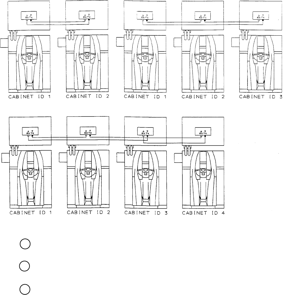
58
www.seuservice.com
www.seuservice.com
59
2P LINK 3P LINK
4P LINK
FIG. 20. 2 b Connecting method of the communication cable
Arrange the interconnected game machines. Keep a space between the game machines as wide as
possible.
Make the adjusters of all the game machines come into contact with the oor.
Connect the power cords and the earth wires.
10
9
11
Note: Actual Units differ from Image.

58
www.seuservice.com
www.seuservice.com
59
20 - 3 SETTING FOR COMMUNICATION PLAY
Change the game setting for each seat in manner so as to meet communication play. If the setting is
not correct, communication play cannot be played.
Turn the linked machines' power on.
Cause all of the machines to enter the test mode (see Section 9).
Select the GAME ASSIGNMENTS (see 9-3 d).
FIG. 20. 3 GAME ASSIGNMENTS Screen
Perform the COMMUNICATION MODE setting in the GAME ASSIGNMENTS screen. Set one of
the machines to MASTER and all others to SLAVE.
Perform the CABINET ID setting in the GAME ASSIGNMENTS screen. Set the machines to 1, 2,
3 and 4 sequentially in order starting from the leftmost machine facing the screen. Set every number
correctly without duplicating.
Cause all of the machines to exit from the test mode by selecting EXIT in the System Test Menu.
Exiting from the test mode causes the unit to perform the network check automatically. The Network
Check screen appears on the screen.
When nishing the network check successfully, the Advertise Screen appears. Normally the
network check nishes within several 10 seconds. If the screen does not proceed from the Network
Check screen, some sorts of errors such as the error of the setup, the error of cable connection, and
malfunctioning the communication cables, etc. can be considered.
GAME ASSIGNMENTS
GAME DIFFICULTY NORMAL
COMMUNICATION MODE NO LINK
HANDICAP ON
CABINET ID 1
> EXIT
SELECT WITH SERVICE BUTTON
AND PRESS TEST BUTTON
If it is set to SLAVE,
GAME DIFFICULTY and
HANDICAP are disappeared
on the screen.
SETTING FOR COMMUNICATION PLAY
1
2
3
4
8
7
6
5

60
www.seuservice.com
www.seuservice.com
61
20 - 4 CAUTIONS TO BE HEEDED DURING COMMUNICATION PLAY
During communication play, if communication is interrupted due to some cause, the
game is discontinued and the Network Check screen is displayed.
If one of the linked machines enters the Test Mode, all others display the Network
Check screen.
Even if it has set to the communication play, you can setup a different charge for
every machine.
A wrong charge setup may cause the problems of income and outgo.
Machine's operation when linked for communication play alters comparing to that of when
independently operated. Be careful of this point.
When any game machine is in a Test Mode, a Network Check screen appears on the other
game machines interconnected for a communication play. While a guest is using any one of the
interconnected game machines, therefore, do not activate a Test Mode even on the unused game
machine.
STOP
IMPORTANT!

60
www.seuservice.com
www.seuservice.com
61
17. Parts
5
6
7
4
3
2
18
Item # Part # Description Notes
1 999-1868 Marquee Plex Clear Goes over Syrine Marquee
2 999-1859 Speaker 25W RMS 50W Peak 4Ohm GR# A056-354-000
3 999-1867 Monitor Bezel
4 999-1871 Seat Small Hard Blue
5 999-1863 Floor Mat Back Section
6 999-1864 Floor Mat Front L or R
7 999-1866 Control Panel Cover Yellow
8 Local Purchase 18” CoolWhite Fluorescent 15W
9 999-0167 Leg Leveler
10 999-1900 Rear Wheels
9
10

62
www.seuservice.com
www.seuservice.com
63
4
2
1
Item # Part # Description Notes
1 999-1889 Coin Meter 0053-013-102
2 999-1860 1/4in shaft 450-2023 Mouser
4 999-1889 Coin Meter 0053-013-102
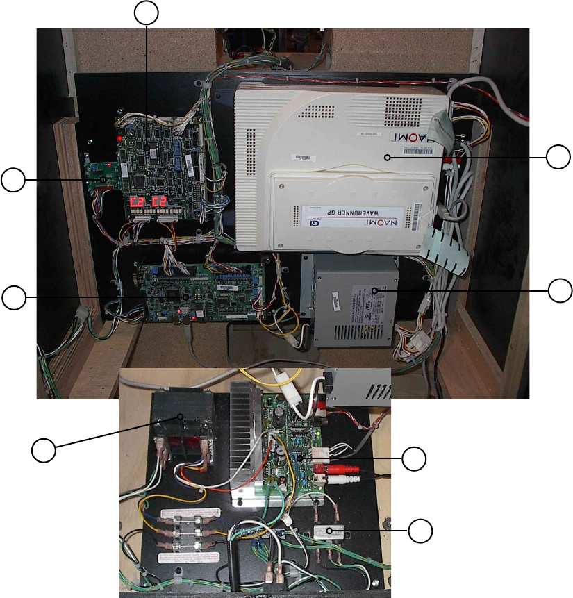
62
www.seuservice.com
www.seuservice.com
63
5
6
7
8
4
3
2
1
Item # Part # Description Notes
1 998-0195 Eliminator Board
2 838-12801 Drive BD WaveRunner
3 998-0190 Transformer 36 VCT @ 3.6A/A41-130-36
4 998-0194 Line lter GA Yun Pen YK06T1
5 838-13616 Audio Power Amp 2CH
6 400-5397-01 SW REGU for JVS VA
7 840-0064D-06 Assy Case Nao Wrg Std USA
8 837-13844-02 I/O Control BD 2 W/O 232C Dog
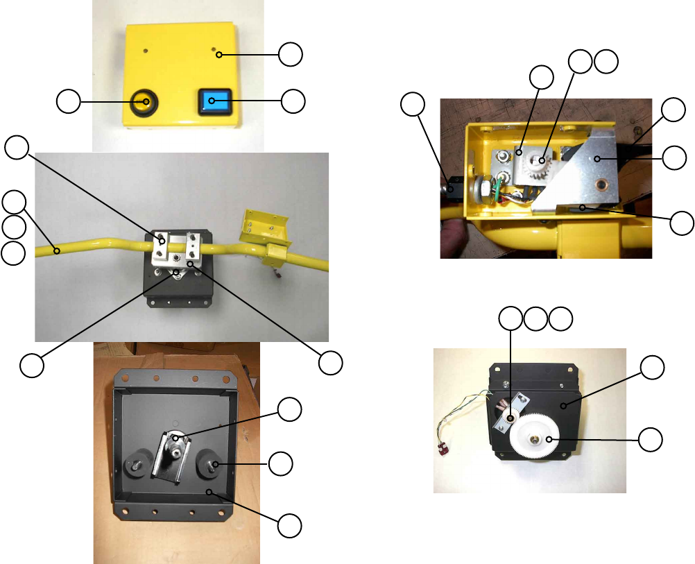
64
www.seuservice.com
www.seuservice.com
65
17
1514
13
12
11
5
6
78
9
10
4
3
2
1
21
20
19
18
Item # Part# Description Notes
1 999-1861 Start Button
2 999-1880 Handle Cover
3 999-1862 View Button
4 999-1881 Handle Bar Bracket
5 999-1882 Handle Bar
6 999-1883 Handle Grips
7 999-1884 Handle Shaft Bearing
9 999-1885 Handle Shaft
10 999-1886 Handle Stopper
11 999-1887 Handle Assembly Body
12 998-0196 Accel Harness
13 999-1889 Accel Pot Bracket
14 999-1892 Accel Pot Gear
15 999-1896 Accel Pot
16 999-1898 Accel Lever
17 999-1890 Accel Lever Bracket
18 999-1895 Accel Spring
19 999-1891 Steering Pot Bracket
20 999-1888 Handle Assembly Body Lower
21 999-1893 Handle Shaft Gear
22 999-1897 Steering Pot
23 999-1894 Steering Pot Gear
16
2322
24
64
www.seuservice.com
www.seuservice.com
65
22. WIRE COLOR CODE TABLE
THE WIRE COLOR CODE is as follow:
A PINK
B SKY BLUE
C BROWN
D PURPLE
E LIGHT GREEN
Wires other than those of any of the above 5 single colors will be displayed by 2 alphanumeric
characters.
1 RED
2 BLUE
3 YELLOW
4 GREEN
5 WHITE
7 ORANGE
8 BLACK
9 GRAY
If the right-hand side numeral of the code is 0, then the wire will be of a single color shown by
the left-hand side numeral (see the above).
Note 1: If the right-hand side alphanumeric is not 0, that particular wire has a spiral color code.
The left-hand side character shows the base color and the right-hand side one, the spiral
color.
<Example> 51. . . . . . . . . . . . .WHITE / RED
Note 2: The character following the wire color code indicates the size of the wire.
U: AWG16
K: AWG18
L: AWG20
None: AWG22
RED WHITE
66
www.seuservice.com
Notes:

Warranty
Your new Sega Product is covered for a period of 90 days from the date of shipment. This certies
that the Printed Circuit Boards, Power Supplies and Monitor are to be free of defects in workman-
ship or materials under normal operating conditions. This also certies that all Interactive Control
Assemblies are to be free from defects in workmanship and materials under normal operating condi-
tions. No other product in this machine is hereby covered.
Sellers sole liability in the event a warranted part described above fails shall be, at its option, to re-
place or repair the defective part during the warranty period. For Warranty claims, contact your Sega
Distributor.
Should the Seller determine, by inspection that the product was caused by Accident, Misuse, Ne-
glect, Alteration, Improper Repair, Installation or Testing, the warranty offered will be null and void.
Under no circumstances is the Seller responsible for any loss of prots, loss of use, or other dam-
ages.
This shall be the exclusive written Warranty of the original purchaser expressed in lieu of all other
warranties expressed or implied. Under no circumstance shall it extend beyond the period of time
listed above.

SEGA AMUSEMENTS USA, INC.
420-WRGCVT-UK REV 0
ADDENDUM TO SEGA WAVERUNNER GP STD MANUAL
This document is an addendum to the Sega WaveRunner GP STD Version USA Owner’s
Manual. It details the differences between the standard USA and European builds of the SEGA
WaveRunner unit. The Bill Of Materials lists the items that were changed, and the photographs
illustrate where the items are located on the unit.
Bill Of Materials for WRG-CVT-PROD
Seq. Part Number Description Qty
1 WH 100VAC A WH 100VAC A 1
2 WH AC IN WH AC IN 1
3 WH 100VAC B WH 100VAC B 1
4 WH EXCEL I/F WH EXCEL I/F 1
5 WH AUDIO POWER WH AUDIO POWER 1
6 XFMR NOB XFMR NOB 1
7 CONN BRD W/FUSE 6.3A CONN BRD W/FUSE 6.3A 1
8 FILTER IEC & SW 6A FILTER IEC & SW 6A 1
9 ASSY FL18W 110V ASSY FL18W 110V 1
10 CREDIT BOARD EXCEL CREDIT BOARD EXCEL 1
11 SR3 STD BODYSR3INGBB00050 SR3 STD BODYSR3INGBB00050 1
12 DOOR ASSY 40E-0512-00M DOOR ASSY 40E-0512-00M 1
13 AC BRKT WRG AC BRKT WRG 1
14 XFMR BASE WRG XFMR BASE WRG 1
15 FL TUBE 18W 600L FL TUBE 18W 600L 1
16 WH FL NOB WH FL NOB 1
17 WH METER LINK WH METER LINK 2
201 M4X12 W/FS PAS M4X12 W/FS PAS 4
202 4X1 S/TAP PAN PAS 4X1 S/TAP PAN PAS 5
203 M4X16 BLK WASHER M4X16 BLK WASHER 3
204 NO.6X5/8 S/TAP PAN PAS NO.6X5/8 S/TAP PAN PAS 4
401 420-WRGCVT-UK ADDENDUM WAVERUNNER CONV UK 1
Mains In Power Supply
6, 14
7
ADDENDUM WAVERUNNER CONV UK - 1 - 20 OCT 2003

420-WRGCVT-UK REV 0
ADDENDUM TO SEGA WAVERUNNER GP STD MANUAL
AC Bracket Fluorescent Light
Coin Handling
9
8 13
10 4
12
Not Shown SR3 Coin Mech.
ADDENDUM WAVERUNNER CONV UK - 2 - 20 OCT 2003