Arcade Zoofari Manual Service (ICE) 11 02 07 User
2013-11-28
User Manual: Arcade Zoofari Manual
Open the PDF directly: View PDF ![]() .
.
Page Count: 22

1
OWNERS AND SERVICE MANUAL
INNOVATIVE CONCEPTS IN ENTERTAINMENT INC.

2
TABLE OF CONTENTS
SAFETY & WARNINGS…………….……….…………..…..PAGE 3
• BEFORE YOU BEGIN
• INSTALLATION
• WARNING
GAME SETUP & FEATURES....…………….……………....PAGE 4 - 5
• PLAYER CONTROLS
• PLAYING THE GAME
• INITIAL GAME SETUP
DIAGNOSTIC, ADJUSTMENT & AUDIT MENU SYSTEM…...PAGE 6 - 12
• MENU SYSTEM
• STARTING THE MENU SYSTEM
• NAVIGATING THE MENU
• MAIN MENU
• VIEW COIN AUDITS
• VIEW TICKET AUDITS
• VIEW SYSTEM AUDITS
• COINAGE ADJUSTMENTS
• TICKET ADJUSTMENTS
• SYSTEM ADJUSTMENTS
• GAME ADJUSTMENTS
• RESET MENU
TROUBLESHOOTING...……………………………………….....PAGE 13 - 14
MAINTENANCE……………………………………………….…..PAGE 15 - 18
• CLEANING GLASS & MONITOR
• REPLACING MARQUEE LIGHT BULB
• GUN REPAIR
PARTS LISTING………………………………………………......PAGE 19
SCHEMATICS……………………………………………………..PAGE 20
JAMMA CONNECTOR PINOUT CHART……………………....PAGE 21
ICEDOC FZ9001
REVISION C 11-02-07

3
SAFETY AND WARNINGS
BEFORE YOU BEGIN
WARNING: WHEN INSTALLING THIS GAME, A GROUNDED A.C. RECEPTACLE MUST BE USED. FAILURE
TO DO SO COULD RESULT IN INJURY TO YOURSELF OR OTHERS. FAILURE TO USE A GROUNDED RE-
CEPTACLE COULD ALSO CAUSE IMPROPER GAME OPERATION, OR DAMAGE TO THE ELECTRONICS.
DO NOT DEFEAT OR REMOVE THE GROUNDING PRONG ON THE POWER CORD FOR THE SAME
REASON AS GIVEN ABOVE. USING AN IMPROPERLY GROUNDED GAME COULD VOID YOUR WAR-
RANTY.
HAVE A QUALIFIED ELECTRICIAN CHECK YOUR A.C. RECEPTACLE TO BE SURE THE GROUND IS
FUNCTIONING PROPERLY.
INSTALLATION
The game comes ready to play with just a few simple things to keep in mind.
1. Plug the game into the A.C. outlet and turn on power to the game. The switch for the game is located on a
power module on the outside rear of the game.
THIS GAME IS DESIGNED TO DISSIPATE STATIC ELECTRICITY THROUGH THE GROUNDING PLANE OF THE
GAME. IF THE A.C. GROUND DOES NOT WORK, THE GAME COULD DISCHARGE STATIC ELECTRICITY
THROUGH THE GAME CIRCUITRY, WHICH COULD CAUSE DAMAGE.
2. Make sure the game is level after installation. It is necessary to make sure the game is level for safety
concerns.
3. Check that the A.C. voltage rating on the back of the game matches the A.C. voltage of your location.
THE POWER SUPPLY IS NOT VOLTAGE ADJUSTABLE. TO OPERATE THE GAME AT VOLTAGES OTHER THAN
THOSE IT WAS DESIGNED FOR. PLEASE CONTACT OUR SERVICE DEPARTMENT FOR VOLTAGE CONVERSION
INFORMATION.
WARNING
DO NOT remove any of the components on the main board (e.g. compact flash and eproms) while
the game is powered on. This may cause permanent damage to the parts and the main board. Re-
moving any main board component part while powered on will void the warranty.
NOTE: THIS GAME IS INTENDED FOR INDOOR USE ONLY.
ON THE BACK PANEL OF THE GAME: WARNING: SHOCK HAZARD - DO NOT OPEN. REFER
SERVICING TO SERVICE PERSONNEL.

4
GAME SETUP AND FEATURES
Player Controls
To begin the game, insert the proper number of credits, and squeeze the Peanut Launcher button. There are
two Peanut Launchers, one for the left player and one for the right player.
Playing the Game
The objective of the game is to feed as many animals as possible within the game time in order to accumulate
points and tickets. Animals appear from all sides of the screen.
There are bonus items such as: red balloons – awards Double Points, blue balloons – awards more time,
Golden Roo – awards additional Bonus Points.
Initial Game Setup
The game is setup at the factory with the recommended factory settings. The following outlines the important
adjustments an operator may adjust during initial game setup. For more detailed instructions on setting these
adjustments, see Chapter 3.
Coins
Set the number of credits required to start the game. Also set the number of credits for each coin inserted in
coin mechanism 1 and coin mechanism 2. These settings are adjusted in the COINAGE ADJUSTMENTS
menu.
Tickets
Setup the points per ticket, minimum tickets paid, maximum tickets paid and ticket threshold. Also, setup
whether tickets should be dispensed while playing or at the end of the game. These settings are adjusted in
the TICKET ADJUSTMENTS menu.
Time Limit
Set the amount of game time for each start. These settings are adjusted in the GAME ADJUSTMENTS menu.
Points Per Ticket
Set the number of points required to earn one ticket.
Control Switches
The control switches are inside the front coin door.
Volume Up
Press the volume up button to increase the volume in the game and the attract mode. Pressing this button
when playing the game will increase the game volume. Pressing this button when the game is in the attract
mode will increase the attract mode volume.
Volume Down
Press the volume down button to decrease the volume in the game and the attract mode. Pressing this but-
ton when playing the game will decrease the game volume. Pressing this button when the game is in the at-
tract mode will decrease the attract mode volume.
Diagnostics Button
Press this button to go into the diagnostics MAIN MENU.
Coin Meters
The game has two mechanical meters. The left meter will be incremented by 1 each time a coin is dropped
into the coin mechanisms. The right meter will be incremented by 1 each time a ticket is dispensed.
5
GAME SETUP AND FEATURES
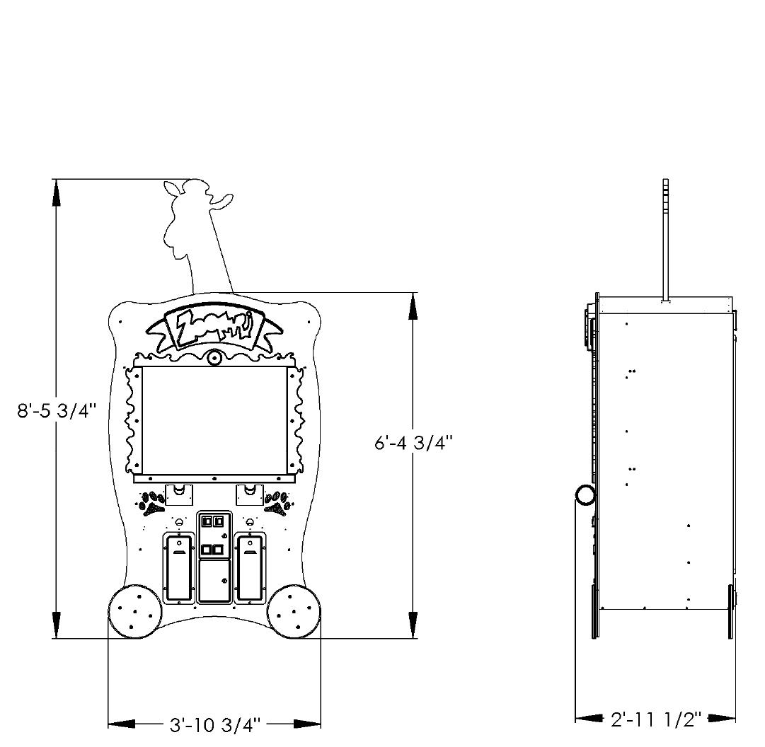
Game Setup Location
The sizes shown on the diagram below will help you determine the area required for your game, and where you might
want the game to be placed.

6
DIAGNOSTIC, ADJUSTMENT AND AUDIT MENU SYSTEM
Menu System
The game’s menu system is a series of on screen menus that allow the operator to setup and adjust the set-
tings. Each menu item leads to another menu, a list of data or provides the ability to modify the adjustment.
Starting the Menu System
Press the Diagnostics control switch inside the coin door to access the on screen menu system.
Navigating the Menu
Use the following buttons to navigate the menu system:
Volume Up button to move the cursor up.
Volume Down button to move the cursor down.
Diagnostic button to select.
Once an item has been selected, use the Volume Up/Volume Down button to change the settings. Once an item
has been changed, press the Diagnostic button to save the desired setting.
Main Menu
All system tests, audits and game adjustments are accessible from the MAIN MENU.
Zoofari 01.00.01 Serial #: 00105
MAIN MENU
SYSTEM TESTS MENU
COIN AUDITS
TICKET AUDITS
SYSTEM AUDITS
GAME AUDITS
COINAGE ADJUSTMENTS
TICKET ADJUSTMENTS
SYSTEM ADJUSTMENTS
GAME ADJUSTMENTS
RESET MENU
EXIT
USE VOL UP & VOL DN TO MOVE TEST TO SELECT

7
DIAGNOSTIC, ADJUSTMENT AND AUDIT MENU SYSTEM
Main Menu
Select SYSTEMS TEST at the MAIN MENU.
Zoofari 01.00.01 Serial #: 00105
SYSTEM TESTS MENU
GUN TEST & CALIBRATE
SWITCH INPUT TEST
VIDEO SCREEN TESTS
SOUND TEST
MAIN MENU
USE VOL UP & VOL DN TO MOVE TEST TO SELECT
Gun Test & Calibrate - Select GUN TEST &
CALIBRATE to calibrate the gun with the target on
the screen.
Switch Input Test - Select SWITCH INPUT TEST
to manually test all of the switch inputs. When in
this screen, activate the start button, select button,
test button, volume up, volume down, ticket sen-
sor 1, ticket sensor 2, coin 1, coin 2, game control
pad 1 and game control pad 2 to determine if the
game recognizes input from each.
Video Screen Tests - Select VIDEO SCREEN
TESTS to test the following: Screen Color, Screen
Size, Red Color, Green Color, Blue Color, and
White Color.
Sound Test - Select SOUND TEST to test various
game sounds and songs.
Zoofari 01.00.01 Serial #: 00105
VIDEO SCREEN TESTS
COLOR ADJUSTMENT
RED SCREEN
GREEN SCREEN
BLUE SCREEN
WHITE SCREEN
EXIT
USE VOL UP & VOL DN TO MOVE TEST TO SELECT
Color Adjustment – Displays multiple colors for
screen color adjustment.
Screen Size Adjustment – Displays grid for
screen size adjustments.
Red Screen – Displays full red for screen color
adjustments.
Green Screen - Displays full green for screen
color adjustments.
Blue Screen - Displays full blue for screen color
adjustments.
White Screen - Displays full white for screen
color adjustments.

8
DIAGNOSTIC, ADJUSTMENT AND AUDIT MENU SYSTEM
View Coin Audits
Select VIEW COIN AUDITS at the MAIN MENU to view coin data about the game.
View Ticket Audits
Select VIEW TICKET AUDITS at the MAIN MENU to view ticket data about the game.
Zoofari 01.00.01 Serial #: 00105
COINAGE AUDITS
COIN 1 0
COIN 2 0
PAID CREDITS 0
LIFETIME COIN COUNT 0
MAIN MENU
USE VOL UP & VOL DN TO MOVE TEST TO SELECT
Coin 1 – Number of coins inserted in coin
mechanism 1.
Coin 2 – Number of coins inserted in coin
mechanism 2.
DBV – Number of bills inserted in DBV mecha-
nism.
Paid Credits – Number of coins inserted in all
coin devices.
Lifetime Coin Count – Number of coins inserted
in all coin devices since the game has been in-
stalled. This WILL NOT be reset by CLEAR
COIN COUNTERS or RESTORE FACTORY
SETTINGS from the UTILITIES menu.
Zoofari 01.00.01 Serial #: 00105
TICKET AUDITS
TICKETS WON 0
AVERAGE TIX 0
TIX DISPENSED 1 0
TIX DISPENSED 2 0
HIGH TICKET 0
MAIN MENU
USE VOL UP & VOL DN TO MOVE TEST TO SELECT
Tickets Won – Total number of tickets won.
Average Tix – Average tickets dispensed per
game.
Tix Dispensed 1 – Total tickets dispensed from
dispenser 1.
Tix Dispensed 2 – Total tickets dispensed from
dispenser 2.
High Ticket – Highest number of tickets won.

9
DIAGNOSTIC, ADJUSTMENT AND AUDIT MENU SYSTEM
View System Audits
Select VIEW SYSTEM AUDITS at the MAIN MENU to view data about the game.
View Game Audits
Select VIEW GAME AUDITS at the MAIN MENU to view import data about the game.
NOTE: All Game Audits will be reset if you RESET AUDITS or RESTORE FACTORY SETTINGS from the
UTILITIES menu.
Zoofari 01.00.01 Serial #: 00105
SYSTEM AUDITS
UP TIME 0Y 0D 00:00:00
PLAY TIME 0Y 0D 00:00:00
PLAYER 1 STARTS 0
PLAYER 2 STARTS 0
MAIN MENU
USE VOL UP & VOL DN TO MOVE TEST TO SELECT
Up Time H:M:S - Total up time. Reported in
Hours, Minutes and Seconds.
Play Time H:M:S - Total up time. Reported in
Hours, Minutes and Seconds.
Player 1 Starts – Number of starts for Player 1.
Player 2 Starts – Number of starts for Player 2.
Zoofari 01.00.01 Serial #: 00105
GAME AUDITS
AVERAGE SCORE 0.00
HIGH SCORE 0
MAIN MENU
USE VOL UP & VOL DN TO MOVE TEST TO SELECT
Average Score – Average score per game
played. Use this setting to help determine ticket
settings from the TICKET UTILITIES menu.
High Score – Highest Score achieved.

10
DIAGNOSTIC, ADJUSTMENT AND AUDIT MENU SYSTEM
Coinage Adjustments
Select COINAGE ADJUSTMENTS at the MAIN MENU. Modify these coinage adjustments to change the
price of the game.
Ticket Adjustments
Select TICKET ADJUSTMENTS at the MAIN MENU. Modify these ticket adjustments to change the number
of tickets dispensed by the game.
Zoofari 01.00.01 Serial #: 00105
COINAGE ADJUSTMENTS
COIN SLOT 1 UNITS 1
COIN SLOT 2 UNITS 1
CREDITS TO START 1
MAXIMUM CREDITS OFF
FREE PLAY OFF
COMMON COIN/TIX METERS OFF
MAIN MENU
USE VOL UP & VOL DN TO MOVE TEST TO SELECT
Coin Slot 1 Units – Set the number of credits
received when a coin or token is inserted in coin
mechanism 1. Set from 1 – 20 or “Off”.
Coin Slot 2 Units – Set the number of credits
received when a coin or token is inserted in coin
mechanism 2. Set from 1 – 20 or “Off”.
Credits to Start – Set the number of credits re-
quired to start a game. Set from 1 – 10.
Maximum Credits - Set the maximum of credits
allowed. Set from 1 - 99 or “Off”.
Free Play – If set to ‘Yes’ the game is set on free
play and no coins or credits will be required to
play.
Common Coin / Tix Meters – Set to “On” to
share meters, “Off” to use both meters.
Zoofari 01.00.01 Serial #: 00105
TICKET ADJUSTMENTS
TICKET DISPENSER ON
TICKET MINIMUM 1
TICKET MAXIMUM OFF
IDEAL PAYOUT 10
DISPENSE WHILE PLAYING ON
MAIN MENU
USE VOL UP & VOL DN TO MOVE TEST TO SELECT
Tickets Dispenser – This setting turns the ticket
dispenser on or off.
Tickets Minimum – This setting determines the
minimum number of tickets to be dispensed for
each game played. Set from 1 – 10. If the game
does not have a ticket dispenser, set to 0.
Tickets Maximum – This setting determines the
maximum number of tickets to be dispensed for
each game played. Set from 1 – 100 or “Off”. If
the game does not have a ticket dispenser, set to
0.
Ideal Payout - This setting determines the ideal
ticket payout per game. Set from 0 - 100 or “Off”.
Dispense While Playing – Set to ‘Off’ to dis-
pense tickets at the end of each game. Set to
‘On’ to dispense tickets as they are earned dur-
ing game play.

11
DIAGNOSTIC, ADJUSTMENT AND AUDIT MENU SYSTEM
System Adjustments
Select SYSTEM ADJUSTMENTS at the MAIN MENU. Modify these values to change the mode and volume
level of the game.
Game Adjustments
Select GAME ADJUSTMENTS at the MAIN MENU. Modify these game adjustments to change the way the
game functions.
Zoofari 01.00.01 Serial #: 00105
SYSTEM ADJUSTMENTS
ATTRACT SOUND ON
MINIMUM VOLUME 0
MAIN MENU
Play sounds in attract mode
USE VOL UP & VOL DN TO MOVE TEST TO SELECT
Attract Sound – Set to “On” to have attract
mode play while game is idle. Set to “Off” if no
attract mode is desired. Set to “Occasionally if
attract mode is desired some of the time.
Minimum Volume – Minimum volume setting for
the game. Set from 0 – 255. The higher the set-
ting the higher the volume.
Zoofari 01.00.01 Serial #: 00105
GAME ADJUSTMENTS
GAME TIME 30
BONUS TIME 10
MAXIMUM ANIMALS 3
POINTS PER TICKET 100
PEANUT STYLE ORANGE/GREEN
MAIN MENU
Time is seconds of one play
USE VOL UP & VOL DN TO MOVE TEST TO SELECT
Game Time – Game Time. Minimum time = 1
seconds, Maximum = 60 seconds.
Bonus Time – Frequency of the Time Bonus
coming out. Set from 1 - 30 seconds.
Maximum Animals - Maximum number of ani-
mals on the screen at one time. Set from 1 - 10.
Points Per Ticket - Number of points required to
win one ticket. Set from 10 - 1000.
Peanut Style - Color of peanuts used to feed the
animals. Choose from: ORANGE/GREEN,
BLUE/YELLOW or CLASSIC.

12
DIAGNOSTIC, ADJUSTMENT AND AUDIT MENU SYSTEM
Reset Menu
Select RESET MENU at the MAIN MENU. Select these options to reset game audits.
I.C.E. Parts/Service Dept.
Phone #: (716) - 759 – 0360
Fax #: (716) – 759 – 0884
NORMAL BUSINESS HOURS ARE:
MONDAY - FRIDAY, 9:00 AM TO 6:00 PM EST
Zoofari 01.00.01 Serial #: 00105
RESET MENU
RESET CREDITS
RESET TICKETS
RESET AUDITS
RESET ADJUSTMENTS
FACTORY RESET
MAIN MENU
USE VOL UP & VOL DN TO MOVE TEST TO SELECT
Reset Credits – Resets credits stored in the
game.
Reset Tickets – Resets the number of tickets
won.
Reset Audits – Resets all game audits.
Reset Adjustments – Resets all adjustments
made to the game.
Factory Reset – Resets the game to factory de-
faults.

13
TROUBLESHOOTING
Troubleshooting
CAUTION
This game uses complex electronic components that are very sensitive to static electricity. Observe precau-
tions below before handling these electronics. Failure to do so may void the warranty and damage electronic
assemblies.
Before servicing electronics, turn off AC power to the game. Wait for capacitors to discharge.
DO NOT remove any of the components on the main board (e.g. compact flash and eproms) while the game is
powered on. This may cause permanent damage to the parts and the main board.
Before touching or handling electronic assemblies, discharge static electricity on your body. To discharge this
static, begin by connecting the line cord to a grounded outlet. Don’t turn on the game. Next, touch the safety
ground stud of the power supply chassis.
Store electronic assemblies in an anti-static area. Use anti-static bags to store or transport the game circuit boards.
Don’t remove or connect electronic assemblies when cabinet power is on. Otherwise, you’ll damage electronic as-
semblies and void the game’s warranty.
After you complete maintenance or service, replace ground wires, shields, safety covers and install and tighten
ground and mounting screw.
Video game monitors generate and store potentially high voltages. Avoid touching any part of the monitor until
power has been off for some time. A picture tube can maintain a hazardous charge for up to several days. Only
qualified technicians should service monitors.
Game Is Non-Functional
1. Verify that the game power switch is turned on.
3. Verify that the line cord connector is firmly and correctly seated into the power entry module of AC power chassis.
4. Verify that correct AC line voltage is present at the outlet
5. Verify that the JAMMA wire harness connector is firmly and properly seated to the mating JAMMA PCB edge con-
nector. DO NOT remove or install JAMMA connector when power is turned on. Doing so will damage the CPU
assembly and void the warranty.
6. Verify that the DC power supply voltages at the game CPU assembly are set as follows. The following voltages
should be set when the game CPU assembly is connected and the game is powered on.
+5V: +4.9V - +5.1V /// +12V: +11.5V - +12.5V //// -5V: -4.75V - -5.25V
7. Verify that the non-JAMMA connectors are attached at the proper location and are firmly seated.
8. Verify that the game DIP switches are set properly.
9. If game sounds can be heard but no picture is seen on the monitor, see monitor is non functional
2. Verify that earth ground is properly connected and all exposed metal points are properly grounded.
14
TROUBLESHOOTING
Monitor Is Non-Functional
Sound Is Non-Functional
Game Controls Are Non-Functional
1. Verify the cabinet has AC line voltage present at the monitor and has earth ground connected.
2. Verify that the video is properly connected from the game boards output to the monitor input.
3. Verify that the monitor remote adjustment board is properly installed and connected to the monitor chassis. Ver-
ify that brightness and contrast are set above their minimum levels.
4. Check fuses on monitor chassis. Replace fuse or chassis as necessary.
5. Verify that the game is using a low-res monitor.
1. Verify the cabinet wiring is correct. Ensure that the speakers are properly connected to the audio wires from
the JAMMA connector.
2. Verify that the power is providing:
+5V: +4.9V - +5.1V
+12V: +11.5V - +12.5V
-5V: -4.75V - -5.25V
3. Verify that the above listed voltages are present at the correct JAMMA connector pins.
4. Verify that the game volume has been turned up.
1. Verify that the each individual switch is working by doing the SWITCH INPUT TEST under the SYSTEM
TESTS MENU.
2. Verify that the each individual signal wire for each switch is connected.
15
MAINTENANCE / REPAIR
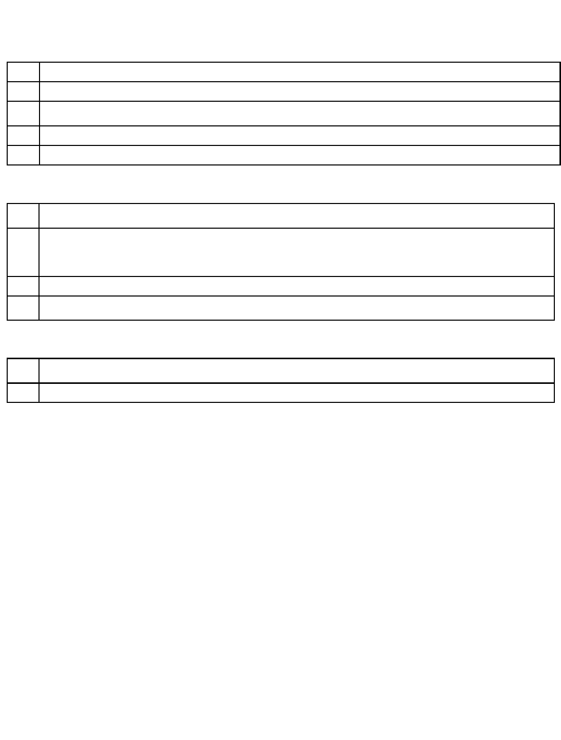
To Clean Glass and Monitor
1. Remove item no. 2.
2. Remove item no. 3.
3. Remove glass (item no. 1)
4. Assemble in reverse.
ITEM
NO. PART
NO. DESCRIPTION QTY.
1 FZ3027 GLASS 1
2 FZ3032 FRAME TOP 1
3 FZ3031 FRAME SIDE 2
4 FZ3030 FRAME BOTTOM 1
5 6281 1/4-20 X 1” LG. BHCS ZINC 12
6 6020 #10 FLAT WASHER ZINC 12
16
MAINTENANCE / REPAIR
ITEM
NO. PART
NO. DESCRIPTION QTY.
1 FZ3068 PANEL (LIGHT BOARD) 1
2 BW250 BULB SOCKET 1
3 BW2017 BULB PLASTIC CLIP 1
4 BW2018 BULB PLASTIC SUPPORT 1
5 8312 BULB PL-L 1
6 CS8449X BALLAST ASSEMBLY 1
7 6071 #6 x 1/2 SELF-TAP (BLACK) 2
8 6019 #6 DRYWALL SCREW 1" 3
To Replace Light Bulb In Marquee
1. Remove back panel of cabinet.
2. Locate above light fixture assembly.
3. Remove 2 mounting nuts located in above diagram.
4. Remove assembly and replace bulb.
5. Assemble in reverse.
MOUNTING
NUT
MOUNTING
NUT
17
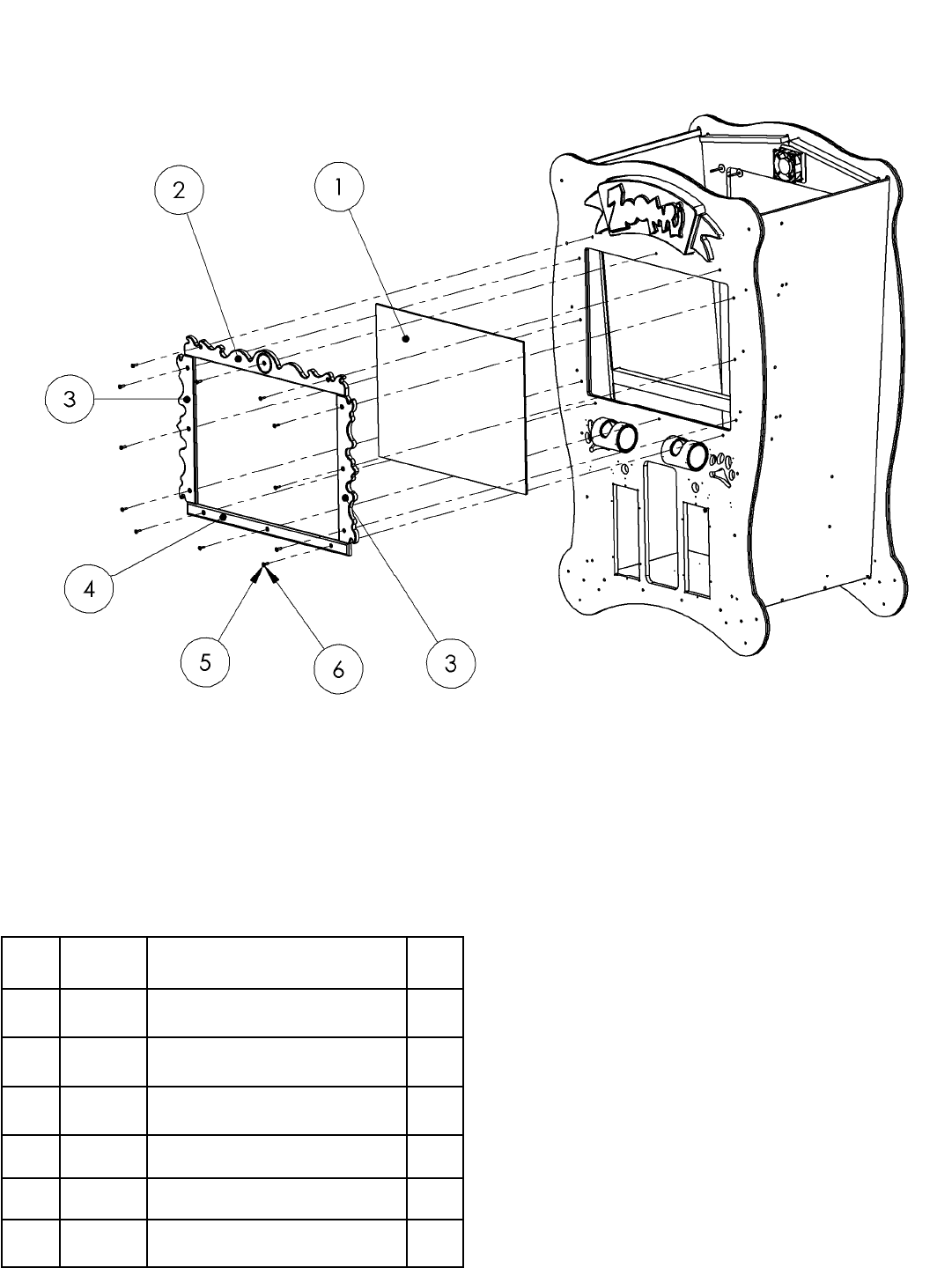
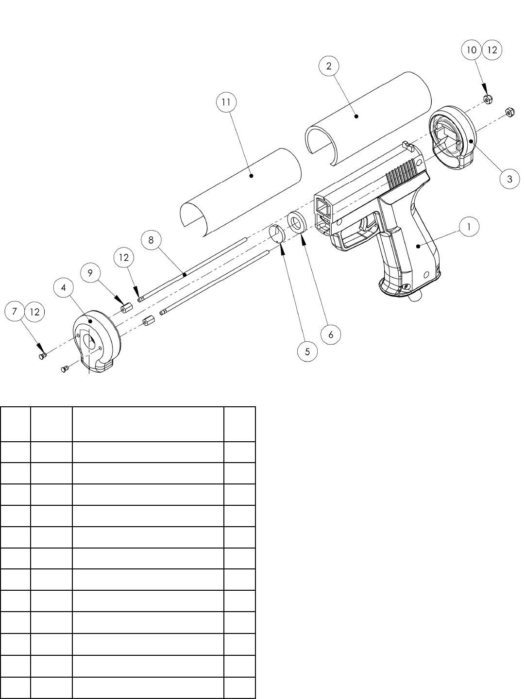
MAINTENANCE / REPAIR
ITEM
NO. PART
NO. DESCRIPTION QTY.
1 FZ2011 SHOOTER HOUSING (YELLOW) 1
2 FZ3010 SHOOTER TUBE 1
3 FZ3011 SHOOTER BUTT 1
4 FZ3016 SHOOTER POINT 1
5 PT2013 LENS (GUN) 96-0068-00 1
6 6251 NYLON WASHER 1
7 6269 6-32 x 1/4 PEM STUD 2
8 FZ1050 6-32 THREADED ROD 2
9 640 6-32 x 3/8 HH SPACER (METAL) 2
10 6324 6-32 ACORN NUT 2
11 FZ7011 DECAL, GUN BARREL 1
12 THREAD LOCK A/R
CUSTOM LENS
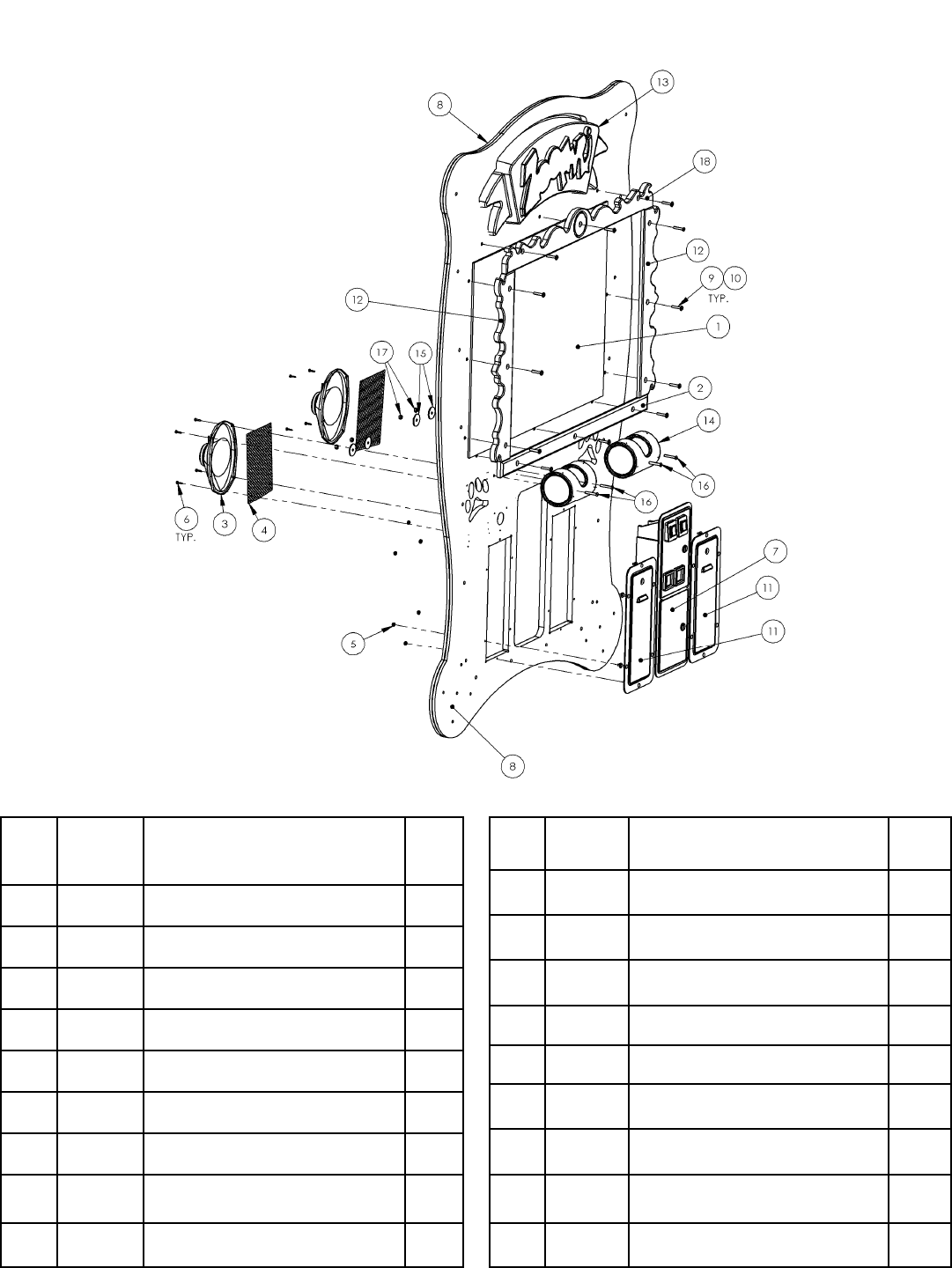
18
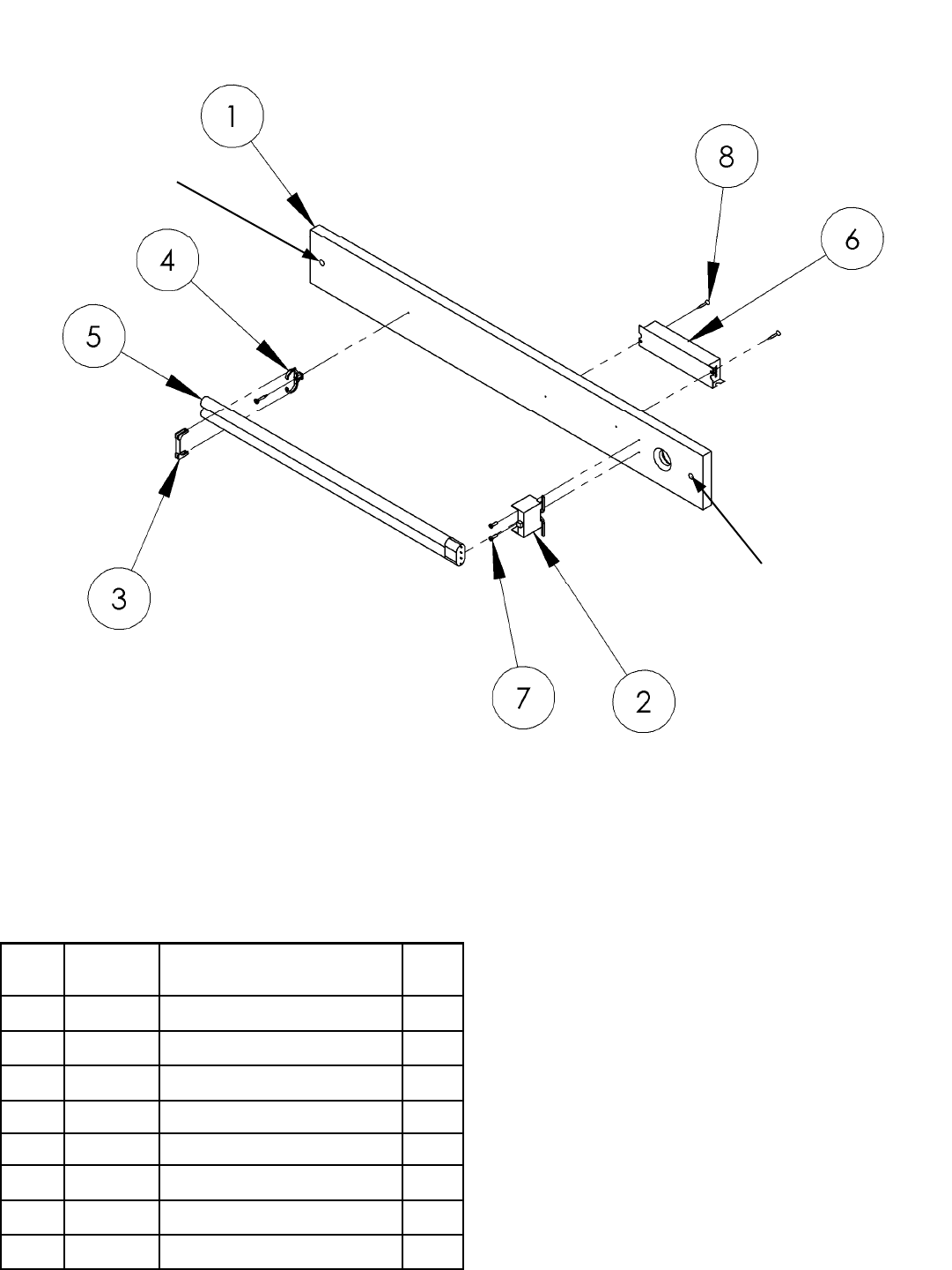
MAINTENANCE /REPAIR
ITEM
NO. PART
NO. DESCRIPTION QTY.
10 6020 #10 FLAT WASHER ZINC 12
11 5008 TICKET DOOR (HAPP) 2
12 FZ3031 FRAME SIDE 2
13 FZ7027F MARQUEE 1
14 FZ3071 PEANUT BARREL ASSEMBLY 2
15 6070 1/4 X 1-1/2” X .090 F-WASHER 4
16 6220 1/4-20 X 1 3/4” BSHCS (BLACK) 4
17 PC60604 1/4-20 NYLOCK NUT 4
18 FZ3032 FRAME TOP 1
ITEM
NO. PART
NO. DESCRIPTION QTY.
1 FZ3027 GLASS 1
2 FZ3030 FRAME BOTTOM 1
3 FG2007 6 X 9 SPEAKER (SHIELDED) 2
4 FZ1019 SPEAKER GRILL 2
5 6040 10-24 KEP NUT 12
6 655 #8 X 3/4” SQ. DRIVE SCREW 8
7 5001 COIN DOOR SET 1
8 FZ3050X CABINET FRONT ASSEMBLY 1
9 6281 1/4-20 X 1.5” LG. BHCS ZINC 12

19
PARTS LISTINGS
Mechanical Parts
211 Low Ticket Switch
1024 Ticket Bin
5001 Coin Door
5008 Ticket Door
FZ2011 Gun - No Recoil - Yellow
FZ3000 Wheel (Back Left)
FZ3001 Wheel (Front)
FZ3010 Shooter Tube
FZ3027 Monitor Glass
FZ3037 Wheel (Back Right)
FZ3071 Barrel & End Cap Assembly
FZ7027 Marquee
PT2011X Gun - No Recoil - Blue
Electrical Parts
8312 PL-L Bulb
8716 Flash Card - Compact
CS8449X Ballast (WH-3)
DD2364X Fan
FG2007 Speaker 6” X 9”
MON29CF Monitor – 29” Flat Screen
RN2034FZX PCB (Main)
WA2010 Power Supply
Graphics and Decals
FZ7000 Decal - Gorilla Side
FX7001 Decal - Cartouche
FZ7002 Decal - Side (Feed The Animals…..)
FZ7003 Decal - Cabinet Front
FZ7004 Decal - Wheels
FZ7005 Decal - Monitor Bezel
FZ7006 Decal - Side (Lower Strip)
FZ7008 Decal - Monitor Peanuts
FZ7009 Decal - Barrel
FZ7010 Decal - Barrel Peanuts
FZ7013 Decal - Instructions
FZ7024 Decal - ICE Logo
FZ7025 Decal - Giraffe Head - Front
FZ7026 Decal - Giraffe Head - Rear
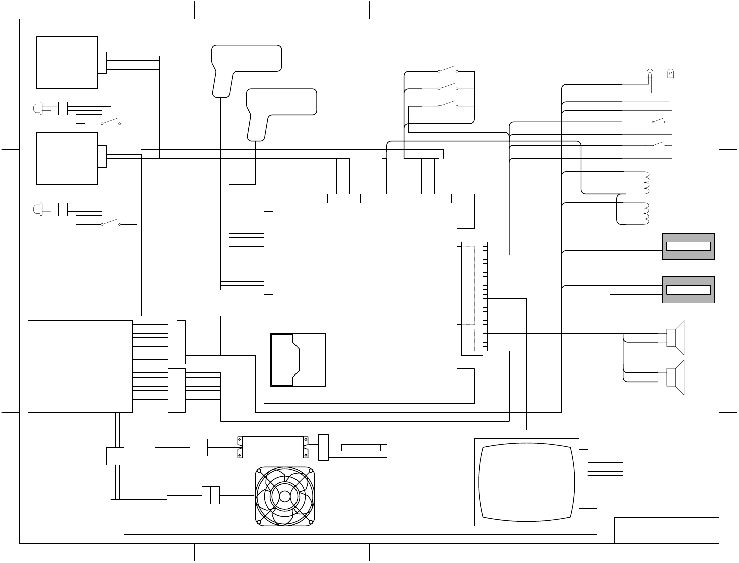
20
D
C
B
A
4321
D
C
B
A
4321
TITLE
FZ1000X - ZOOFARI
COMPACT
FLASH
1
2
3
4
5
6
7
8
9
10
11
1
2
3
4
5
6
1
2
3
4
5
8
7
6
5
4
3
2
1
8
7
6
5
4
3
2
10000000000
black
red
0000000000
red
black
COIN
TICKET
orange
black
orange
black
black
white
coin lamps
Coin Switch 1
Coin Switch 2
black
white/black
orange
orange
tan
tan
Lockout Coils
WA2010
POWER SUPPLY red/gray
brown/gray
red/white
brown/white
1
2
3
4
5
6
7
8
9
1
2
3
4
5
6
7
8
9
1
2
3
4
5
6
7
8
9
1
2
3
4
5
6
7
8
9
RED * 2
RED * 2
BLACK *2
BLACK * 2
BLACK * 2
WHITE * 2
YELLOW * 2
black * 2
ORANGE
TICKET
DISPENSER
#1
TICKET
DISPENSER
#2
1
2
3
4
1
2
3
4VOL. DOWN
VOL. UP
DIAGNOSTIC
PEANUT
SHOOOTER 1
PEANUT
SHOOTER 2
1
2
3
CS8449X
BALLAST
3
2
1
1
2
3
1
2
3
#PP250X - SOCKET
#8312 - BULB PL-L 40W
MONITOR
RN2034FZX
MAIN BOARD
1
2
3
4
5
6
yellow/red
yellow/green
yellow/blue
yellow/black
yellow
yellow+yellow/white
BLACK
GREEN/YELLOW
WHITE
BROWN
GREEN/YELLOW
BLUE
BROWN
GREEN/YELLOW
BLUE
BROWN
GREEN/YELLOW
BLUE
blue
black
white
red
blue
black
white
red
white/brown
white/red
white/orange
black
black
black
black
KEY # 2991
white/brown
white/red
blue
tan
tan/black
black
blue/white
violet/white
violet/blue
orange
#8556 - RED LED
1
2
violet/blue
black*2
violet/white
orange*2
orange
violet/green
LOW TICKET SWITCH
blue
black*2
blue/white
orange*2
#8556 - RED LED
1
2
orange
violet/green
LOW TICKET SWITCH
white/green
white/yellow
1
2
3
BROWN
GREEN/YELLOW
BROWN
1
2
3
BROWN
GREEN/YELLOW
BLUE
DD2364X
FAN ASSEMBLY
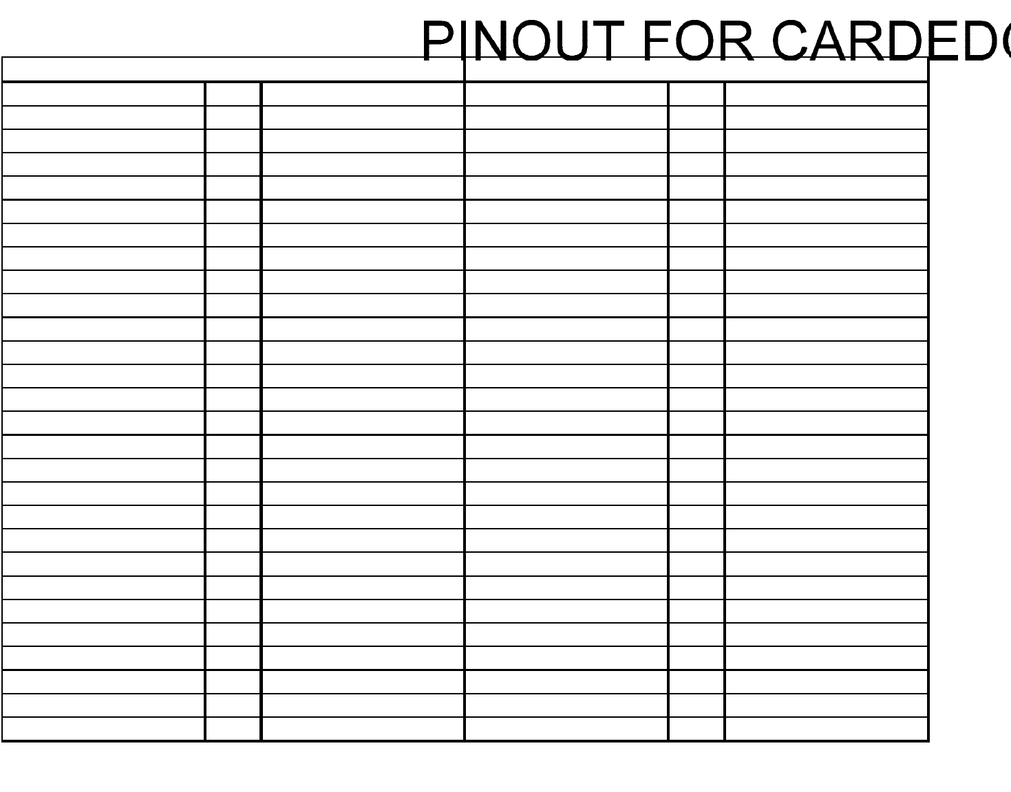
21
Ground 1 BLACK Ground A BLACK
Ground 2 BLACK Ground B BLACK
+ 5 Volts 3 RED + 5 Volts C RED
+ 5 Volts 4 RED + 5 Volts D RED
- 5 Volts 5 WHITE - 5 Volts E WHITE
+ 12 Volts 6 YELLOW + 12 Volts F YELLOW
KEY 7 KEY KEY H KEY
Coin 8 white/green Ticket J white/yellow
NC 9 Dummy Pin NC K Dummy Pin
Left Speaker + 10 red/gray Left Speaker - L brown/gray
Right Speaker + 11 red/white Right Speaker - M brown/white
Red Video 12 yellow/red Green Video N yellow/green
Blue Video 13 yellow/blue Composite Sync P yellow/white
Video Ground 14 yellow/black Service R Dummy Pin
Diagnostics 15 white/orange Tilt S Dummy Pin
Coin 1 16 white Coin 2 T white/black
Player 1 Start 17 Dummy Pin Player 2 Start U Dummy Pin
Player 1 Select 18 Dummy Pin Player 2 Up V Dummy Pin
Player 1 Down 19 Dummy Pin Player 2 Down W Dummy Pin
Player 1 Left 20 Dummy Pin Player 2 Left X Dummy Pin
Player 1 Right 21 Dummy Pin Player 2 Right Y Dummy Pin
Player 1 Button 1 22 Dummy Pin Player 2 Button 1 Z Dummy Pin
Player 1 Button 2 23 Dummy Pin Player 2 Button 2 a Dummy Pin
Player 1 Button 3 24 Dummy Pin Player 2 Button 3 b Dummy Pin
Player 1 Button 4 25 Dummy Pin Player 2 Button 4 c Dummy Pin
NC 26 Dummy Pin NC d Dummy Pin
Ground 27 black Ground e Dummy Pin
Ground 28 BLACK Ground f BLACK
COMPONENT SIDE SOLDER SIDE

Contacts at SEGA
Machine Sales
Telephone: +44 (0) 208 391 8090
Fax: +44 (0) 208 391 8099
www.sega-amusements.co.uk
SEGA Spares
Telephone: +44 (0) 208 391 8060
Fax: +44 (0) 208 391 8096
www.segatotalsolutions.com
Customer Services
Telephone: +44 (0) 208 391 8065
Fax: +44 (0) 208 391 8096
