Arcadyan Technology AIOS4-0S HEOS 4.X Platform Module User Manual
Arcadyan Technology Corporation HEOS 4.X Platform Module
Contents
- 1. User Manual
- 2. OEM Manual
User Manual

AIOS-4.0 Page : 1
Arcadyan Corporation
User manual
Arcadyan Model: AIOS4.0S, AIOS4.0V, AIOS4.0R, AIOS4.0F

AIOS-4.0 Page : 2
Arcadyan Corporation
Table of Contents
0. SUMMARY OF THIS PRODUCT ........................................................................................................ 3
1. SPECIFICATION................................................................................................................................. 3
1-1 Basic Specification................................................................................................................................ 3
1-2 Certification Requirement...................................................................................................................... 4
2. DETAIL SPECIFICATION ....................................................................................................................... 5
2-1. Product Specification............................................................................................................................ 5
2-2. FW Product Specification ..................................................................................................................... 5
2-3. I/O Specification .................................................................................................................................. 5
2-3-1. LED Specification...................................................................................................................... 5
2-3-2. Connector Specification.............................................................................................................. 6
2-3-3. GPIO Map................................................................................................................................. 7
2-3-4. Power Sequence......................................................................................................................... 9
2-3-5. Power Consumption ................................................................................................................. 10
2-3-6. ESD Transient SPEC................................................................................................................ 10
2-3-7. PCB Dimension .............................................................................................................................. 10
3. WIRELESS SPECIFICATION ........................................................................................................... 11
3-1 Radio 0 specification ........................................................................................................................... 11
3-1-1 WLAN0 specification................................................................................................................ 11
3-1-2 Bluetooth specification.............................................................................................................. 13
3-2 Radio 1 specification ........................................................................................................................... 13
3-2-1 WLAN1 specification................................................................................................................ 13
FCC & IC Statement:......................................................................................................................... 14
AIOS-4.0 Page : 3
Arcadyan Corporation
0. SUMMARY OF THIS PRODUCT
This product is AIOS-4.0X. There are 4 types of different audio product, AIOS4.0S, AIOS4.0V, AIOS4.0R,
AIOS4.0F
1. SPECIFICATION
1-1 Basic Specification
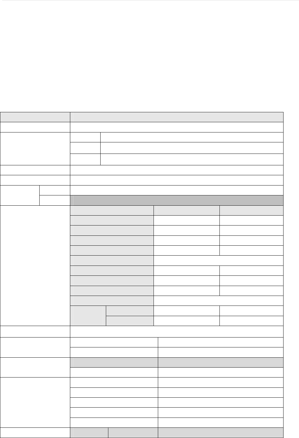
2. Item Contents
Manufacture Arcadyan
D&M JP AIOS-4.0X
TYM AIOS-4.0X
Shipment Name
ANAM AIOS-4.0X
Product Name Wireless LAN Network Module
Series Name Lego module
JP AIOS-4.0 Model Name
US -
SOC Vendor Model name
CPU Broadcom BCM58305
2.4GHz MAC/BB/RF Broadcom BCM4356
2.4GHz PA(Tx) Refer wireless spec
2.4GHz LNA(Rx) Refer wireless spec
2.4GHz BPF(Rx) Co-layout
5GHz MAC/BB/RF Broadcom BCM4356
5GHz PA(Tx) Refer wireless spec
5GHz LNA(Rx) Refer wireless spec
5GHz BPF(Rx) Co-layout
WAN None none
Chip
PHY
LAN Broadcom BCM58305 internal
OS
ODM Arcadyan
FW
FW spec Broadcom SDK AxC-FC2 for function test
Driver Utility
Driver/Utility
ODM Arcadyan
Refer wireless spec
Support Band
Item Link Rate Number of ports
AIOS-4.0 Page : 4
Arcadyan Corporation
Item Link Rate Number of ports
LAN 10/100M 1 LAN 10/100/1000M 1
Interface
USB 2.0 1
Supply Voltage 5V
Power consumption 9W
Weight Under 78g
Dimensions 87 x 74 x 1.6mm
Temperature 0~70 degC
Operating Environment
Humidity 10~85 % (Non Condensing)
Temperature -10~85 degC
Humidity 10~85 % (Non Condensing)
Design life time 5years at 25 degrees
Made in China
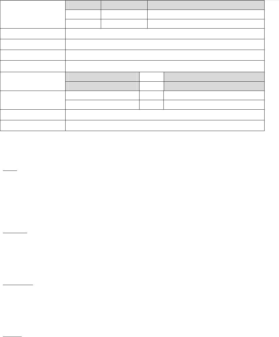
1-2 Certification Requirement
USA
FCC Parts15B/15C/15E
FCC ID Approval( with DFS)
DFS/TPC
FCC Bulletin OET-65C
Canada
IC certificate
RSS RSS-247 RF report
RSS-102 MPE report
European
CE EN 300 328/EN 301 893
EN 301 489-1/-17
EN62311
Japan
ARIB STD-T66 / ARIB STD-T71 TELEC ID
AIOS-4.0 Page : 5
Arcadyan Corporation
2. Detail Specification
2-1. Product Specification
Items Contents
Vendor Broadcom
Parts number BCM58305
CPU
Operation frequency 1.25GHz Dual Core
Type DDR3L
Width 16bit
Operation Freq 1600MHz
RAM
Capacity 256MB
Type NAND Flash
I/O speed 20ns
ROM
Capacity 4Gb
Number of port 2
Type Color Connector
Vendor Chip
MAC Broadcom BCM58305
Chip
PHY Broadcom BCM58305
Wired
LAN
Standard 10BASE-T/100BASE-Tx/1000BASE-Tx
- Standard USB2.0 -
USB
- Bus power 5V -
2-2. FW Product Specification
For detail, refer to FW Specification Requirement sheet
2-3. I/O Specification
2-3-1. LED Specification
Items Name Color
LED Interface POWER/DIAG Green
AIOS-4.0 Page : 6
Arcadyan Corporation
2-3-2. Connector Specification
Items Contents
Female 40x2p
Box header connector Female 21x2p
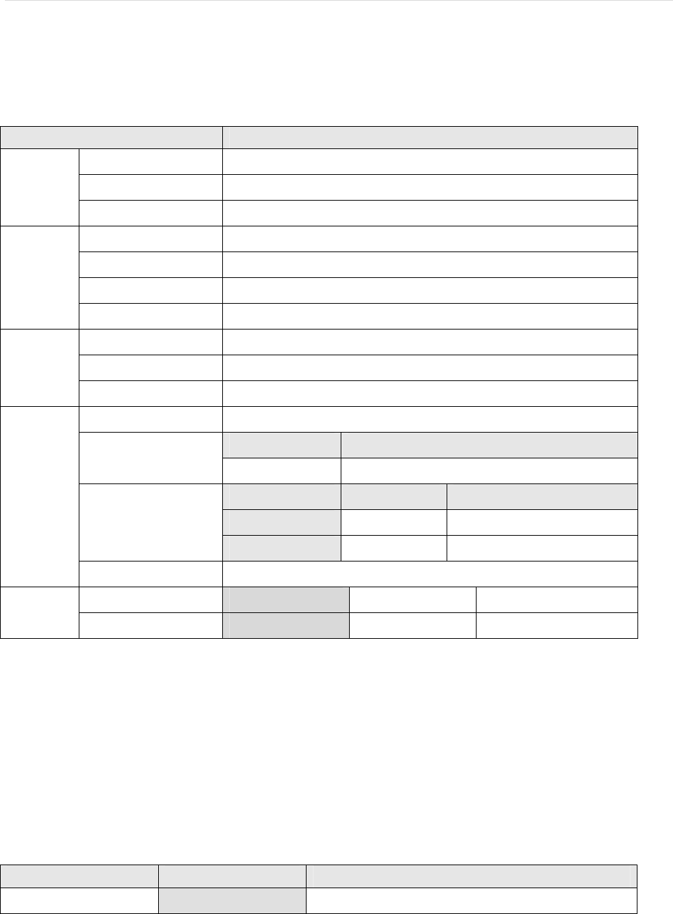
J9091 – 40x2 pin connector
Pin Define Pin Define Pin Define Pin Define
1 PWM0 2 PWM1 41 SPI0_MISO 42 TDP_PHY0_CH0
3 PWM2 4 VDD5_IN 43 GND 44 GND
5 VDD5_IN 6 VDD5_IN 45 SPI0_CLK 46 SPI0_MOSI
7 MCLK_I2S_0 8 SPDIF_OUT 47 UART1_TX 48 UART1_RTS
9 GND 10 GND 49 UART1_RX 50 UART1_CTS
11 WS_I2S_0 12 SDIN_I2S_0 51 USB2_VBUS_EN 52 PWM3
13 BITCLK_I2S_0 14 SDOUT_I2S_0 53 GPIO_02 54 GPIO_03
15 GND 16 GND 55 GPIO_04 56 GPIO_05
17 WS_I2S_1 18 SDIN_I2S_1 57 GPIO_06 58 GPIO_07
19 BITCLK_I2S_1 20 SDOUT_I2S_1 59 GPIO_08 60 GPIO_09
21 GND 22 GND 61 GPIO_10 62 GPIO_11
23 WS_I2S_2 24 SDIN_I2S_2 63 GPIO_12 64 GPIO_13
25 BITCLK_I2S_2 26 SDOUT_I2S_2 65 GPIO_14 66 GPIO_15
27 GND 28 GND 67 GPIO_16 68 GPIO_17
29 I2C0_SDA 30 USB2_P2_DM 69 GPIO_18 70 GPIO_19
31 I2C0_SCL 32 USB2_P2_DP 71 GPIO_20 72 GPIO_21
33 GND 34 GND 73 GPIO_22 74 RESET_BUTTON
35 I2C1_SDA 36 TDN_PHY0_CH1 75 GPIO_24 76 GPIO_25
37 I2C1_SCL 38 TDP_PHY0_CH1 77 ADC_AUXIN_0 78 ADC_AUXIN_1
39 SPI0_SS 40 TDN_PHY0_CH0
79 ADC_AUXIN_2 80 ADC_AUXIN_3
J9092 – 2x21 pin connector
Pin Define Pin Define Pin Define Pin Define
1 LCD_CLCP 2 GND 23 LCD_CLD15 24 LCD_CLD14
3 GND 4 LCD_CLFP 25 LCD_CLD17 26 LCD_CLD16
5 LCD_CLLP 6 LCD_CLAC 27 LCD_CLD19 28 LCD_CLD18
7 GND 8 LCD_CLD00 29 LCD_CLD21 30 LCD_CLD20
9 LCD_CLD01 10 LCD_CLD02 31 LCD_CLD23 32 LCD_CLD22
11 LCD_CLD03 12 LCD_CLD04 33 GND 34 GND
13 LCD_CLD05 14 LCD_CLD06 35 TDN_PHY1_CH0 36 TDN_PHY1_CH1
15 LCD_CLD07 16 LCD_CLD08
37 TDP_PHY1_CH0 38 TDP_PHY1_CH1
AIOS-4.0 Page : 7
Arcadyan Corporation
17 LCD_CLD09 18 LCD_CLD10 39 TDN_PHY1_CH2 40 TDN_PHY1_CH3
19 LCD_CLD11 20 GND 41 TDP_PHY1_CH2 42 TDP_PHY1_CH3
21 LCD_CLD13 22 LCD_CLD12
J4 - Console connector Footprint Pin Define
Pin Pin Define
1 VDD3_3
2 UART3_TX
3 UART3_RX
4 GND
J2 - JTAG connector Footprint Pin Define
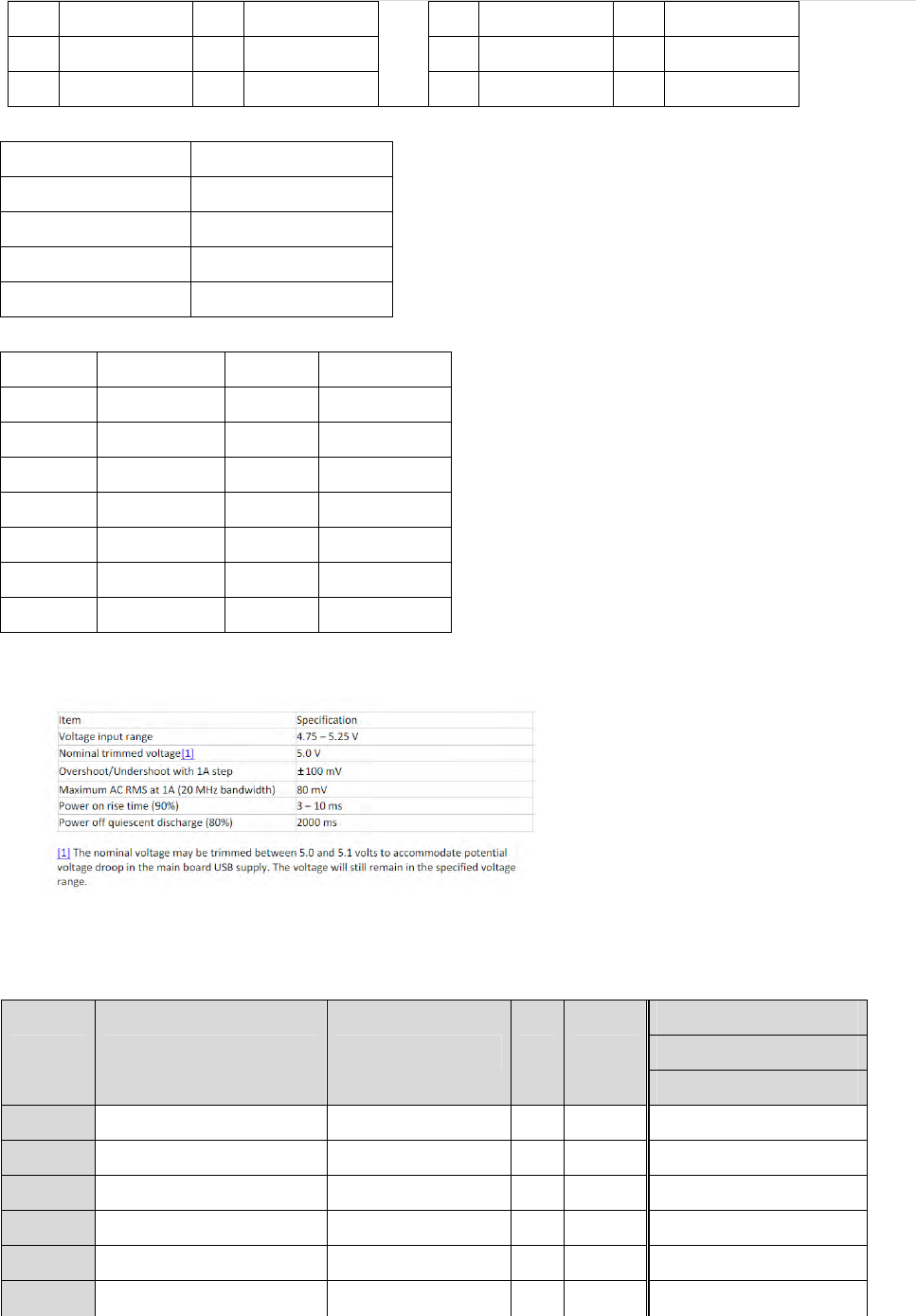
VDD5_IN SPEC:
2-3-3. GPIO Map
Using GPIO of XXXX
XXXXX
Item Function Connect to I/O Active
CPU
1 GPIO_05 I/O
2 GPIO_022 I/O
3 USB2_VBUS_EN O
4 GPIO_08 I/O
5 GPIO_09 I/O
6 GPIO_10 I/O
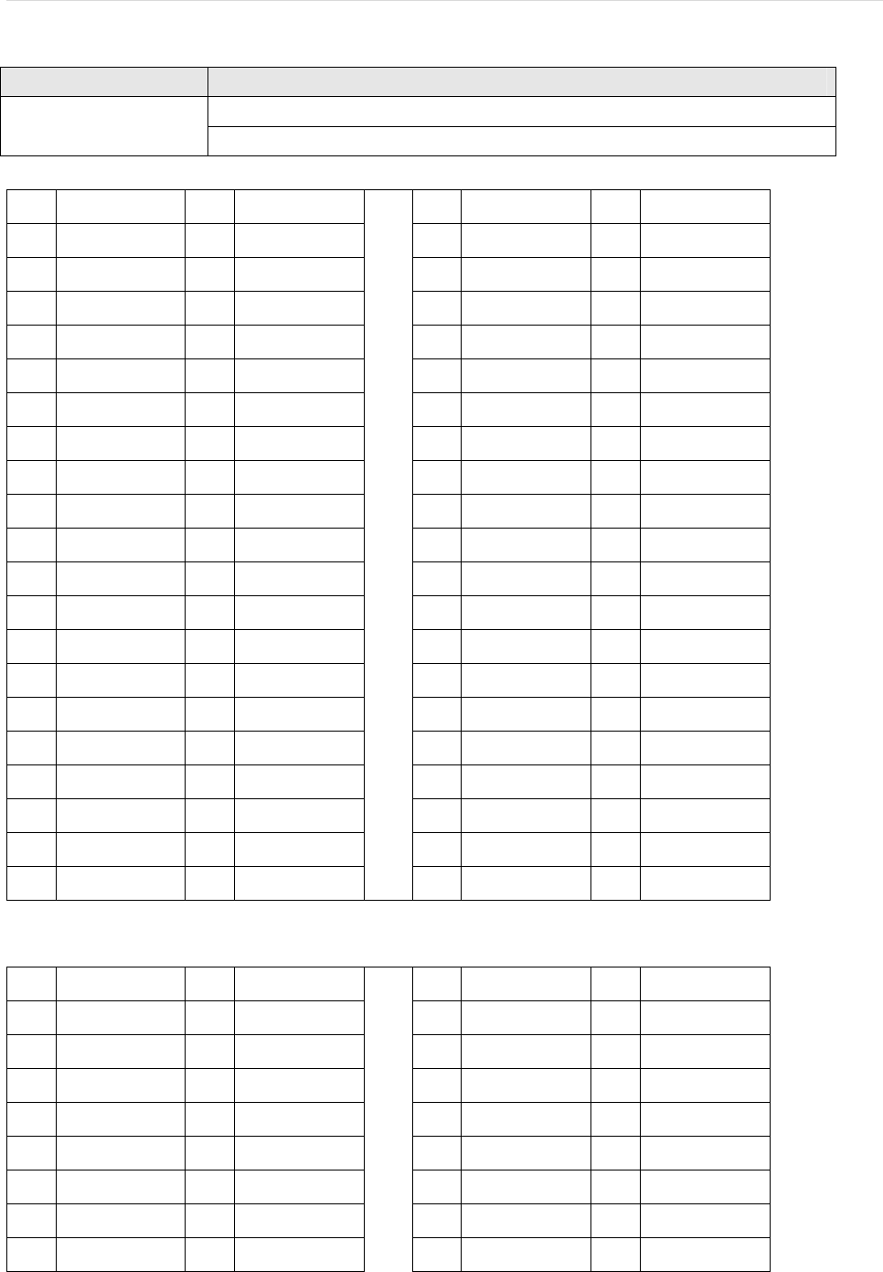
Pin Pin Define Pin Pin Define
1 JTAG_RST 2 GND
3 JTAG_TDI 4 GND
5 JTAG_TDO 6 GND
7 JTAG_TMS 8 GND
9 JTAG_TCK 10 GND
11 SYS_RST_L 12 UART3_TX
13 UART3_RX 14 VDD3_3

AIOS-4.0 Page : 8
Arcadyan Corporation
7 GPIO_11 I/O
8 GPIO_12 I/O
9 GPIO_13 I/O -
10 RF1_GPIO_6 I/O -
11 RF1_BT_GPIO_5 I/O
12 GPIO_14 I/O
13 GPIO_15 I/O
14 GPIO_16 I/O
15 GPIO_17 I/O
16 GPIO_18 I/O
17 GPIO_19 I/O
18 RF2_GPIO_6 I/O
19 GPIO_21 I/O
20 MODULE_TYPE_0 I
21 MODULE_TYPE_1 I
22 MODULE_TYPE_2 I
23 GPIO_04 I/O
24 WL2_REG_ON O
25 MODULE_REV0 I
26 MODULE_REV1 I
27 MODULE_REV2 I
28 GPIO_20 I/O
29 RF1_BT_DEV_WAKE O
30 FACTORY_RESET_BUTTON I
31 GPIO_07 I/O
32 GPIO_24 I/O
33 GPIO_25 I/O
34 GPIO_02 I/O
35 GPIO_06 I/O
36 DSP_DDR_CLK_TERM_EN_L O
37 DSP_VDD_EN_L O
38 DSP_DDR_EN_L O
39 WL1_REG_ON O
40 BT1_REG_ON O
41 AON_GPIO5 I
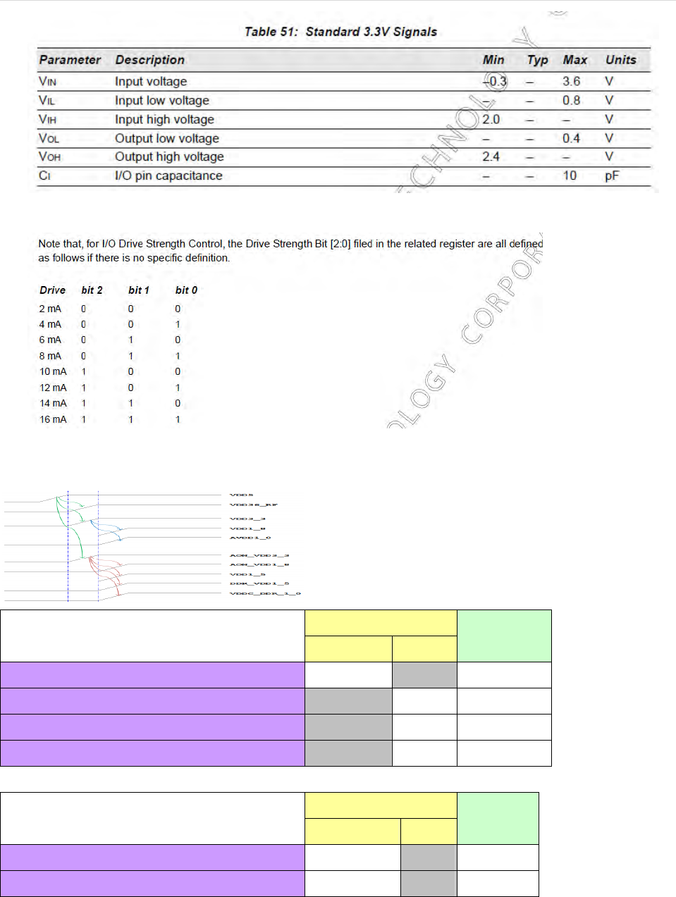
Logic Input high/low Voltage:
AIOS-4.0 Page : 9
Arcadyan Corporation
Drive IO Strength
2-3-4. Power Sequence
Spec
BCM 58305 Power Sequence Spec min(us) max Measurement
Vdd3_3 ramp-up Time 100 - 711.19us
VDDC_DDR_1_0 ramp-up Time - 15ms 671.58us
VDD1_35 ramp-up Time - 15ms 699.80us
DDR_VDD1_35 ramp-up Time - 15ms 716.31us
Spec
BCM 4356 Power Sequence Spec min(us) max Measurement
RF_Vdd3_6 ramp-up Time 40 - 771.95us
RF_dd3_6 up before RF_Vdd3_3 0 - 2.12ms
AIOS-4.0 Page : 10
Arcadyan Corporation
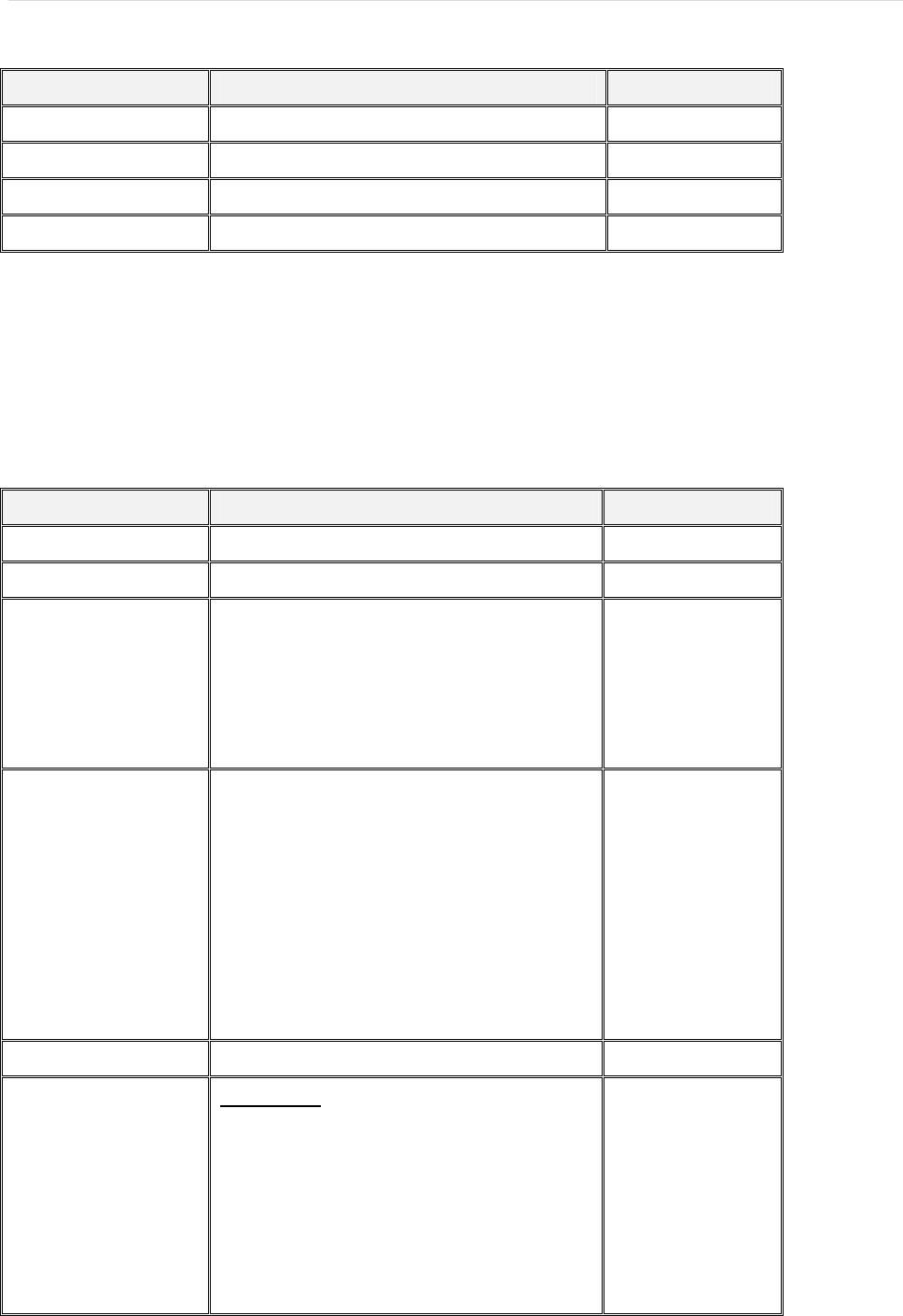
2-3-5. Power Consumption
Status Active
Sleep
echo standby >
/sys/power/state
Deep Sleep
echo mem >
/sys/power/state
Power off
poweroff
Power Irms(mA) Watt(mW) Irms(mA) Watt(mW) Irms(mA) Watt(mW) Irms(mA) Watt(mW)
5V 518.5 2592.5 396.1 1980.5 87 435 15.3 76.5
2-3-6. ESD Transient SPEC
ESD Test SPEC : <1> Contact 4kV
<2> Air 8kV
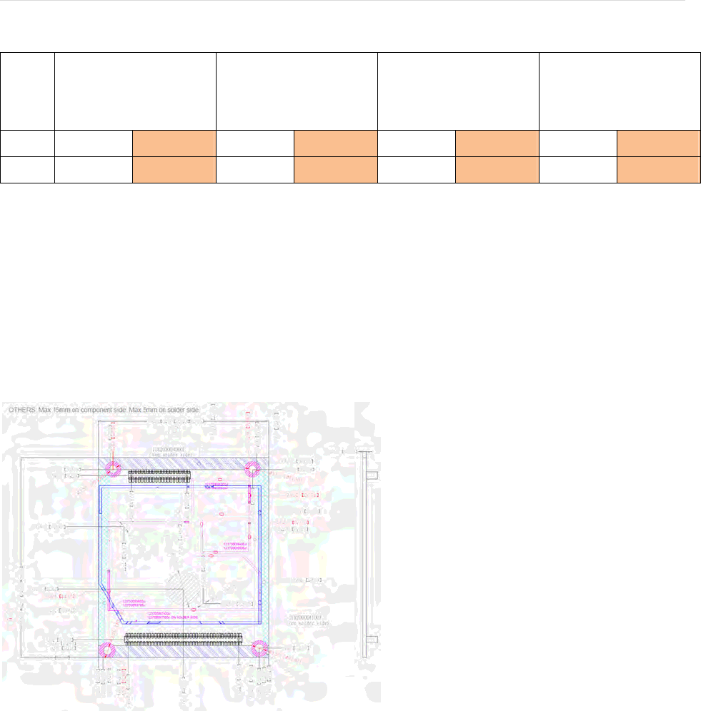
2-3-7. PCB Dimension

AIOS-4.0 Page : 11
Arcadyan Corporation
3. Wireless Specification
There are two radios on module, radio 0 and radio 1. Radio 0 include a dual band (2.4 GHz and 5 GHz) WIFI
and Bluetooth. Radio 1 is only 5 GHz WIFI.
Radio 0 is a Station (STA), it could have soft-AP function. Soft-AP does not use DFS channel. Radio 1 is a
AP.
3-1 Radio 0 specification
Radio 0 include a dual band (2.4 GHz and 5 GHz) WIFI and Bluetooth.
3-1-1 WLAN0 specification
ItemSpecificationRemark
ChipBCM4356
InterfacePCIe
Frequency2400~2483.5MHz(FCC,CE,JP)
2471~2497MHz(JP)
5150~5250MHz(W52,U‐NII‐1,Band1)
5250~5350MHz(W53,U‐NII‐2A,Band2)
5470~5725MHz(W56,U‐NII‐2C,Band3)
5725~5850MHz(W58,U‐NII‐3,Band4)
DFSsupport
DataRateIEEE802.11b:
11,5.5,2,1Mbps
IEEE802.11a
54,48,36,24,18,12,9,6Mbps
IEEE802.11g
54,48,36,24,18,12,9,6Mbps
IEEE802.11nHT20
Upto150Mbps
IEEE802.11nHT40
Upto300Mbps
IEEE802.11acVHT80
Upto886.7Mbps
MIMO2T2R

AIOS-4.0 Page : 12
Arcadyan Corporation
ReceiverSensitivity2.4GHzBand
IEEE802.11b:
‐97dBm@1Mbps
‐88dBm@11Mbps
IEEE802.11g
‐92dBm@6Mbps
‐74dBm@54Mbps
IEEE802.11nHT20
‐90dBm@MCS0
‐71dBm@MCS7
IEEE802.11nHT40
‐87dBm@MCS0
‐68dBm@MCS7
5GHzband
IEEE802.11a
‐91dBm@6Mbps
‐75dBm@54Mbps
IEEE802.11nHT20
‐91dBm@MCS0
‐72dBm@MCS7
IEEE802.11nHT40
‐89dBm@MCS0
‐69dBm@MCS7
IEEE802.11acVHT20
‐91dBm@MCS0
‐72dBm@MCS8
IEEE802.11acVHT40
‐89dBm@MCS0
‐69dBm@MCS9
IEEE802.11acVHT80
‐86dBm@MCS0
‐61dBm@MCS7
AIOS-4.0 Page : 13
Arcadyan Corporation
3-1-2 Bluetooth specification
ItemSpecificationRemark
Chip BCM4356
InterfaceUART
Frequence2400~2483.5MHz
Receivesensitivity‐80dBm
3-2 Radio 1 specification
Radio 1 is only 5 GHz WIFI.
3-2-1 WLAN1 specification
ItemSpecificationRemark
Chip BCM4356
InterfacePCIe
Frequency5150~5250MHz(W52,U‐NII‐1,Band1)
5250~5350MHz(W53,U‐NII‐2A,Band2)
5470~5725MHz(W56,U‐NII‐2C,Band3)
5725~5850MHz(W58,U‐NII‐3,Band4)
DFSsupport
DataRateIEEE802.11a
54,48,36,24,18,12,9,6Mbps
IEEE802.11nHT20
Upto150Mbps
IEEE802.11nHT40
Upto300Mbps
IEEE802.11acVHT80
Upto886.7Mbps
MIMO2T2R
ReceiverSensitivity5GHzband
IEEE802.11a
‐91dBm@6Mbps
‐75dBm@54Mbps
IEEE802.11nHT20
‐91dBm@MCS0
‐72dBm@MCS7

AIOS-4.0 Page : 14
Arcadyan Corporation
IEEE802.11nHT40
‐89dBm@MCS0
‐69dBm@MCS7
IEEE802.11acVHT20
‐91dBm@MCS0
‐72dBm@MCS8
IEEE802.11acVHT40
‐89dBm@MCS0
‐69dBm@MCS9
IEEE802.11acVHT80
‐86dBm@MCS0
‐61dBm@MCS7
FCC & IC Statement:
FCC Statement:
Federal Communication Commission Interference Statement
This equipment has been tested and found to comply with the limits for a Class B digital device, pursuant to
Part 15 of the FCC Rules. These limits are designed to provide reasonable protection against harmful
interference in a residential installation. This equipment generates, uses and can radiate radio frequency
energy and, if not installed and used in accordance with the instructions, may cause harmful interference to
radio communications. However, there is no guarantee that interference will not occur in a particular
installation. If this equipment does cause harmful interference to radio or television reception, which can be
determined by turning the equipment off and on, the user is encouraged to try to correct the interference by
one of the following measures:
● Reorient or relocate the receiving antenna.
● Increase the separation between the equipment and receiver.
● Connect the equipment into an outlet on a circuit different from that to which the receiver is connected.
● Consult the dealer or an experienced radio/TV technician for help.
FCC Caution: Any changes or modifications not expressly approved by the party responsible
for compliance could void the user’s authority to operate this equipment.
This device complies with Part 15 of the FCC Rules. Operation is subject to the following two conditions: (1)
This device may not cause harmful interference, and (2) this device must accept any interference received,
including interference that may cause undesired operation.
For product available in the USA/Canada market, only channel 1~11 can be operated. Selection of other
channels is not possible.

AIOS-4.0 Page : 15
Arcadyan Corporation
This device and it's antennas(s) must not be co-located or operating in conjunction with any other antenna or
transmitter except in accordance with FCC multi-transmitter product procedures.
This device is restricted for indoor use.
IMPORTANT NOTE:
FCC Radiation Exposure Statement:
This equipment complies with FCC radiation exposure limits set forth for an uncontrolled environment. This
equipment should be installed and operated with minimum distance 20 cm between the radiator & your
body.
IC Statement
This device complies with Industry Canada license-exempt RSS standard(s). Operation is subject to the
following two conditions: (1) this device may not cause interference, and (2) this device must accept any
interference, including interference that may cause undesired operation of the device.
Le présent appareil est conforme aux CNR d'Industrie Canada applicables aux appareils radio exempts de
licence. L'exploitation est autorisée aux deux conditions suivantes : (1) l'appareil ne doit pas produire de
brouillage, et (2) l'utilisateur de l'appareil doit accepter tout brouillage radioélectrique subi, même si le
brouillage est susceptible d'en compromettre le fonctionnement.
For product available in the USA/Canada market, only channel 1~11 can be operated. Selection of other
channels is not possible.
Pour les produits disponibles aux États-Unis / Canada du marché, seul le canal 1 à 11 peuvent être
exploités. Sélection d'autres canaux n'est pas possible.
This device and it's antennas(s) must not be co-located or operating in conjunction with any other antenna or
transmitter except in accordance with IC multi-transmitter product procedures.
Cet appareil et son antenne (s) ne doit pas être co-localisés ou fonctionnement en association avec une
autre antenne ou transmetteur.
Dynamic Frequency Selection (DFS) for devices operating in the bands 5250- 5350 MHz,
5470-5600 MHz and 5650-5725 MHz
Sélection dynamique de fréquences (DFS) pour les dispositifs fonctionnant dans les bandes 5250-5350
MHz, 5470-5600 MHz et 5650-5725 MHz

AIOS-4.0 Page : 16
Arcadyan Corporation
The device for operation in the band 5150–5250 MHz is only for indoor use to reduce the potential for
harmful interference to co-channel mobile satellite systems.
les dispositifs fonctionnant dans la bande 5150-5250 MHz sont réservés uniquement pour une
utilisation à l’intérieur afin de réduire les risques de brouillage préjudiciable aux systèmes de satellites
mobiles utilisant les mêmes canaux.
The maximum antenna gain permitted for devices in the bands 5250-5350 MHz and 5470-5725 MHz shall
be such that the equipment still complies with the e.i.r.p. limit.
le gain maximal d’antenne permis pour les dispositifs utilisant les bandes 5250-5350 MHz et
5470-5725 MHz doit se conformer à la limite de p.i.r.e.
The maximum antenna gain permitted for devices in the band 5725-5850 MHz shall be such that the
equipment still complies with the e.i.r.p. limits specified for point-to-point and non-point-to-point operation as
appropriate.
le gain maximal d’antenne permis (pour les dispositifs utilisant la bande 5725-5850 MHz)
doit se conformer à la limite de p.i.r.e. spécifiée pour l’exploitation point à point et non point à point, selon le
cas.
Users should also be advised that high-power radars are allocated as primary users (i.e. priority
users) of the bands 5250-5350 MHz and 5650-5850 MHz and that these radars could cause interference
and/or damage to LE-LAN devices.
De plus, les utilisateurs devraient aussi être avisés que les utilisateurs de radars de haute puissance sont
désignés utilisateurs principaux (c.-à-d., qu’ils ont la priorité) pour les bandes 5250-5350 MHz et 5650-5850
MHz et que ces radars pourraient causer du brouillage et/ou des dommages aux dispositifs LAN-EL.
For indoor use only.
Pour une utilisation en intérieur uniquement.
IMPORTANT NOTE:
IC Radiation Exposure Statement:
This equipment complies with IC RSS-102 radiation exposure limits set forth for an uncontrolled
environment. This equipment should be installed and operated with minimum distance 20 cm between the
radiator & your body.
Cet équipement est conforme aux limites d'exposition aux rayonnements IC établies pour un environnement
non contrôlé. Cet équipement doit être installé et utilisé avec un minimum de 20 cm de distance entre la
source de rayonnement et votre corps.
AIOS-4.0 Page : 17
Arcadyan Corporation
This radio transmitter (IC ID: 4711A-AIOS40F) has been approved by Industry Canada to operate with the
antenna types listed below with the maximum permissible gain and required antenna impedance for each
antenna type indicated. Antenna types not included in this list, having a gain greater than the maximum gain
indicated for that type, are strictly prohibited for use with this device.
Le présent émetteur radio (IC ID: 4711A-AIOS40F) a été approuvé par Industrie Canada pour fonctionner
avec les types d'antenne énumérés ci-dessous et ayant un gain admissible maximal et l'impédance requise
pour chaque type d'antenne. Les types d'antenne non inclus dans cette liste, ou dont le gain est supérieur
au gain maximal indiqué, sont strictement interdits pour l'exploitation de l'émetteur.
Antenna list:
Gain (dBi)
Radio Set Brand P/N Type Connector 2.4GHz 5GHz
1 Airgain N2420DG3-T2L-PK1-G30U PIFA I-PEX 3.10 3.66
2 Airgain N2420DG3-T2L-PK1-G100U PIFA I-PEX 3.10 3.66
3 Airgain N2420DG3-T2L-PK1-G600U PIFA I-PEX 3.10 3.66
4 Airgain N2425D-T2L-PK1-G30U PIFA I-PEX 1.90 3.50
5 Airgain N2425D-T2R-PK1-G150U PIFA I-PEX 1.90 3.50
6 Airgain N2425D-T2R-PK1-G30U PIFA I-PEX 1.90 3.50
R0
7 Airgain N2425D-T2R-PK1-G500U PIFA I-PEX 1.90 3.50
8 Airgain N5X20B-T2L-PK1-G100U PIFA I-PEX - 2.90
R1 9 Airgain N5X20B-T2L-PK1-G600U PIFA I-PEX - 2.90
Gain (dBi)
Radio Set Brand Model No. Type Connector 2.4GHz 5GHz
10 Arcadyan WN9722A-DM Dipole I-PEX 2.94 3.19
11 Arcadyan WN9722A-DM-300mm Dipole I-PEX 2.76 2.63
R0/ R1
12 Arcadyan WN9722A-DM-500mm Dipole I-PEX 1.99 2.59
Note: The EUT has twelve sets of antenna, and each set contains two antennas.