Arcadyan Technology WG4005DARC OfficeConnect Wireless 11g Cable/DSL Router User Manual DUA0055 4AAA01rev01
Arcadyan Technology Corporation OfficeConnect Wireless 11g Cable/DSL Router DUA0055 4AAA01rev01
Contents
- 1. user manual part 1
- 2. user manual part 2
user manual part 1

http://www.3com.com/
Part No. DUA0554-TAAA01
Rev. 01
Published June 2004
OfficeConnect®
11g Cable/DSL Router
User Guide
3CRWE554G72T
3CRWE554G72TU
3Com Corporation
5500 Bayfront Plaza
Santa Clara, California
95052-8145
Copyright © 2003, 3Com Corporation. All rights reserved. No part of this documentation may be reproduced
in any form or by any means or used to make any derivative work (such as translation, transformation, or
adaptation) without written permission from 3Com Corporation.
3Com Corporation reserves the right to revise this documentation and to make changes in content from time
to time without obligation on the part of 3Com Corporation to provide notification of such revision or change.
3Com Corporation provides this documentation without warranty, term, or condition of any kind, either
implied or expressed, including, but not limited to, the implied warranties, terms or conditions of
merchantability, satisfactory quality, and fitness for a particular purpose. 3Com may make improvements or
changes in the product(s) and/or the program(s) described in this documentation at any time.
If there is any software on removable media described in this documentation, it is furnished under a license
agreement included with the product as a separate document, in the hard copy documentation, or on the
removable media in a directory file named LICENSE.TXT or !LICENSE.TXT. If you are unable to locate a copy,
please contact 3Com and a copy will be provided to you.
UNITED STATES GOVERNMENT LEGEND
If you are a United States government agency, then this documentation and the software described herein are
provided to you subject to the following:
All technical data and computer software are commercial in nature and developed solely at private expense.
Software is delivered as “Commercial Computer Software” as defined in DFARS 252.227-7014 (June 1995) or
as a “commercial item” as defined in FAR 2.101(a) and as such is provided with only such rights as are
provided in 3Com’s standard commercial license for the Software. Technical data is provided with limited rights
only as provided in DFAR 252.227-7015 (Nov 1995) or FAR 52.227-14 (June 1987), whichever is applicable.
You agree not to remove or deface any portion of any legend provided on any licensed program or
documentation contained in, or delivered to you in conjunction with, this User Guide.
Unless otherwise indicated, 3Com registered trademarks are registered in the United States and may or may not
be registered in other countries.
3Com, OfficeConnect and the 3Com logo are registered trademarks of 3Com Corporation.
Intel and Pentium are registered trademarks of Intel Corporation. Microsoft, MS-DOS, Windows, and Windows
NT are registered trademarks of Microsoft Corporation. Novell and NetWare are registered trademarks of
Novell, Inc. UNIX is a registered trademark in the United States and other countries, licensed exclusively
through X/Open Company, Ltd.
Netscape Navigator is a registered trademark of Netscape Communications.
JavaScript is a trademark of Sun Microsystems
Wi-Fi and the Wi-Fi logo are registered trademarks of the WI-Fi Alliance.
IEEE and 802 are trademarks of the Institute of Electrical and Electronics Engineers, Inc.
All other company and product names may be trademarks of the respective companies with which they are
associated.
ENVIRONMENTAL STATEMENT
It is the policy of 3Com Corporation to be environmentally-friendly in all operations. To uphold our policy, we
are committed to:
Establishing environmental performance standards that comply with national legislation and regulations.
Conserving energy, materials and natural resources in all operations.
Reducing the waste generated by all operations. Ensuring that all waste conforms to recognized environmental
standards. Maximizing the recyclable and reusable content of all products.
Ensuring that all products can be recycled, reused and disposed of safely.
Ensuring that all products are labelled according to recognized environmental standards.
Improving our environmental record on a continual basis.
End of Life Statement
3Com processes allow for the recovery, reclamation and safe disposal of all end-of-life electronic components.
Regulated Materials Statement
3Com products do not contain any hazardous or ozone-depleting material.
Environmental Statement about the Documentation
The documentation for this product is printed on paper that comes from sustainable, managed forests; it is
fully biodegradable and recyclable, and is completely chlorine-free. The varnish is environmentally-friendly, and
the inks are vegetable-based with a low heavy-metal content.

CONTENTS
ABOUT THIS GUIDE
Naming Convention 7
Conventions 8
Feedback about this User Guide 8
Related Documentation 9
Product Registration 9
1INTRODUCING THE ROUTER
OfficeConnect 11g Cable/DSL Router 11
Router Advantages 13
Package Contents 13
Minimum System and Component Requirements 14
Front Panel 14
Rear Panel 16
2HARDWARE INSTALLATION
Introduction 19
Safety Information 19
Positioning the Router 19
Using the Rubber Feet 20
Wall Mounting 20
Before you Install your Router 21
Powering Up the Router 22
Connecting the Router 22
3SETTING UP YOUR COMPUTERS
Obtaining an IP Address Automatically 25
Windows 2000 25
Windows XP 27
Windows 95/98/ME 27

Macintosh 27
Disabling PPPoE and PPTP Client Software 28
Disabling Web Proxy 28
4RUNNING THE SETUP WIZARD
Accessing the Wizard 29
Password 32
Time Zone 32
WAN Settings 33
LAN Settings 38
DHCP 38
Wireless Settings 39
Summary 40
5ROUTER CONFIGURATION
Navigating Through the Router Configuration Pages 41
Main Menu 41
Option Tabs 42
Welcome Screen 42
Notice Board 42
Password 43
Wizard 44
LAN Settings 44
Unit Configuration 44
DHCP Clients List 45
Wireless Settings 47
Configuration 47
Encryption 49
Configuring WPA Encryption 49
Configuring WEP Encryption 50
Connection Control 53
Client List 55
Profile 55
Internet Settings 57
Connection to ISP 58
Firewall 63
Virtual Servers 63

Special Applications 65
PC Privileges 67
URL Filter 69
Security 73
System Tools 75
Restart 75
Time Zone 76
Configuration 77
Upgrade 78
Status and Logs 78
Status 78
Usage 79
Logs 80
Support/Feedback 80
Support 81
Feedback 81
6TROUBLESHOOTING
Basic Connection Checks 83
Browsing to the Router Configuration Screens 83
Connecting to the Internet 84
Forgotten Password and Reset to Factory Defaults 85
Wireless Networking 85
Replacement Power Adapters 87
Alert LED 88
Recovering from Corrupted Software 88
Frequently Asked Questions 89
AUSING DISCOVERY
Running the Discovery Application 91
Windows Installation (95/98/2000/Me/NT) 91
BIP ADDRESSING
The Internet Protocol Suite 93
Managing the Router over the Network 93
IP Addresses and Subnet Masks 93

How does a Device Obtain an IP Address and Subnet Mask? 95
DHCP Addressing 95
Static Addressing 95
Auto-IP Addressing 95
CTECHNICAL SPECIFICATIONS
Standards 98
DSAFETY INFORMATION
EEND USER SOFTWARE LICENSE AGREEMENT
FISP INFORMATION
GLOSSARY
INDEX
REGULATORY NOTICES FOR THE 11G CABLE/DSL ROUTER

ABOUT THIS GUIDE
This guide describes how to install and configure the OfficeConnect 11g
Cable/DSL Router (3CRWE554G72T and 3CRWE554G72TU).
This guide is intended for use by those responsible for installing and
setting up network equipment; consequently, it assumes a basic working
knowledge of LANs (Local Area Networks) and Internet Router systems.
If a release note is shipped with the OfficeConnect 11g Cable/DSL Router
and contains information that differs from the information in this guide,
follow the information in the release note.
Most user guides and release notes are available in Adobe Acrobat
Reader Portable Document Format (PDF) on the 3Com World Wide Web
site:
http://www.3com.com
Naming Convention Throughout this guide, the OfficeConnect 11g Cable/DSL Router is
referred to as the “Router”.
Category 3 and Category 5 Twisted Pair Cables are referred to as Twisted
Pair Cables throughout this guide.
8ABOUT THIS GUIDE
Conventions Table 1 and Ta b l e 2 list conventions that are used throughout this guide.
Feedback about this
User Guide
Your suggestions are very important to us. They will help make our
documentation more useful to you. Please e-mail comments about this
document to 3Com at:
pddtechpubs_comments@3com.com
Please include the following information when commenting:
■Document title
■Document part number (on the title page)
■Page number (if appropriate)
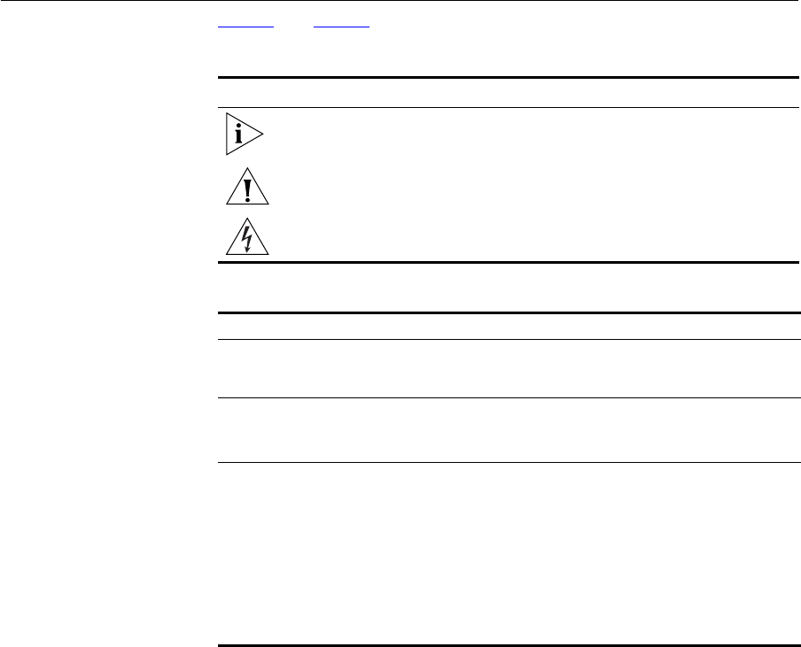
Table 1 Notice Icons
Icon Notice Type Description
Information note Information that describes important features or
instructions.
Caution Information that alerts you to potential loss of data or
potential damage to an application, system, or device.
Warning Information that alerts you to potential personal
injury.
Table 2 Text Conventions
Convention Description
The words “enter”
and “type”
When you see the word “enter” in this guide, you must type
something, and then press Return or Enter. Do not press
Return or Enter when an instruction simply says “type.”
Keyboard key names If you must press two or more keys simultaneously, the key
names are linked with a plus sign (+). Example:
Press Ctrl+Alt+Del
Words in italics Italics are used to:
■Emphasize a point.
■Denote a new term at the place where it is defined in the
text.
■Identify menu names, menu commands, and software
button names. Examples:
From the Help menu, select Contents.
Click OK.

Conventions 9
Example:
■OfficeConnect 11g Cable/DSL Router User Guide
■Part Number DUA0554-TAAA01
■Page 24
Do not use this e-mail address for technical support questions. For
information about contacting Technical Support, please refer to the
Support and Safety Information sheet.
Related
Documentation
In addition to this guide, each Router document set includes one
Installation Guide. This guide contains the instructions you need to install
and configure your Router.
Product Registration You can now register your Router on the 3Com web site and receive
up-to-date information on your product:
http://www.3com.com/register/
10 ABOUT THIS GUIDE

1INTRODUCING THE ROUTER
Welcome to the world of networking with 3Com®. In the modern
business environment, communication and sharing information is crucial.
Computer networks have proved to be one of the fastest modes of
communication but, until recently, only large businesses could afford the
networking advantage. The OfficeConnect® product range from 3Com
has changed all this, bringing networks to the small office.
The products that compose the OfficeConnect range give you, the small
office user, the same power, flexibility, and protection that has been
available only to large corporations. Now, you can network the
computers in your office, connect them all to a single Internet outlet, and
harness the combined power of all of your computers.
OfficeConnect 11g
Cable/DSL Router
The OfficeConnect 11g Cable/DSL Router is designed to provide a
cost-effective means of sharing a single broadband Internet connection
amongst several wired and wireless computers. The Router also provides
protection in the form of an electronic “firewall” preventing anyone
outside of your network from seeing your files or damaging your
computers. The Router can also prevent your users from accessing Web
sites which you find unsuitable.
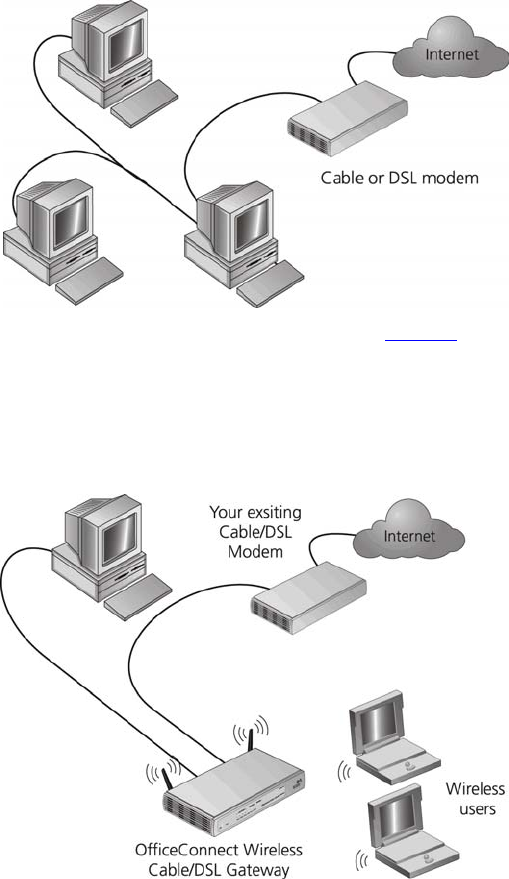
Figure 1 shows an example network without a Router. In this network,
only one computer is connected to the Internet. This computer must
always be powered on for the other computers on the network to access
the Internet.
12 CHAPTER 1: INTRODUCING THE ROUTER
Figure 1 Example Network Without a Router
When you use the Router in your network (Figure 2), it becomes your
connection to the Internet. Connections can be made directly to the
Router, or to an OfficeConnect Switch or Hub, expanding the number of
computers you can have in your network.
Figure 2 Example Network Using a Cable/DSL Router

Router Advantages 13
Router Advantages The advantages of the Router include:
■Shared Internet connection for both wired and wireless computers
■High speed 802.11g wireless networking
■No need for a dedicated, “always on” computer serving as your
Internet connection
■Cross-platform operation for compatibility with Windows, Unix and
Macintosh computers
■Easy-to-use, Web-based setup and configuration
■Provides centralization of all network address settings (DHCP)
■Acts as a Virtual server to enable remote access to Web, FTP, and other
services on your network
■Security — Firewall protection against Internet hacker attacks and
encryption to protect wireless network traffic
■Filtered access of inappropriate Web sites using the built-in URL filter
Package Contents The Router kit includes the following items:
■One OfficeConnect 11g Cable/DSL Router
■One power adapter for use with the Router
■Four rubber feet
■One Ethernet cable
■One CD-ROM containing the Router Discovery program and this User
Guide
■Installation Guide
■One Support and Safety Information Sheet
■One Warranty Flyer
If any of these items are missing or damaged, please contact your retailer.
14 CHAPTER 1: INTRODUCING THE ROUTER
Minimum System
and Component
Requirements
Your Router requires that the computer(s) and components in your
network be configured with at least the following:
■A computer with an operating system that supports TCP/IP
networking protocols (for example Windows 95/98/NT/Me/2000/XP,
Unix, Mac OS 8.5 or higher).
■An Ethernet 10Mbps or 10/100 Mbps NIC for each computer to be
connected to the four-port switch on your Router.
■An 802.11b or 802.11g wireless NIC.
■A cable modem or DSL modem with an Ethernet port (RJ-45
connector).
■An active Internet access account.
■A Web browser that supports JavaScript, such as Netscape 4.7 or
higher, Internet Explorer 5.0 or higher, or Mozilla 1.2.1 or higher.
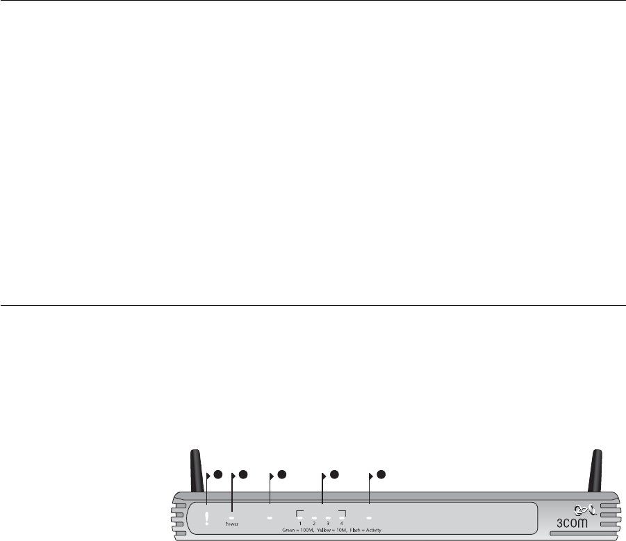
Front Panel The front panel of the Router contains a series of indicator lights (LEDs)
that help describe the state of various networking and connection
operations.
Figure 3 Router - Front Panel
1 Alert LED
Orange
Indicates a number of different conditions, as described below.
Off - The Router is operating normally.
Flashing quickly - Indicates one of the following conditions:
■The Router has just been started up and is running a self-test routine,
or
21 43
OfficeConnect Wireless 11g Cable/DSL Gateway
3CRWE554G72
LAN Status Cable/DSL
5
WLAN
Alert Enabled

Front Panel 15
■The administrator has invoked the Reset to Factory Defaults
command, or
■The system software is in the process of being upgraded
In each of these cases, wait until the Router has completed the current
operation and the alert LED is Off.
Flashing slowly - The Router has completed the Reset to Factory Defaults
process, and is waiting for you to reset the unit. To do this, remove
power, wait 10 seconds and then re-apply power. The Router will then
enter the start-up sequence and resume normal operation.
If you have used a cable to reset the unit to Factory Defaults, follow steps
5 to 7 in “Forgotten Password and Reset to Factory Defaults” on
page 85.
On for 2 seconds, and then off - The Router has detected and prevented
a hacker from attacking your network from the Internet.
Continuously on - A fault has been detected with your Router during the
start-up process. Refer to Chapter 6 “Troubleshooting”.
2Power LED
Green
Indicates that the Router is powered on.
3 Wireless LAN (WLAN) Status LED
Yellow
If the LED is on it indicates that wireless networking is enabled. If the LED
is flashing, data is being transmitted or received. If the LED is off, the
Wireless LAN has been disabled in the Router, or there is a problem. Refer
to Chapter 6 “Troubleshooting”.
4 Four LAN Status LEDs
Green (100Mbps link) / yellow (10Mbps link)
If the LED is on, the link between the port and the next piece of network
equipment is OK. If the LED is flashing, the link is OK and data is being
transmitted or received. If the LED is off, nothing is connected, the
connected device is switched off, or there is a problem with the
connection (refer to Chapter 6 “Troubleshooting”). The port will
automatically adjust to the correct speed and duplex.
16 CHAPTER 1: INTRODUCING THE ROUTER
5 Cable/DSL Status LED
Green (100Mbps link) / yellow (10Mbps link)
If the LED is on, the link between the Router and the cable or DSL modem
is OK. If the LED is flashing, the link is OK and data is being transmitted or
received. If the LED is off, nothing is connected, the modem is switched
off or there is a problem (refer to Chapter 6 “Troubleshooting”).
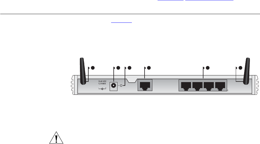
Rear Panel The rear panel (Figure 4) of the Router contains four LAN ports, one
Ethernet Cable/DSL port, a power adapter OK LED, and a power adapter
socket.
Figure 4 Router - Rear Panel
6 Wireless Antennae
The antennae on the product should be placed in a ‘V’ position when
initially installed.
CAUTION: Do not force the antennae beyond their mechanical stops.
Rotating the antennae further may cause damage.
7 Power Adapter Socket
Only use the power adapter supplied with this Router. Do not use any
other adapter.
8 Power Adapter OK LED
Green
Indicates that the power adapter is supplying power to the Router. If the
LED is off, there may be a problem with the power adapter or adapter
cable.
9 Ethernet Cable/DSL port
Use the supplied patch cable to connect the Router to the Ethernet port
on your cable or DSL modem. The port will automatically adjust to the
correct speed and duplex, and will set itself to MDI or MDIX depending
on the device to which they are connected and the type of cable used.
7 9 108
4
Ethernet
Cable/
DSL
OK
6 6
LAN
Rear Panel 17
10 Four 10/100 LAN ports
Using suitable RJ-45 cable, you can connect your Router to a computer,
or to any other piece of equipment that has an Ethernet connection (for
example, a hub or a switch). The LAN ports will automatically set
themselves to MDI or MDIX depending on the device to which they are
connected and the type of cable used.
18 CHAPTER 1: INTRODUCING THE ROUTER

2HARDWARE INSTALLATION
Introduction This chapter will guide you through a basic installation of the Router,
including:
■Connecting the Router to the Internet.
■Connecting the Router to your network.
■Setting up your computers for networking with the Router.
Safety Information
WARNING: Please read the “Safety Information” section in Appendix D
before you start.
VORSICHT: Bitte lesen Sie den Abschnitt “Wichtige Sicherheitshinweise”
sorgfältig durch, bevor Sie das Gerät einschalten.
AVERTISSEMENT: Veuillez lire attentivement la section “Consignes
importantes de sécurité” avant de mettre en route.
Positioning the
Router
You should place the Router in a location that:
■is conveniently located for connection to the cable or DSL modem that
will be used to connect to the Internet.
■is centrally located to the wireless computers that will connect to the
Router. A suitable location might be on top of a high shelf or similar
furniture to optimize wireless connections to computers in both
horizontal and vertical directions, allowing wider coverage.
■allows convenient connection to the computers that will be connected
to the four LAN ports on the rear panel, if desired.
■allows easy viewing of the front panel LED indicator lights, and access
to the rear panel connectors, if necessary.

20 CHAPTER 2: HARDWARE INSTALLATION
When positioning your Router, ensure:
■It is out of direct sunlight and away from sources of heat.
■Cabling is away from power lines, fluorescent lighting fixtures, and
sources of electrical noise such as radios, transmitters and broadband
amplifiers.
■Water or moisture cannot enter the case of the unit.
■Air flow around the unit and through the vents in the side of the case
is not restricted. 3Com recommends you provide a minimum of
25 mm (1 in.) clearance.
Using the Rubber
Feet
Use the four self-adhesive rubber feet to prevent your Router from
moving around on your desk or when stacking with other flat top
OfficeConnect units. Only stick the feet to the marked areas at each
corner of the underside of your Router.
Wall Mounting There are two slots on the underside of the Router that can be used for
wall mounting.
When wall mounting the unit, ensure that it is within reach of the power
outlet.
You will need two suitable screws to wall mount the unit. To do this:
1Ensure that the wall you use is smooth, flat, dry and sturdy and make two
screw holes which are 150 mm (5.9 in.) apart.
2Fix the screws into the wall, leaving their heads 3 mm (0.12 in.) clear of
the wall surface.
3Remove any connections to the unit and locate it over the screw heads.
When in line, gently push the unit on to the wall and move it downwards
to secure.
When making connections, be careful not to push the unit up and off the
wall.
CAUTION: Only wall mount single units, do not wall mount stacked
units.
Before you Install your Router 21
Before you Install
your Router
Before you install and configure your Router, you need the following
additional information. If you do not have this information, contact your
Internet Service Provider (ISP). Space is provided below for you to record
this information.
If you have a DSL connection and your ISP allocates IP information
dynamically over PPPoE, you need a User Name and Password:
If you have a DSL connection and your ISP allocates IP information
dynamically over PPTP, you need a User Name, Password and PPTP Server
Address:
You only need a PPPoE Service Name if your ISP requires one. Do not
enter anything if your ISP does not require this information.
If your ISP allocates fixed or static IP information, you need the following
information:
PPPoE User Name : ______________________
PPPoE Password : ______________________
PPPoE Service Name : ______________________
PPTP User Name : ______________________
PPTP Password : ______________________
PPTP Server Address : ____.____.____.____
IP Address : ____.____.____.____
Subnet Mask : ____.____.____.____
Default Router address : ____.____.____.____
DNS address : ____.____.____.____
22 CHAPTER 2: HARDWARE INSTALLATION
If your ISP allocates IP information dynamically over a protocol other than
PPPoE, you do not need any further information. This configuration is
typical of cable connections.
Powering Up the
Router
To power up the Router:
1Plug the power adapter into the power adapter socket located on the
back panel of the Router.
2Plug the power adapter into a standard electrical wall socket.
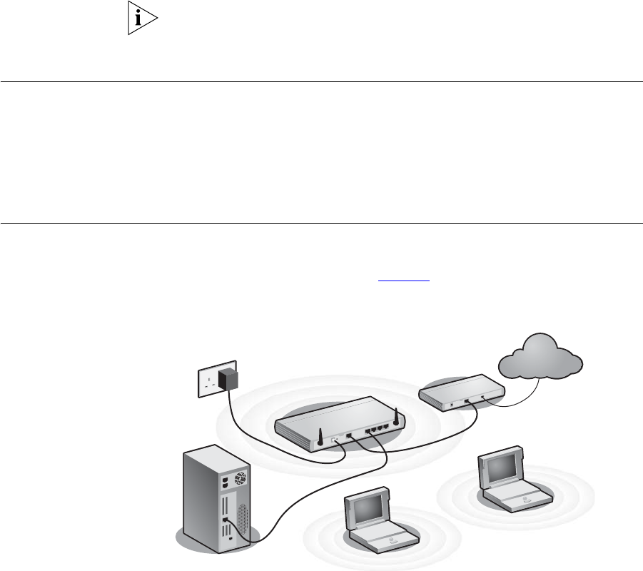
Connecting the
Router
The first step for installing your Router is to physically connect it to a
cable or DSL modem and then connect it to a computer in order to be
able to access the Internet. See Figure 5:
Figure 5 Connecting the Router
To use your Router to connect to the Internet through an external cable
or DSL modem:
1Insert one end of the supplied Ethernet (RJ-45 Category 5) cable into the
Cable/DSL port on the rear panel of the Router.
2Insert the other end of the cable into the RJ-45 port on your cable or DSL
modem. Check that the Cable/DSL status LED lights on the Router.
3Connect the cable or DSL modem to the Internet.
Internet
Your existing
Cable/DSL Modem
Power
Supply Unit
Your PC
Wireless
Users
3Com OfficeConnect
Wireless 11g Cable/DSL
Gateway
Connecting the Router 23
4Connect your computer to one of the four LAN ports on the Router using
a twisted pair cable. Check that the corresponding LAN status LED on the
Router lights.
You have now completed the hardware installation of your Router. Next
you need to set up your computers so that they can make use of the
Router to communicate with the Internet.
3Com recommends that you perform the initial Router configuration
from a computer that is directly connected to one of the LAN ports.
If you configure the Router from a wireless computer, note that you may
lose contact with the Router if you change the wireless configuration.
To communicate wirelessly with your Router, your wireless NIC should be
set as follows:
■Encryption — none
■Service Area Name/SSID — 3Com
■Channel — 11
24 CHAPTER 2: HARDWARE INSTALLATION

3SETTING UP YOUR COMPUTERS
The Router has the ability to dynamically allocate network addresses to
the computers on your network, using DHCP. However, your computers
need to be configured correctly for this to take place. To change the
configuration of your computers to allow this, follow the instructions in
this chapter. If your computers are configured with fixed or static
addresses and you do not wish to change this, then you should use the
Discovery program on the Router CD-ROM to detect and configure your
Router. Refer to Appendix A for information on using the Discovery
program.
Obtaining an IP
Address
Automatically
Windows 2000 If you are using a Windows 2000-based computer, use the following
procedure to change your TCP/IP settings:
1From the Windows Start Menu, select Settings > Control Panel.
2Double click on Network and Dial-Up Connections.
3Double click on Local Area Connection.
4Click on Properties.
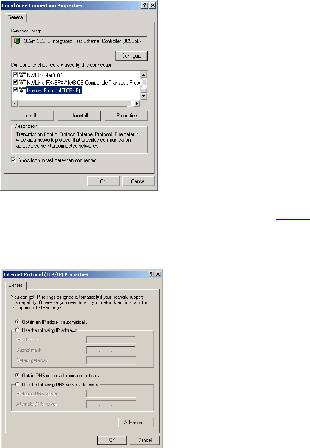
5A screen similar to Figure 6 should be displayed. Select Internet Protocol
TCP/IP and click on Properties.
26 CHAPTER 3: SETTING UP YOUR COMPUTERS
Figure 6 Local Area Properties Screen
6Ensure that the options Obtain an IP Address automatically, and Obtain
DNS server address automatically are both selected as shown in Figure 7.
Click OK.
Figure 7 Internet Protocol (TCP/IP) Properties Screen
7Restart your computer.
Obtaining an IP Address Automatically 27
Windows XP
1From the Windows Start menu, select Control Panel.
2Click on Network and Internet Connections.
3Click on the Network Connections icon.
4Double click on LAN or High Speed Connection icon. A screen titled Local
Area Connection Status will appear.
5Select Internet Protocol TCP/IP and click on Properties.
6Ensure that the options Obtain an IP Address automatically, and Obtain
DNS servers automatically are both selected. Click OK.
7Restart your computer.
Windows 95/98/ME
1From the Windows Start Menu, select Settings > Control Panel.
2Double click on Network. Select the TCP/IP item for your network card
and click on Properties.
3In the TCP/IP dialog, select the IP Address tab, and ensure that Obtain IP
address automatically is selected. Click OK.
Macintosh If you are using a Macintosh computer, use the following procedure to
change your TCP/IP settings:
1From the desktop, select Apple Menu, Control Panels, and TCP/IP.
2In the TCP/IP control panel, set Connect Via: to “Ethernet”.
3In the TCP/IP control panel, set Configure: to “Using DHCP Server.”
4Close the TCP/IP dialog box, and save your changes.
5Restart your computer.
28 CHAPTER 3: SETTING UP YOUR COMPUTERS
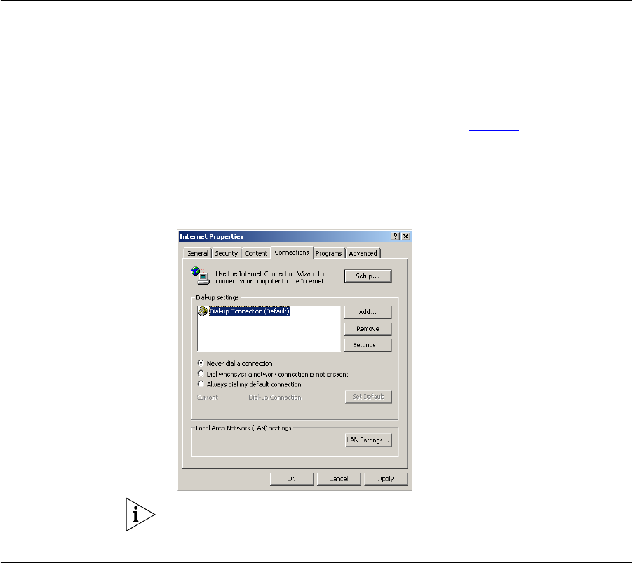
Disabling PPPoE
and PPTP Client
Software
If you have PPPoE or PPTP client software installed on your computer, you
will need to disable it. To do this:
1From the Windows Start menu, select Settings > Control Panel.
2Double click on Internet Options.
3Select the Connections Tab. A screen similar to Figure 8 should be
displayed.
4Select the Never Dial a Connection option.
Figure 8 Internet Properties Screen
You may wish to remove the PPPoE client software from your computer
to free resources, as it is not required for use with the Router.
Disabling Web
Proxy
Ensure that you do not have a web proxy enabled on your computer.
Go to the Control Panel and click on Internet Options. Select the
Connections tab and click LAN Settings at the bottom. Make sure that
the Use Proxy Server option is unchecked.
4RUNNING THE SETUP WIZARD
Accessing the
Wizard
The Router setup program is Web-based, which means that it is accessed
through your Web browser (Netscape Navigator 4.7 or higher, Internet
Explorer 5.0 or higher, or Mozilla 1.2.1 or higher).
To use the Setup Wizard:
1Ensure that you have at least one computer connected to the Router.
Refer to Chapter 2 for details on how to do this.
2Launch your Web browser on the computer.
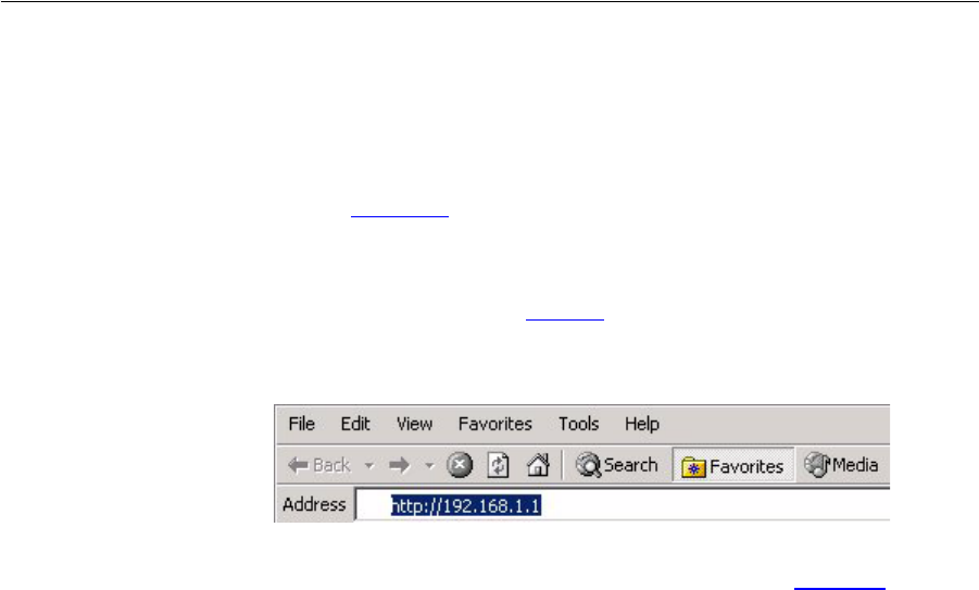
3Enter the following URL in the location or address field of your browser:
http://192.168.1.1 (Figure 9). The Login screen displays.
Figure 9 Web Browser Location Field (Factory Default)
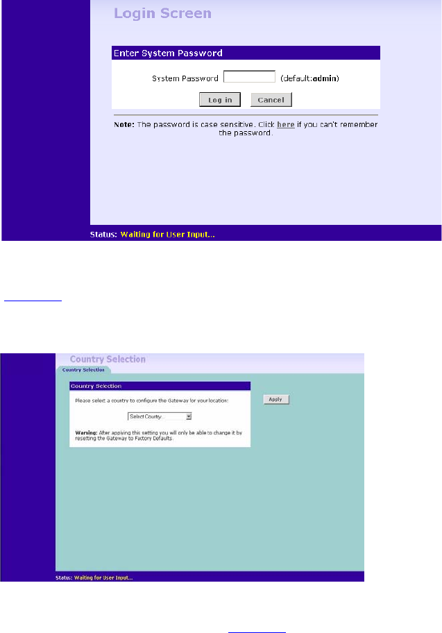
4To log in as an administrator, enter the password (the default setting is
admin) in the System Password field and click Log in (Figure 10).
30 CHAPTER 4: RUNNING THE SETUP WIZARD
Figure 10 Router Login Screen
5If the password is correct, the Country Selection screen will appear. Select
the country you wish to configure the Router for, then click Apply.
(Figure 11)
Figure 11 Country Selection Screen
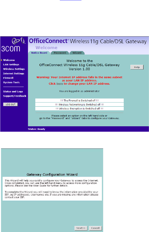
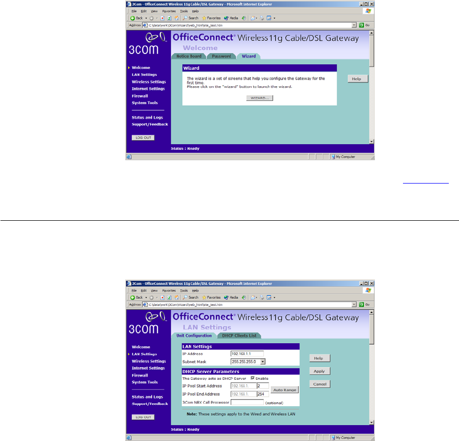
6When you have selected a country either:
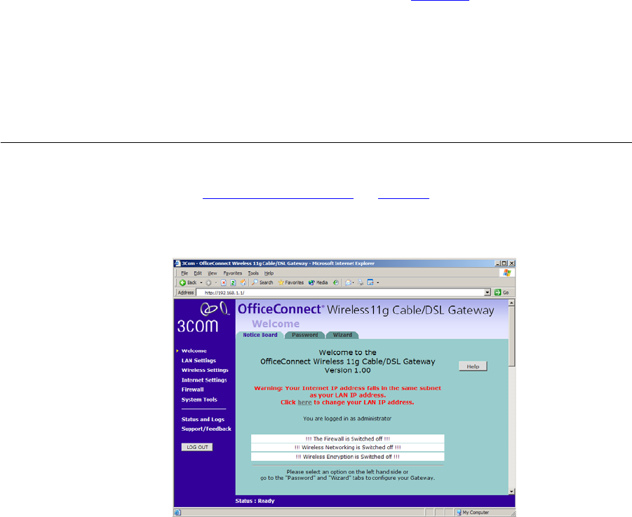
■The Welcome screen will appear (Figure 12). Select the Wizard tab
and click Wizard.
or
32 CHAPTER 4: RUNNING THE SETUP WIZARD
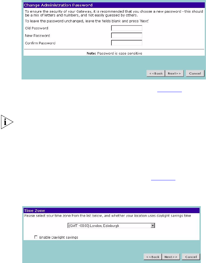
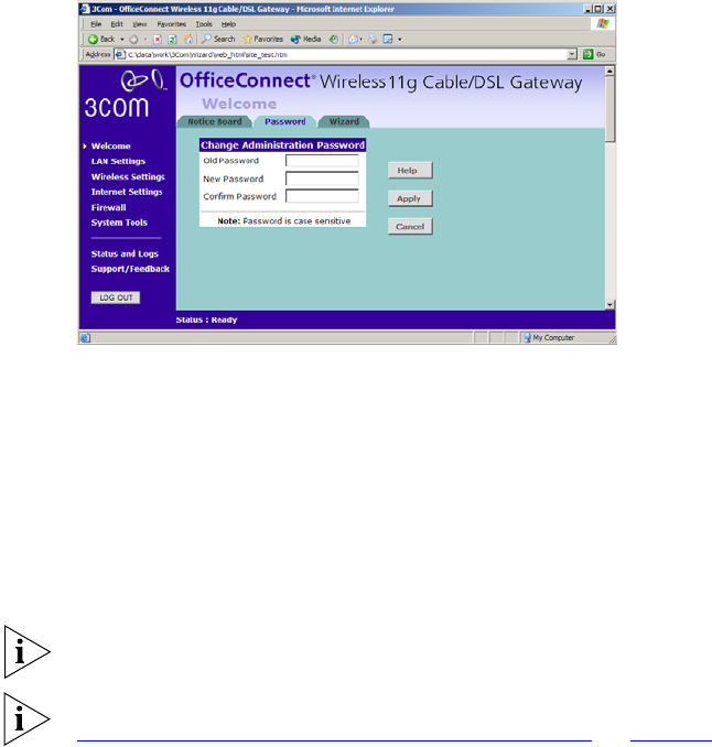
Password Figure 14 Change Administration Password Screen
When the Change Administration Password screen (Figure 14) appears,
type the Old Password, then a new password in both the New Password
and Confirm Password boxes.
3Com recommends entering a new password when setting up the Router
for the first time. The Router is shipped from the factory with a default
password, admin.
1. Password is case sensitive.
2. Write the new password down and keep it in a safe place, so that you
can change your settings in the future.
Click Next to display the Time Zone setup screen (Figure 15).
Time Zone Figure 15 Time Zone Screen
Select your time zone from the pull-down menu, check the daylight
savings option if required, and then click Next.
Accessing the Wizard 33
The Daylight Savings option advances the system clock by one hour. It
does not cause the system clock to be updated for daylight savings time
automatically.
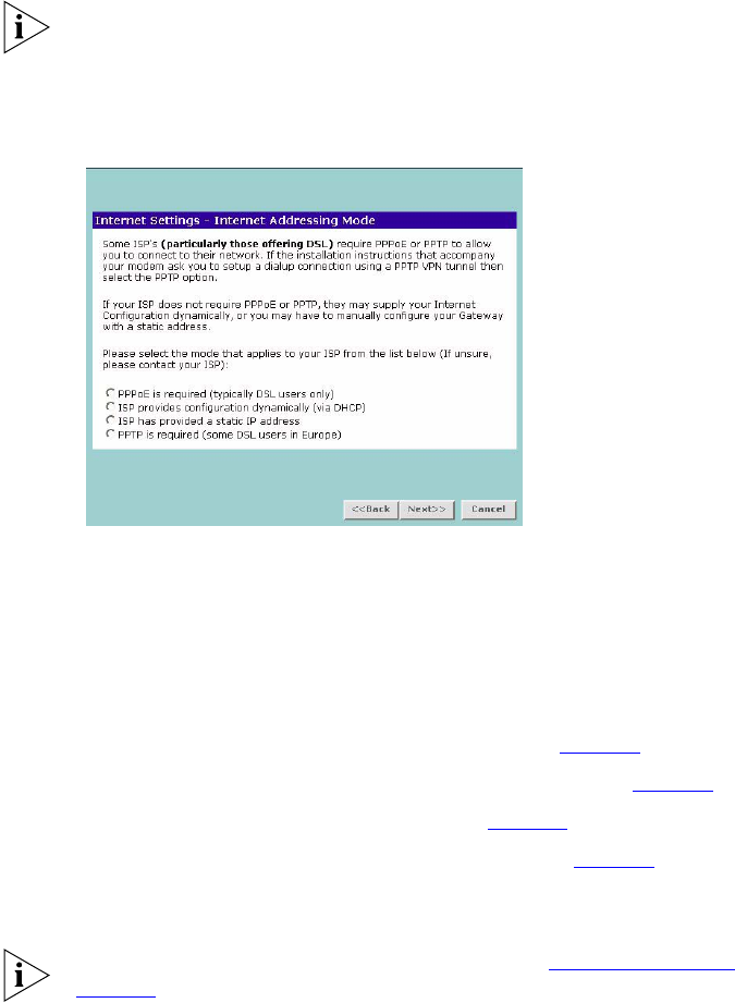
WAN Settings Figure 16 Internet Settings Screen
This Internet Addressing Mode window allows you to set up the Router
for the type of Internet connection you have. Before setting up your
Internet connection mode, have the modem setting information from
your ISP ready.
Select an Internet Addressing mode from the following:
■PPPoE is required (typically DSL users only) see page 34
■ISP provides configuration dynamically (via DHCP) see page 35
■ISP has provided a static IP address see page 36
■PPTP is required (some DSL users in Europe) see page 37
and click Next.
For further information on selecting a mode see “Internet Settings” on
page 57.
34 CHAPTER 4: RUNNING THE SETUP WIZARD
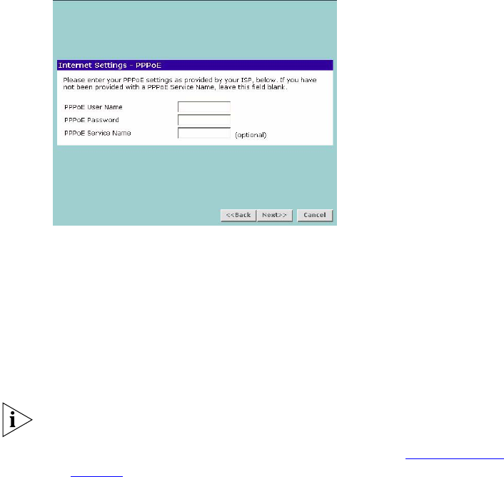
PPPoE Mode
Figure 17 PPPoE Screen
To setup the Router for use with a PPP over Ethernet (PPPoE) connection,
use the following procedure:
1Enter your PPP over Ethernet user name in the PPPoE User Name text box.
2Enter your PPP over Ethernet password in the PPPoE Password text box.
3Enter your PPP over Ethernet service name in the PPPoE Service Name text
box.
This is optional. Not all ISPs require a PPPoE service name.
Do not enter anything in this box if your ISP does not require a service
name.
4Check all of your settings, and then click Next. Refer to “LAN Settings”
on page 38 for more information.
Accessing the Wizard 35
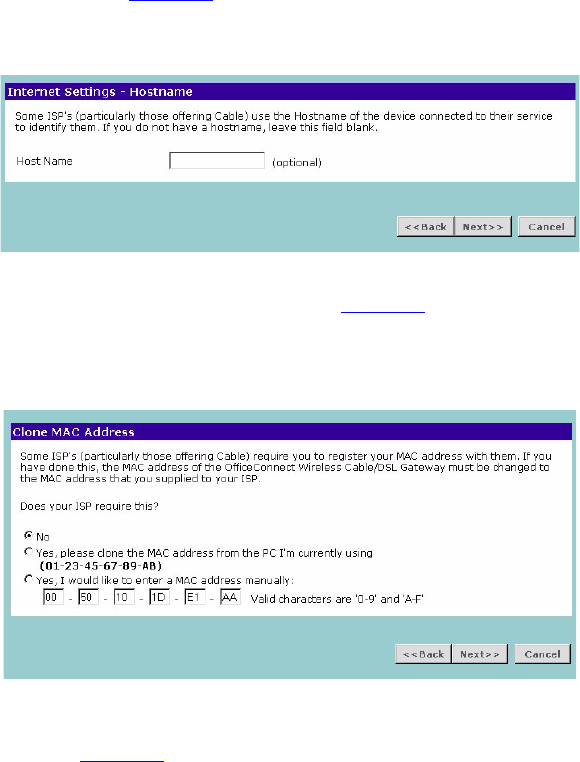
Dynamic IP Address Mode
To setup the Router for use with a dynamic IP address connection:
1Select the ISP provides configuration dynamically (via DHCP) and then
click Next. See Figure 16.
Figure 18 Hostname Screen
2Some ISPs require a host name. If your ISP has this requirement, enter the
host name in the Host Name text box (Figure 18) and click Next. The
Clone MAC Address screen displays.
Figure 19 Clone MAC Address Screen
3If your ISP requires an assigned MAC address, select Yes, I would like to
enter a MAC address manually and enter the values for a MAC address if
required (Figure 19). If the computer you are now using is the one that
was previously connected directly to the cable modem, choose Yes,
please clone the MAC address from the PC I’m currently using.
36 CHAPTER 4: RUNNING THE SETUP WIZARD
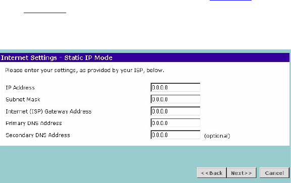
Static IP Mode
To setup the Router for use with a static IP address connection, use the
following procedure:
1Select ISP has provided a static IP address, (see Figure 16) and then click
Next. Figure 20 displays.
Figure 20 Static IP Mode Screen
2Enter your IP Address in the IP Address text box.
3Enter your subnet mask in the Subnet Mask text box.
4Enter your ISP Router address in the Internet (ISP) Router Address text
box.
5Enter your primary DNS address in the Primary DNS Address text box.
6Enter your secondary DNS address in the Secondary DNS Address text
box.
This step is optional. Not all ISPs require a secondary DNS address.
7Check all of your settings, and then click Next.
Accessing the Wizard 37
PPTP Mode
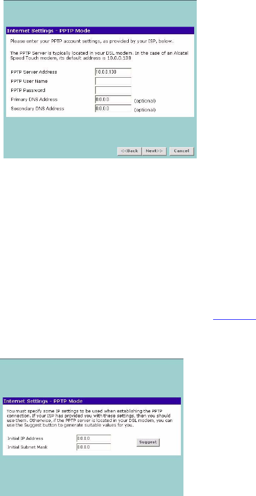
Figure 21 PPTP Mode Screen
To setup the Router for use with a PPTP connection, use the following
procedure:
1Enter your PPTP server address in the PPTP Server Address text box.
2Enter your PPTP user name in the PPTP User Name text box.
3Enter your PPTP password in the PPTP Password text box.
4Enter your Primary DNS Address and Secondary DNS address.
Your ISP may provide you with primary and secondary DNS addresses. If
they have been provided, enter the addresses in the appropriate text
boxes. If not, leave 0.0.0.0 in the boxes.
5Check all of your settings, and then click Next. Figure 22 displays.
Figure 22 PPTP IP Settings
38 CHAPTER 4: RUNNING THE SETUP WIZARD
6IP settings must be used when establishing a PPTP connection. Fill in the
Initial IP Address and the Initial Subnet Mask fields if your ISP has
provided you with these settings. Alternatively, if the PPTP server is
located in your DSL modem, click Suggest to select an IP address on the
same subnet as the PPTP server.
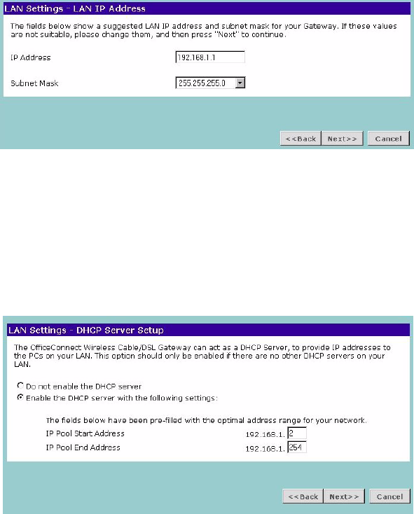
LAN Settings Figure 23 LAN IP Address Screen
This screen displays a suggested LAN IP address and subnet mask of the
Router. It also allows you to change the IP address and subnet mask.
DHCP The Router contains a Dynamic Host Configuration (DHCP) server that
can automatically configure the TCP/IP settings of every computer on
your network.
Figure 24 DHCP Server Setup Screen
To activate the DHCP Server option, select Enable the DHCP server with
the following settings: and specify the IP pool range. The largest available
continuous IP pool will be automatically entered; if this is not appropriate,
Accessing the Wizard 39
make your required changes. To disable DHCP, select Do not enable the
DHCP server. Click Next when you have finished.
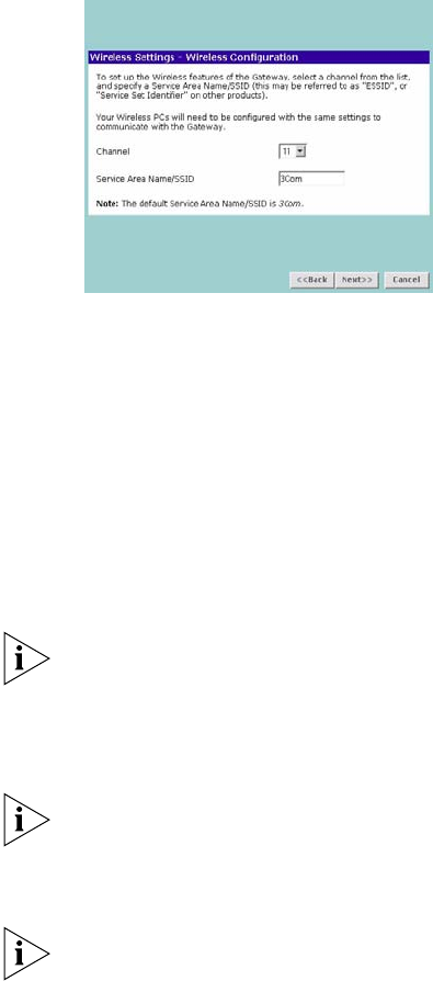
Wireless Settings Figure 25 Wireless Configuration Screen
This screen displays the Channel and Service Area Name. It also allows
you to change these settings. There are a maximum of 14 channels, the
number available to you is dependent on the country you reside in.
Selecting Clear Channel Select allows the Router to automatically select
an available channel when first powered on.
The Service Area Name default for 3Com products is “3Com”. Up to 32
(case sensitive) characters can be entered for the Service Area Name.
3Com strongly recommends that you change the SSID to something
other than the default.
If you are configuring the Router from a wireless computer any changes
you make to the wireless configuration will result in communication
between the Router and your computer being lost. This is why 3Com
strongly recommends that you configure the Router from a wired
computer.
It is very important that you set up your wireless clients to use the same
Service Area Name or SSID as the one you use on this screen. If your
clients use a different Service Area Name then they will not be able to
communicate with the Router.
The choice of channel is less important as Clients will generally search all
of the available channels. You should however make a note of the
40 CHAPTER 4: RUNNING THE SETUP WIZARD
channel you select as this may be useful if you experience problems with
your clients.
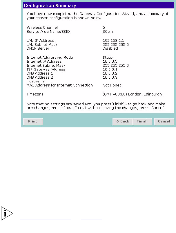
Summary Figure 26 Configuration Summary Screen
When you complete the Setup Wizard, a configuration summary will
display. Verify the configuration information of the Router and then click
Finish to save your settings. 3Com recommends that you print this page
for your records.
If you have made changes to the LAN Settings or wireless configuration
options, you may need to reconfigure the computer you are using in
order to make contact with the Router again.
Your Router is now configured and ready for use.
For information on improving your Wireless network security see
“Wireless Settings” on page 47.
See Chapter 5 for a detailed description of the Router configuration
screens.

5ROUTER CONFIGURATION
Navigating
Through the Router
Configuration
Pages
This chapter describes all the screens available through the Router
configuration pages, and is provided as a reference. To get to the
configuration pages, browse to the Router by entering the URL in the
location bar of your browser. The default URL is http://192.168.1.1
but if you changed the Router LAN IP address during initial configuration,
use the new IP address instead. When you have browsed to the Router,
log in using your system password (default admin).
Main Menu At the left side of all screens is a main menu, as shown in Figure 27 on
page 42. When you click on a topic from the main menu, that page will
appear in the main part of the screen.
■Welcome — displays the firmware version of the Router, allows you to
change your password, and launch the Wizard
■LAN Settings — allows you to configure IP address and subnet mask
information, set up DHCP server parameters, and display the DHCP
client list.
■Wireless Settings — enables /disables access from wireless computers,
and provides facilities for improving the security of the wireless
network.
■Internet Settings — sets up Internet addressing modes such as PPPoE
and PPTP connections, allows you to clone the Router’s MAC address,
and set up dynamic IP address allocation and static IP address settings.
■Firewall — allows configuration of the Router’s firewall features:
Virtual Servers, Special Applications, PCs Privileges, URL Filtering and
Security options
■System Tools — allows the administrator to perform maintenance
activities on the Router.
42 CHAPTER 5: ROUTER CONFIGURATION
■Status and Logs — displays the current status and activity logs of the
Router.
■Support/Feedback — contains a comprehensive online help system
and allows you to provide 3Com with feedback on your Router.
Option Tabs Each corresponding menu page may also provide sub-sections which are
accessed through the use of tabs (see Figure 27 for example). To access a
sub-section, simply click on the required tab.
Getting Help
On every screen, a Help button is available which provides access to the
context-sensitive online help system. Click Help for further assistance and
guidance relating to the current screen.
Welcome Screen The Welcome section allows you to view the Notice board and to change
your Password. You can also gain access to the Configuration Wizard.
(See “Accessing the Wizard” on page 29 for details).
Notice Board Figure 27 Notice Board Screen
The Notice Board is used to display configuration warning messages. For
example, you would be warned if you had disabled wireless networking
or wireless encryption.
Welcome Screen 43
Password Figure 28 Password Screen
Changing the Administration Password
You can change the password to prevent unauthorized access to the
Administration System. To do this:
1Enter the current password in the Old Password field
2Enter the new password in the New Password field
3Enter the new password again in the Confirm Password field
4Click Apply to save the new password
The password is case sensitive.
If you have forgotten your password you need to reset the Router. See
“Forgotten Password and Reset to Factory Defaults” on page 85
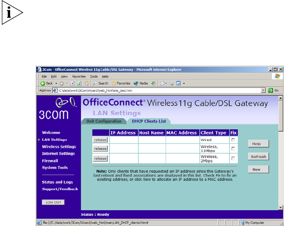
LAN Settings 45
The LAN Settings screen is used to specify the LAN IP address of your
Router, and to configure the DHCP server.
1Select Unit Configuration and then specify the Router IP Address and
Subnet Mask in the LAN Settings field. The default IP address of the
Router is 192.168.1.1.
2If you want to use the Router as a DHCP Server, click in the Enable check
box.
3Clicking Auto Range will automatically choose the largest available range
of addresses for your network.
4Check all of your settings, and then click Apply.
The DHCP server will give out addresses to both wired and wireless
clients.
DHCP Clients List Figure 31 DHCP Clients List Screen
The DHCP Clients List provides details on the devices that have received IP
addresses from the Router. The list is only created when the Router is set
up as a DHCP server. For each device that is connected to the LAN the
following information is displayed:
■IP address — The Internet Protocol (IP) address issued to the client
machine.
■Host Name — The client machine’s host name, if configured.
■MAC Address — The Media Access Control (MAC) address of the

46 CHAPTER 5: ROUTER CONFIGURATION
■client’s network card.
■Client Type — Whether the client is connected to the Router by wired
or wireless connection.
■Fix — This box is checked if the IP address is fixed to the MAC address
of the client’s network card. Clients that have fixed addresses will get
the same IP address each time they connect.
Check the box to fix an association. Uncheck the box to remove the
fixed association.
As you connect more devices, the client list will grow to a maximum
number of 253 clients.
The release button allows the lease time for the IP address that has been
issued to a device to be cleared. The lease time is set at 12 hours. If a PC
has been switched off, using the Release button would allow the 12 hour
lease time to be cleared. The IP address would then be available for
another device if there were no other IP addresses available.
Adding Fixed DHCP Mappings
You can add Fixed Mappings so that the Router allocates an IP address
chosen by you when it encounters a particular device.
You only need to create Fixed Mappings for devices that need a specific IP
address. For devices that do not need a specific IP address, the Router will
automatically allocate addresses.
To add a Fixed Mapping:
1Click New. The DHCP Fixed Mapping Setup screen will be displayed.
2Enter the MAC Address for which you want to create a Fixed Mapping in
the MAC Address of Client box.
The MAC Address must be entered as 6 hexadecimal pairs, e.g.
12-34-56-78-90-ab.
3Enter the IP Address that you want to reserve in the IP Address for client
box.
4Click Add to add the Fixed Mapping or Close to close the window
without adding the Fixed Mapping.
The Fixed DHCP Mapping will be displayed in the DHCP Clients list as a
Fixed Association.
Wireless Settings 47
Wireless Settings
To improve the security of your wireless network, 3Com recommends
that you:
1. Change the SSID from its default value - see page 48
2. Enable Encryption - see page 49
3. Enable Connection Control - see page 53
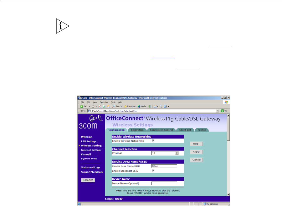
Configuration Figure 32 Configuration Screen
Enable Wireless Networking
Allows you to enable/disable the wireless section of your LAN. When
disabled, no wireless PCs can gain access to either the Internet or other
PCs on your Wired or Wireless LAN through this Router.
Channel Selection
The Channel Selector allows you to specify which Channel the Router will
transmit and receive on. If another access point or Router nearby is using
the same Channel as you, there will be a reduction in the performance of
your network. If this seems to be the case, you should select a different
channel number. Usually the Wireless computers will scan to find the
correct channel, but if they don't you must configure them to use the
same Channel number as the Router.

48 CHAPTER 5: ROUTER CONFIGURATION
Choose the Clear Channel Select option to automatically choose the
clearest channel. The Router will check for the clearest channel whenever
it is rebooted, powered up, and when the Clear Channel Select option is
first applied.
Valid channels are country dependent. See “Channels” on page 119 for a
list of channels approved by each country.
Service Area Name/SSID
This allows you to name your Wireless network. The field will accept any
alphanumeric string and has a maximum length of 32 characters. Your
Wireless computers must be configured with exactly the same name or
you will not establish a connection. The Service Area Name may also be
referred to as “ESSID” depending on your networking vendor. By default
the Router uses the name “3Com”. 3Com recommends that you change
the default name.
In order that your wireless computers can connect to the Router, you
must:
■Use Infrastructure Mode not Adhoc Mode.
■Have the same Service Area Name as the Router.
■Have the same Channel number as the Router.
■Use the same encryption type and keys as the Router.
■Ensure that the PC is included in the authorized Wireless PCs list if
Connection Control is enabled. See page 53.
Enable Broadcast SSID
This feature can be used to improve the security of your wireless network.
When the tickbox is checked, the Router will broadcast the Service Area
Name/SSID of your wireless network. This will allow unauthorized clients
from detecting your SSID and attempting to connect to your network.
If you have a wireless client that can detect all the available SSIDs in your
area, your client will not list the Router SSID unless this feature is enabled.
The clients will still be able to connect, provided that they are supplied
with the SSID.
3Com recommends that you install your wireless network with this
feature enabled and then disable it once you have set up the Router and
wireless clients.

Wireless Settings 49
Encryption When setting up wireless networks, it is important to remember that with
encryption disabled, anyone with a Wireless PC can eavesdrop on your
network. 3Com recommends that you get the network working with
encryption disabled first and then enable it as the last step. This will
simplify setting up your network.
The Router supports two types of encryption:
■WPA — Wi-Fi Protected Access (WPA) is a 256 bit encryption method
with keys that change over time.
■WEP — Wireless Equivalent Privacy (WEP) is a 64 bit or 128 bit
encryption method with user configurable fixed keys.
WPA provides a higher level of security, provided by its longer key and
dynamic changes made to the key over time. 3Com recommends that
you use WPA with any clients which support it.
If you enable encryption on the Router, you must reconfigure your
wireless PCs to use exactly the same Encryption Type and Keys otherwise
the devices will not understand each other.
The encryption methods used by the Router secure data transmitted
through wireless communications between the Router and its wireless
clients. Enabling encryption has no security effect on data transmitted
through wired (Ethernet) connections or through your connections to the
Internet.
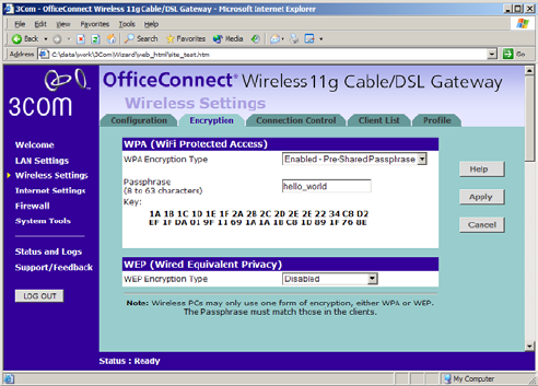
Configuring WPA
Encryption
The only configuration that is needed for WPA is to enter the pre-shared
key. This key is used to start the dialog between the Router and the client.
During this dialog, a new key is agreed, making it more difficult to
eavesdrop on wireless networks encrypted using WPA, than those
encrypted using WEP. The pre-shared key can be entered as a 256 bit
series of hexadecimal digits or as a pass-phrase.
50 CHAPTER 5: ROUTER CONFIGURATION
Figure 33 Encryption Keys Screen showing WPA configuration
To enter the pre-shared key as hexadecimal digits:
1Select Enabled - Manual Pre-shared Key from the WPA Encryption Type
drop-down box.
2Enter a pair of hexadecimal digits in each of the 32 Key fields. Each field
can contain a hexadecimal number from 00 to ff, for example 1a.
3Click Apply to generate the key.
To enter the pre-shared key as a pass-phrase:
1Select Enabled - Pre-Shared Passphrase from the WPA Encryption Type
drop-down box.
2Enter a phrase of between 8 and 63 characters in length in the
Passphrase field. This passphrase will be used to generate a 256 bit key.
3Click Apply to generate the key.
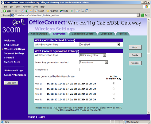
Configuring WEP
Encryption
There are two levels of WEP encryption available, 64 bit (sometimes
referred to as 40 bit) and 128 bit. Use the WEP Encryption Type box to
select the desired level.
Wireless Settings 51
Encryption Keys
Figure 34 Encryption Keys Screen showing WEP configuration
A Key is a hexadecimal (0-9, A-F) number used to encrypt and decrypt the
data. There can be up to 4 keys and each key can be as long as 26 digits.
The Router also offers a number of methods for converting plain text into
hex keys. The text is much easier to remember than hex keys but it relies
on your wireless adapters also supporting this feature. Different
manufacturers have developed different ways of converting plain text
and so interoperability is not guaranteed. If you are experiencing
difficulty, the Manual Hex Key method is supported by most vendors.
There are four methods available to generate the encryption keys:
■Manual Key Entry - This method allows you to manually enter hex
keys. Virtually all manufacturers support this scheme. Enter a two digit
hexadecimal number in every box. Hexadecimal numbers are formed
from 0-9 and A-F.
■3Com Encryption String - This method is supported by 3Com Wireless
products. The string can contain any alphanumeric characters and
must be between 6 and 30 characters long. A single string will
automatically generate 4 unique keys for 64 or 128 bit WEP.
■ASCII - This method is supported by some adapter cards running
under Windows XP. The string must be exactly 5 characters for 64 bit

52 CHAPTER 5: ROUTER CONFIGURATION
WEP and 13 characters for 128 bit WEP. You must enter a separate
string for each of the 4 Keys. You can leave a string blank provided
this Key is not selected as the Active Transmit Key.
■Passphrase - This is another common method and similar to the 3Com
Encryption string. In 64 bit WEP, the passphrase will generate 4
different keys. However, in 128 bit WEP, this method only generates 1
key which is replicated for all 4 keys. The passphrase can be up to 31
characters long and may contain any alphanumeric characters.
Select the key generation method you wish to use from the drop down
list. If you have other wireless products choose the scheme that is
compatible with these, then enter the appropriate information.
If you encounter any difficulty when you enable WEP ensure that you
check that each key on your wireless computer is exactly the same as
each key on your Router. In other words, Key number 1 on the Wireless
computer must have the same Hex number as Key number 1 on the
Router, Key 2 on the Wireless computer must match Key 2 on the Router
and so on.
The Active Transmit Key selects which of the 4 Keys the Router uses when
it transmits. You can change the selected key periodically to increase the
security of your network.
Some wireless adapters have only one key available on their WEP
configuration page. If this is the case ensure it is the same as Key 1 on the
Router and that it is selected as the active transmit key.
Wireless Settings 53
Connection Control Figure 35 Connection Control Screen
A higher level of security can be achieved for your wireless network if you
use both encryption and you specify only certain wireless computers can
connect to the Router. By default, any wireless computer that has the
same Service Area Name/SSID, channel and encryption settings as the
Router can connect to it.
Select Only Authorized Wireless PCs can connect to the Router to enable
and configure this feature.
If you enable this feature from a Wireless PC, it will automatically be
added to the Authorized Wireless PC list.
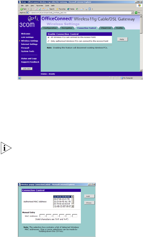
Authorized Wireless PCs
Figure 36 Connection Control Detail Screen
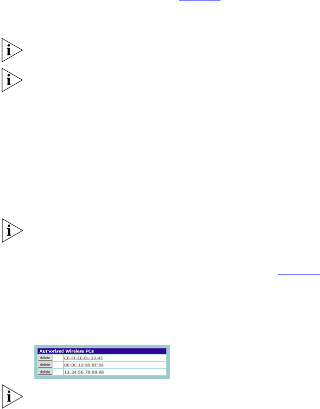
54 CHAPTER 5: ROUTER CONFIGURATION
To create a list of Wireless computers that can access the Router:
1Press New. The screen shown in Figure 36 opens.
2Select the MAC addresses of the Wireless PCs for which you want to
allow access.
To select multiple MAC addresses, hold down the Ctrl key while clicking
on the addresses.
The drop down list on the Connection Control window will contain the
MAC addresses of all Wireless PCs that are in range, currently operating,
and have the same Service Area Name/SSID, channel and encryption
settings as the Router. You will find this screen easier to use if you set up
and make a note of all of your wireless PC's on your network first. You
may also add the entries manually if you know the MAC address.
To add a MAC address that is not in the list, enter the MAC address in
the appropriate fields. A MAC address consists of 12 characters. Valid
characters are '0-9', and 'A-F'.
3Press Add.
Click Close to discard all changes.
Modifying a MAC Address
1Click on the MAC address to be modified in the table (Figure 37).
2Modify the MAC address.
3Press Apply to accept the changes.
Figure 37 MAC Address Table
Click Close to discard all changes.
Deleting a MAC Address
The connection rights for a Wireless PC listed in the table can be removed
by pressing Delete for that entry in the table.
Wireless Settings 55
Once an entry has been deleted it cannot be undone. Please wait 30
seconds for changes to take effect.
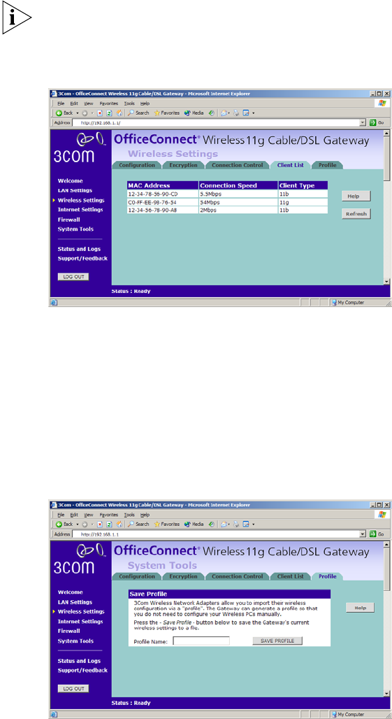
Client List Figure 38 Client List Screen
The Wireless Client List provides details on the devices that are connected
to the Wireless LAN. The list is only created when Wireless Networking is
enabled. For each device that is connected to the Wireless LAN, the MAC
address and Connection Speed of that device is displayed. As you
connect more devices to the Wireless LAN, the client list will grow to a
maximum of 32 (the maximum number of wireless devices that the
Router can support).
Profile Figure 39 Profile Screen

56 CHAPTER 5: ROUTER CONFIGURATION
Some 3Com Wireless Network Adapters allow you to import Wireless
configurations via a ‘profile’. The Router can generate a profile so that
you do not need to configure your Wireless PCs manually.
The profile contains three items as follows:
■Service Area Name/SSID of the Router
This is configured on the Configuration tab under the Wireless
Settings option.
■Encryption settings from the Router
This is configured on the Encryption tab under the Wireless Settings
option.
■Profile Name
This is used to identify the profile once it has been imported into the
Wireless Network Adapter configuration software.
To set up a profile (once the Service Area Name/SSID and Encryption
settings have been configured in the Router):
1Enter a Profile Name (up to 25 alphanumeric characters) and then click
Save Profile.
2Your browser will then prompt you to enter a file name and folder
location in which to save the profile. Once the profile has been saved it
can be copied on to another PC and imported into the 3Com Wireless
Network Adapter.
For instructions on how to import a profile, refer to the User Guide that
accompanies your 3Com Wireless Network Adapter(s).
If, once the profile is imported, the Wireless Network Adapter cannot
connect to the Router, check that:
■the adapter is within range of the Router
if Connection Control has been enabled in the Router, the MAC address
of the Wireless Network Adapter must be included in the list of
authorized Wireless PCs.

Internet Settings 57
Internet Settings Before you can configure the Router, you need to know the IP
information allocation method used by your ISP. There are four different
ways that ISPs can allocate IP information, as described below:
1 Static IP Address (DSL or Cable)
The ISP provides the IP addressing information for you to enter manually.
To configure the Router you will need to know the following:
■IP Address
■Subnet Mask
■ISP Router
■DNS address(es)
2 Dynamic IP Address (DSL or Cable)
Dynamic IP addressing (or DHCP) automatically assigns the Router IP
information. This method is popular with Cable providers. This method is
also used if your modem has a built in DHCP server.
3 PPPoE (DSL only)
If the installation instructions that accompany your modem ask you to
install a PPPoE client on your PC, then select this option. To configure the
Router you will need to know the following:
■Username
■Password
■Service Name (if required by your ISP)
When you install the Router, you will not need to use the PPPoE software
on your PC.
4 PPTP (DSL or Cable)
PPTP is only used by some European providers. If the installation
instructions that accompany your modem ask you to setup a dialup
connection using a PPTP VPN tunnel then select this option. To configure
the Router you will need to know the following:
■Username
■Password
■VPN Server address (usually your modem)
58 CHAPTER 5: ROUTER CONFIGURATION
When you install the Router, you will not need to use the dialup VPN on
your PC anymore.
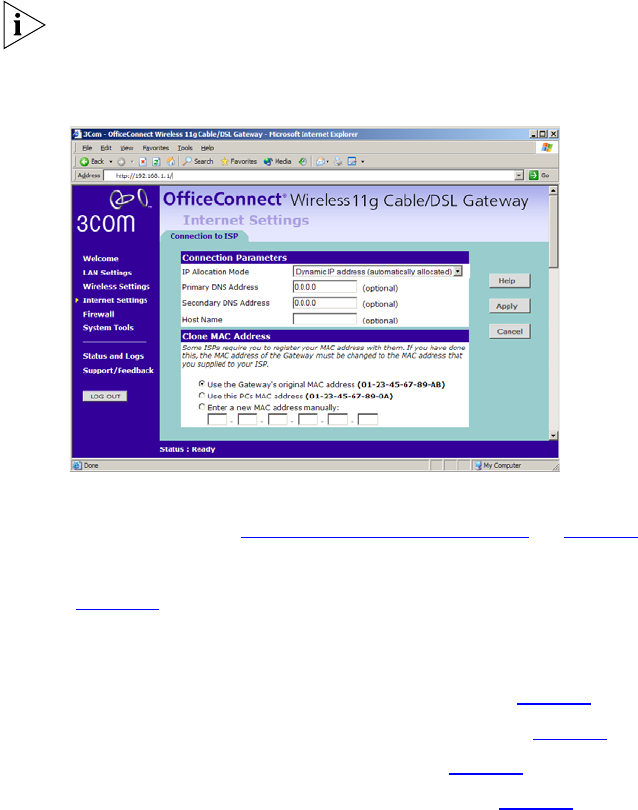
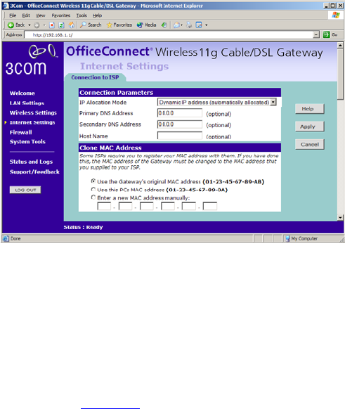
Connection to ISP Figure 40 Connection to ISP Screen
Before beginning this section, ensure you have the required information
from your ISP. (See “Before you Install your Router” on page 21.)
Select Internet Settings from the main menu to display Connection to ISP
(Figure 40). Choose an IP Allocation Mode from the drop down box.
Select an IP Allocation Mode from the following:
■Static IP address (to be specified manually) see page 59
■Dynamic IP address (automatically allocated) see page 60
■PPPoE (used by DSL providers only) see page 61
■PPTP (used by some European providers) see page 62
Internet Settings 59
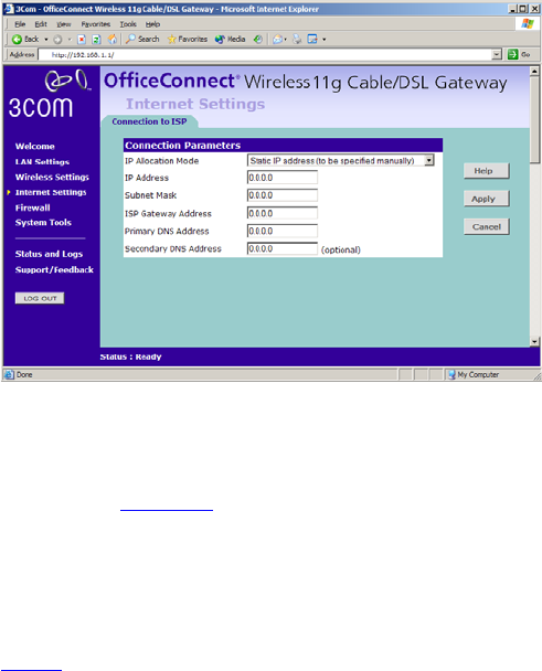
Static IP Address
Figure 41 Connection Parameters Screen - Static IP
To setup the Router for use with a Static IP address connection:
1Select Static IP Address (to be specified manually) in the IP Allocation
Mode field (Figure 41).
2Enter your IP Address in the IP Address text box.
This information, along with the rest of the information in this screen,
should be provided to you by your ISP. If the information is already
entered, your ISP has pre-configured your Router, and you should go to
step 7.
3Enter your subnet mask in the Subnet Mask text box.
4Enter your ISP Router address in the ISP Router Address text box.
5Enter your primary DNS address in the Primary DNS Address text box.
6Enter your secondary DNS address in the Secondary DNS Address text
box.
This step is optional. Not all ISPs require a secondary DNS address.
7Check all of your settings, and then click Apply.
60 CHAPTER 5: ROUTER CONFIGURATION
Dynamic IP Address
Figure 42 Connection Parameters Screen - Dynamic IP
If this mode is selected, your IP Address, Subnet Mask, and DNS Address
will be obtained automatically from your ISP. They are not displayed on
this screen, but may be viewed on the Status screen (click on Status and
Logs on the left hand menu bar).
To setup the Router for use with a dynamic IP address connection:
1Select Dynamic IP Address (automatically allocated) in the IP Allocation
Mode field. (Figure 42)
2Enter your Primary DNS Address and Secondary DNS address.
Your ISP may provide you with primary and secondary DNS addresses. If
they have been provided, enter the addresses in the appropriate text
boxes. If not, leave 0.0.0.0 in the boxes.
3Enter the Host Name (optional).
Some ISPs require a host name. If your ISP has this requirement, enter the
host name in the Host Name text box.
4If you use ‘Cable’, your ISP may use your MAC address to authenticate
you. If this is the case, you will need to ‘Clone’ your MAC address. There
are three options:
■Use the Router’s original Internet MAC address - This field is selected
by default and is automatically filled in with the MAC address of the
Router.