Arcadyan Technology WG4005DARC OfficeConnect Wireless 11g Cable/DSL Router User Manual DUA0055 4AAA01rev01
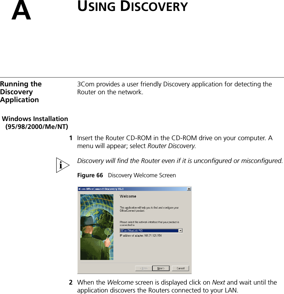
Arcadyan Technology Corporation OfficeConnect Wireless 11g Cable/DSL Router DUA0055 4AAA01rev01
Contents
- 1. user manual part 1
- 2. user manual part 2
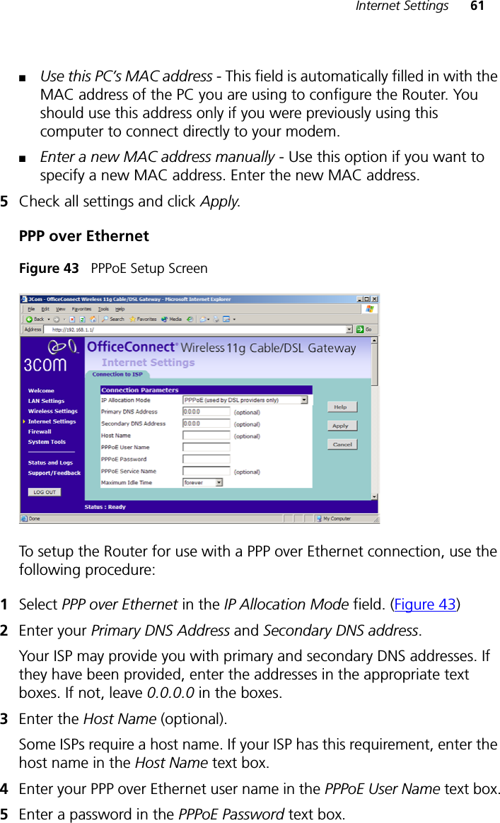
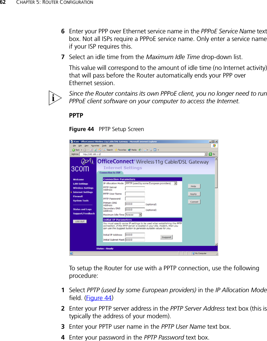
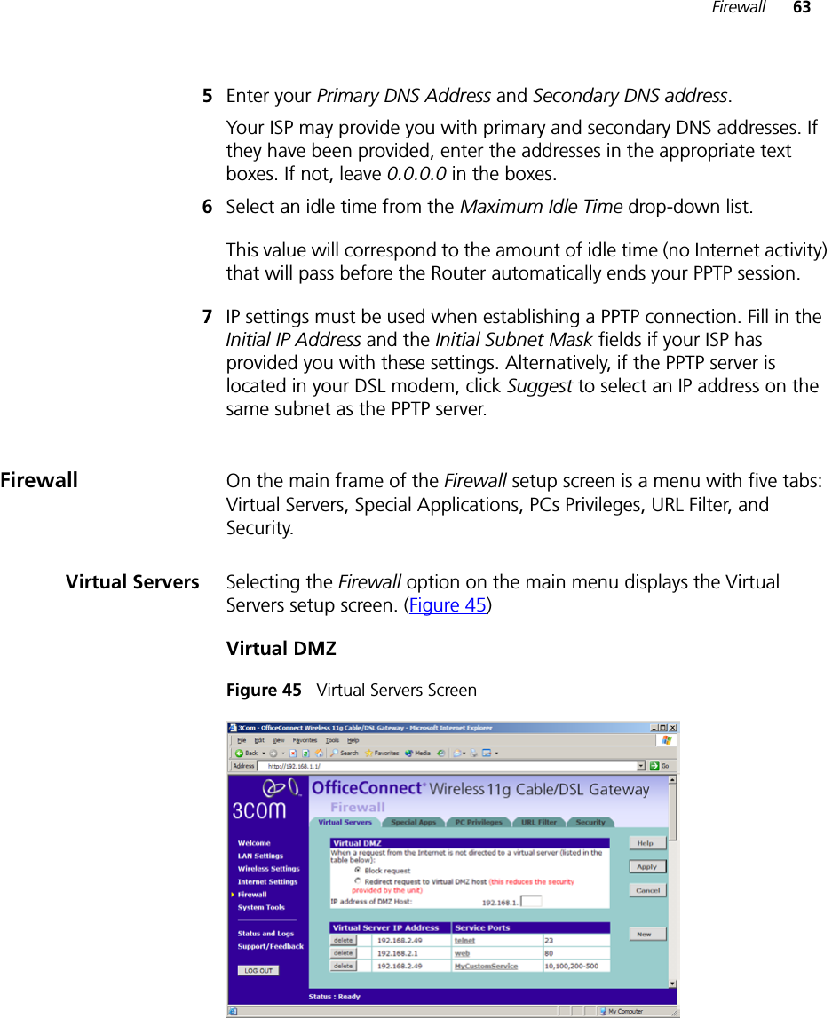
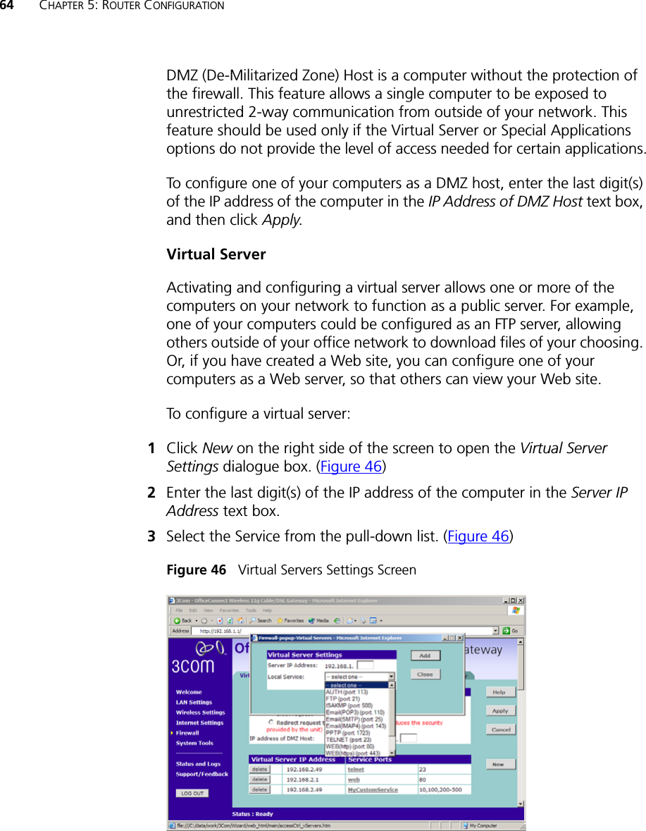
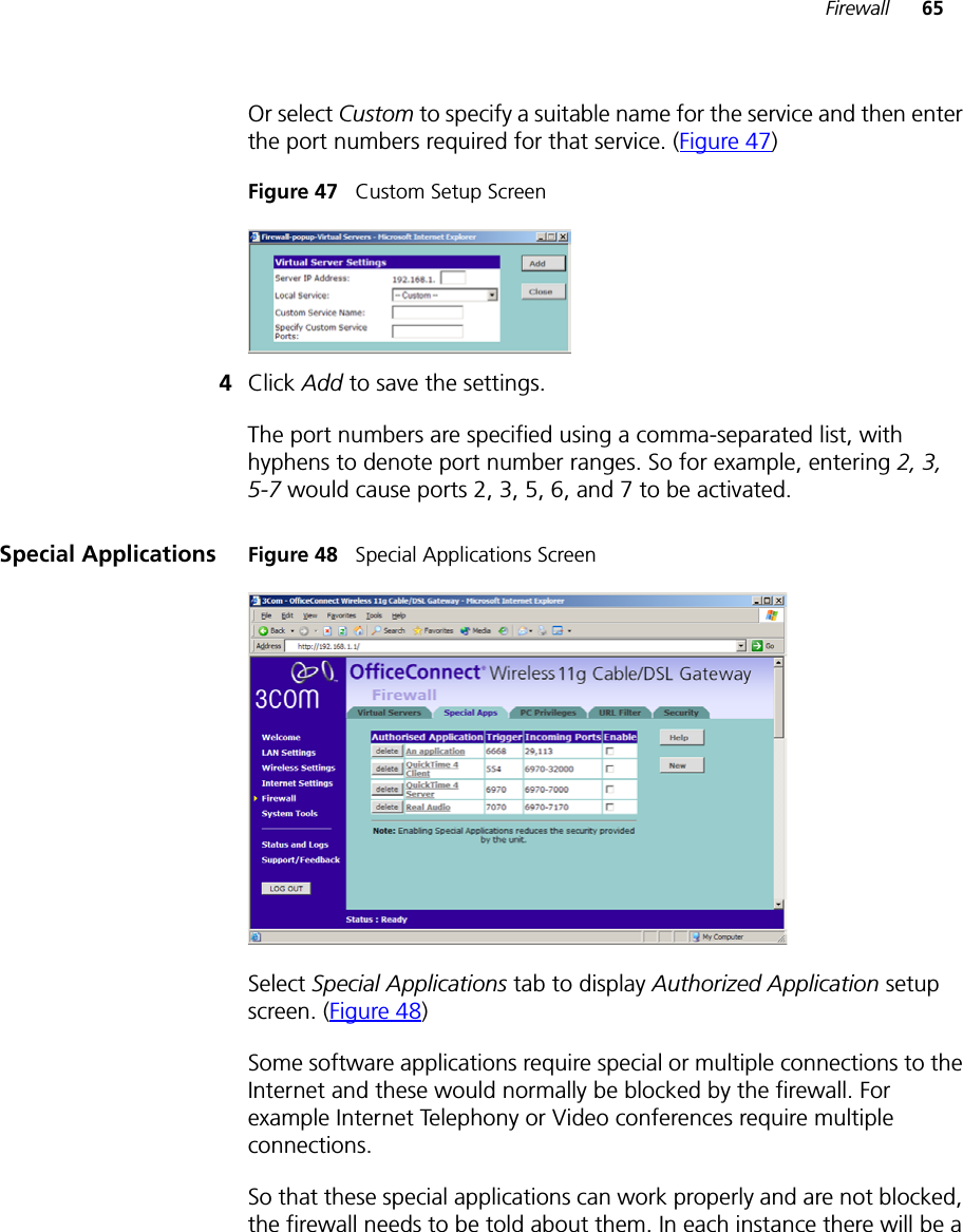
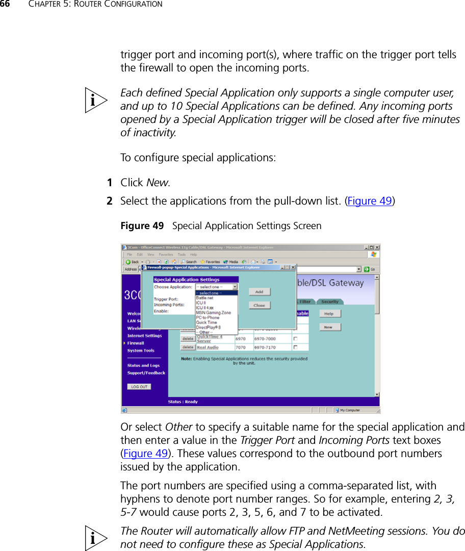
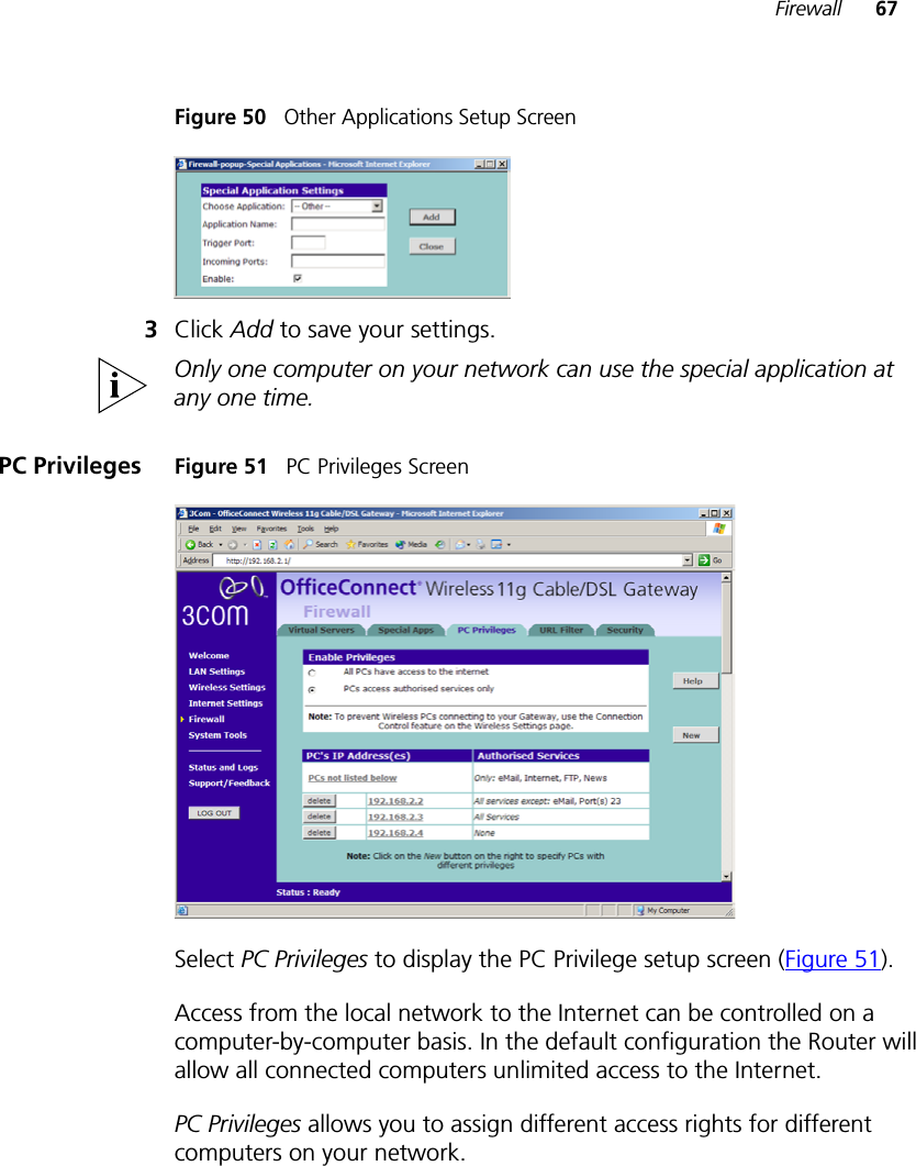
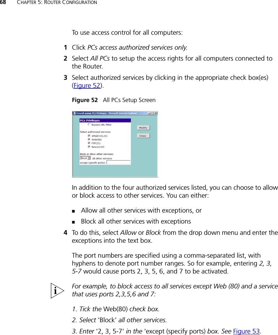
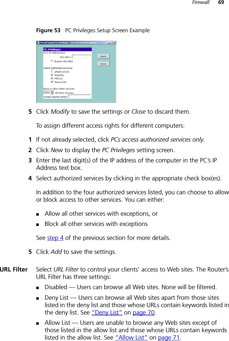
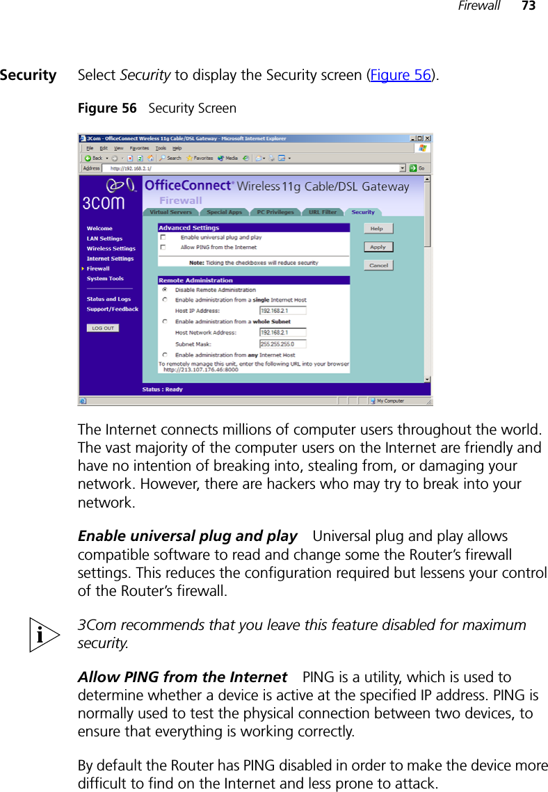
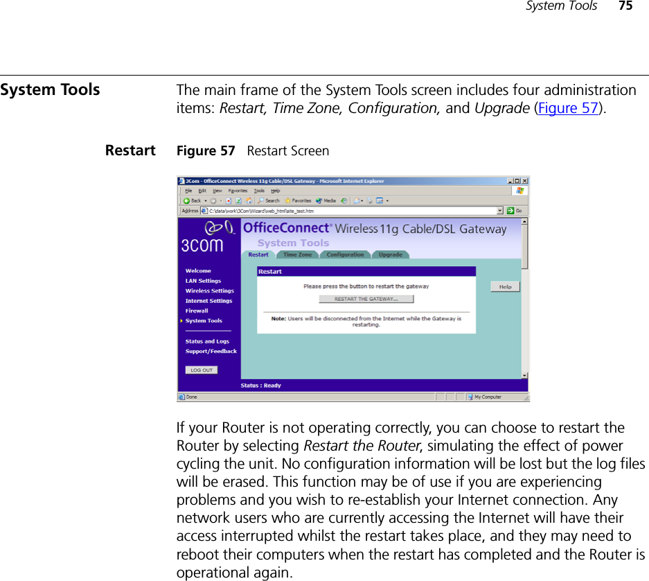
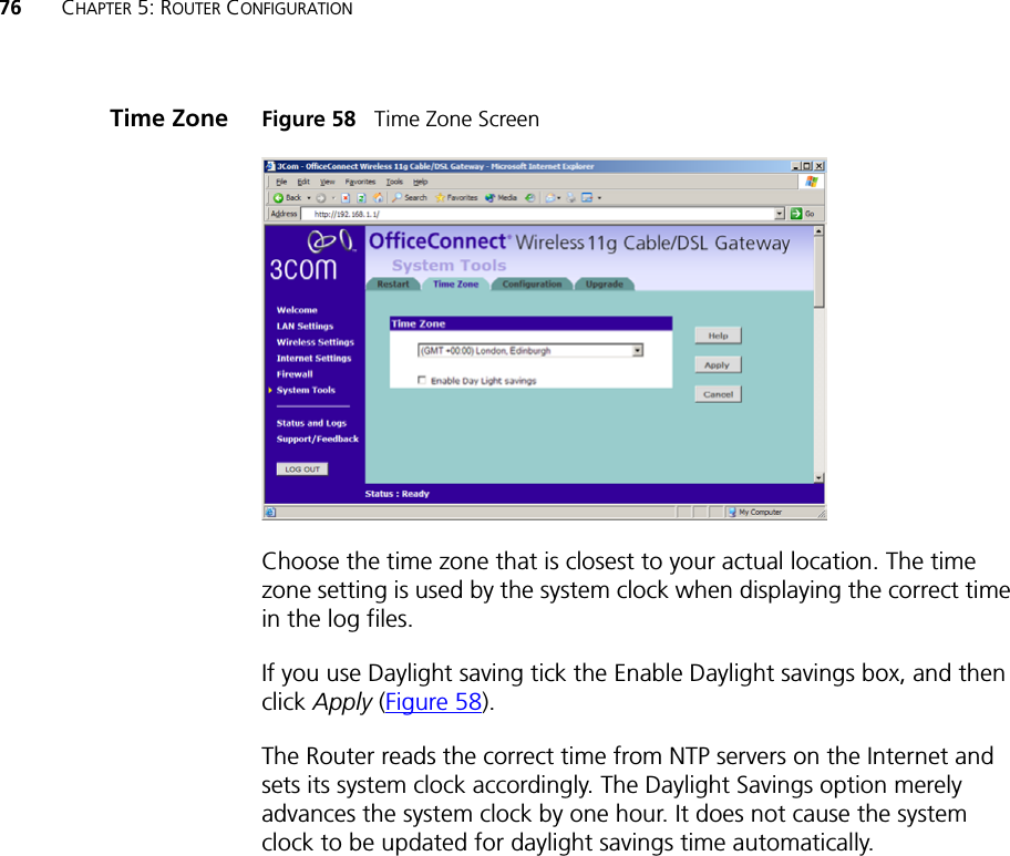
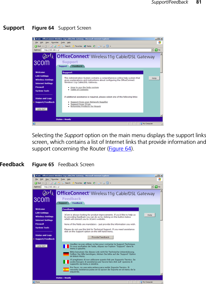
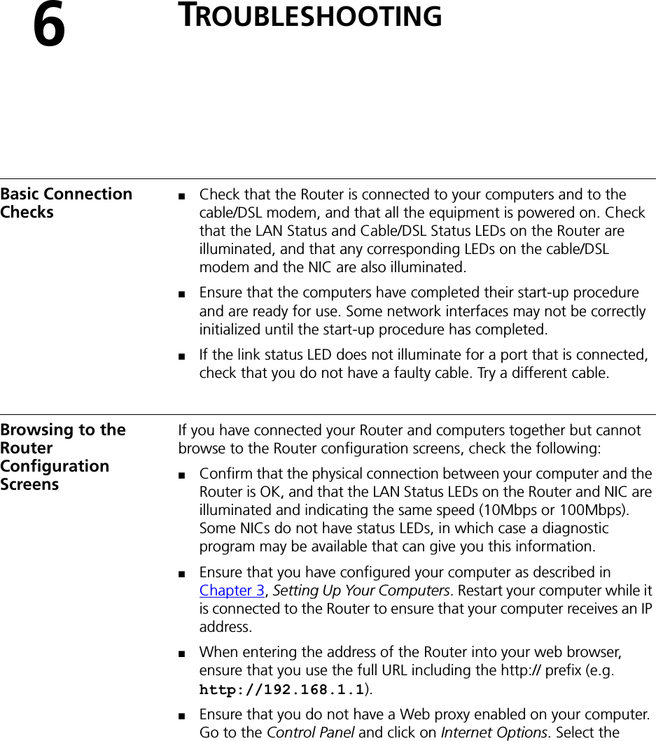
user manual part 2