Arcadyan Technology WN4501CARC OfficeConnect Wireless 11g USB Adapter User Manual 802 11g WLAN USB Stick QSG Manual
Arcadyan Technology Corporation OfficeConnect Wireless 11g USB Adapter 802 11g WLAN USB Stick QSG Manual
User Manual

1
8
80
02
2.
.1
11
1g
g/
/b
b
W
WL
LA
AN
N
U
US
SB
B
S
St
ti
ic
ck
k
WN-250gi
Quick Start Guide
No part of this documentation may be reproduced in any form or by any
means or used to make any derivative work (such as translation,
transformation, or adaptation) without written permission from the
copyright owner.
All the other trademarks and registered trademarks are the property of their
respective owners.
Statement of Conditions
We may make improvements or changes in the product described in this
documentation at any time. The information regarding to the product in this manual
are subject to change without notice.
We assume no responsibility for errors contained herein or for direct, indirect,
special, incidental, or consequential damages with the furnishing, performance, or
use of this manual or equipment supplied with it, even if the suppliers have been
advised of the possibility of such damages.
Electronic Emission Notices
This device complies with Part 15 of the FCC Rules. Operation is subject to the
following two conditions:
(1) This device may not cause harmful interference.
(2) This device must accept any interference received, including interference that
may cause undesired operation.
FCC INFORMATION
The Federal Communication Commission Radio Frequency Interference Statement
includes the following paragraph:
The equipment has been tested and found to comply with the limits for a Class B
Digital Device, pursuant to part 15 of the FCC Rules. These limits are designed to
provide reasonable protection against harmful interference in a residential
installation. This equipment generates, uses and can radiate radio frequency energy
and, if not installed and used in accordance with the instruction, may cause harmful
interference to radio communication. However, there is no guarantee that
interference will not occur in a particular installation. If this equipment does cause
harmful interference to radio or television reception, which can be determined by
turning the equipment off and on, the user is encouraged to try to overcome the
interference by one or more of the following measures:
--Reorient or relocate the receiving antenna.
--Increase the separation between the equipment and receiver.
--Connect the equipment into an outlet on a circuit different from that to which the
receiver is connected.
--Consult the dealer or an experienced radio/TV technician for help.
3
The equipment is for home or office use.
R&TTE Compliance Statement
This equipment complies with all the requirements of the Directive 1999/5/EC of the
European parliament and the council of 9 March 1999 on radio equipment and
telecommunication terminal Equipment and the mutual recognition of their
conformity(R&TTE).
The R&TTE Directive repeals and replaces in the directive 98/13/EEC. As of April 8,
2000.
IMPORTANT NOTE
FCC RF Radiation Exposure Statement: This equipment complies with FCC RF
radiation exposure limits set forth for an uncontrolled environment. This device
has been tested for compliance with FCC RF Exposure (SAR) limits in
typical laptop configurations and This Transmitter must not be co-located or
operating in conjunction with any other antenna or transmitter.
Caution: Changes or modifications not expressly approved by the party responsible
for compliance could void the user's authority to operate the equipment.

4
DGT Statement:
依據交通部電信總局低功率電波輻射性電機管理辦法;
第十四條
經型式認證合格之低功率射頻電機,非經許可,公司、商號或使用者均不得擅自
變更頻率、加大功率或變更原設計之特性及功能。
第十七條
低功率射頻電機之使用不得影響飛航安全及干擾合法通信;經發現有干擾現象
時,應立即停用,並改善至無干擾時方得繼續使用。
前項合法通信,指依電信法規定作業之無線電通信。
低功率射頻電機須忍受合法通信或工業、科學及醫療用電波輻射性電機設備之干
擾。

5
Table of Contents
Installation Procedures...........................................................................................6
Verifying a Successful Installation.......................................................................11
Basics of the Attached Configuration Tool..........................................................12
Step 1: Advanced Tab...................................................................................12
Step 2: Configuration Tab ............................................................................12
Step 3: Security Tab .....................................................................................13
Other Tabs ....................................................................................................14
6
I
In
ns
st
ta
al
ll
la
at
ti
io
on
n
P
Pr
ro
oc
ce
ed
du
ur
re
es
s
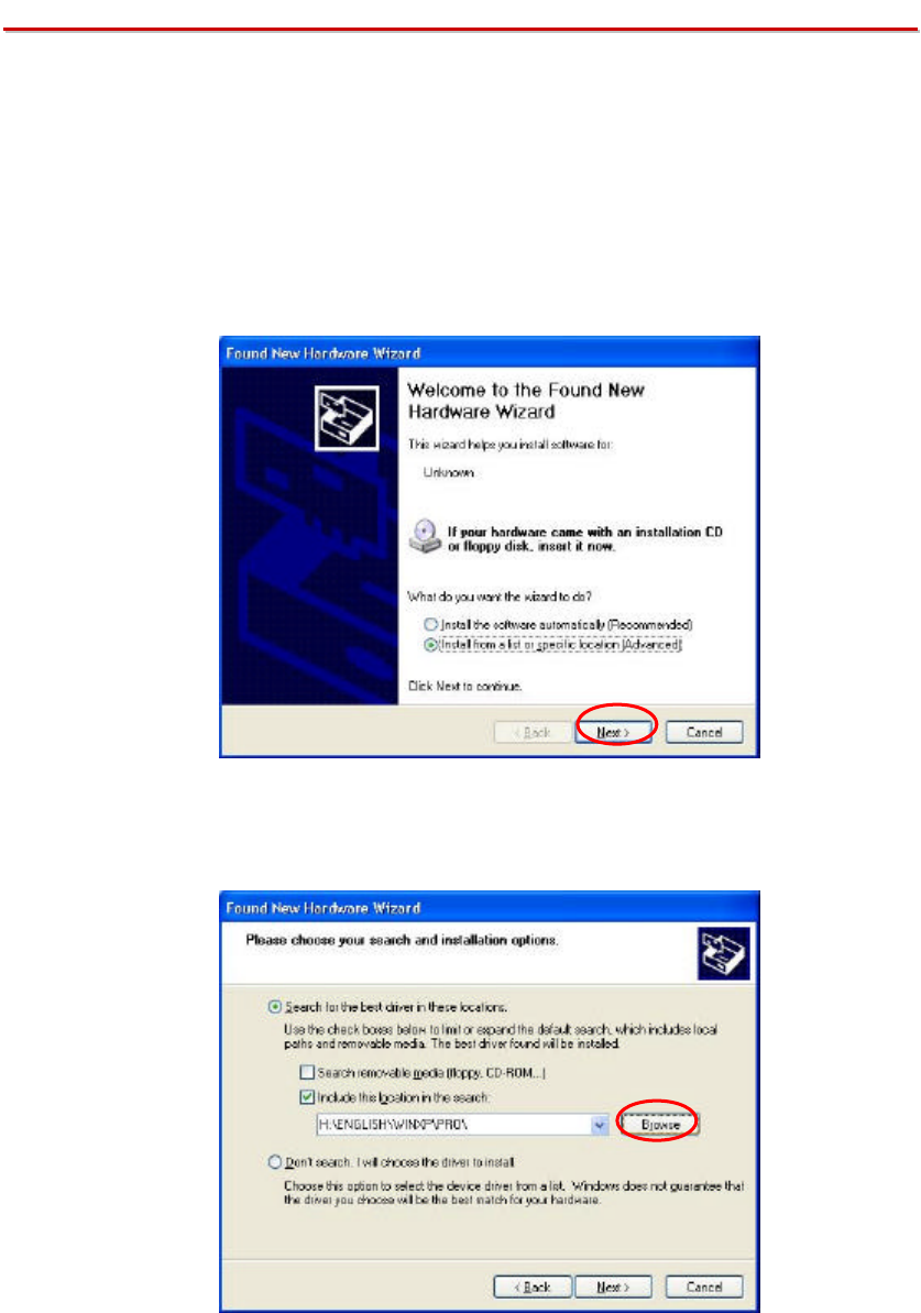
To have the 802.11g/b WLAN USB Stick operated appropriately, please read and go
along with the instructions below carefully. Here we take Windows XP as an example.
1. Plug your 802.11 g/b WLAN USB Stick into a USB 2.0 port on your PC.
2. Your system will detect the device, and the Found New Hardware Wizard
dialog box will appear. Choose Install from a list or specific location
[Advanced], and then click Next to proceed.
3. From the next dialog box, before choosing Include this location in the search
under Search for the best driver in these locations, insert the supplied Setup
CD into your CD-ROM drive. Then choose Browse.
4. In the opened Browse for Folder dialog box, specify a directory named Install
from the CD for the system. Then click OK.
7
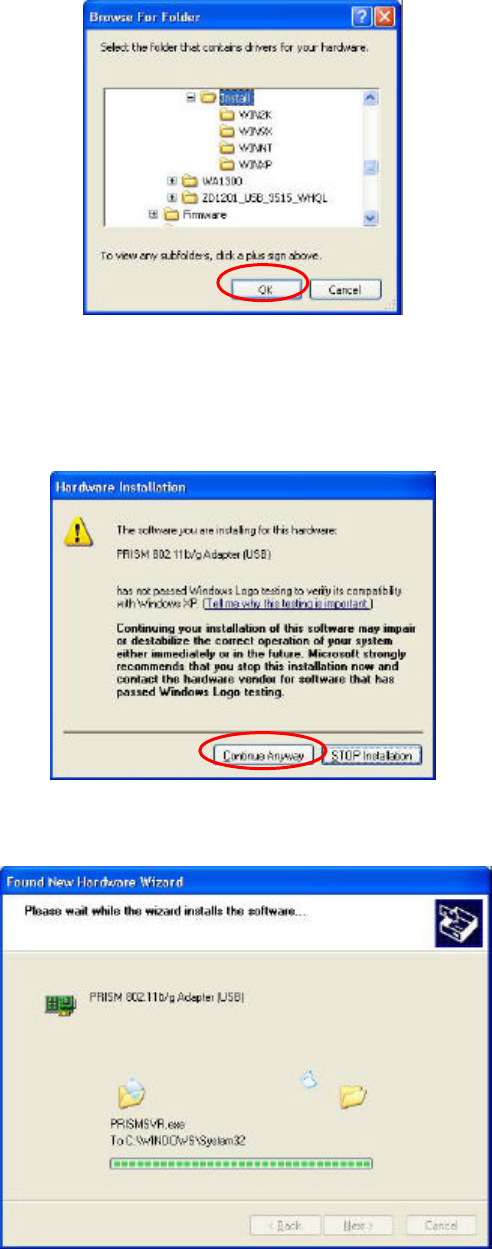
5. When return to the Found New Hardware Wizard dialog box, please choose
Next to continue the installation.
6. Choose Continue Anyway when the system displays the Hardware Installation
dialog box.
7. Your system will start to copy the drivers found. This might take a couple of
minutes. Then choose Next to proceed.
8. When the following dialog box appears, choose Finish to entirely complete the
installation.
8
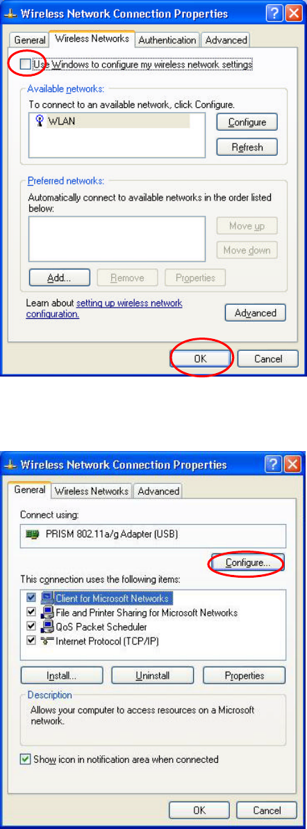
Windows XP has its built-in configuration tools – Windows XP Zero Configuration
to assist you in networking activities, however, we recommend you to employ the
attached software instead. Please proceed to the next step to change the default
settings of Windows Zero Configuration to the attached configuration tool.
9. Right-click the Network Connections icon at the task bar to open the Wireless
Network Connection Status dialog box, and then select Properties.
10. Choose the Wireless Networks tab in the Wireless Network Connection
Properties dialog box, and remove the tick from the Use Windows to configure
my wireless network settings checkbox.
9
11. Choose the General tab to display the following screen. Then click the
Configure button.
12. In the prompted PRISM 802.11 g/b Adapter (USB) Properties dialog box, you
may freely monitor and configure the network via the contained nine tabs.
10
For more details on the configuration, please refer to the “Basics of the Attached
Configuration Tool” in this manual.
11
V
Ve
er
ri
if
fy
yi
in
ng
g
a
a
S
Su
uc
cc
ce
es
ss
sf
fu
ul
l
I
In
ns
st
ta
al
ll
la
at
ti
io
on
n
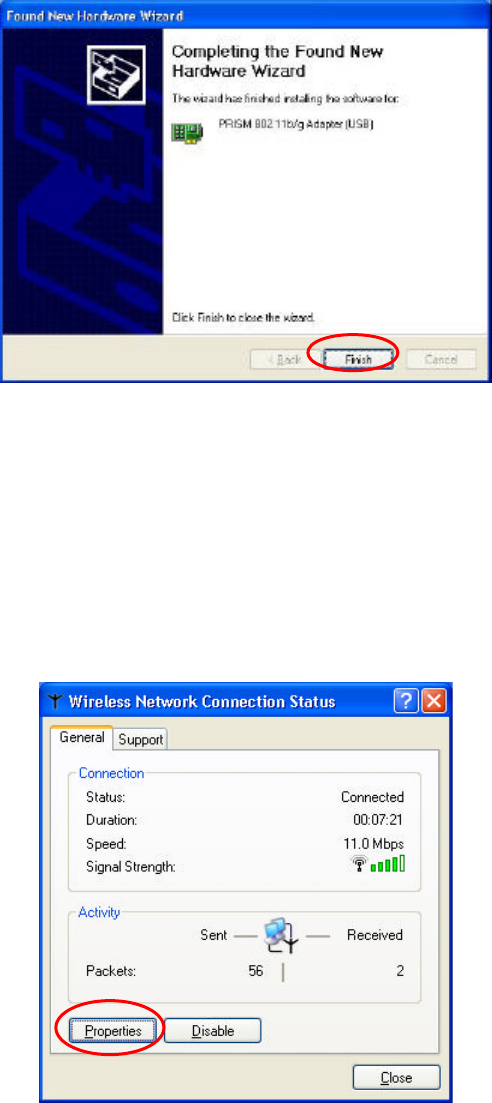
To confirm that your 802.11 g/b WLAN USB Stick is properly installed, please go
along with the procedures below.
1. Right-click the My Computer desktop icon and choose Properties from
the opened menu.
2. In the System Properties dialog box, click the Hardware tab, and then
choose the Device Manager button.
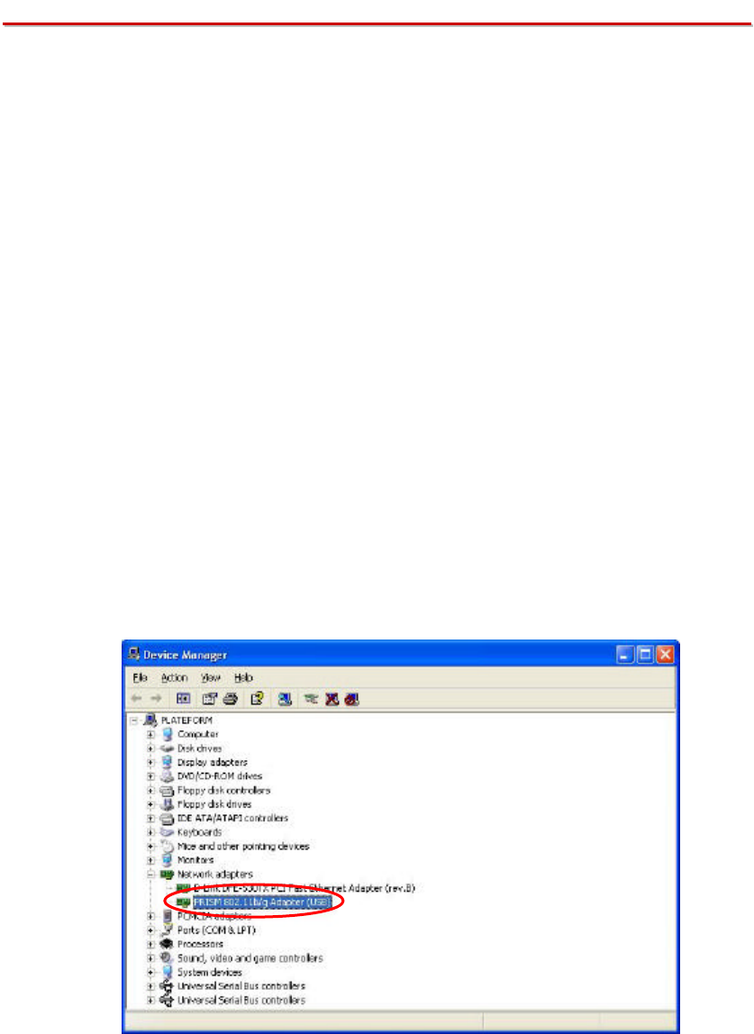
3. In the opened window, expand Network adapters to find the USB 802.11
g/b WLAN USB Stick – PRISM 802.11 g/b Adapter (USB). Right-click
over the item and choose Properties.
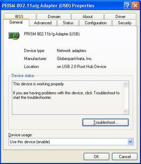
4. From the opened dialog box, on the General tab, find the descriptions under
the Device Status pane to learn if the USB 802.11 g/b WLAN USB Stick is
working properly. However, if there’s an error message shown, please
choose Uninstall from the opened menu while right-clicking the USB
Adapter item, to which a red or yellow icon is attached beside, in the Device
Manager dialog box. Then restart your system and go through the
installation procedures again.
The following picture indicates a successful installation of the 802.11g/b WLAN USB
Stick.
12
B
Ba
as
si
ic
cs
s
o
of
f
t
th
he
e
A
At
tt
ta
ac
ch
he
ed
d
C
Co
on
nf
fi
ig
gu
ur
ra
at
ti
io
on
n
T
To
oo
ol
l
In the following section, you will be guided through the basic 3-step workflows of
configuring your network via the prompted attached configuration tool. Please read
carefully to start the task.
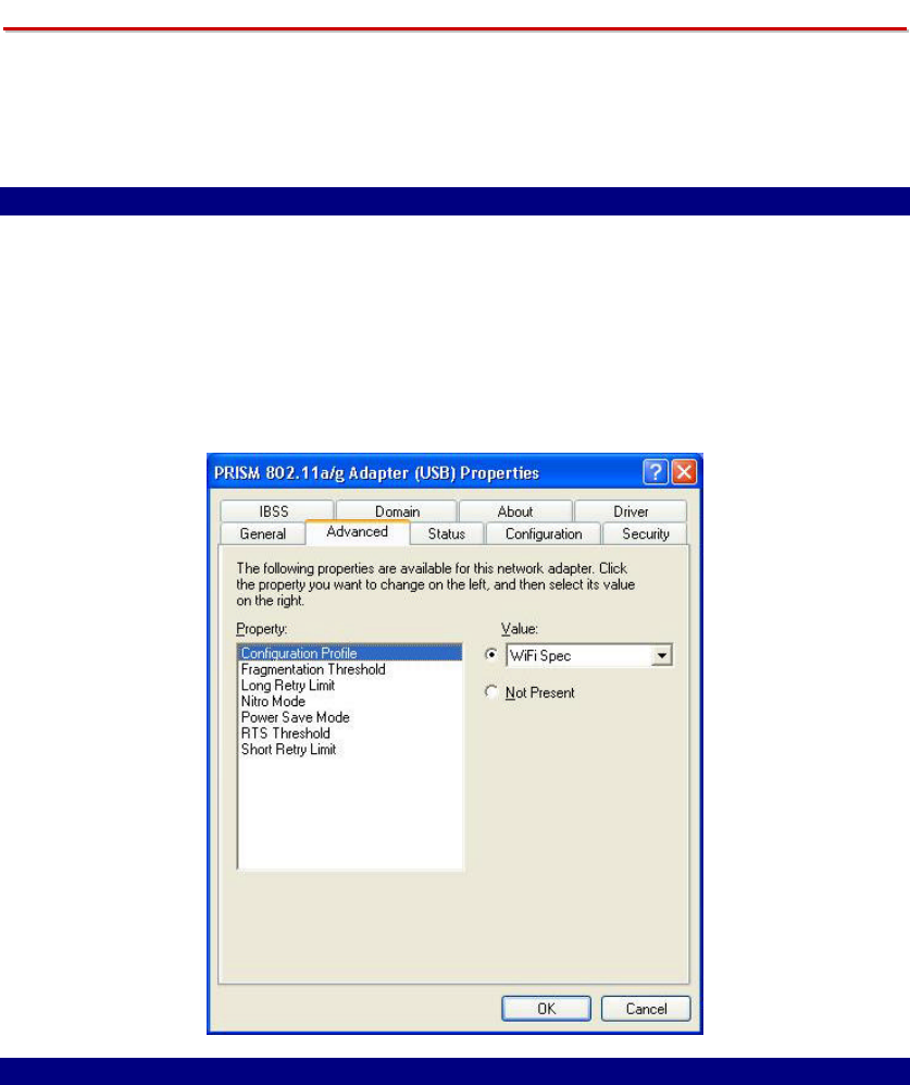
Step 1: Advanced Tab
Firstly, choose this tab to define the network standard you wish to use.
a) On the Advanced tab, choose Configuration Profile from Property.
b) Define which network standard you intend to operate from the Value
drop-down menu. WiFi Sepc is the default value. To use both 802.11b and
802.11g network standards, please choose Mixed.
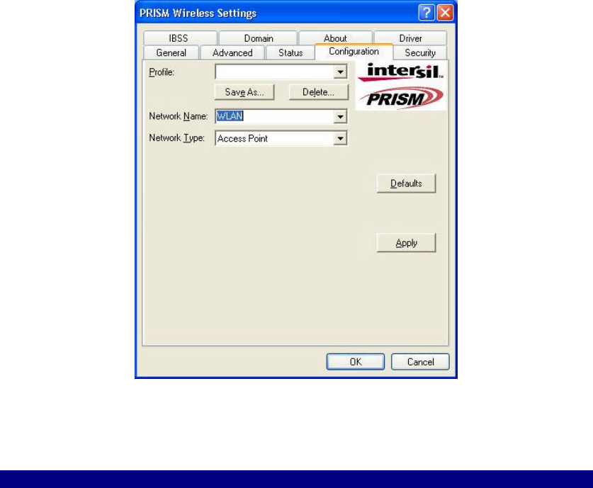
Step 2: Configuration Tab
Click this tab to edit different profiles for different network configurations.
a) Specify the network types as Access Point and Peer-to-Peer from the
Network Type area.
b) Type the identical SSID in the Network Name field to associate with access
points or stations within the specified wireless LAN.
c) Click Apply to establish the connection.
d) If you wish to create a new profile for the current association, please enter
texts in the Profile Name field and then click Save As to identify a new
profile. You may switch between any existing profiles by clicking the arrow
button at the right of the Profile Name field to open the pull-down menu and
13
then select an intended one from it.
Tips: To obtain the general information on the status of currently connected
entry, click the Status tab.
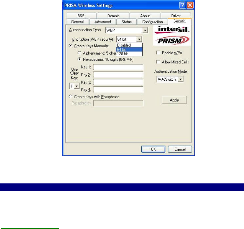
Step 3: Security Tab
To maintain the secure management in a wireless LAN environment, click the
Security tab to define the encryption settings for a specific profile. This tab offers you
various options concerning the so-called WEP (Wired Equivalent Privacy).
a) Define the Authentication Type as WEP.
b) Specify the key length from the two offered options: 64 bit or 128 bit from
the Encryption (WEP security) drop-down menu.
c) Now you may choose to edit WEP keys manually or create them via the
passphrase of your wireless network. If you choose the Create Keys
Manually option, you may directly enter up to 4 WEP keys for use in WEP
encryption. To generate the WEP keys, please define the key entry method as
Alphanumeric or Hexadecimal (for hexadecimal characters, only digits 0-9
and letters A-F are valid).
d) Then edit the texts in the blank fields below, from Key 1 to Key 4, as the
encryption codes. Note that these codes/keys shall be identical between the
wireless nodes within the range and the access point only.
e) Indicate which WEP key you intend to apply to activate the WEP encryption
from the Use WEP Key drop-down menu. Make sure that the intended
access point on the wireless network shares the same keys.
14
f) When the associated wireless network uses a passphrase to create WEP keys,
you may select Create Keys with Passphrase, and then enter the passphrase
string in the Passphrase filed to generate four encryption keys in the Key
fields above. Note that only letters A-F are valid for the Passphrase feature.
g) Indicate the Authentication Mode as Open, Shared, or AutoSwitch. Note
that the value shall be corresponding to the currently associated access point.
The Open option allows any station in the WLAN to receive and transmit
data via the access point. The Shared option allows only the stations that use
identical keys to associate with the access point. While choosing AutoSwitch,
any station can associate with the access point either with or without
encryption keys.
h) Click Apply to active all the settings when you are done.
Tips: To obtain the general information on the status of currently connected entry,
click the Status tab.
Other Tabs
Besides the three tabs mentioned above, there are other six tabs that also provide you
versatile functions. Please read the explanations below to learn more about each tab.
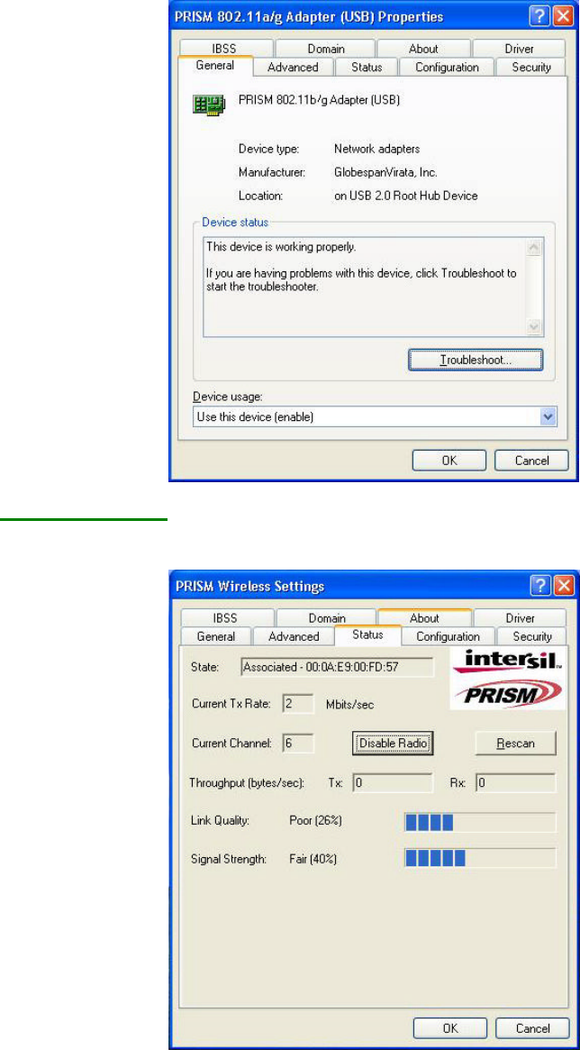
The General Tab
This tab reveals brief information on the 802.11 g/b WLAN USB Stick device itself.
15
The Status Tab
Click the Status tab to appear the following display.
From the window, the general information on the status of currently connected entry
is presented. You may want to click the Rescan button to reinitiate the scanning
process and update the status. Later the result of scanning will be renewed and
displayed in the window. If you wish to stop the networking connection, click the
Disable Radio button to stop scanning. However, if you are already in the disabled
radio mode, you will find the Enable Radio button here instead. Click Enable Radio

16
to regain the link then.
State
Here displays the MAC Address of the current associated entry, which could be a
connected access point in the Access Point mode or computers joining in the
Peer-to-Peer network.
Current Tx Rate
This feature indicates the transmission rate of the current connection.
Current Channel
Here reveals the current channel operated in the wireless network. Note that the
channel number differs as the radio scans any available channels in the Peer-to-Peer
mode.
Throughout (bytes/sec)
This feature indicates the rates of transmitting (Tx) and receiving (Rx) data of your
WLAN USB 802.11 g/b WLAN USB Stick within a short period of time; thus, the
values vary on a time basis.
Link Quality
Link Quality is based on the percentage of successfully transmitted or received
signal of the associated access point beacon within a limited period. The higher the
percentage, the better the link quality. The bar graph beside also provides a visual
interpretation of the current link quality. It is noted that the Link Quality and
Signal Strength features only apply to the Infrastructure mode. They are
inapplicable in the Peer-to-Peer mode since data will be transferred from many
different computers.
Signal Strength
You may learn the received signal strength of the baseband processor of the beacon
signal from the Signal Strength bar beside, and it’s also presented in terms of
percentage. As the signal gets stronger, the signal percentage rate gets higher. It is
noted that the Signal Strength and Link Quality features only apply to the Access
Point mode. They are inapplicable in the Peer-to-Peer mode since data will be
transferred from many different computers.
The IBSS Tab
If you, as a creator of the wireless network, are communicating with other stations via
the IBSS mode to form Peer-to-Peer networks, click the IBSS (Independent Basic
Service Set) tab to specify an operating radio frequency channel from the pull-down
list under the IBSS Channel Selection section.

17
Note that the available channels differ from country to country, and the channel
number must be the same between the entries/stations within the range, so that each
can communicate with each other.
To let the new configuration take effect, please choose Apply.
On the other hand, while in the Access Point mode, you will find the channel number
is the same as the associated access point. Thus, there’s no need to manually set the
value.
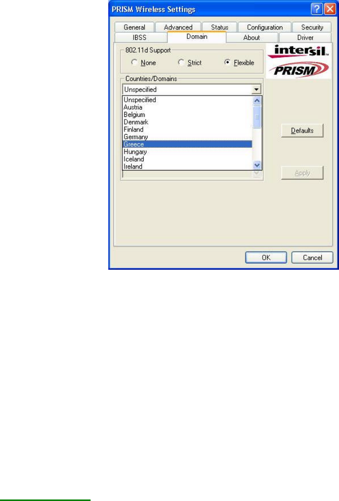
The Domain Tab
While in the 2.4GHz range, the network operation may differ from country to country,
or domain to domain. This is because the 802.11d protocol was established. To have
the operation normally processed, choose the Domain tab to change relevant settings.
18
802.11d Support
802.11d Support lets you operate multi-country roaming. To automatically adjust
regulatory domain while operating network in different countries, choose either
Strict or Flexible according to your need. If you choose None, the task will be
terminated.
Countries/Domains
Define the regulatory domain from the drop-down menu of this command
according to the country you are located in. More detailed information about the
defined country/domain will be listed below afterwards.
When you are done, remember to click Apply to let the new settings take effect.
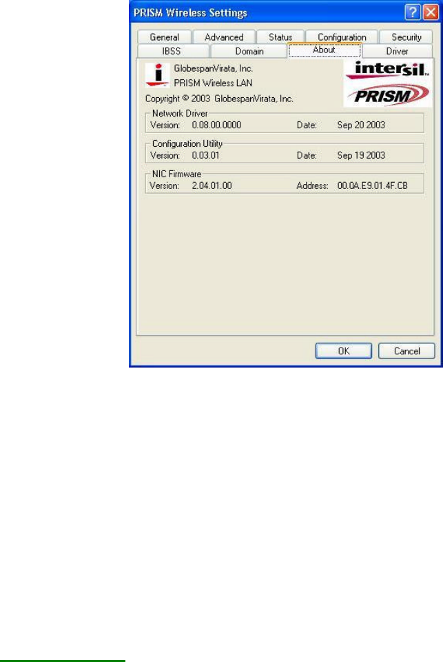
The About Tab
This tab reveals general information on your 802.11 g/b WLAN USB Stick, including
the following items:
19
Network Driver
Displays the current version and released date of the 802.11 g/b WLAN USB
Stick’s driver.
Configuration Utility
Displays the current version and released date of the attached configuration tool.
NIC Firmware
Displays the current NIC card firmware version and the MAC (Media Access
Control) address of your wireless card. It is consisted of 12-digit hexadecimal
numbers (48 bits in length) to identify your computer's physical address on the
local area network.
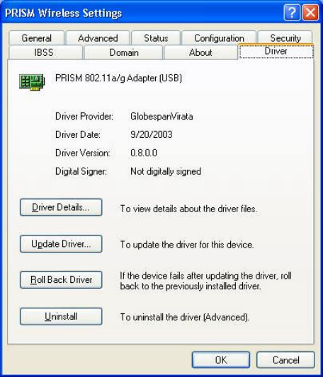
The Driver Tab
This tab provides you various commands used on the 802.11 g/b WLAN USB Stick’s
driver.
20