Arcadyan Technology WN7911A 2.4GHZ SDIO Sip Module User Manual WN7911A LF manual BVADT
Arcadyan Technology Corporation 2.4GHZ SDIO Sip Module WN7911A LF manual BVADT
UserManual.wiki
>
Arcadyan Technology
>
WN7911A User Manual
User Manual.pdf
Navigation menu
Upload a User Manual
Namespaces
Wiki Guide
HTML
PDF
Info
Views
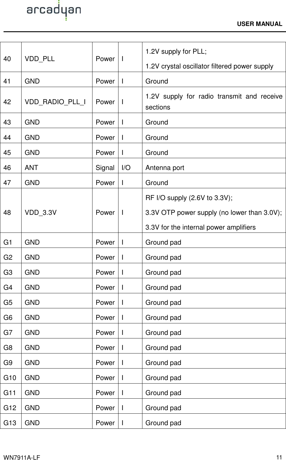
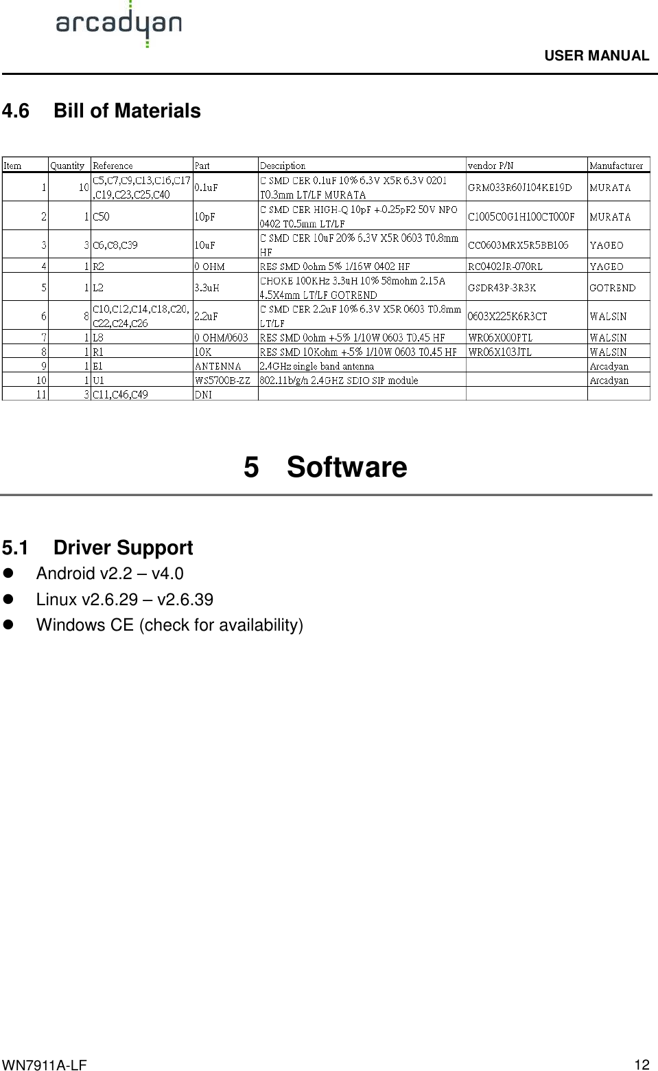
User Manual
Discussion / Help
Navigation