Arcwave AR315500 AR3155 Integrated Subscriber Transceiver User Manual PI 020301 T
Arcwave, Inc. AR3155 Integrated Subscriber Transceiver PI 020301 T
UserManual.wiki
>
Arcwave
>
AR315500 User Manual
USer Manual
Navigation menu
Upload a User Manual
Namespaces
Wiki Guide
HTML
PDF
Info
Views
User Manual
Discussion / Help
Navigation
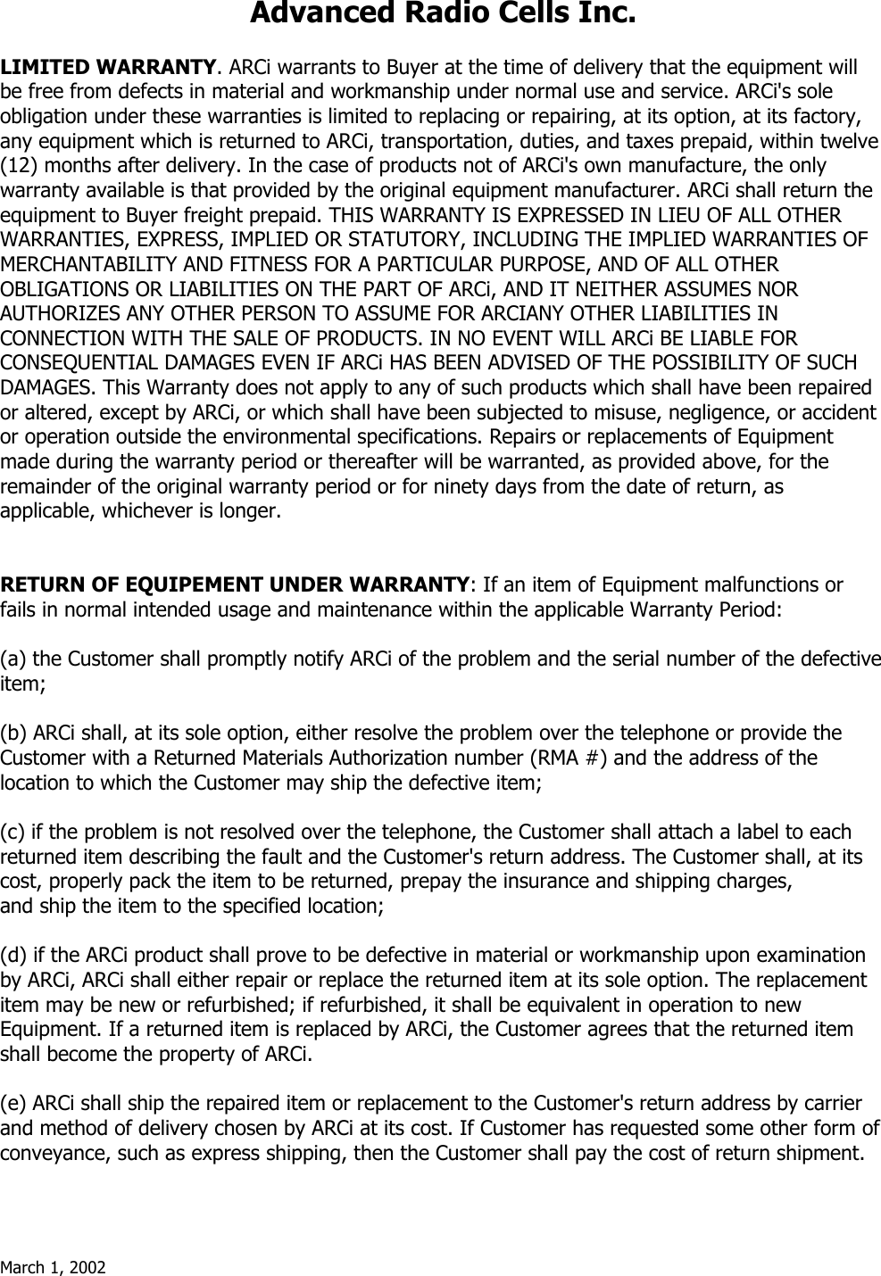


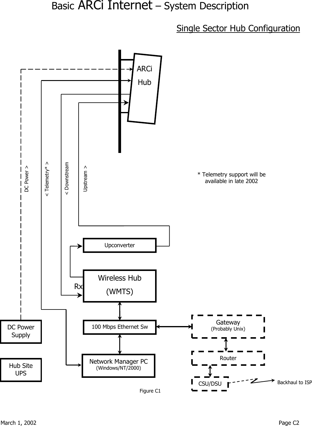
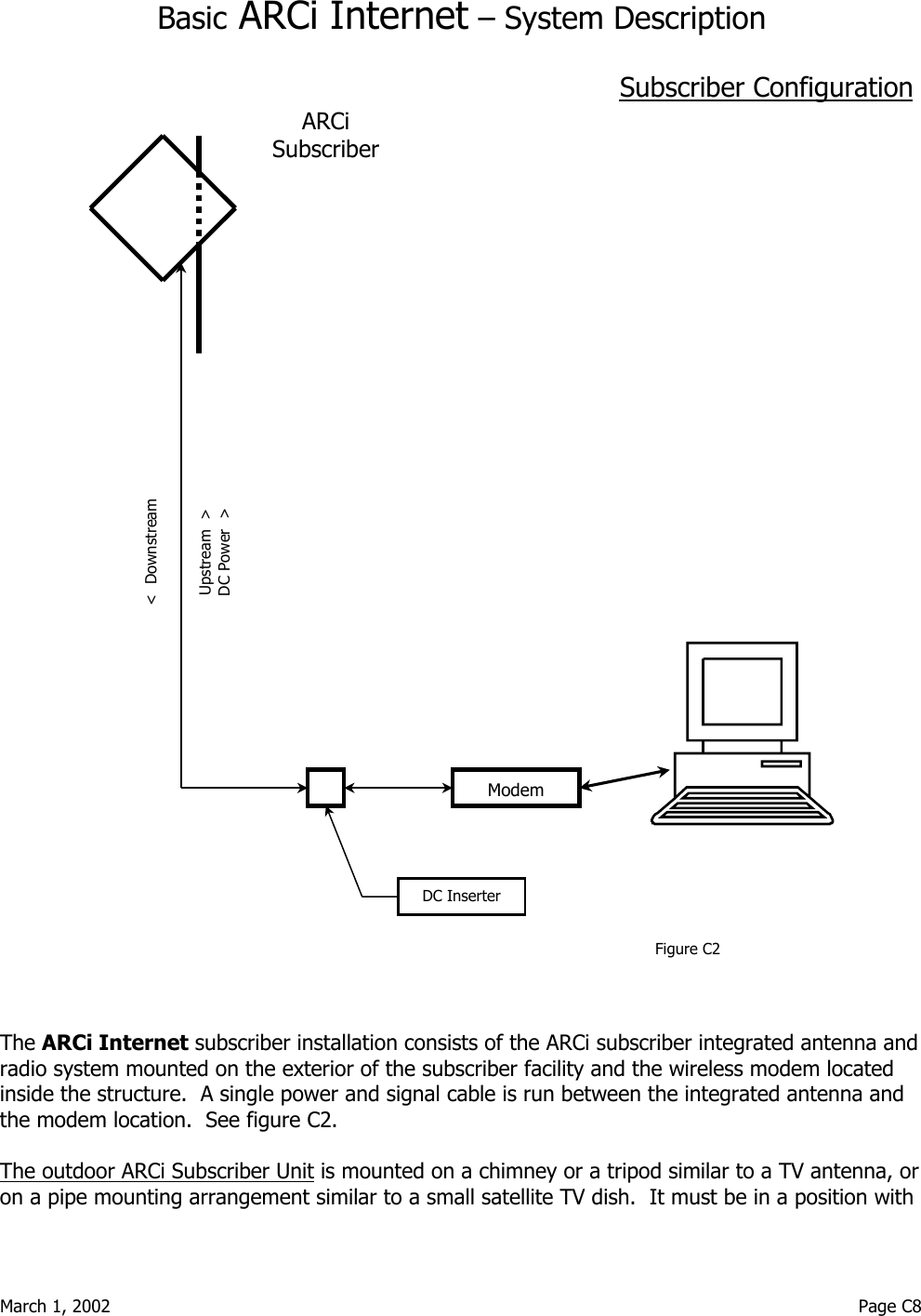
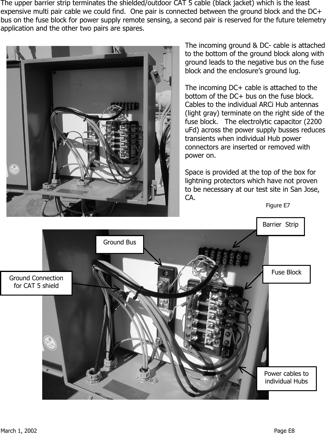
![March 1, 2002 Page C5 Hub Interfaces Industry standard interfaces are employed between the various elements of the Hub system. Refer to Figure 2. Note that specific manufacturer and part numbers are given in the Installation Details section of this manual. See also the ARCi and Vyyo specifications sections of this manual. ARCi Hub Antenna Transmit and receive signal interfaces: 75 ohm type F female connectors Premium quad-shielded RG-6 coax cable recommended (e.g. Belden 1189A) Upstream signal frequency 6.4 through 32 MHz, nominal signal level -4 dBmV. Maximum cable loss between ARCi hub and WMTS: 15 dB at 30 MHz. Downstream signal frequency 477 through 577 MHz, nominal signal level 50 dBmV. Maximum cable loss between upconverter and ARCi hub: 15 dB at 500 MHz. Power interface: Switchcraft type EN3 6 pin male connector on both upstream and downstream radio enclosures (two per hub antenna) Nominal 8.5 Vdc at 920 +/- 100 mA, combined upstream and downstream Telemetry: RS-485, implemented in same connector as power interface on both upstream and downstream radio enclosures. [Telemetry support will be available in late 2002]. Wireless Hub (WMTS) 75 ohm type F female connectors Upstream input signal frequency 6.4 through 32 MHz, nominal signal level -4 dBmV. Downstream output signal frequency 44 MHz, nominal signal level 20 dBmV. (input to Upconverter) Network connection RJ45 female connector, 100 Mbps 100baseT Ethernet LAN](https://usermanual.wiki/Arcwave/AR315500/User-Guide-229709-Page-13.png)
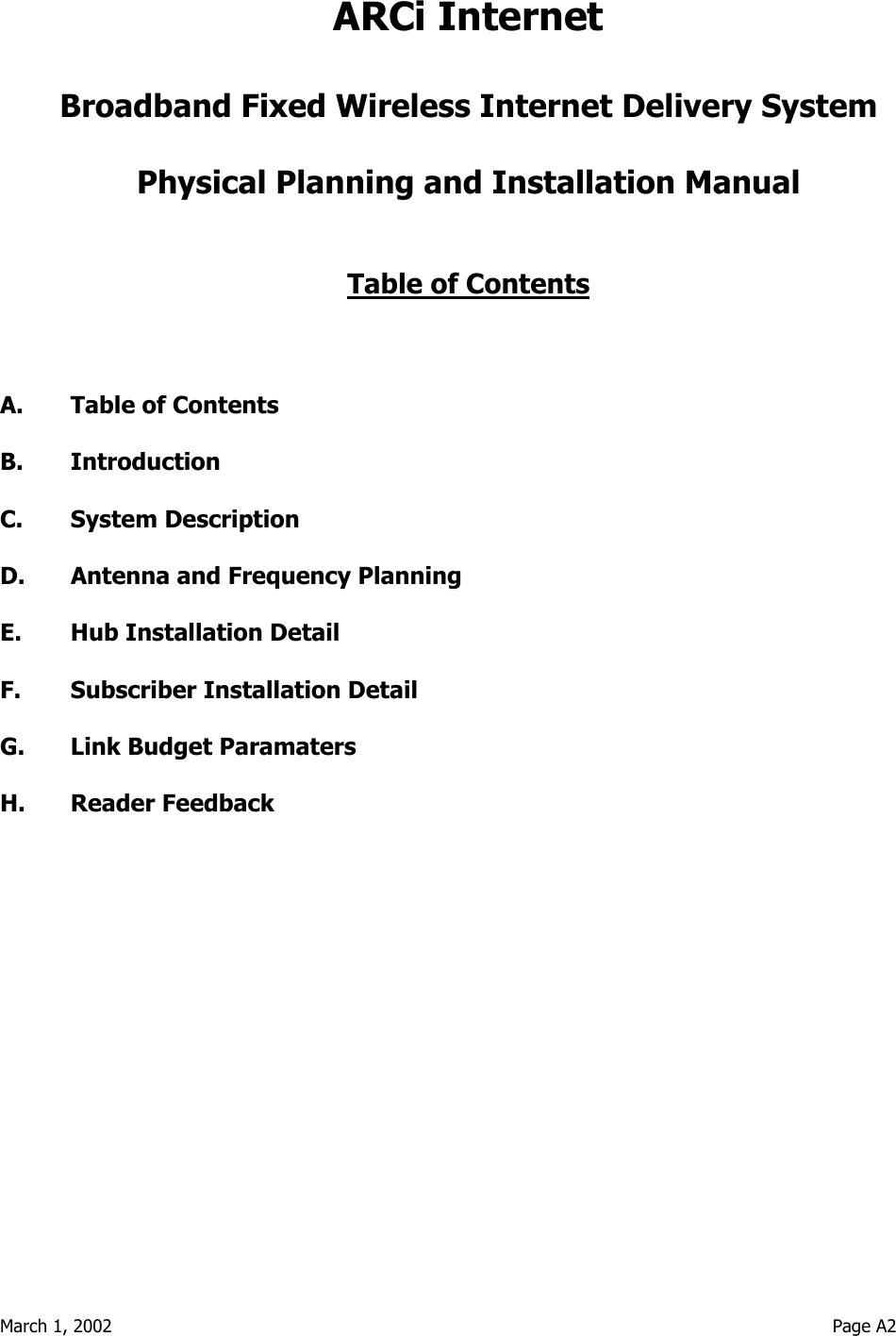
![March 1, 2002 Page C6 Upconverter 75 ohm type F female connectors Input signal frequency 44 MHz; level range +38 dBmV to +45 dBmV. Output signal frequency 477 through 577 MHz; maximum signal level +60 dBmV. 100 Mbps Ethernet Switch The Ethernet switch is the connection point for all TCP/IP data flow on the ARCi Internet side of the gateway (subnet). Subscriber traffic flows through the Gateway to the Internet via the Switch, as does Network Management traffic to and from the WMTS and the Internet. Other devices such as a laptop computer can be plugged into the switch provided that they are configured with the proper TCP/IP addresses for the system subnet. Network Manager PC The network manager PC provides services to the ARCi Internet system such as DHCP, TFTP, SysLog and time servers. It also provides remote operational visibility and control into the ARCi Internet via SNMPc. Note that with appropriate address translation in the Gateway, the Network Manager may be installed at a remote location such as the ISP’s control center. See the Vyyo V3000 Wireless Hub Users’ Manual for more detail. The network manager PC also monitors certain parameters of the transmitter(s) and receiver(s) located within the associated ARCi hubs. It also enables upstream frequency selection for each hub receiver. [Telemetry support for this function will be available in late 2002].. Gateway / Router / Backhaul This equipment provides functions required to interface the ARCi Internet system to the backhaul transmission facility to the ISP, which will normally specify and configure this equipment. It interconnects with the ARCi Internet system via a standard port on the 100 Mbps Ethernet switch. Some notes on the gateway Once it is configured and running, the ARCi wireless network is simply a standalone IP network that requires the presence of a gateway through which packets are routed between the ARCi network and the Internet. The network interface on the ARCi side of the gateway must be 100baseT Ethernet. The gateway itself is typically one of two types depending on the network IP address:](https://usermanual.wiki/Arcwave/AR315500/User-Guide-229709-Page-14.png)

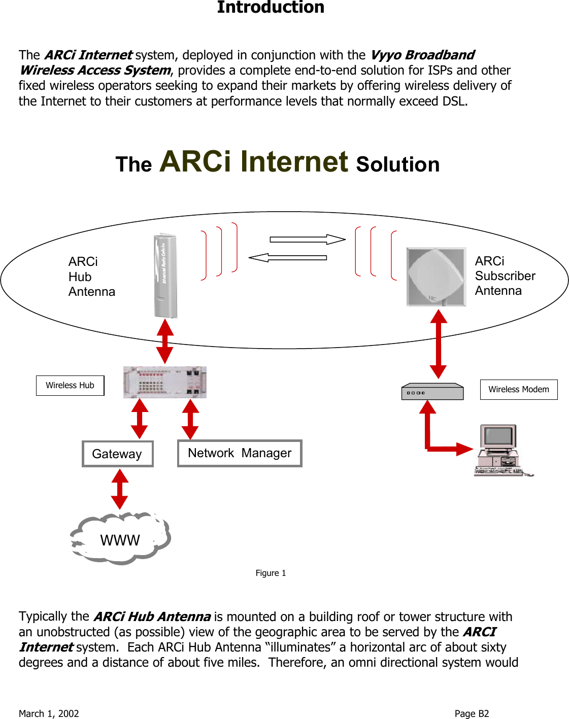
![March 1, 2002 Page D5 Frequency Planning - Upstream Available Channels There are 3 available upstream channels4 when channel bandwidth of 3.2 MHz is employed5. See Table D2. When configuring the system the user must select the upper or lower carrier as well at the modem transmit frequency. The WMTS commands the modem to its upstream transmit frequency during the modem registration process. [The frequency of each upstream channel in a WMTS is set via a parameter of the regtree.txt file in the network management system. See the software installation guide]. All modems utilizing a given upstream channel must transmit on the same frequency, and each modem can operate on only one upstream channel. Notes: 1. These frequencies are subject to change. 4 Additional upstream frequencies will be available in 2002. 5 Contact the factory when upstream channels bandwidths of 400 KHz, 800 KHz or 1.6 MHz are to be utilized. U.S. FCC-approved systems must employ 3.2 MHz upstream bandwidth. Table D2 - ARCi Upstream Frequency Plan Upstream Data Rate 5.12 Mbps; Channel Bandwidth 3.2 MHz Modem Tx Upper Carrier Up WMTS Rx Lower Carrier Low WMTS Rx center (MHz) center (MHz) center (MHz) center (MHz) center (MHz) 6.4 5306.4 6.4 5293.6 6.4 9.6 5309.6 9.6 5290.4 9.6 12.8 5312.8 12.8 5287.2 12.8](https://usermanual.wiki/Arcwave/AR315500/User-Guide-229709-Page-22.png)

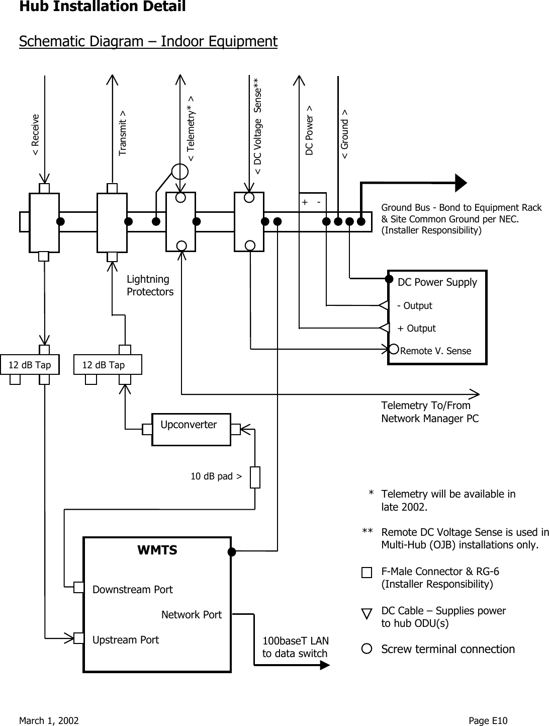
![March 1, 2002 Page E12 In a single sector installation a small variable voltage linear DC power supply capable of supplying at least 1000 mA is employed. ARCi has successfully tested the following power supply in the single sector configuration: Agilent E3610A The voltage (IR) drop of the power cable is calculated and the output of the DC supply is set appropriately. For Example: If a single ARCi hub is connected with a 100 ft. 18 AWG power cable (and the ground (DC-) connection is sufficiently good so as to present negligible resistance - as it should be), the voltage drop equals (0.95 A x 0.69 ohms/100 ft. x 100 ft.) = 0.66 volts. Set the power supply for (8.5 + 0.66 =) 9.2 Volts. In a multi-sector installation the DC power supply is chosen with sufficient capacity to deliver at least 1000 mA for each ARCi hub antenna. The DC+ lead is sized to provide reasonable voltage drop between the DC supply and the Outdoor Junction Box (OJB) installed near the hub antennas. A DC voltage sense pair is installed to sample the DC voltage at the distribution bus in the OJB and provide the sample to the DC supply. The DC power supply is then adjusted to provide 8.5 Vdc at the OJB. [The OJB will be available in mid-2002]. ARCi has successfully tested the following power supply in the multi-sector configuration: [To be determined]. Telemetry Telemetry is a low speed RS-485 signal implemented on a twisted pair between the hub antenna and the network manager computer in the equipment room. In a multi-hub installation, the telemetry connections are simply paralleled at the telemetry terminal strip in the OJB. [Telemetry will be available in late 2002]. DC Sense and Telemetry Cabling ARCi has found that shielded outdoor service rated Category 5 data cable is inexpensive, and two of its four pairs can be utilized for telemetry and DC voltage sense. A cable of this type is Superior Essex BBDN part #04-001-34, which utilizes Hubbell Shield Bond Connectors BC285SB (box 100) + tool BCTK. Transmit (Downstream) Signal Path The downstream signal from the WMTS is connected to the upconverter that is normally mounted in the rack with the WMTS. A 10 dB pad4 is inserted at the input to the upconverter to set the proper level. 4 ARCi will supply one 10 dB pad and two 12 dB taps with each hub. RG6 coaxial cable and connectors are to be supplied by the installer.](https://usermanual.wiki/Arcwave/AR315500/User-Guide-229709-Page-35.png)

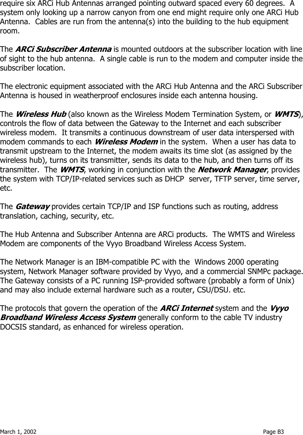
![March 1, 2002 Page F5 DC Power Supply and Inserter Inside the building, route the RG-6 from the building entrance point to the modem location. Attach an F connector and connect it to the “TO AMPLIFIER” or “TO ANTENNA” F female connector on the power inserter. Depending on the version, the wall mounted DC power supply may: - be permanently connected to the inserter as shown in Figure F4, left, or - connect to the inserter with a small DC plug and jack, or - be an F connector lead to the “12 VDC IN” connector on the power inserter. [In the F-connector case, ARCi will supply a 12-inch F-male-to-F-male cable to connect to the power supply. The installer may choose to furnish a longer cable based on the installation specifics]. Modem (WMU) Place the modem where it will be used and attach the short cable on the power inserter (labeled “TO TV” or “TO MODEM” – see Figure F6) to the F connector on the rear of the modem. Connect (the separate) modem wall mounted power supply (included with the modem) to the power connector on the rear of the modem. Plug both wall mounted power supplies into suitable AC power sources – preferably a UPS or surge protected power strip. Connect a straight-through 10BaseT LAN cable between the RJ-45 jack on the modem and the user hub, router or personal computer. Figure F4 Power Inserter and DC Power Supply Figure F5 Power Inserter DetailTo ModemTo Antenna](https://usermanual.wiki/Arcwave/AR315500/User-Guide-229709-Page-44.png)