Arcwave AR315500 AR3155 Integrated Subscriber Transceiver User Manual PI 020301 T
Arcwave, Inc. AR3155 Integrated Subscriber Transceiver PI 020301 T
Arcwave >
USer Manual

March 1, 2002
ARCi Internet
Broadband Fixed Wireless Internet Delivery
System
Physical Planning and Installation Manual
AR1255 Integrated Headend Transceiver
AR3155 Integrated Subscriber Transceiver
© 2001-2002 by Advanced Radio Cells Inc.
Other product and company names mentioned herein may be the trademarks of their respective
owners.
This publication may include technical inaccuracies or typographical errors. Changes are
periodically made to the information herein; these changes will be incorporated in new editions of
this publication. ARCi may make improvements and/or changes in the product(s) described in
this publication at any time.
March 2002
March 1, 2002
Advanced Radio Cells Inc.
LIMITED WARRANTY. ARCi warrants to Buyer at the time of delivery that the equipment will
be free from defects in material and workmanship under normal use and service. ARCi's sole
obligation under these warranties is limited to replacing or repairing, at its option, at its factory,
any equipment which is returned to ARCi, transportation, duties, and taxes prepaid, within twelve
(12) months after delivery. In the case of products not of ARCi's own manufacture, the only
warranty available is that provided by the original equipment manufacturer. ARCi shall return the
equipment to Buyer freight prepaid. THIS WARRANTY IS EXPRESSED IN LIEU OF ALL OTHER
WARRANTIES, EXPRESS, IMPLIED OR STATUTORY, INCLUDING THE IMPLIED WARRANTIES OF
MERCHANTABILITY AND FITNESS FOR A PARTICULAR PURPOSE, AND OF ALL OTHER
OBLIGATIONS OR LIABILITIES ON THE PART OF ARCi, AND IT NEITHER ASSUMES NOR
AUTHORIZES ANY OTHER PERSON TO ASSUME FOR ARCIANY OTHER LIABILITIES IN
CONNECTION WITH THE SALE OF PRODUCTS. IN NO EVENT WILL ARCi BE LIABLE FOR
CONSEQUENTIAL DAMAGES EVEN IF ARCi HAS BEEN ADVISED OF THE POSSIBILITY OF SUCH
DAMAGES. This Warranty does not apply to any of such products which shall have been repaired
or altered, except by ARCi, or which shall have been subjected to misuse, negligence, or accident
or operation outside the environmental specifications. Repairs or replacements of Equipment
made during the warranty period or thereafter will be warranted, as provided above, for the
remainder of the original warranty period or for ninety days from the date of return, as
applicable, whichever is longer.
RETURN OF EQUIPEMENT UNDER WARRANTY: If an item of Equipment malfunctions or
fails in normal intended usage and maintenance within the applicable Warranty Period:
(a) the Customer shall promptly notify ARCi of the problem and the serial number of the defective
item;
(b) ARCi shall, at its sole option, either resolve the problem over the telephone or provide the
Customer with a Returned Materials Authorization number (RMA #) and the address of the
location to which the Customer may ship the defective item;
(c) if the problem is not resolved over the telephone, the Customer shall attach a label to each
returned item describing the fault and the Customer's return address. The Customer shall, at its
cost, properly pack the item to be returned, prepay the insurance and shipping charges,
and ship the item to the specified location;
(d) if the ARCi product shall prove to be defective in material or workmanship upon examination
by ARCi, ARCi shall either repair or replace the returned item at its sole option. The replacement
item may be new or refurbished; if refurbished, it shall be equivalent in operation to new
Equipment. If a returned item is replaced by ARCi, the Customer agrees that the returned item
shall become the property of ARCi.
(e) ARCi shall ship the repaired item or replacement to the Customer's return address by carrier
and method of delivery chosen by ARCi at its cost. If Customer has requested some other form of
conveyance, such as express shipping, then the Customer shall pay the cost of return shipment.
March 1, 2002
Advanced Radio Cells Inc.
Broadband Fixed Wireless Internet Delivery System
Physical Planning and Installation Manual
Entire Contents Copyright 2001-2002
Advanced Radio Cells Inc.
910 Campisi Way, Suite 1F
Campbell, CA 95008
USA
Phone: 408-558-2760
888-863-8225
FAX: 408-371-7584
www.arcells.com

March 1, 2002 Page A1
A. Table of Contents

March 1, 2002 Page A2
ARCi Internet
Broadband Fixed Wireless Internet Delivery System
Physical Planning and Installation Manual
Table of Contents
A. Table of Contents
B. Introduction
C. System Description
D. Antenna and Frequency Planning
E. Hub Installation Detail
F. Subscriber Installation Detail
G. Link Budget Paramaters
H. Reader Feedback

March 1, 2002 Page B1
B. Introduction
Ctt
March 1, 2002 Page B2
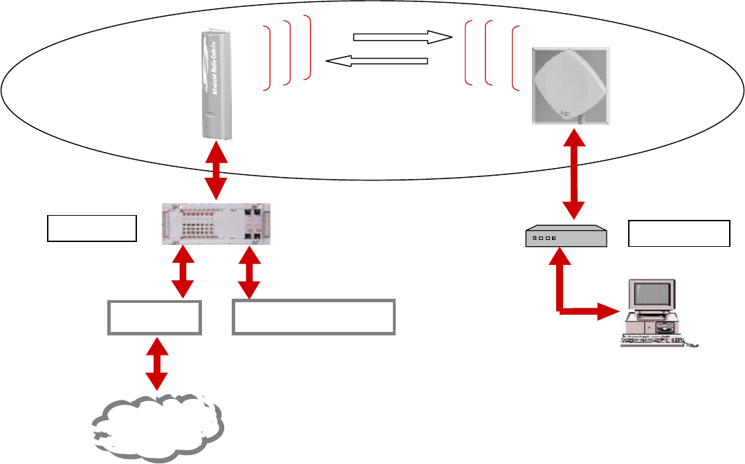
Introduction
The
ARCi Internet
system, deployed in conjunction with the
Vyyo Broadband
Wireless Access System
, provides a complete end-to-end solution for ISPs and other
fixed wireless operators seeking to expand their markets by offering wireless delivery of
the Internet to their customers at performance levels that normally exceed DSL.
Figure 1
Typically the
ARCi Hub Antenna
is mounted on a building roof or tower structure with
an unobstructed (as possible) view of the geographic area to be served by the
ARCI
Internet
system. Each ARCi Hub Antenna “illuminates” a horizontal arc of about sixty
degrees and a distance of about five miles. Therefore, an omni directional system would
Hub
Antenna
Hub Cable
Modem
ARCi
Subscriber
Antenna
WWW
Wireless Modem
Wireless Hub
The ARCi Internet Solution
ARCi
Gateway Network Manager
March 1, 2002 Page B3
require six ARCi Hub Antennas arranged pointing outward spaced every 60 degrees. A
system only looking up a narrow canyon from one end might require only one ARCi Hub
Antenna. Cables are run from the antenna(s) into the building to the hub equipment
room.
The
ARCi Subscriber Antenna
is mounted outdoors at the subscriber location with line
of sight to the hub antenna. A single cable is run to the modem and computer inside the
subscriber location.
The electronic equipment associated with the ARCi Hub Antenna and the ARCi Subscriber
Antenna is housed in weatherproof enclosures inside each antenna housing.
The
Wireless Hub
(also known as the Wireless Modem Termination System, or
WMTS
),
controls the flow of data between the Gateway to the Internet and each subscriber
wireless modem. It transmits a continuous downstream of user data interspersed with
modem commands to each
Wireless Modem
in the system. When a user has data to
transmit upstream to the Internet, the modem awaits its time slot (as assigned by the
wireless hub), turns on its transmitter, sends its data to the hub, and then turns off its
transmitter. The
WMTS
, working in conjunction with the
Network Manager
, provides
the system with TCP/IP-related services such as DHCP server, TFTP server, time server,
etc.
The
Gateway
provides certain TCP/IP and ISP functions such as routing, address
translation, caching, security, etc.
The Hub Antenna and Subscriber Antenna are ARCi products. The WMTS and Wireless
Modem are components of the Vyyo Broadband Wireless Access System.
The Network Manager is an IBM-compatible PC with the Windows 2000 operating
system, Network Manager software provided by Vyyo, and a commercial SNMPc package.
The Gateway consists of a PC running ISP-provided software (probably a form of Unix)
and may also include external hardware such as a router, CSU/DSU. etc.
The protocols that govern the operation of the
ARCi Internet
system and the
Vyyo
Broadband Wireless Access System
generally conform to the cable TV industry
DOCSIS standard, as enhanced for wireless operation.

March 1, 2002 Page C1
C. System Description
March 1, 2002 Page C2
< Downstream
U
p
stream >
< Telemetr
y
* >
DC Power >
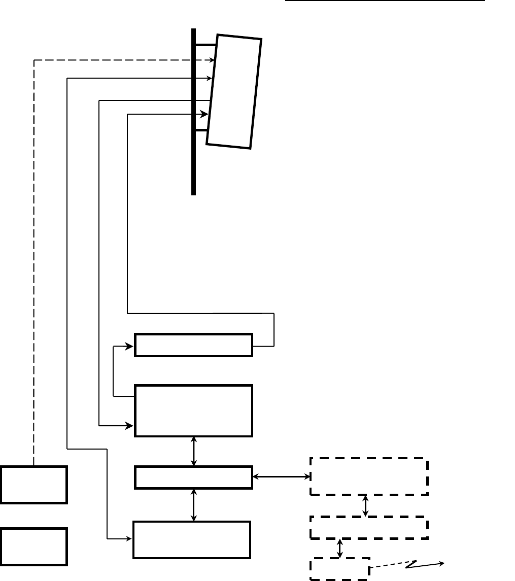
Basic ARCi Internet – System Description
Single Sector Hub Configuration
Rx
Figure C1
Hub Site
UPS
DC Power
Supply
Wireless Hub
(WMTS)
Backhaul to ISP
Upconverter
ARCi
Hub
Network Manager PC
(Windows/NT/2000)
100 Mbps Ethernet Sw Gateway
(Probably Unix)
Router
CSU/DSU
* Telemetry support will be
available in late 2002

March 1, 2002 Page C3
Basic ARCi Internet – System Description
Single Sector Hub Configuration
The ARCi Internet hub location consists of one or more ARCi Hub Antennas mounted on the
building roof or adjacent tower or monopole structure and its associated equipment located in the
interior hub equipment room. Signal and power cables are run from the hub antenna(s) to the
hub equipment room. See figure C1 on the preceding page.
The outdoor ARCi Hub Antenna is mounted on a vertical pipe or tower leg, aimed at the
geographic area to be served. As each hub antenna covers a sector (arc) about 60 degrees wide,
from one to six hub antennas are required depending on the desired coverage. Each hub
antenna requires its own upstream, downstream and power connection to the hub equipment
room.
Refer to the
Frequency/Coverage Planning
section of this manual for the details of antenna
coverage and frequency utilization.
The
Installation Details
section provides mounting information, test access and system grounding
recommendations for the antenna and wireless hub.
The
ARCi Specifications
section provides dimension, weight and mounting details.
Located in the equipment room are:
1. Wireless Hub and its network manager system
2. Downstream Upconverter
3. 100 Mbps Ethernet switch
4. Gateway system
5. Router and ISP access equipment
6. Uninterruptible power supply system (UPS) to protect all hub equipment
7. DC power supply for the hub antenna electronics
The Wireless Hub (WMTS), Upconverter and Network Manager components are purchased from
ARCi or directly from Vyyo, Inc.
The Gateway and ISP access equipment are selected and configured according to the
requirements of the particular ISP and the backhaul facility between the hub site and the ISP
facilities.
The customer also must provide a DC power supply with sufficient capacity to operate the radio
equipment. The UPS is strongly-recommended to protect system operation throughout short
outages, as well as to provide isolation between incoming power line anomalies and the hub
electronic equipment. See the
Hub Installation Details
section of this manual.

March 1, 2002 Page C4
Basic ARCi Internet – System Description
Multi-Sector Hub Configuration
The Multi-Sector configuration consists of two or more ARCi Hub antennas mounted on a
common building roof or tower/monopole structure served by a single Wireless Hub (WMTS)
located in an adjacent equipment room.
As each Hub antenna covers a sector sixty degrees wide, six ARCi Hub antennas are required for
complete 360-degree coverage. Fewer Hub antennas may be required depending on the
relationship of the Hub site to the geography to be covered by the system.
Each hub requires a separate Upstream and Downstream IF cable, so a six sector (six ARCi Hub)
installation would require 12 IF coaxial cables. Refer to figure C1. The DC power and telemetry
cables are simply paralleled in a multi-sector configuration. This can be accomplished by running
separate power/telemetry cables from each ARCi Hub antenna to the equipment room, or by
installing an Outdoor Junction Box (OJB) on the mounting structure adjacent to the Hub antennas
and paralleling the DC power and telemetry in the OJB.
See the
Hub Installation Details
section of this manual for more information.

March 1, 2002 Page C5
Hub Interfaces
Industry standard interfaces are employed between the various elements of the Hub system.
Refer to Figure 2. Note that specific manufacturer and part numbers are given in the
Installation
Details
section of this manual. See also the ARCi and Vyyo specifications sections of this manual.
ARCi Hub Antenna
Transmit and receive signal interfaces:
75 ohm type F female connectors
Premium quad-shielded RG-6 coax cable recommended (e.g. Belden 1189A)
Upstream signal frequency 6.4 through 32 MHz, nominal signal level -4 dBmV.
Maximum cable loss between ARCi hub and WMTS: 15 dB at 30 MHz.
Downstream signal frequency 477 through 577 MHz, nominal signal level 50 dBmV.
Maximum cable loss between upconverter and ARCi hub: 15 dB at 500 MHz.
Power interface:
Switchcraft type EN3 6 pin male connector on both upstream and downstream radio
enclosures (two per hub antenna)
Nominal 8.5 Vdc at 920 +/- 100 mA, combined upstream and downstream
Telemetry:
RS-485, implemented in same connector as power interface on both upstream and
downstream radio enclosures. [Telemetry support will be available in late 2002].
Wireless Hub (WMTS)
75 ohm type F female connectors
Upstream input signal frequency 6.4 through 32 MHz, nominal signal level -4 dBmV.
Downstream output signal frequency 44 MHz, nominal signal level 20 dBmV. (input to
Upconverter)
Network connection RJ45 female connector, 100 Mbps 100baseT Ethernet LAN

March 1, 2002 Page C6
Upconverter
75 ohm type F female connectors
Input signal frequency 44 MHz; level range +38 dBmV to +45 dBmV.
Output signal frequency 477 through 577 MHz; maximum signal level +60 dBmV.
100 Mbps Ethernet Switch
The Ethernet switch is the connection point for all TCP/IP data flow on the ARCi Internet
side of the gateway (subnet).
Subscriber traffic flows through the Gateway to the Internet via the Switch, as does
Network Management traffic to and from the WMTS and the Internet. Other devices such
as a laptop computer can be plugged into the switch provided that they are configured
with the proper TCP/IP addresses for the system subnet.
Network Manager PC
The network manager PC provides services to the ARCi Internet system such as DHCP,
TFTP, SysLog and time servers. It also provides remote operational visibility and control
into the ARCi Internet via SNMPc. Note that with appropriate address translation in the
Gateway, the Network Manager may be installed at a remote location such as the ISP’s
control center. See the Vyyo V3000 Wireless Hub Users’ Manual for more detail.
The network manager PC also monitors certain parameters of the transmitter(s) and
receiver(s) located within the associated ARCi hubs. It also enables upstream frequency
selection for each hub receiver. [Telemetry support for this function will be available in
late 2002]..
Gateway / Router / Backhaul
This equipment provides functions required to interface the ARCi Internet system to the
backhaul transmission facility to the ISP, which will normally specify and configure this
equipment. It interconnects with the ARCi Internet system via a standard port on the
100 Mbps Ethernet switch.
Some notes on the gateway
Once it is configured and running, the ARCi wireless network is simply a standalone IP
network that requires the presence of a gateway through which packets are routed
between the ARCi network and the Internet. The network interface on the ARCi side of the
gateway must be 100baseT Ethernet. The gateway itself is typically one of two types
depending on the network IP address:

March 1, 2002 Page C7
If the network IP address is registered with its country’s Network Information Center then
the gateway may be nothing more than a conventional router.
If, on the other hand, the network IP address is one of the RFC1597 private addresses the
gateway must be a proxy server of some sort. For example, the gateway may provide
RFC1631 Network Address Translation services.
Additional security measures such as firewalls may be added at the customer’s
option.
DC Power Supply
The DC power supply is located in the equipment room and supplies DC power to operate
all of the ARCi hubs in the installation. In a single sector hub configuration a single power
cable is furnished which has two power connectors on the outside end1 and is run along
with the signal cables from the hub antenna to the equipment room. In a multi-sector
hub configuration separate power/telemetry cables can be run to the equipment room
from each ARCi Hub, or an Outdoor Junction Box (OJB) can be installed in the vicinity of
the hub antennas (rooftop / tower structure) and a single appropriately sized cable run to
the equipment room. See the
Hub Installation Details
section of this manual for more
information.
The electronics in the hub antenna are designed to function with a DC voltage at the hub
nominally 8.5 Vdc +/- 0.5 V.
In a single sector hub the voltage drop on the power cable is calculated and the DC power
supply voltage is set in the equipment room. The current drawn by a single hub (both
transmitter and receiver) is 950 mA +/- 10%.
In a multi-sector hub where an OJB is employed, the power supply remote sense samples
the DC voltage at the distribution terminals within the OJB and returns the sample to the
DC power supply via the DC power sense cable.
See the
Hub Installation Details
section of this manual for more information on
recommended power supplies
1 Within a given ARCi hub antenna, the transmit and receive electronics are housed in separate inner
enclosures and have separate power connectors.
March 1, 2002 Page C8
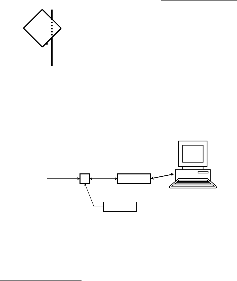
Basic ARCi Internet – System Description
Subscriber Configuration
The ARCi Internet subscriber installation consists of the ARCi subscriber integrated antenna and
radio system mounted on the exterior of the subscriber facility and the wireless modem located
inside the structure. A single power and signal cable is run between the integrated antenna and
the modem location. See figure C2.
The outdoor ARCi Subscriber Unit is mounted on a chimney or a tripod similar to a TV antenna, or
on a pipe mounting arrangement similar to a small satellite TV dish. It must be in a position with
Modem
DC Inserter
ARCi
Subscriber
Upstream >
DC Power >
< Downstream
Fi
g
ure C2

March 1, 2002 Page C9
line of sight to the hub location. At the time of installation the antenna is carefully aimed to
transmit and receive to/from the hub.
The
Subscriber Installation Details
section provides mounting information and grounding
recommendations for the integrated antenna.
The
ARCi Specifications
section provides dimension, weight and mounting details.
Inside the Subscriber Location, the wireless modem is connected to the PC by means of a
standard Ethernet LAN cable. Alternatively a LAN hub or switch may be employed between the
modem and the PC(s), as the modem has a gateway function that will support up to 15 PCs2
sharing the modem. A small DC inserter device is connected between the modem and the lead to
the outdoor unit. The inserter has a cord mounted power supply (wall wart) as does the modem.
Subscriber Interfaces
See also the ARCi and Vyyo specifications section of this manual.
ARCi Integrated Antenna
The data transmit and receive signals as well as the DC power share a common cable with an
ARCi proprietary electrical interface. Connections are:
75 ohm type F female connector
Quality dual-shielded RG-6 coax cable recommended (e.g. Belden 9116)
Wireless Modem
75 ohm type F female connector to DC inserter and integrated antenna
Data connection RJ45 female connector, 10 Mbps standard 10BaseT Ethernet LAN
(straight-through cable to PC)
2 The number of PCs supported by a single modem is 75.

March 1, 2002 Page D1
D. Antenna and
Frequency Planning

March 1, 2002 Page D2
Antenna and Frequency Planning
Antenna Patterns
Horizontal
The ARCi standard hub antenna is moderately directional, transmitting and receiving in a
coverage pattern 60 degrees wide1. This means that the geographic coverage of the antenna is
30 degrees on each side of a line drawn straight out from the front of the antenna. Geography
further to the sides or rear of the antenna receives increasingly less signal.
Therefore, a system where the hub location is roughly in the center of the geography to be
served would probably employ six ARCi hub antennas (each with its own integrated electronics)
aimed 60 degrees apart to complete the circle of coverage. A hub located at one side of the
coverage area might only require 3 hub antennas to provide 180 degrees of geographic coverage.
Vertical
Similarly, the antenna is directional in the vertical plane2. This means that elevations above
straight out from the front of the antenna (up in the sky) receive less power, as do elevations
below straight out. Therefore, the antenna is normally pointed at the furthest subscriber to be
served, with the lower elevations providing appropriately less power to closer subscribers.
Antenna Patterns
See the Antenna Patterns section of this manual for measured plots typical of ARCi antennas.
Other Antenna Configurations
Contact ARCi for other antenna configurations. FCC regulations require that the combination of
the actual power output of the ARCi transmitter and the gain of the antenna
together
do not
exceed specified limits.
Frequency Planning - Downstream
Available Channels
There are 16 available downstream channels in the ARCi standard frequency plan. The
downstream frequency is established by the front panel control of the upconverter. The
displayed frequency on the upconverter (in MHz) is the center of the 6 MHz wide downstream
signal.
1 ARCi’s standard antenna has a so-called “half power beam width”, or “3 dB beam width” of 60 degrees in
the horizontal plane. The ARCi 2001, beta units have 3 dB beam widths of 45 degrees.
2 The 3 dB beam width in the vertical plane is 3 degrees.

March 1, 2002 Page D3
The frequencies displayed in Table D1 were chosen such that the resulting signal as received by
the modem corresponds to a standard EIA CATV channel. This is because the modem, when not
properly initialized or when it has lost track of the downstream signal, will “step” through the
standard EIA channel list looking for a downstream signal. Alternatively, the modem may be
optioned through its administrator interface to lock onto a specific downstream frequency,
removing this requirement.
When the ARCi hub antenna is utilized in an MMDS repeater application its frequency conversion
(from upconverter output to carrier output) can be factory modified3 to meet the requirements of
the MMDS transverter frequency plan. Contact the ARCi factory for more information on
alternative frequency plans.
Table D1 – ARCi Standard Downstream Frequency Plan
Upconverter Carrier Modem Modem
center freq. (MHz) center freq. (MHz) center freq. (MHz) EIA Channel
481 5729 429
58
487 5735 435
59
493 5741 441
60
499 5747 447
61
505 5753 453
62
511 5759 459
63
517 5765 465
64
523 5771 471
65
529 5777 477
66
535 5783 483
67
541 5789 489
68
547 5795 495
69
553 5801 501
70
559 5807 507
71
565 5813 513
72
571 5819 519
73
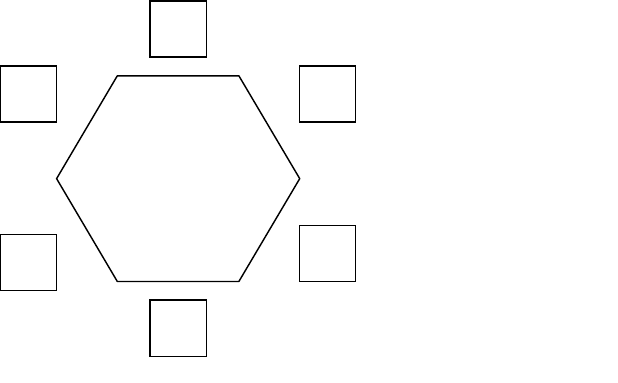
Adjacent Sectors
The ARCi standard hub antenna has been described above as having a half power horizontal
beam width of 60 degrees. But, the energy of the antenna does not simply cut off at 30 degrees
in horizontal pattern from the centerline of the antenna. Rather, the energy falls off as the angle
from the centerline increases. This means that a subscriber in the vicinity of 30 degrees
clockwise from antenna A will also be in the vicinity of 30 degrees counterclockwise from adjacent
antenna B. Subscribers in the overlap zone – especially if they are relatively close to the hub –
will receive downstream signals from both adjacent hub antennas. This will cause unacceptable
3 The ARCi subscriber unit has a fixed conversion that cannot be modified.
March 1, 2002 Page D4
interference if both hub antennas are transmitting on the same frequency, even though the
subscriber is receiving nominally the same signal from both hub antennas.
The solution for this is to ensure that adjacent hub antennas are never transmitting on the same
frequency. A minimum of two frequencies (and a maximum of six frequencies) is required for an
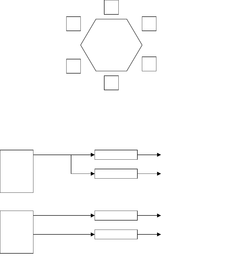
omnidirectional system employing six – 60 degree hub antennas. See Figure D1, following.
In a 10 Mbps hub, one WMTS downstream signal is utilized and two upconverters output the
same signal on frequency A and frequency B. In a 20 Mbps hub, two WMTS downstream signals
are utilized, each driving a separate upconverter A and upconverter B. A 30 Mbps hub can be
created by utilizing three upconverters in an ABCABC pattern. See figure D2.
A
B
A
B
B
A
Omnidirectional
Hub
6 sectors
Figure D1
WMTS U
p
converter A
U
p
converter B
A
Antennas
B Antennas
10 Mb
p
s Hub
–
One Downstream
WMTS U
p
converter A
U
p
converter B
A
Antennas
B Antennas
20 Mb
p
s Hub
–
Two Downstreams
Figure D2
Downstream Channel
Example

March 1, 2002 Page D5
Frequency Planning - Upstream
Available Channels
There are 3 available upstream channels4 when channel bandwidth of 3.2 MHz is employed5. See
Table D2. When configuring the system the user must select the upper or lower carrier as well at
the modem transmit frequency. The WMTS commands the modem to its upstream transmit
frequency during the modem registration process. [The frequency of each upstream channel in a
WMTS is set via a parameter of the
regtree.txt
file in the network management system. See the
software installation guide]. All modems utilizing a given upstream channel must transmit on the
same frequency, and each modem can operate on only one upstream channel.
Notes:
1. These frequencies are subject to change.
4 Additional upstream frequencies will be available in 2002.
5 Contact the factory when upstream channels bandwidths of 400 KHz, 800 KHz or 1.6 MHz are to be
utilized. U.S. FCC-approved systems must employ 3.2 MHz upstream bandwidth.
Table D2 - ARCi Upstream Frequency Plan
Upstream Data Rate 5.12 Mbps; Channel Bandwidth 3.2 MHz
Modem Tx Upper Carrier Up WMTS Rx Lower Carrier Low WMTS Rx
center (MHz) center (MHz) center (MHz) center (MHz) center (MHz)
6.4 5306.4 6.4 5293.6 6.4
9.6 5309.6 9.6 5290.4 9.6
12.8 5312.8 12.8 5287.2 12.8
March 1, 2002 Page D6
Omnidirectional
Hub
6 sectors
Generally each upstream channel will terminate in a separate upstream port of the WMTS. WMTS
upstream port cards are available in single and six input configurations. Thus, a typical six sector
omnidirectional hub would utilize a single six input WMTS upstream card. See Figure D3,
following.
This omnidirectional system might pair downstream channel A (Figure D1) with upstream channel
G (Figure 5), etc. See Table D3 for this example.
Table D3 – Sector Example
Downstream Upstream
Sector Channel Channel
North A I
NE B G
SE A H
South B I
SW A G
NW B H
I
G
H
I
H
G
Figure D3
Upstream Channel
Example

March 1, 2002 Page E1
E. Hub Installation
Detail
March 1, 2002 Page E2
< Receive
Transmit >
DC Power &
T
elemetry < >
Hub Installation Detail
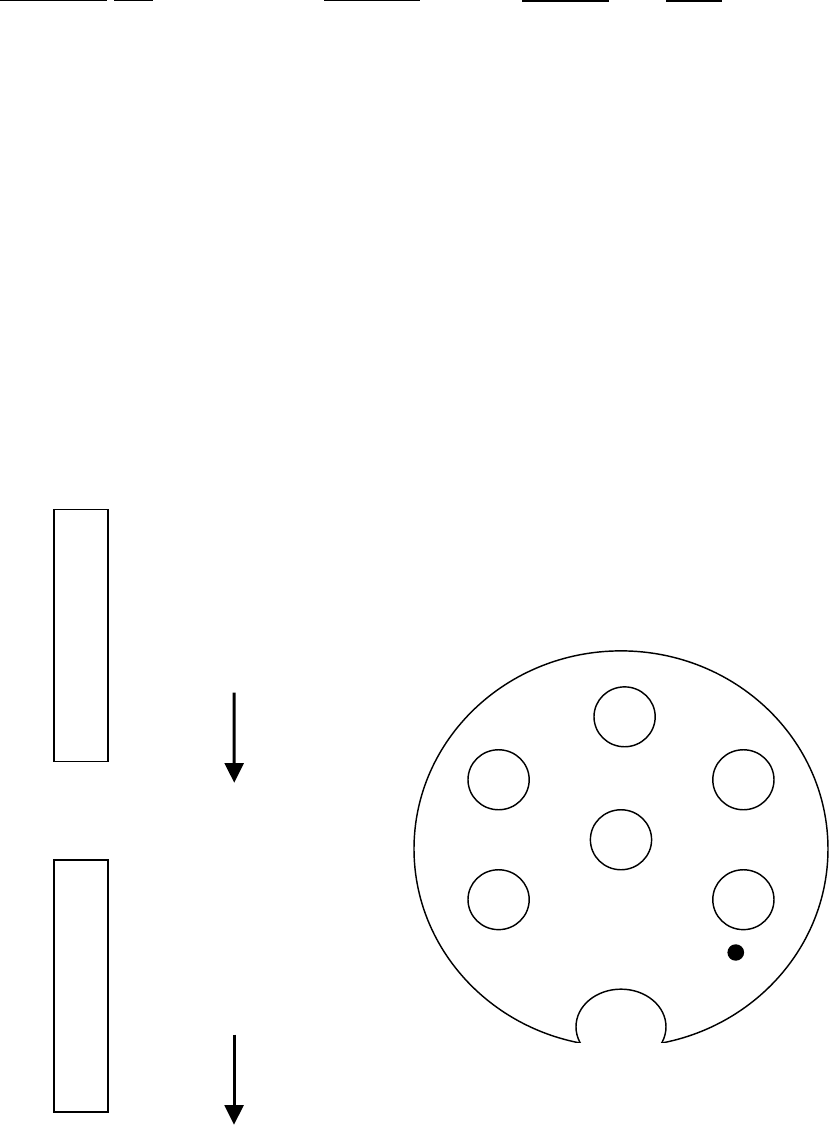
Schematic Diagram – Outdoor Unit
F-Male Connector & RG-6
(Installer Responsibility)
DC & Telemetry Connectorized
Cable (Included with Hub)
Receive
Ground Hub to
Supporting Structure
or Building Steel per
NEC or Local Code
Note: Rear weather cap must
be in place and all screws
secured for outdoor installation.

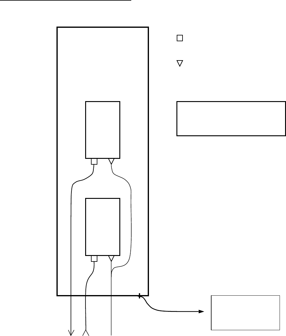
March 1, 2002 Page E3
Hub Installation Detail
Installation Detail – Outdoor Unit (ODU)
Cable connections
It will be more convenient to connect the ODU cables and close the headend rear weather cap
prior to attaching the ODU to its mounting pipe. Refer to the Schematic Diagram – Outdoor
Unit on the previous page.
Remove the sixteen screws securing the rear weather cap to the anodized aluminum back plate
of the antenna, taking care not to damage the gasket around the weather cap. This will reveal
two aluminum housings containing the ARCi outdoor electronics1. The upper housing contains
the receiver and the lower the transmitter. Note the F-female and power/telemetry2 connectors
on the bottom of each.
Attach the receive (upstream) RG-6 to the F connector on the upper electronics housing and
the transmit (downstream) RG-6 to the F connector on the lower electronics housing. ARCi
recommends the use of premium quad-shielded RG-6 coaxial cable (such as Belden 1189A) for
headend installations.
Attach the ARCi-provided power/telemetry “Y” cable to the connectors on both electronics
housings (connectors are interchangeable). Note that the power/telemetry connector is keyed
and must be rotated into the correct position prior to seating. The locking ring is quite stiff and
must be turned approximately ¼ turn clockwise for proper connection. Be sure that the
upstream and downstream RG-6 and the power/telemetry cables clear the mounting screw
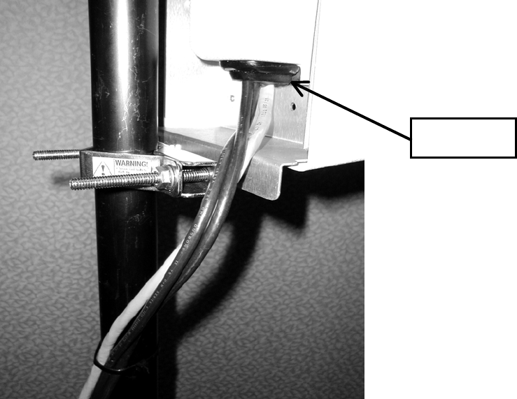
holes for the rear weather cap. Refer to the photograph in Figure E1. Dress the cables as
shown in the photograph and secure with a tie-wrap below the lower electronics housing.
Although the power/telemetry connectors are interchangeable, the method illustrated in the
photograph will produce best results.
It is not necessary to disturb the SMA coaxial connector on the top of each electronics housing.
This is the connection to the actual antenna panel.
Replace the headend rear weather cap taking care that the gasket is seated smoothly around
the edge of the weather cap and that the three cables pass through the cable access on the
bottom end of the weather cap. Replace the sixteen screws securing the weather cap snugly
but not tightly enough to distort the gasket. See Figure E2.
1 Complete replacement of one or both of the aluminum housings containing the electronic assemblies is the only
user service possible for the ARCi headend ODU.
2 The pin connection information is detailed on the last page of this chapter – it is not normally needed as ARCi
supplies the power/telemetry cable.
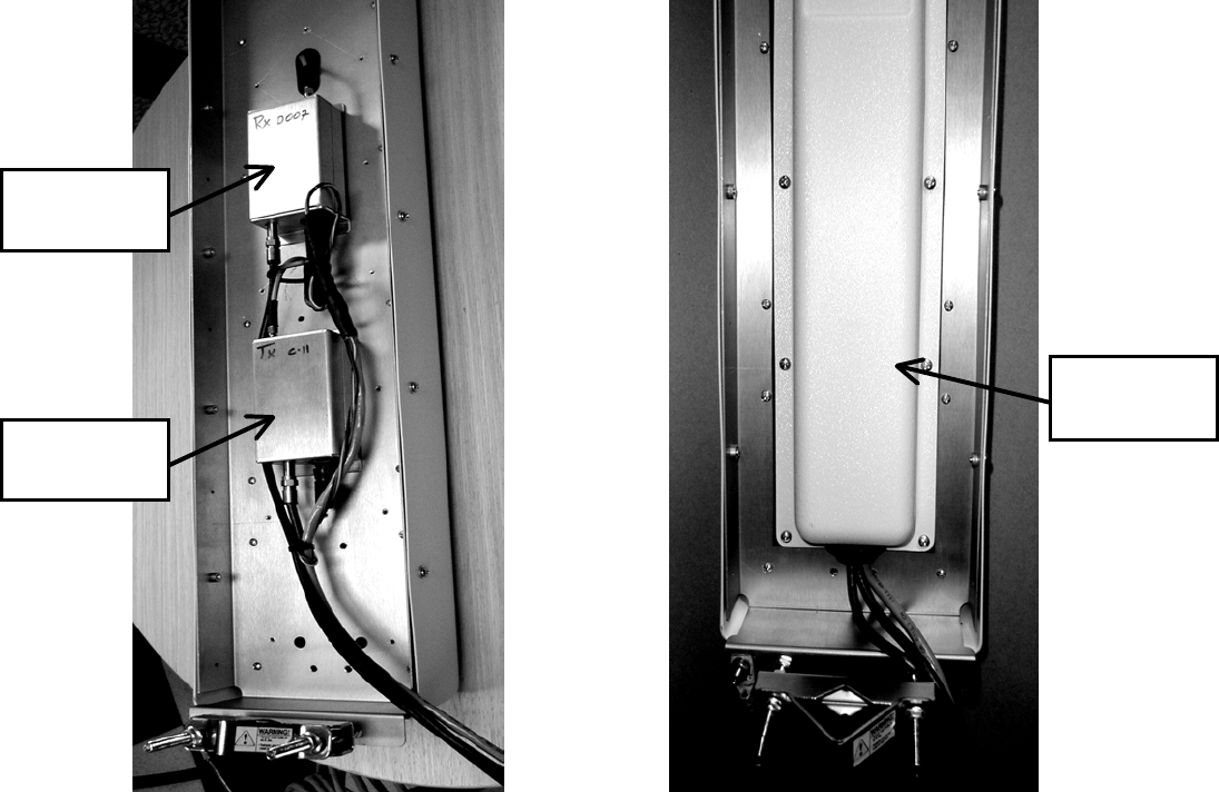
March 1, 2002 Page E4
Mounting
Mount the ARCi ODU on a vertical pipe with at least 44 vertical inches clear of unrelated
hardware or other impediments. The ODU mounting brackets will accommodate pipe from 1.5
to 2.25 inches in outside diameter. Up-tilt or down-tilt is accomplished by means of adjusting
the nuts on the 5/16 inch threaded bolts captive to the mounting assembly. See Figure E3 for
details.
Figure E1 Cable Installation and Dressing Figure E2 Weather Cap Installed
Receiver
(Upstream)
Transmitter
(Downstream)
Rear
Weather Cap
March 1, 2002 Page E5
Figure E3 ODU Bracket Detail
Ground the antenna to the metallic mounting structure (tower or monopole) or suitable rooftop
ground point per local codes and installation practices. Normally #6 AWG or larger wire is
utilized for this purpose. A ¼-20 ground bolt is provided on the bottom flange of the ODU
assembly to attach the ground wire3. This is illustrated in Figure E3.
Bundle the three cables (2 x RG-6, power/telemetry) with suitable (UV rated) tie wraps and
secure to the mounting structure in a manner to prevent rainwater from flowing down the cable
and into the cable access opening in the rear weather cap. Figure E4 illustrates a typical
installation. Be certain to provide a drip loop of cable bundle is routed upward.
In the case of a single sector, single ARCi headend installation, route the bundle of three cables
to the hub indoor equipment room. Take care to leave suitable drip loops and bond the shields
of the RG-6 and power/telemetry cables to ground per local codes and installation practices.
If the hub site is multi-sector (two or more collocated ARCi hub ODUs), route the bundle of
three cables to the ARCi outdoor junction box (OJB). Refer to the
OJB Schematic Diagram and
Installation Details
.
3 In the very early beta versions of the ARCi ODU the ground bolt is not present. In that case, the ground lead can
be attached to the 5/16 inch mounting bolt.
Ground Lead
March 1, 2002 Page E6
Figure E4 Hub Antenna and Cable Installation
Cable Access
March 1, 2002 Page E7
Hub Installation Detail
Installation Detail – Outdoor Junction Box (OJB)
The Multi-Sector configuration consists of two or more ARCi Hub antennas mounted on a common
building roof or tower/monopole structure served by a single Wireless Hub (WMTS) located in an
adjacent equipment room.
Each hub requires a separate Upstream and Downstream IF cable, so a six sector (six ARCi Hub)
installation would require 12 IF coaxial cables. The DC power and telemetry cables are simply
paralleled in a multi-sector configuration. This can be accomplished by running separate
power/telemetry cables from each ARCi Hub antenna to the equipment room, or by installing an
Outdoor Junction Box (OJB) on the mounting structure adjacent to the Hub antennas and paralleling the
DC power and telemetry in the OJB.
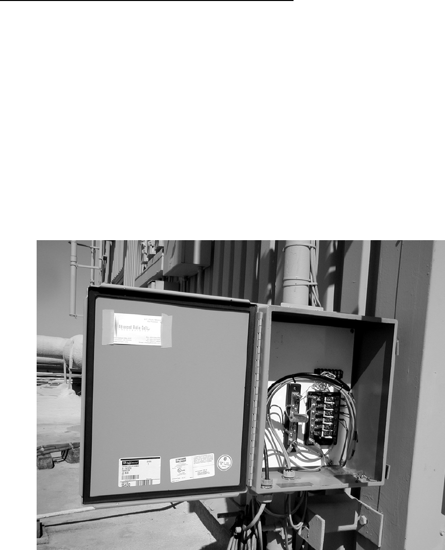
Implementation
Pictured below (Figure E5) is ARCi’s implementation of an OJB as its test site.
Figure E5
March 1, 2002 Page E8
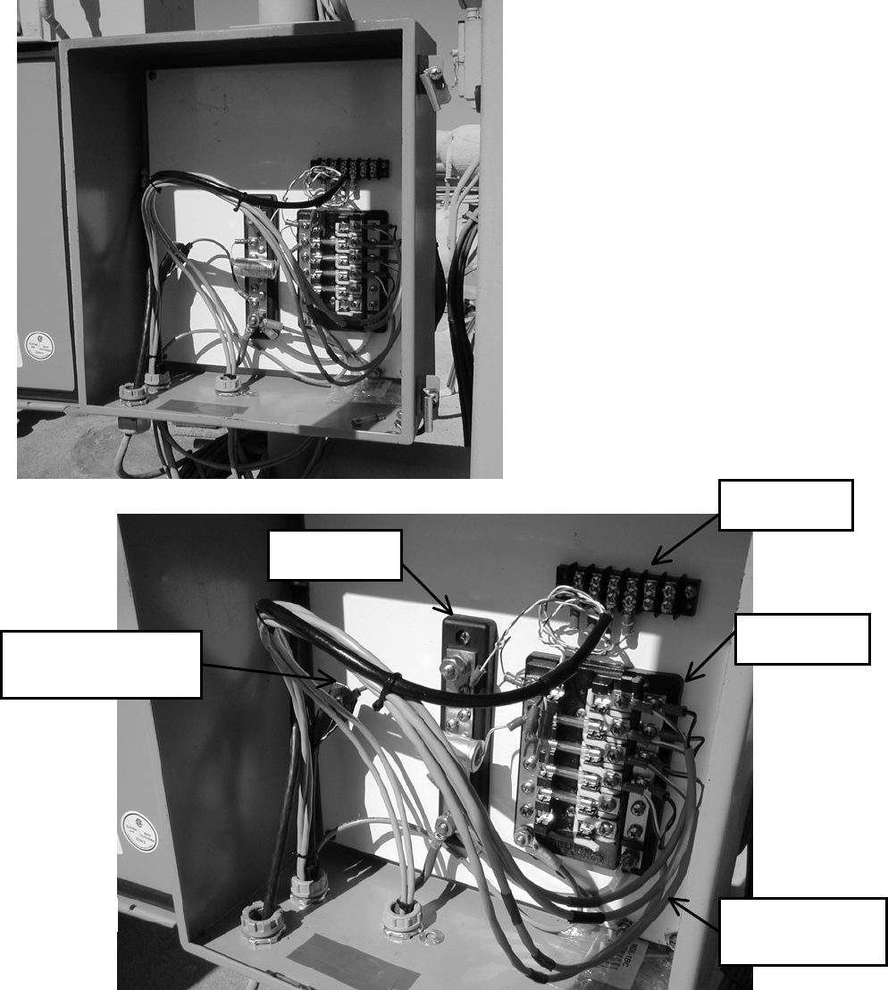
The upper barrier strip terminates the shielded/outdoor CAT 5 cable (black jacket) which is the least
expensive multi pair cable we could find. One pair is connected between the ground block and the DC+
bus on the fuse block for power supply remote sensing, a second pair is reserved for the future telemetry
application and the other two pairs are spares.
The incoming ground & DC- cable is attached
to the bottom of the ground block along with
ground leads to the negative bus on the fuse
block and the enclosure’s ground lug.
The incoming DC+ cable is attached to the
bottom of the DC+ bus on the fuse block.
Cables to the individual ARCi Hub antennas
(light gray) terminate on the right side of the
fuse block. The electrolytic capacitor (2200
uFd) across the power supply busses reduces
transients when individual Hub power
connectors are inserted or removed with
power on.
Space is provided at the top of the box for
lightning protectors which have not proven
to be necessary at our test site in San Jose,
CA.
Figure E7
Fuse Bloc
k
Ground Bus
Ground Connection
for CAT 5 shield
Power cables to
individual Hubs
Barrier Strip

March 1, 2002 Page E9
OJB Components
The OJB pictured here is assembled from the following components:
Device Vendor & Part Number Source
Enclosure Hoffman A-1412CH Electric Supply Trade www.hoffmanonline.com
Inner Panel Hoffman A14P12
Fuse Block Blue Sea Systems 5015 West Marine Retail www.bluesea.com
Ground Bus Blue Sea Systems 2301
Dual Bus (use in lieu of fuse block or for telemetry paralleling)
Blue Sea Systems 2702
Rubber Insert ¾” couplings, locknuts, bushings Electric Supply Trade
Shielded Cat 5 Cable Superior Essex BBDN Part #04-001-34 Graybar Electric
Cat 5 Shield Bond Connectors Hubbell BC285SB Graybar Electric
March 1, 2002 Page E10
< Receive
10 dB pad >
T
ransmit >
DC Power >
< Telemetry* >
< DC Voltage Sense**
< Ground >
+ -
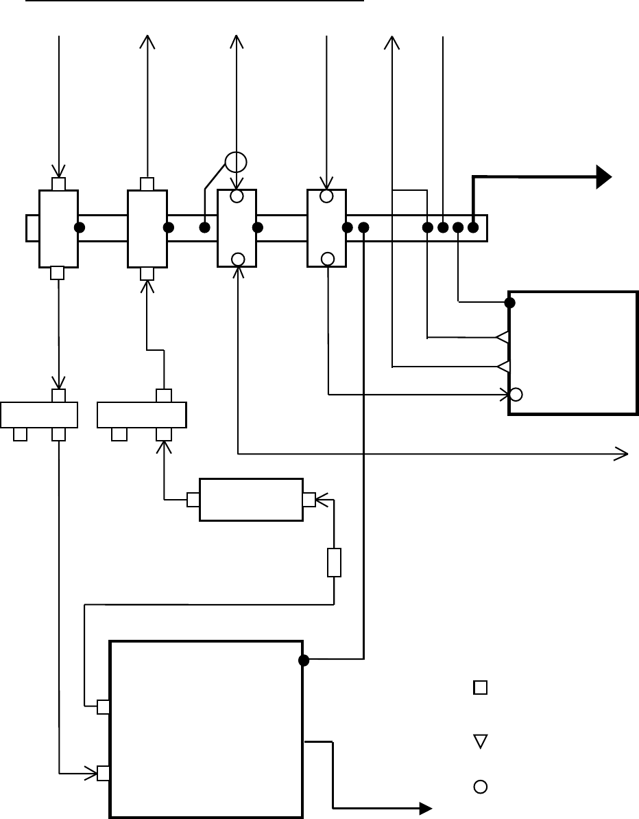
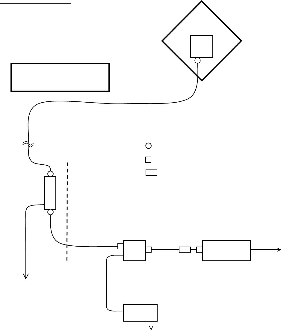
Hub Installation Detail
Schematic Diagram – Indoor Equipment
Ground Bus - Bond to Equipment Rack
& Site Common Ground per NEC.
(Installer Responsibility)
Lightning
Protectors
Telemetry To/From
Network Manager PC
* Telemetry will be available in
late 2002.
** Remote DC Voltage Sense is used in
Multi-Hub (OJB) installations only.
F-Male Connector & RG-6
(Installer Responsibility)
DC Cable – Supplies power
to hub ODU(s)
Screw terminal connection
Upconverter
WMTS
Downstream Port
Network Port
Upstream Port
12 dB Ta
p
12 dB Ta
p
DC Power Supply
- Output
+ Output
Remote V. Sense
100baseT LAN
to data switch

March 1, 2002 Page E11
Hub Installation Detail
Installation Detail – Indoor Equipment
Grounding
Proper grounding is critical to the safety, performance and the life of the equipment installed at
the hub. Refer to the
Schematic Diagram – Indoor Equipment
on the preceding page. ARCi
recommends that the installer follow the general grounding practices employed in cellular and PCS
hub sites.
ARCi recommends the following Lightning Protectors from PolyPhaser Corp.
(www.polyphaser.com). These PolyPhaser devices are designed to be bolted directly to the
ground bus.
75 ohm RG-6 transmit and receive cable IS-75F-C1
Remote DC voltage sense IS-SPDDL
RS-485 telemetry IS-SPHSD
The ground bus, in turn, should be connected with an appropriate conductor (minimum #6 AWG)
to the hub site ground that includes the power service and building common ground, per the NEC
and local codes.
ARCi recommends the installer run a minimum #6 AWG conductor between the equipment room
ground bus and a common ground point adjacent to the hub antenna(s) unless the antenna
mounting system consists of a known low impedance ground (as a steel tower or monopole). In
the case of a single sector ARCi installation, this point can be the antenna ground bolt or
mounting bracket. In a multi sector ARCi installation including an ARCi outdoor junction box
(OJB) this conductor can be connected to the ground bus in the OJB, which in turn, is connected
to each hub antenna and any nearby building or support structure ground.
Normally the WMTS, upconverter(s), DC power supply, 100baseT data switch, etc. are mounted in
a 19-inch equipment rack in the hub equipment room. This rack should also be connected to the
ground bus, preferably by a conductor #6 AWG or greater.
When shielded cable is utilized to connect DC power, voltage sense, and/or telemetry between the
hub equipment room and the hub antenna, ground the shield to the ground bus in the equipment
room.
DC Power
The ARCi hub antenna requires 8.5 Vdc +/- 0.5 volts at the hub antenna and draws approximately
950 mA.

March 1, 2002 Page E12
In a single sector installation a small variable voltage linear DC power supply capable of supplying
at least 1000 mA is employed. ARCi has successfully tested the following power supply in the
single sector configuration:
Agilent E3610A
The voltage (IR) drop of the power cable is calculated and the output of the DC supply is set
appropriately.
For Example
: If a single ARCi hub is connected with a 100 ft. 18 AWG power cable (and
the ground (DC-) connection is sufficiently good so as to present negligible resistance - as
it should be), the voltage drop equals (0.95 A x 0.69 ohms/100 ft. x 100 ft.) = 0.66 volts.
Set the power supply for (8.5 + 0.66 =) 9.2 Volts.
In a multi-sector installation the DC power supply is chosen with sufficient capacity to deliver at
least 1000 mA for each ARCi hub antenna. The DC+ lead is sized to provide reasonable voltage
drop between the DC supply and the Outdoor Junction Box (OJB) installed near the hub antennas.
A DC voltage sense pair is installed to sample the DC voltage at the distribution bus in the OJB
and provide the sample to the DC supply. The DC power supply is then adjusted to provide 8.5
Vdc at the OJB. [The OJB will be available in mid-2002].
ARCi has successfully tested the following power supply in the multi-sector configuration:
[To be determined].
Telemetry
Telemetry is a low speed RS-485 signal implemented on a twisted pair between the hub antenna
and the network manager computer in the equipment room. In a multi-hub installation, the
telemetry connections are simply paralleled at the telemetry terminal strip in the OJB. [Telemetry
will be available in late 2002].
DC Sense and Telemetry Cabling
ARCi has found that shielded outdoor service rated Category 5 data cable is inexpensive, and two
of its four pairs can be utilized for telemetry and DC voltage sense. A cable of this type is
Superior Essex BBDN part #04-001-34, which utilizes Hubbell Shield Bond Connectors BC285SB
(box 100) + tool BCTK.
Transmit (Downstream) Signal Path
The downstream signal from the WMTS is connected to the upconverter that is normally mounted
in the rack with the WMTS. A 10 dB pad4 is inserted at the input to the upconverter to set the
proper level.
4 ARCi will supply one 10 dB pad and two 12 dB taps with each hub. RG6 coaxial cable and connectors are
to be supplied by the installer.
March 1, 2002 Page E13
The upconverter is adjusted to provide the downstream signal at the center frequency appropriate
for the ARCi hub transmitter to create the desired RF carrier frequency. See Table D1 in the
Antenna and Frequency Planning
section of this manual for more information. The output of the
upconverter is connected with RG-6 cables through a 12 dB tap, and thence through the lightning
protector to the cable to the ARCi hub antenna.
The 12 dB taps provide negligible attenuation to the signal passing through and “copy” of the
signal 12 dB lower in level to the tap port. These are utilized for inserting a spectrum analyzer for
system set-up and maintenance without disturbing the normal connections.
Receive (Upstream) Signal Path
The upstream signal from the ARCi hub antenna is connected through the lightning protector and
through the 12 dB tap to the upstream port of the WMTS.

March 1, 2002 Page E14
System Level Setting Notes
General
The head end and subscriber transmitters are designed for linear operation at the maximum output
power allowed for compliant operation under the FCC part 15 regulations. In both the head end
and the subscriber units the input power level to the ARCi radios determines that of the output.
There is no gain adjustment available to the user.
Downstream Power
The head end transmitter power is set by adding fixed attenuators to the downstream IF path,
adjusting the output level of the upconverter, or some combination thereof. The ARCi headend
ODU is factory calibrated to produce a +30 dBm maximum EIRP when this level is applied to the
headend ODU IF input. This is the level required for FCC compliance.
Downstream Power Adjustment Procedure
1. Disconnect the IF cable at the input to the head end ODU transmitter and connect the
cable to the input of a suitably calibrated spectrum analyzer.
2. Set up the spectrum analyzer as follows:
Center Frequency IF frequency in use (481 – 571 MHz)
Span 100 MHz
RBW 1 MHz
VBW 30 KHz
Vertical Scale linear, 10 dB / division
Reference Level +40 dBmV
Attenuation 20 dB
Detection Mode Averaging
3. Adjust the IF level at the upconverter or by inserting fixed attenuators as needed to
ensure that the observed modulation peaks do not exceed +23 dBmV.
4. As an alternative to performing this adjustment at the rear of the headend ODU, it can
be made at the indoor equipment end of the IF cable, as above, if the loss of the cable at
the IF frequency is calculated. The observed modulation peaks can then be adjusted so as
not to exceed (+30 dBmV + loss dB). For example, the loss of typical good quality RG6
cable is 4.57 dB/100 ft. at 550 MHz.

March 1, 2002 Page E15
Upstream Power
The output level of the Cable Modem establishes the subscriber transmitter’s output power. An
automatic feedback loop, controlled by the WMTS, commands each CM to adjust its output level
such that the level of the signal received at the head end is suitable for demodulation by the WMTS.
The user may tune this power control loop by modifying the
UpstreamRxGain
parameter in the
RegTree file. (See Vyyo V3000 Wireless Hub User’s Manual section 7.2). Setting this parameter to 0
will generally yield satisfactory performance.
The ARCi subscriber ODU is factory calibrated to maximum FCC permissible EIRP when the DOCSIS
cable modem is at its maximum power output level.
The most accurate method of setting the actual output power level is to attach an RF power meter
capable of measuring up to 6 GHz to the output of the hub transmitter through a 15 inch long
RG142B/U SMA-SMA cable and then adjusting the IF level until the power indicated on the meter is +15
dBm. However, ARCi does not recommend that this adjustment be made in the field unless under the
direct instruction of the ARCi factory.
Warning! The transmitter must never be operated without a 50 Ω load attached to its
RF output connector. Be sure to remove the DC power from the transmitter prior to
removing the load from the output.
IMPORTANT NOTE: To comply with FCC RF exposure compliance
requirements, antenna installation and device operating configuration
described in this user manual must be satisfied. The antenna(s) used for
this device must be fixed-mounted on outdoor permanent structures with
a separation of at least 1.5 meters from all persons during normal
operation.
March 1, 2002 Page E16
ARCi Hub
Power / Telemetry Cable Convention
Belden EN3/Internal Headers
3124A
Switchcraft EN3 Downlead Twisted 9744
Pin 1 DC Ground* Black Black [ Black
[
2 DC + 8.5 VDC* Red Red [ Red
3 Telemetry + White Yellow [ White
[
6 Telemetry – Green Green [ Black
4 & 5 (reserved)
* ARCi lab standard
Internal Headers
Cord Connector Rear View
(equals)
Panel Connector front View
1
4
3
2
1 5
6
AR105
Rx
●
●
●
●
●
AR150
Tx
●
●
●
●
●
n.c.
+8 Vdc
ground
data -
data +
n.c.
+8 vdc
ground
data +
data -
data +
data -
ground
+8 Vdc
not used
(+5 Vdc)
to
SMA
to
SMA

March 1, 2002 Page F1
F. Subscriber Inst’l
Details
March 1, 2002 Page F2
Subscriber Installation Detail
Schematic Diagram
Subscriber Unit
Rear View
Building
Entrance F-Male connector with waterproofing boot and seal
F-Male connector for interior installation
10 - 20 dB pad may be required < 1 mile from hub
Grounding
Device NOTE:
1. Dual shield RG-6 coaxial cable (Belden 9116 or
equiv.) & F-Male connectors are supplied by installer.
2. Items labeled (inc.) are included with Subscriber Unit
DC Inserter 10baseT LAN
(inc.) cable to PC
Ground typical or hub
of CATV…
NEC 810.2 &
820.33 to 820.42
(Installer Responsibility)
120 VAC
Transformer Cord
DC Power Supply (inc.)
Wireless
Modem
NOTE: Coaxial cable length
between DC Inserter & Outdoor Unit
must be between 50 and 200 feet.
March 1, 2002 Page F3
Subscriber Installation Detail
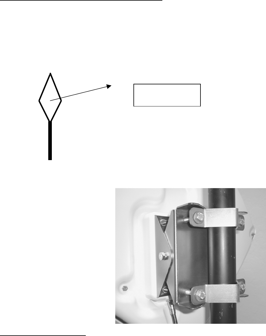
Installation Detail – Subscriber Outdoor Unit
Mounting
Mount the ARCi subscriber outdoor unit (ODU) on a vertical pipe with at least 12 inches clear of
any hardware or other impediments. The mounting brackets will accommodate pipe diameter
from 1.25 to 2 inches. Up-tilt or down-tilt is accomplished by loosening the cap screws on the
sides of the mounting assembly. See Figures F1 and F2. The front face of the antenna must
point in the direction of the system hub and have a clear view of the hub antenna1.
Figure F1 Subscriber ODU Orientation
1 Subscriber installations located close to the hub installation may work successfully through nearby tree
foliage, but this must be verified in the field.
Point center of ODU
towards System Hub
Fi
g
ure F2
Subscriber ODU Mounting
March 1, 2002 Page F4
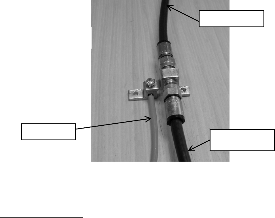
Cable Connection and Grounding
Attach the single RG-6 coaxial cable to the F connector on the rear of the subscriber ODU.
Waterproof the connection using a suitable method such as taping with Scotch #88. Be sure to
leave sufficient slack to allow the antenna to be oriented and that the cable runs directly
downward from the connector to avoid water running down the cable and into the F connection.
Route the coaxial cable to the building entry point utilizing UV-resistant tie-wraps and staples or
cable clamps as required.
Mount the grounding device (e.g. Radio Shack 15-909C) as near as practicable to the point of
cable entry to the structure. See Figure F3. Connect the grounding device to a suitable
“grounding electrode”.2 Connect the RG-6 coaxial cable from the subscriber ODU and the RG-6
that enters the structure to the grounding device and waterproof all exterior F connectors as
described above.
2 The National Electric Code, sections 820-33 and 820-40, describes this requirement in detail.
Figure F3
Grounding device
Ground Lead
T
o CPE Outdoor Unit
To CPE Indoor Unit
(Power Inserter)
March 1, 2002 Page F5
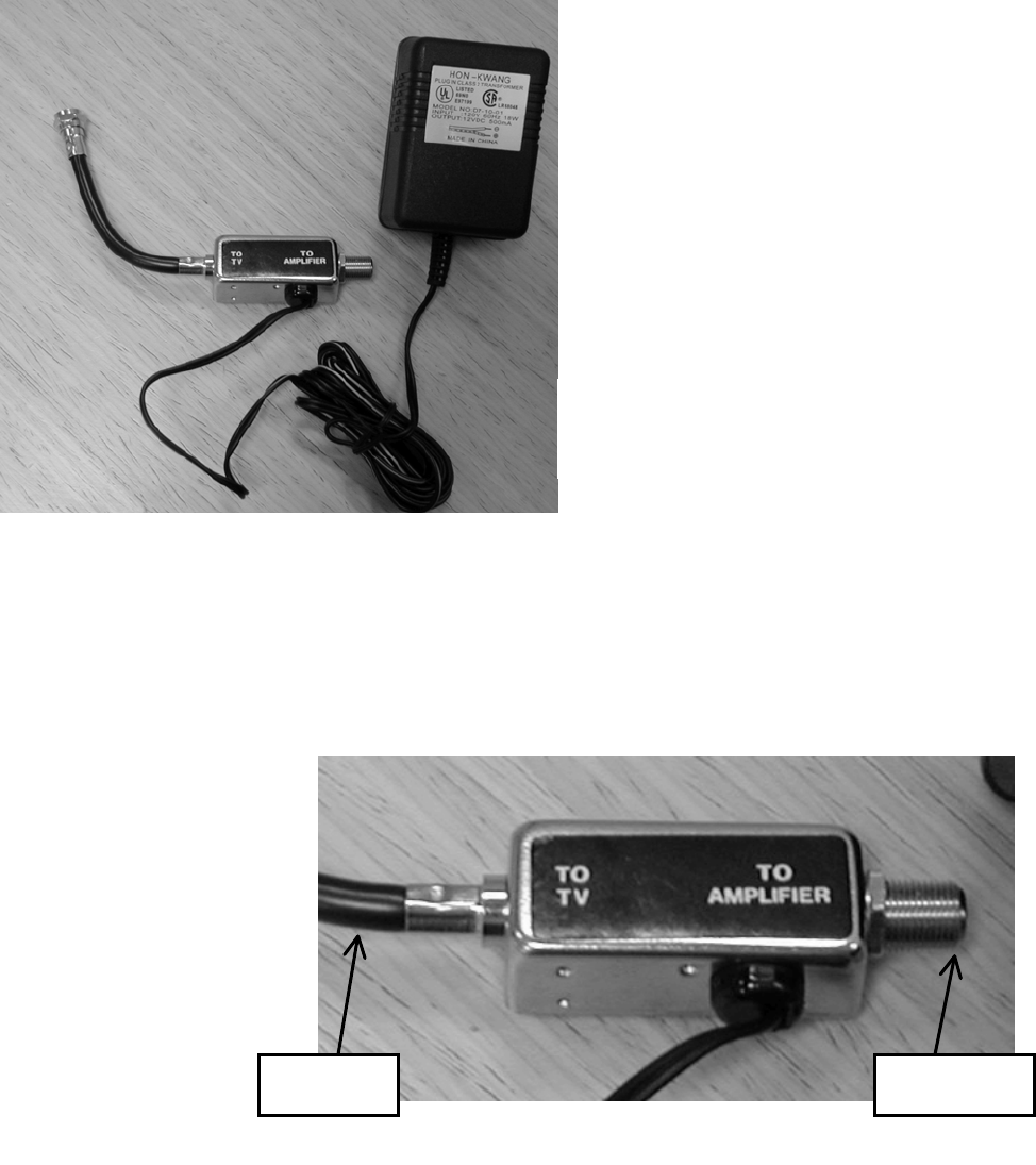
DC Power Supply and Inserter
Inside the building, route the RG-6 from the building entrance point to the modem location.
Attach an F connector and connect it to the “TO AMPLIFIER” or “TO ANTENNA” F female
connector on the power inserter. Depending on the version, the wall mounted DC power supply
may:
- be permanently connected to the
inserter as shown in Figure F4, left, or
- connect to the inserter with a small DC plug
and jack, or
- be an F connector lead to the “12 VDC IN”
connector on the power inserter. [In the F-
connector case, ARCi will supply a 12-inch F-
male-to-F-male cable to connect to the power
supply. The installer may choose to furnish a
longer cable based on the installation
specifics].
Modem (WMU)
Place the modem where it will be used and attach the short cable on the power inserter (labeled
“TO TV” or “TO MODEM” – see Figure F6) to the F connector on the rear of the modem. Connect
(the separate) modem wall mounted power supply (included with the modem) to the power
connector on the rear of the
modem. Plug both wall
mounted power supplies
into suitable AC power
sources – preferably a UPS
or surge protected power
strip. Connect a straight-
through 10BaseT LAN cable
between the RJ-45 jack on
the modem and the user
hub, router or personal
computer.
Figure F4
Power Inserter and
DC Power Supply
Figure F5
Power Inserter Detail
T
o Modem
T
o Antenna
March 1, 2002 Page F6
Note for Close-in Installations
The Subscriber Installation Schematic Diagram (Page F2) shows a 10 or 20 dB pad (attenuator)
installed between the power inserter and the modem. Small pads of many values are available
with F connectors to screw in line with the coaxial cable connection, and they may be cascaded to
sum their attenuation. At the time of system set-up it may be determined that such pads are
required in installations less than a mile from the base station site to reduce excess signal.

March 1, 2002 Page G1
G. Link Budget
Parameters

March 1, 2002 Page G2
ARCi Link Budget Parameters
Upstream minimum typical maximum
Vyyo WMU output spec (dBmV) +8 +58
IFL coax loss - Belden 9116 (calculate; length limited by downstream) 1.42 dB/100 ft @ 55 MHz
ARCi CPE IF input (dBmV) +18 +58
ARCi CPE RF output (dBm) -27 +13
ARCi CPE Tx antenna gain (dBi) 11
Path (calculate)
ARCi Hub Rx antenna gain (dBi) 16
ARCi Hub RF input level (dBm) -95 -85
ARCi Hub RF output level (dBm) -48 -38 47 dB gain
ARCi Hub RF output level (dBmV) 0 +10
IFL coax loss – Belden 1189A (calculate; length limited by downstream) 1.42 dB/100 ft @ 55 MHz
Vyyo WMTS input spec (dBmV) -15 +10 +35
Downstream
Vyyo WMTS output spec (dBmV) +20 +40
Cadco upconverter input (dBmV) +38 +45
Cadco upconverter output (dBmV) +50 +60 +65
IFL coax loss – Belden 1189A (calculate; 15 dB max loss) 4.57 dB/100 ft @ 550 MHz
ARCi Hub IF input (dBmV) +50
ARCi Hub RF output (dBm) +16
ARCi Hub Tx antenna gain (dBi) 13 EIRP = +30 dBm
Path (calculate)
ARCi CPE Rx antenna gain (dBi) 22
ARCi CPE RF input level (dBm) -92 -52
ARCi CPE IF output level (dBm) -52 -12 40 dB gain
ARCi CPE IF output level (dBmV) -4 +36
IFL Coax Loss - Belden 9116 (calculate; 15 dB max loss) 4.57 dB/100 ft @ 550 MHz
Vyyo WMU input spec (dBmV) (QPSK) -20 +35

Readers of this Manual are Encouraged
To Forward Their Corrections and Comments
To:
Rick Melzig
Advanced Radio Cells Inc.
910 Campisi Way, #1F
Campbell, CA 95008
408-558-2763 (direct)
408-371-6934 (fax)
rmelzig@arcells.com
Revision: March 1, 2002
H. Reader Feedback