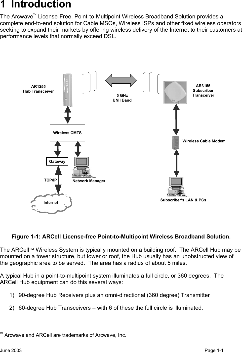
Arcwave ARC12550 Point To Multipoint Wireless System User Manual ARCi Internet
Arcwave, Inc. Point To Multipoint Wireless System ARCi Internet
UserManual.wiki
>
Arcwave
>
ARC12550 User Manual
>
User Manual 1 of 2
Contents
1.
User Manual 1 of 2
2.
User Manual 2 of 2
User Manual 1 of 2
Navigation menu
Upload a User Manual
Namespaces
Wiki Guide
HTML
PDF
Info
Views
User Manual
Discussion / Help
Navigation
![• USB: ON = connected [some modems have both USB & LAN connectors] • Activity: blinking = data (transmit or receive) The browser interface is available on some modems and contains more information. To reach it, follow these steps: • Connect a PC to either the modem’s USB or the Ethernet interface • Launch the PC’s browser, such as Microsoft’s Internet Explorer • Address: http://192.168.100.1 • User: (leave this blank) • Password: cable The screen looks like Figure 2-7. Figure 2-7: Screen for cable modem status. June 2003 Page 2-10](https://usermanual.wiki/Arcwave/ARC12550.User-Manual-1-of-2/User-Guide-386275-Page-22.png)
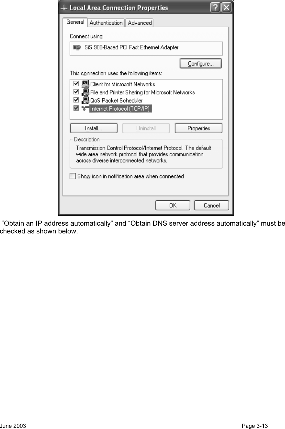
![If you are using Windows 95/98 you may need to reset the computer after making any network changes. If you are using Windows 2000/XP, you can check to see if the system obtained an IP address by opening a DOS prompt and typing ”ipconfig /all” [NOTE: the space after “ipconfig” is necessary]. The system should have IP address in the range specified by the DHCP server, something in the range of 10.10.10.x for this example. If the operating system is not able to pull a proper IP address, unplug the network cable from the computer system for 30 seconds, and the plug it back in. Wait about 30 seconds to a minute and check again to see if the system pulls an IP Address. Once the computer is set for automatic DHCP, automatic DNS, and gets an IP address from the NMS Server, open a web browser and attempt to connect to a web page. If the web page loads, then your active DHCP server in the NMS Server machine is configured properly. Any computer behind a wireless modem and on the local network should be able to go out to the Internet if it is set to obtain IP addressing information through a DHCP server. *Note: This portion of document that outlines how to check for DHCP setting was written for the Windows XP operating systems. Getting to the “Local Area Connection Properties” will vary slightly depending on which version of Windows you are using 3.6 Wireless Network System Testing After installing the Hub equipment, take a subscriber unit into each of the Hub sectors and verify that Internet service is available and that it has the planned range. June 2003 Page 3-14](https://usermanual.wiki/Arcwave/ARC12550.User-Manual-1-of-2/User-Guide-386275-Page-36.png)