Arcwave ARC12550 Point To Multipoint Wireless System User Manual ARCi Internet
Arcwave, Inc. Point To Multipoint Wireless System ARCi Internet
UserManual.wiki
>
Arcwave
>
ARC12550 User Manual
>
User Manual 2 of 2
Contents
1.
User Manual 1 of 2
2.
User Manual 2 of 2
User Manual 2 of 2
Navigation menu
Upload a User Manual
Namespaces
Wiki Guide
HTML
PDF
Info
Views
User Manual
Discussion / Help
Navigation
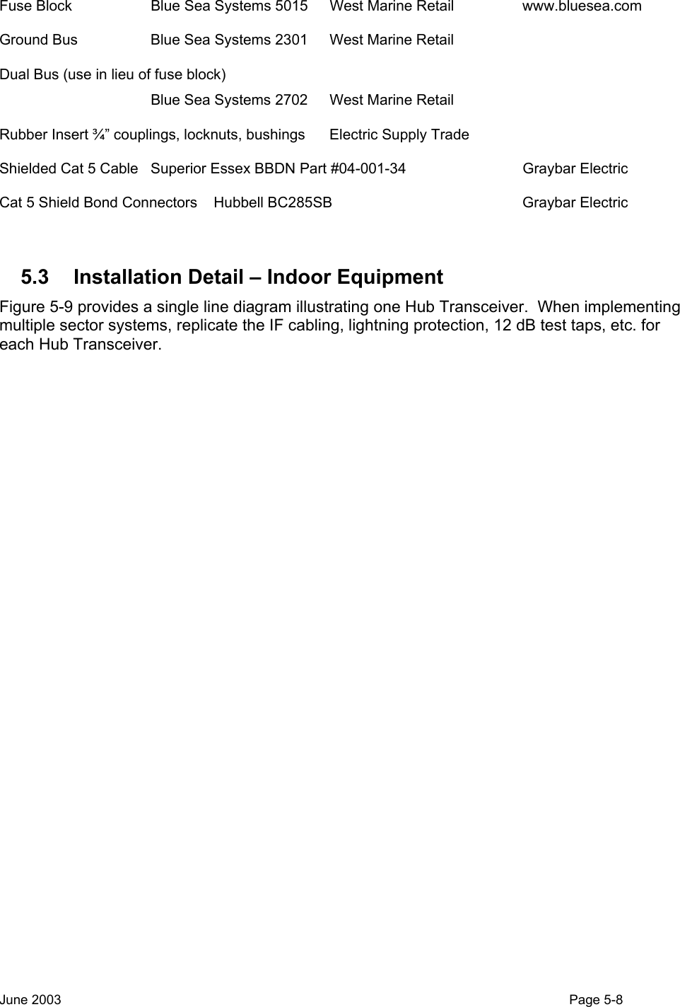
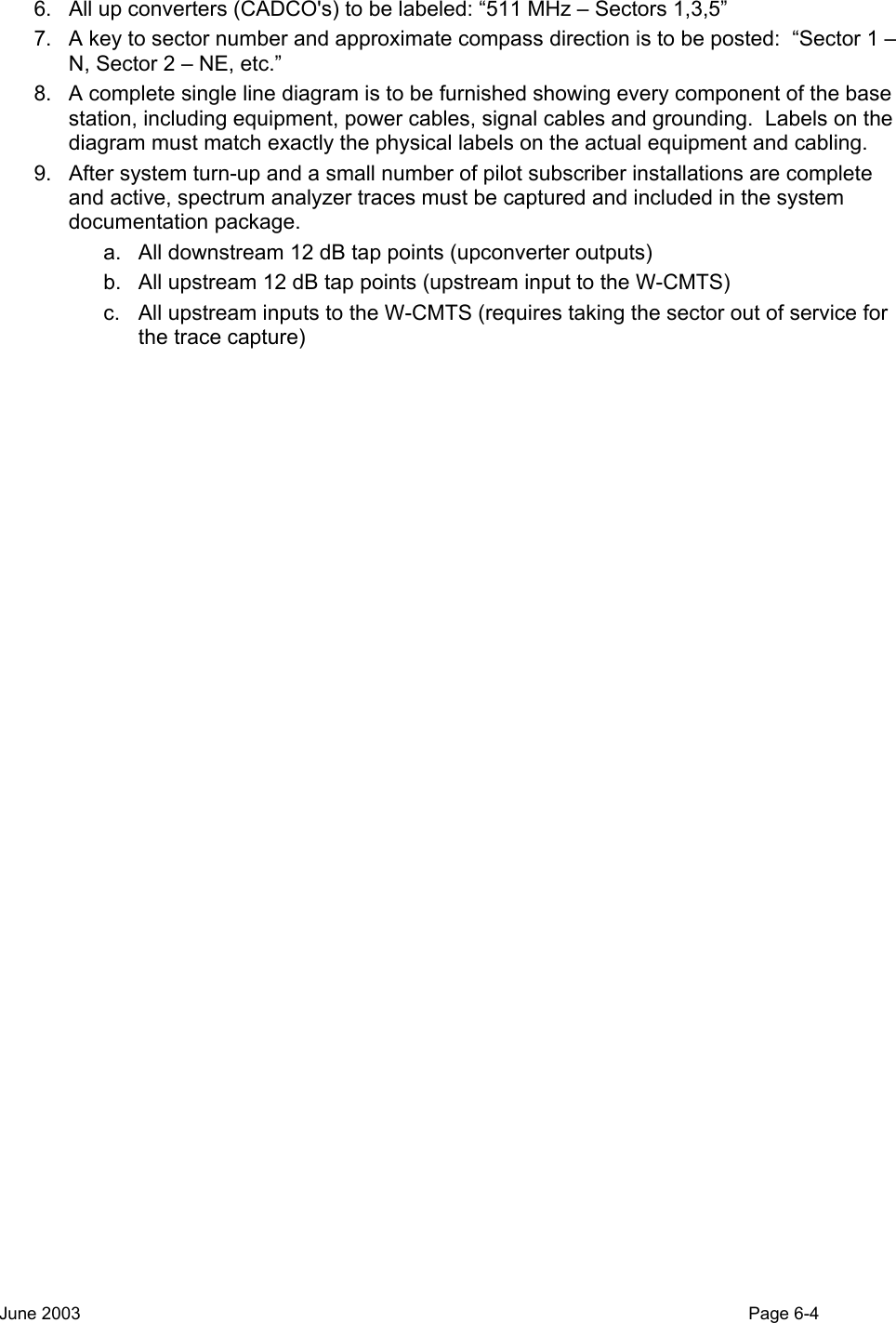
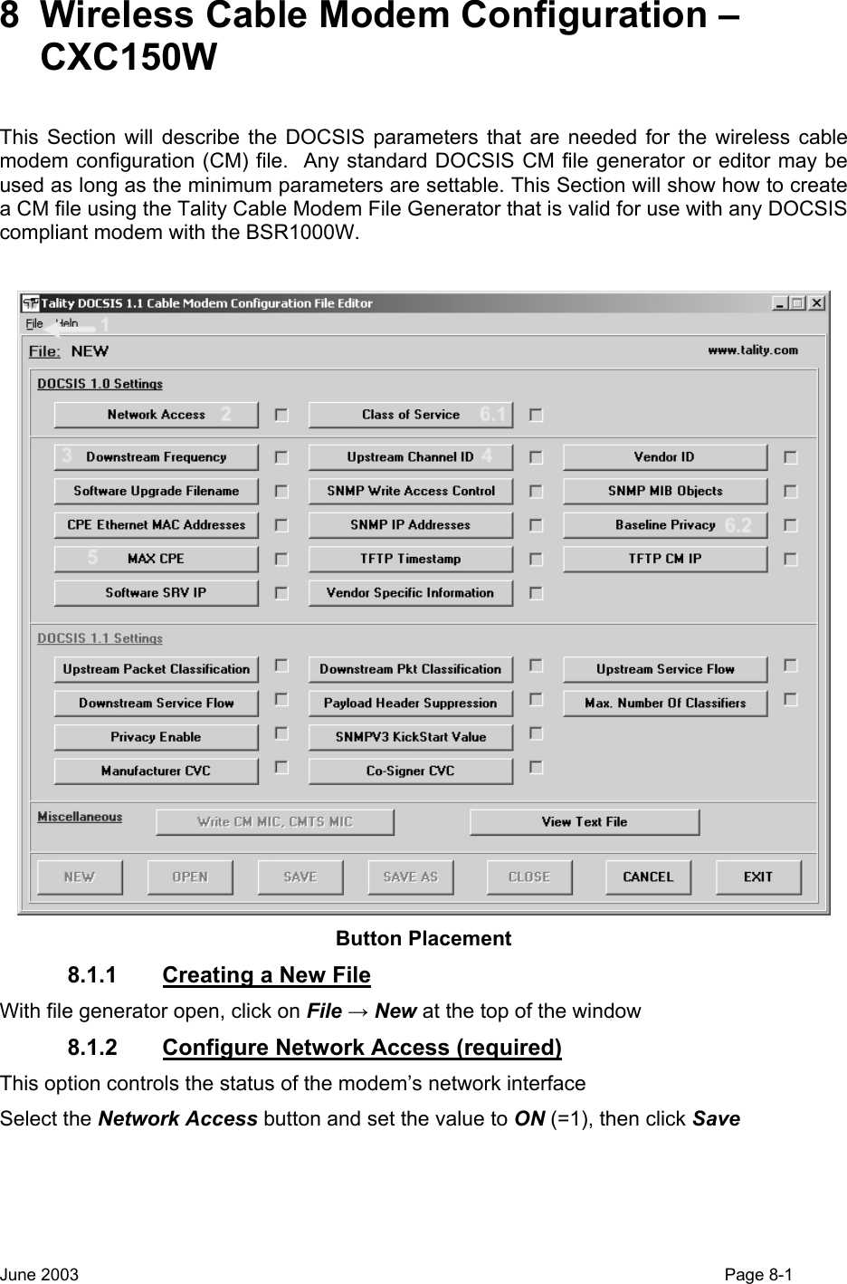
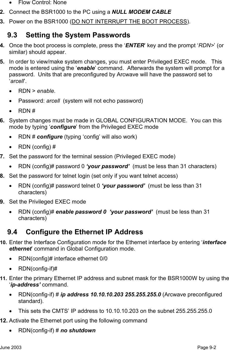
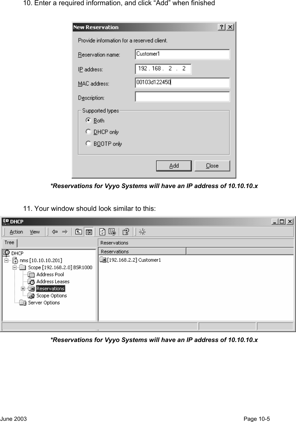
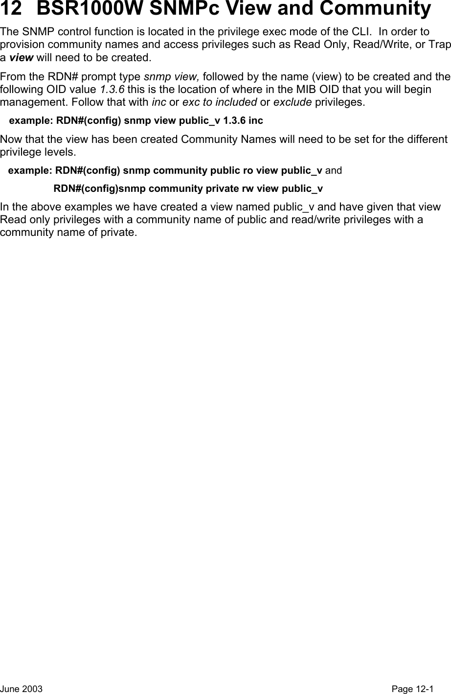
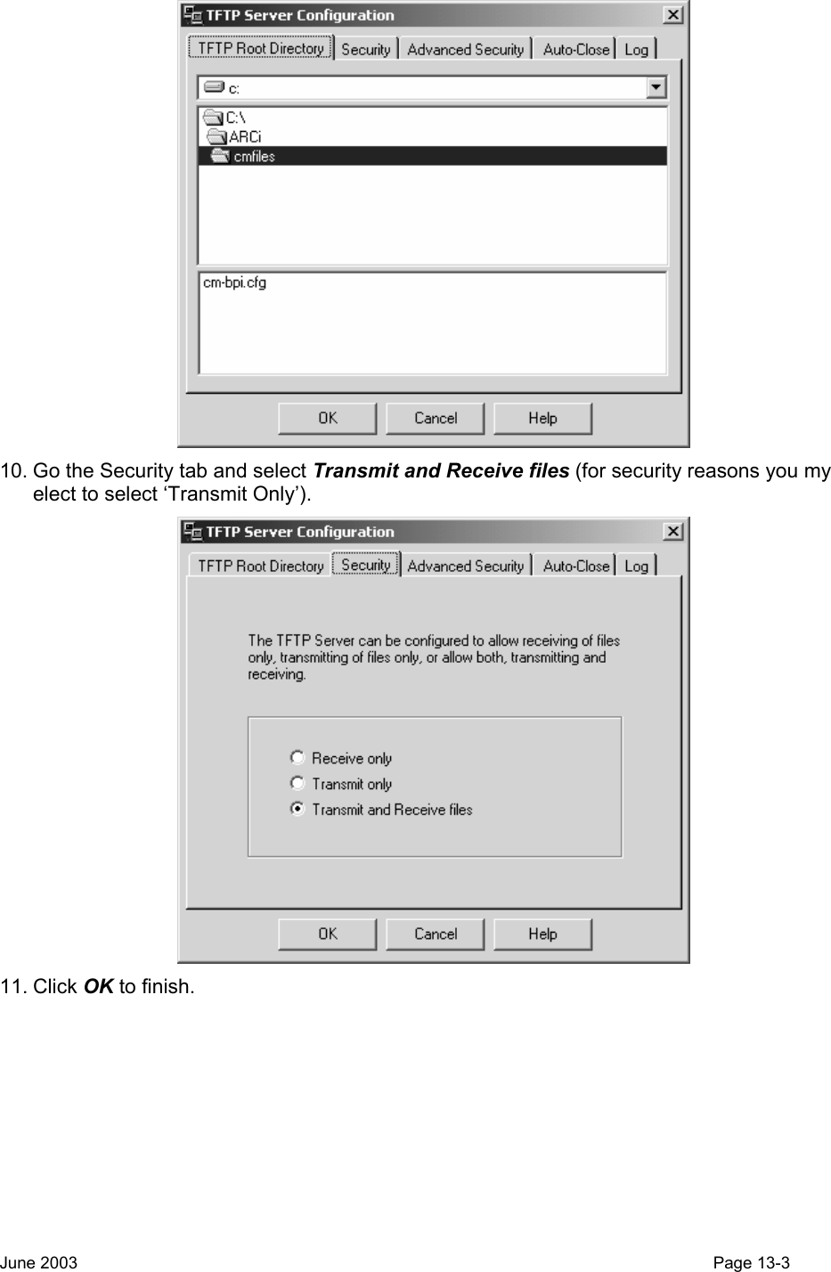
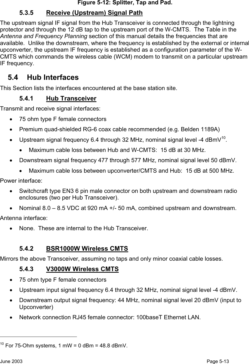
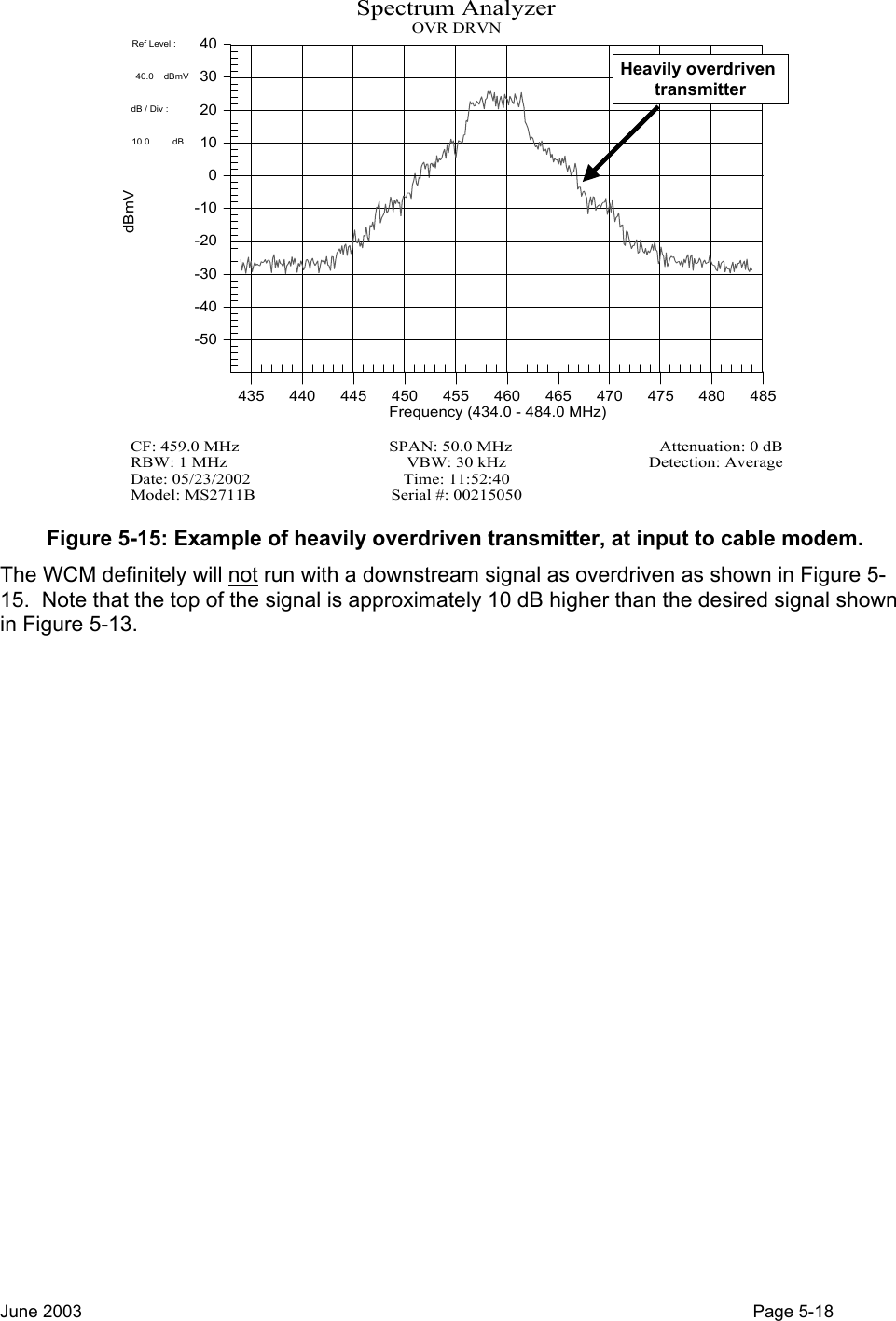
![ARCell IF cables(3 downstream + 6 Upstream)Lightning protectors for ARCell IF cables Figure 5-11: Details of Fig 5-10 IF cable protection. 5.3.2 DC Power The Hub Transceiver requires 8.0 – 8.5 Vdc at the transceiver modules and draws approximately 900 mA of current. In a one or two sector installation a small variable voltage linear DC power supply capable of supplying at least 1000 mA is employed. Arcwave has successfully tested the following power supply in a one or two sector configuration: Agilent model E3610A The voltage (IR) drop of the power cable is calculated and the output of the DC supply is set appropriately. In a multi-sector installation the DC power supply is chosen with sufficient capacity to deliver at least 1000 mA for each Hub Transceiver. The DC+ lead is sized to provide reasonable voltage drop between the DC supply and the Outdoor Junction Box (OJB) installed near the Hub Transceivers. [It is the installer’s responsibility to furnish, assemble and install the OJB]. The DC power supply is then adjusted to provide 8.0 – 8.5 Vdc at the Transceiver connector. A power supply with an ammeter is a great help when trouble-shooting a Hub since experience has shown that a bad transmitter or receiver module may be “dead” or it may be drawing half its normal current. In either case it is usually very noticeable. 5.3.3 Transmit (Downstream) Signal Path In the BSR1000W the Downstream upconverter is internal, and the output level can be set via the command line interface or network management software. In the V3000W, the downstream signal is connected to the external upconverter (normally mounted in the rack with the W-CMTS). A 10 dB pad is inserted at the input to the upconverter to set the proper level. June 2003 Page 5-11](https://usermanual.wiki/Arcwave/ARC12550.User-Manual-2-of-2/User-Guide-386316-Page-5.png)
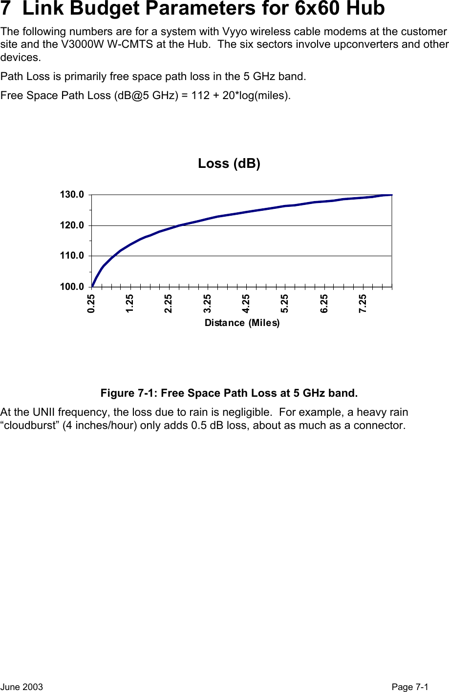
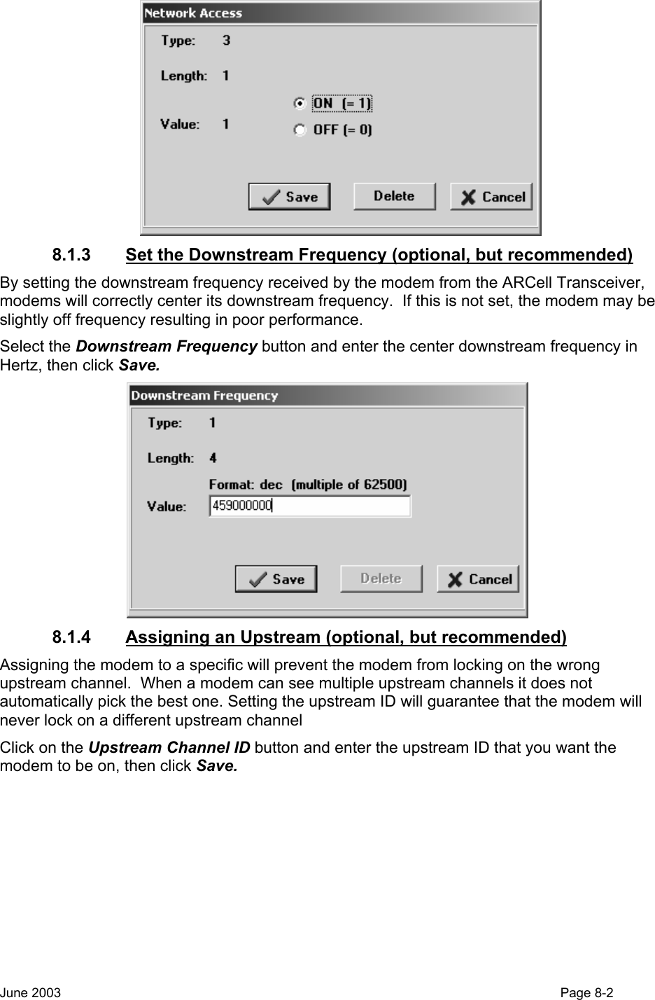
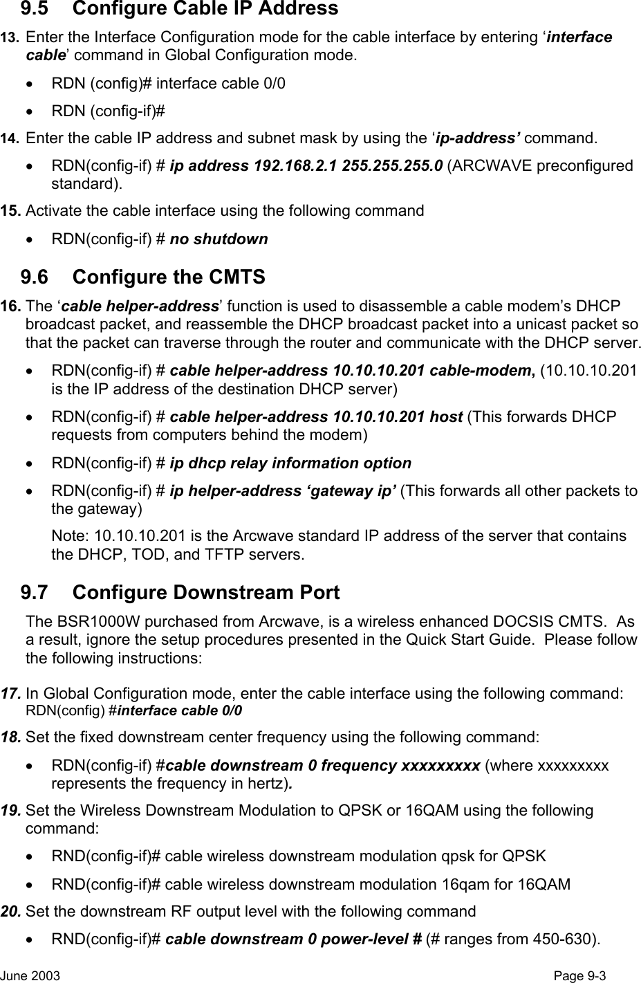
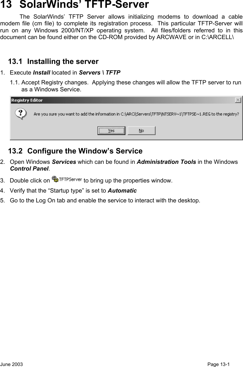
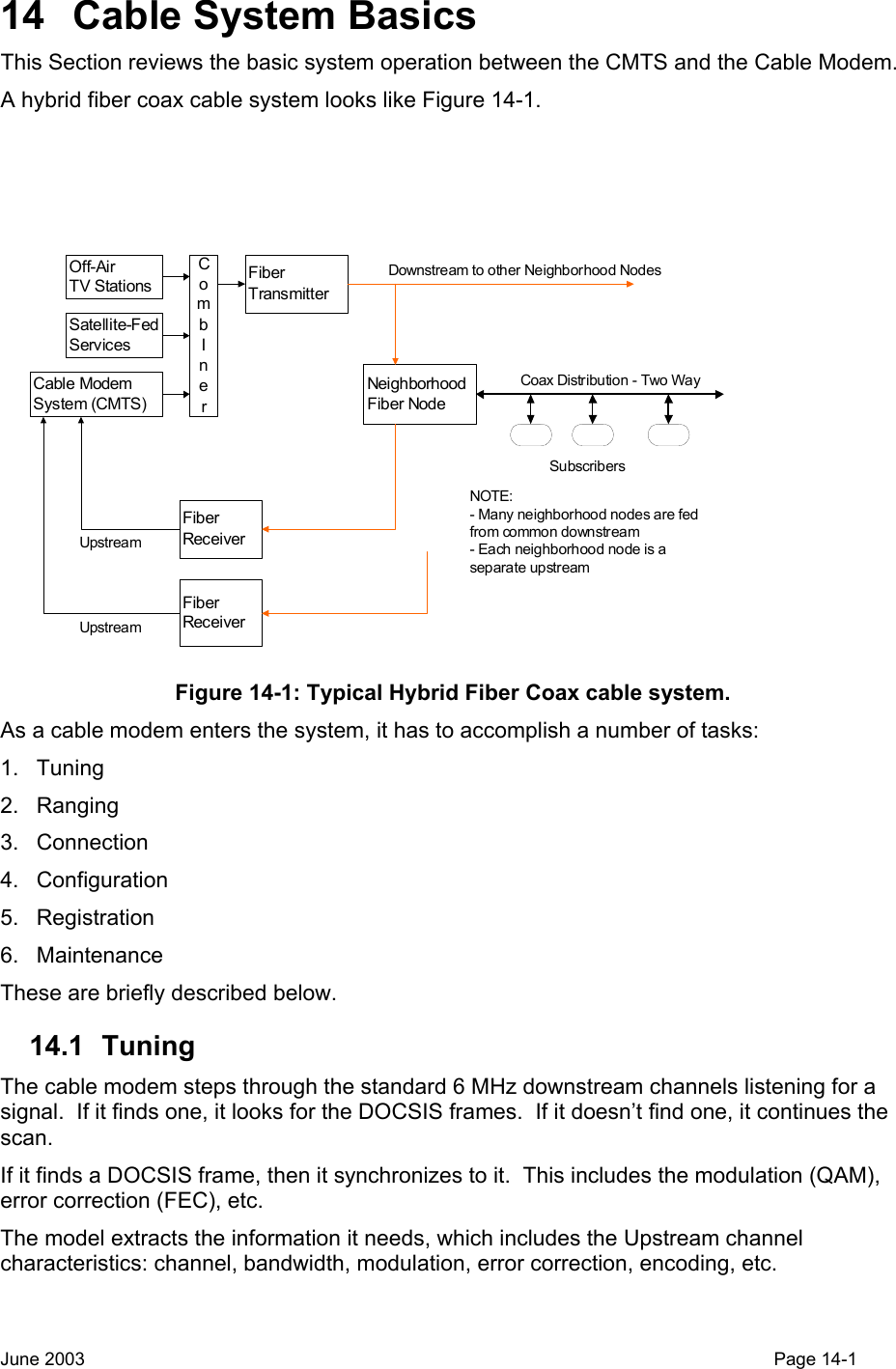
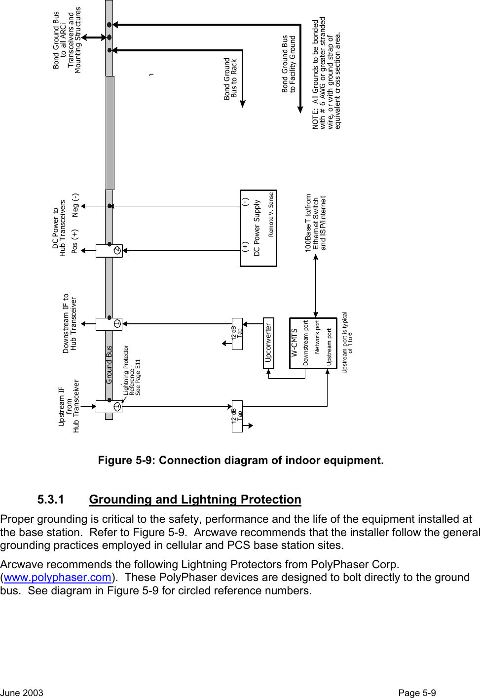
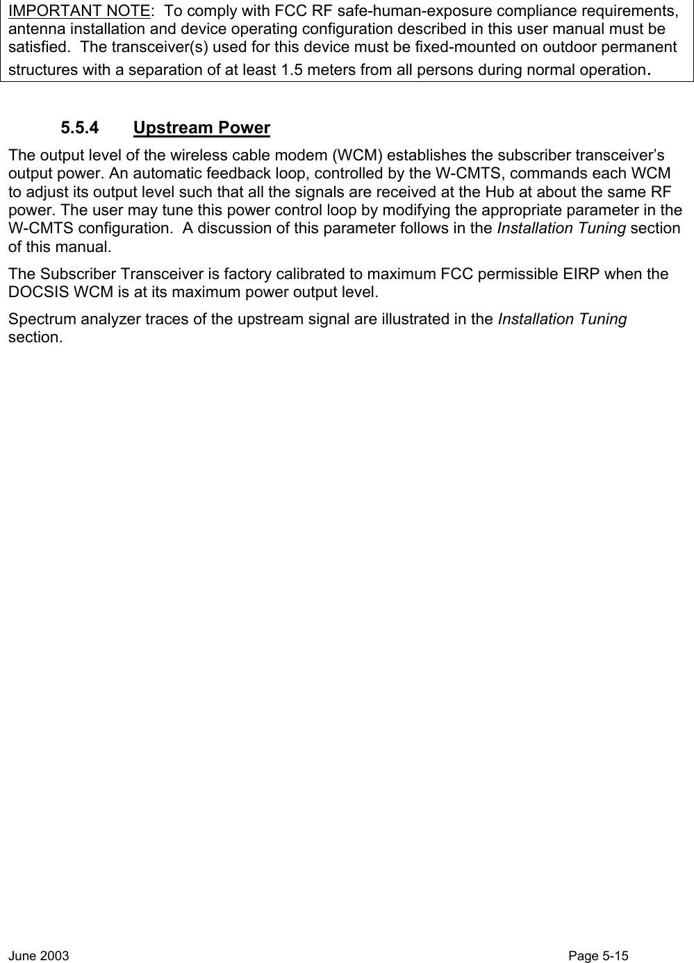
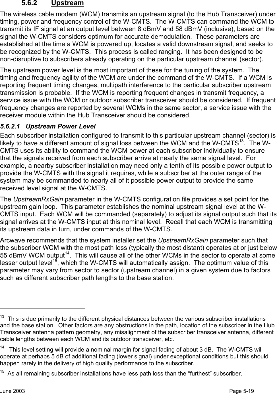
![• The Ethernet switch port to which the V3000W W-CMTS is connected must be optioned to 100 Mbps, Full Duplex, No Auto-Negotiate. 5.4.3.1 Upconverter (Internal or external) • 75 ohm type F female connectors • Input signal frequency 44 MHz; level range +38 dBmV to +45 dBmV. • Output signal frequency 477 through 577 MHz; maximum signal level +60 dBmV. 5.5 System Level-Setting Notes 5.5.1 General The ARCell base station and subscriber transmitters are designed for linear operation at the maximum output power allowed for compliant operation under the FCC part 15 regulations. In both the headend and the subscriber units the input power level to the ARCell transceivers determines the output power. There is no gain adjustment available to the user in the transceiver. 5.5.2 Downstream Power The AR3155 Hub Transceiver is factory calibrated to provide RF power output of +36 dBm maximum EIRP (FCC Rules Section 15.247) when the input power applied to the upconverter IF input connector is +35 dBmV. This is the level required for FCC compliance. 5.5.3 Downstream Power Adjustment Procedure 1. Disconnect the downstream IF cable at the input to the Hub Transceiver and connect the cable to the input of a suitably calibrated RF power meter such as a CATV level meter. Ensure that the IF signal power does not exceed +35 dBmV. 2. Alternatively, a spectrum analyzer can be utilized if it has a 75 ohm input impedance and can display power in dBmV. a. Adjustment must be made for the resolution bandwidth (RBW) of the analyzer11. For example, in the case of the AR3155, if the RBW is set for 1 MHz, the actual power level will be 10log(5.25) or 7.2 dB higher than the average power displayed on the analyzer. 3. Set the IF output level of the W-CMTS or external upconverter, or by inserting fixed attenuators as needed. 4. If the AR3155 Hub Transceiver is inaccessible for power measurement, the level at the W-CMTS or external upconverter can be measured and adjustment made for transmission line loss12. For example, if the transmission line loss is known to be 10 dB including any taps or splitters, the W-CMTS or external upconverter output can be set for +45 dBmV which will provide the required +35 dBmV power level at the input of the Hub Transceiver. In any case, it is the responsibility of the system operator to ensure that the proper input level is applied to the AR3155 Hub Transceiver. 11 The formula is (actual power) = (displayed power) + 10log[(signal bandwidth) ÷ (RBW)]. 12 See cable manufacturer’s specifications. Standard RG-6 coaxial cable has a loss of 4.6 dB /100 ft. at 500 MHz. June 2003 Page 5-14](https://usermanual.wiki/Arcwave/ARC12550.User-Manual-2-of-2/User-Guide-386316-Page-8.png)
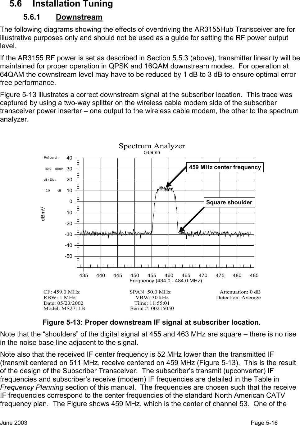
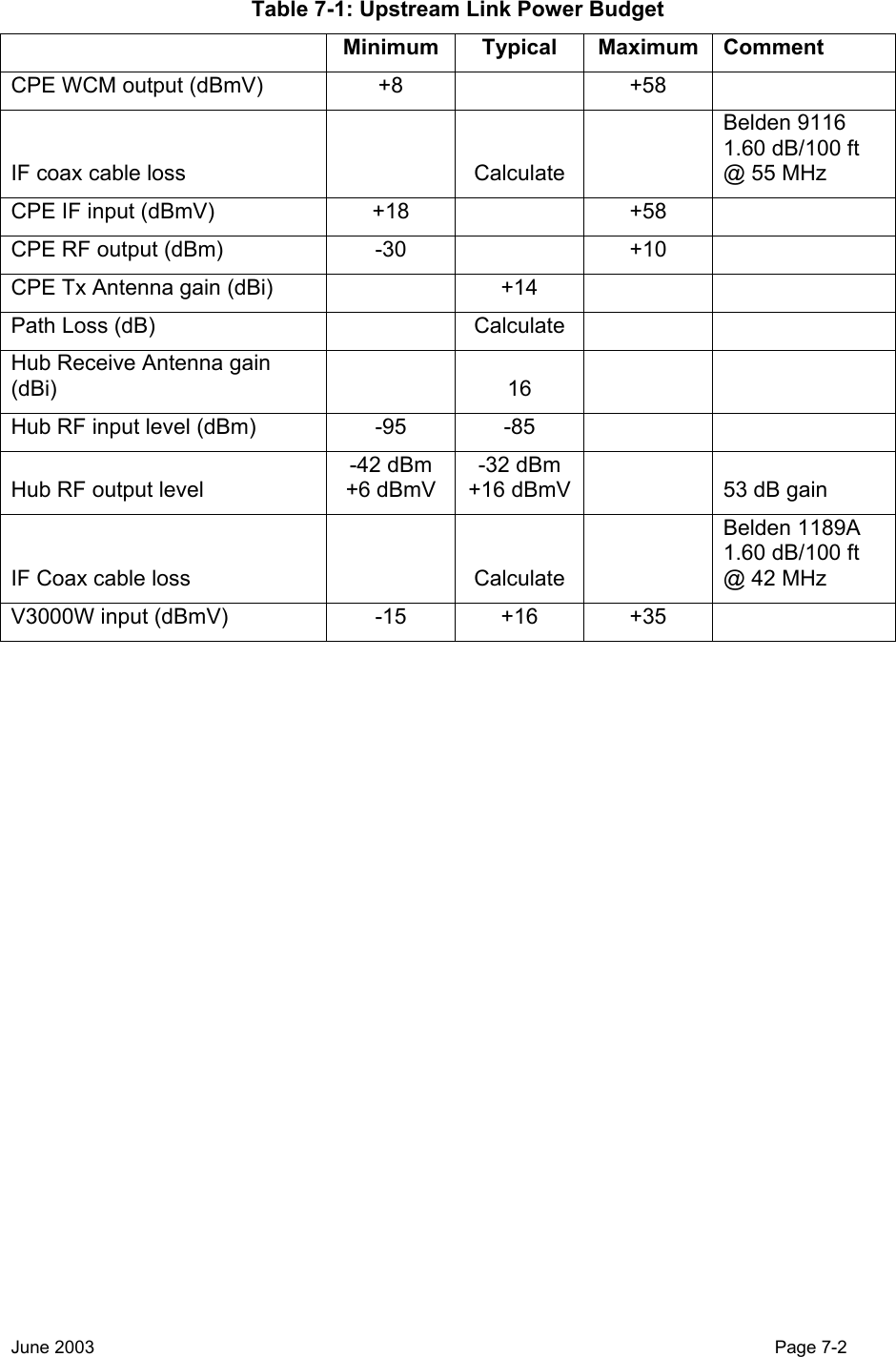
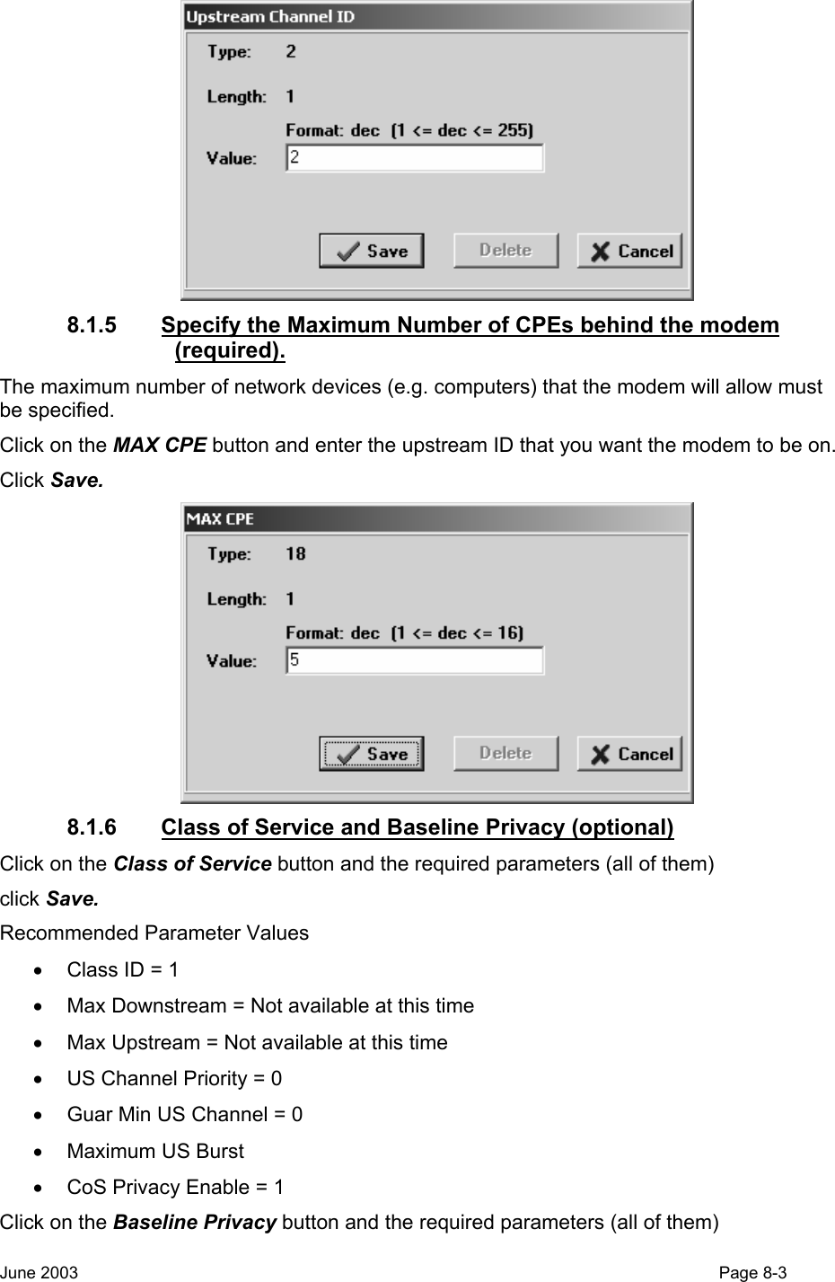
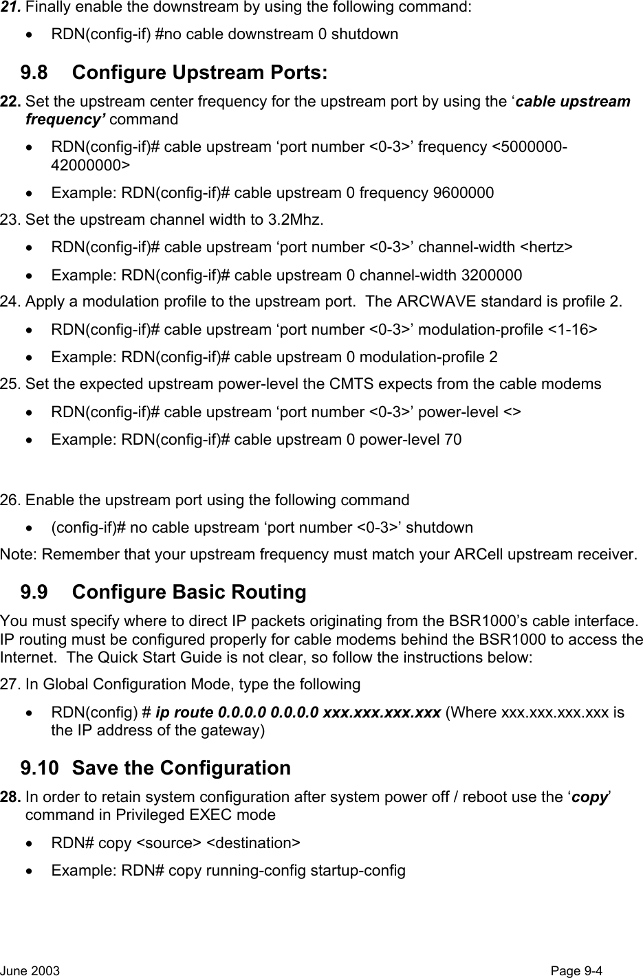
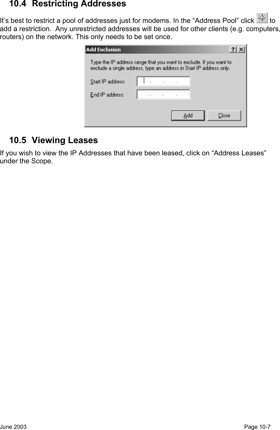
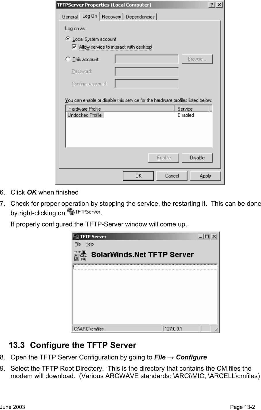
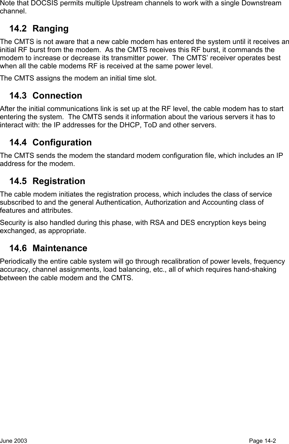
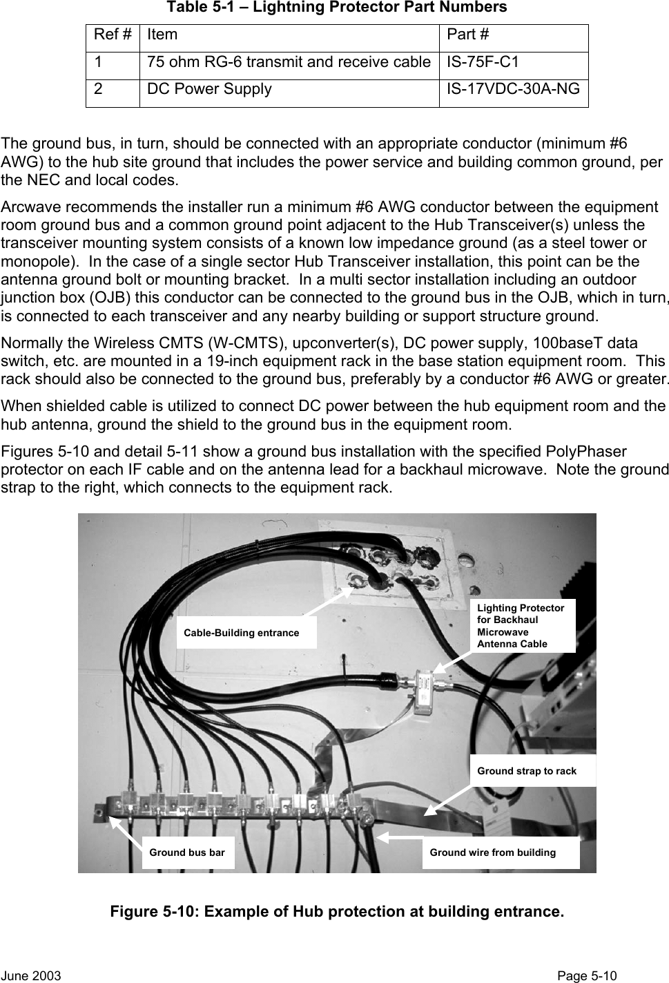
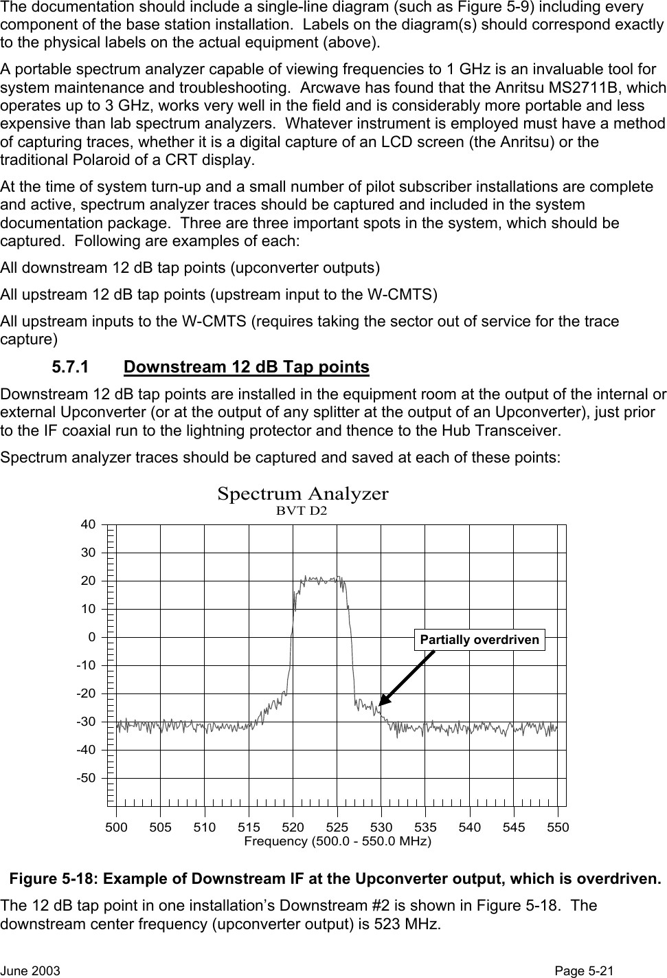
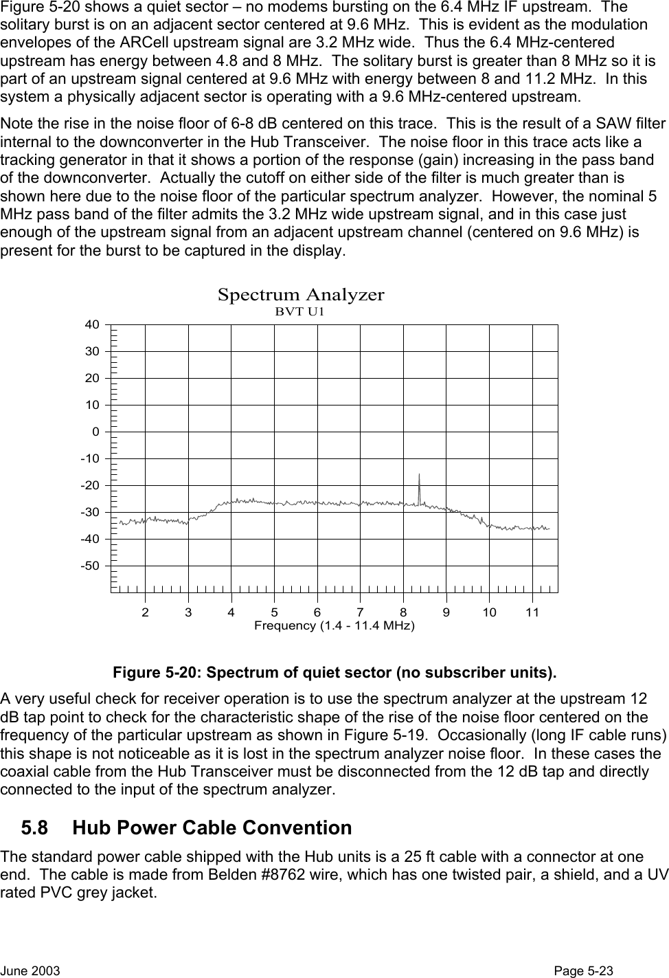
![The trace was in Figure 5-17 captured at the 12 dB tap on the upstream input to the W-CMTS. It is centered on upstream frequency 6.4 MHz and built up with Max Hold for 30 seconds. Note that the bursts from the various WCMs are arriving at nearly the same amplitude. [Disregard signal below 4 MHz as noise, etc.]. -80-70-60-50-40-30-20-100102345678910 11Ref Level : 10.0 dBmV dB / Div : 10.0 dB M1Spectrum Analyzer30 SECSModel: MS2711B Serial #: 00215050Date: 05/23/2002 Time: 11:10:30RBW: 1 MHz VBW: 30 kHz Detection: AverageCF: 6.4 MHz SPAN: 10.0 MHz Attenuation: 0 dBdBmVFrequency (1.4 - 11.4 MHz)M1: -42.55 dBmV @ 11.4 MHz Figure 5-17: Spectrum at Upstream input to W-CMTS. See also Figure 5-19, which was taken at the same point at another installation. There is an important subtlety here. The individual modem bursts are not spikes as this display might suggest. Rather, each is a “standard” QPSK modulation envelope, 3.2 MHz wide, centered at 6.4 MHz. They appear as spikes as the bursts are very short duration relative to the sweep of the spectrum analyzer “window”. Thus only portions of the modulation envelope are captured in the display. 5.7 Installation Labeling and Documentation It is strongly recommended that the installer thoroughly document the system after turn-up and a small number of pilot subscriber installations are complete and active – preferably at least one in each sector. A copy of this documentation should be kept in a binder at the base station for maintenance personnel access and hand updates as changes are made. Examples of mandatory labels: • Base station cabling: should be labeled at both ends as to its application: e.g. “Sector 3 U/S”, or “DC to Sector 1”. Many antenna installers utilize bands of colored tape to identify cabling running from the equipment room to the antennas. If so installed, a ‘key’ to the coding should be posted: “red-red-yellow = Sector 1 D/S” • 12 dB tap points: “Sector 3 D/S” • Upconverters (CADCO): “511 MHz – Sectors 1,3,5” • Sector number approximate compass direction: “Sector 1 – North, Sector 2 – NE, etc.” June 2003 Page 5-20](https://usermanual.wiki/Arcwave/ARC12550.User-Manual-2-of-2/User-Guide-386316-Page-14.png)

![3. Ground the Negative side of the Hub Transceiver DC cable to the OJB common ground bus. 4. Ground the shields of all DC and IF cables to the OJB common ground bus. 5. If there is any doubt about the continuity of structural ground between the OJB grounding point and the equipment room electrode, run a properly terminated (minimum) #6 copper cable from the OJB common ground bus to the ground bus bar in the equipment room. 6. Route the IF, DC power cable and ground cable from the OJB to the base station equipment room. Utilize appropriate mounting hardware and/or UV-rated tie-wraps. 6.3 Other Suppliers’ Outdoor Equipment 1. Backhaul microwave antennas, etc. are to be mounted on the supporting structure per the recommendations of the manufacturer. All requirements for attachment, grounding, connector weatherproofing, etc. are to be carefully observed. 2. Route all cables and/or waveguide from the outdoor equipment(s) to the base station equipment room. Utilize appropriate mounting hardware and/or UV-rated tie-wraps. 6.4 Equipment Room Installation – Cable Entrance and Grounding 1. Mount a ground bus bar adjacent to the cable entrance to the equipment room structure. a. Connect the ground bus bar to the ground electrode with a properly terminated (minimum) #6 copper cable [or copper ground strap of equivalent cross-sectional area] as described in the National Electric Code sections 820-33, 820-40 and 820-41. A common technique is to route the (minimum) #6 copper cable to a driven ground rod adjacent to the point of entry of the coax cable to the building containing the equipment room, and thence to the building electrical service ground point per NEC 820-40. It the Hub Transceivers are mounded on a metallic tower structure adjacent to the equipment room a similar properly terminated (minimum) #6 copper cable should also be run from the electrode to the tower steel. All grounding to conform to local codes. b. Connect the ground bus bar to the indoor equipment rack with appropriate copper strap or (minimum) #6 copper cable. c. Note that ground wires employed for lightning protection must NEVER be routed in metallic conduit, pipe, EMT, etc. If lightning ground wires are enclosed they must be routed through non-metallic tubing such as PVC. 2. Mount a suitable lightning protector (e.g. PolyPhaser Model IS-75F-C1) to the ground bus bar for each IF coaxial cable between an Hub Transceiver and the equipment room. 3. Mount a suitable lightning protector (e.g. PolyPhaser Model IS-17VDC-30A-NG) to the ground buss bar to protect the DC power supply. 4. Mount a suitable lightning protector to the ground bus to protect any other cable and/or waveguide routed between the antenna mounting structure and the equipment room. 5. Connect all shields associated with any wiring entering or leaving the equipment room to the ground bus bar. 6. Ensure that all coax cables and DC power cables are properly terminated and connected to the “antenna” or “surge” side of each lightning protector. 7. Note that the “equipment” or “protected” side of each lightning protector is a convenient and appropriate point to demarcate the outside portion of the installation as specified above, and the inside installation which will be specified following. June 2003 Page 6-2](https://usermanual.wiki/Arcwave/ARC12550.User-Manual-2-of-2/User-Guide-386316-Page-21.png)
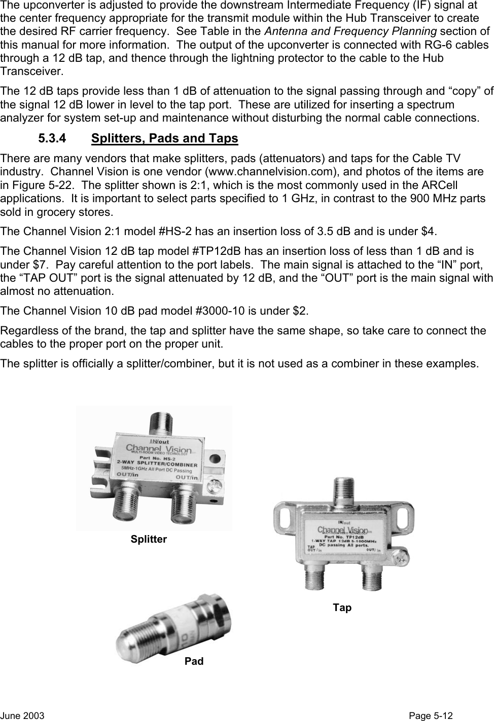
![6.5 Equipment Room Installation – Inside Equipment 1. Customer to furnish cabinet or open-frame 19” equipment rack. a. Cabinet racks to be secured to floor per local earthquake standards. Open frame racks must be secured and braced at the top as required by local codes and practice. b. Minimum recommended clearances for equipment access and operation: 24” in the rear and 36” in the front for cabinet racks, proportionally greater for open frame racks. c. Bond at least one side of front rack rail to the inside ground bus bar (item C1, above) with properly terminated (minimum) #6 copper cable [or copper ground strap of equivalent cross-sectional area]. 2. All electronic equipment: Wireless CMTS (W-CMTS), PC(s), upconverters, power supplies, Ethernet switches, routers, UPS, etc. to be secured to the rack by at least four standard 10-32 rack screws. 3. If vertical rack space permits, it is desirable to leave one rack unit (RU = 1 ¾”) between each rack-mounted device. At minimum, one space should be left above heat generating devices such as rack mount PCs. 4. Support all large heavy devices (PCs, UPS) with manufacturer-provide rear mounting hardware, or at minimum, a 1 RU blank rack panel secured across the rear rack rails in the space immediately below the device to be supported such that the bottom of the device rests on the top edge of the panel. 5. Furnish at least one dedicated 120 VAC 20 amp power circuit to a suitable receptacle(s) within two feet of the equipment rack. In areas of “dirty” power, protect all equipment with at least an appropriately sized shunt type power line protector. 6. Arcwave strongly recommends protecting the entire base station facility (including all outdoor equipment) with a suitable uninterruptible power supply (UPS). One unit Arcwave has found to be sized appropriately for one of its base stations is an APC 2U rack mount SmartUPS 1400 VA-RM. Ensure that the UPS is bonded to the rack or ground bus per manufacturer’s instructions. 7. In addition to the equipment power circuit specified in item E5 (above), provide additional 120 VAC outlets in the vicinity of the equipment rack for portable test equipment, laptop computer chargers, etc. 8. Furnish suitable ambient and task lighting in the vicinity of the equipment rack to permit installation and maintenance activities. 9. Provide for building security appropriate to the installation environment. 6.6 Base Station Installation Documentation 1. Complete documentation immediately after system turn-up. 2. One complete copy is to be kept in a loose-leaf binder at the base station for maintenance personnel access and hand updates. At least one-second copy is to be provided to the system operator. 3. Every wire and cable is to be labeled with a suitable permanent wire marking system. Examples of label text are: “Sector 3 U/S”, or “DC to Sector 1”. 4. Many antenna installers utilize bands of colored tape to identify cabling running from the equipment room to the antennas. If so installed, a ‘key’ to the coding must be furnished, e.g., “red-red-yellow = Sector 1 D/S” 5. All 12 dB taps and signal splitters to be labeled: “Sector 1 D/S” June 2003 Page 6-3](https://usermanual.wiki/Arcwave/ARC12550.User-Manual-2-of-2/User-Guide-386316-Page-22.png)