Arcwave AX125500 Point To Multipoint Wireless System User Manual Market Requirements
Arcwave, Inc. Point To Multipoint Wireless System Market Requirements
Arcwave >
Contents
- 1. User Manual 1 of 2
- 2. User Manual 2 of 2
User Manual 2 of 2
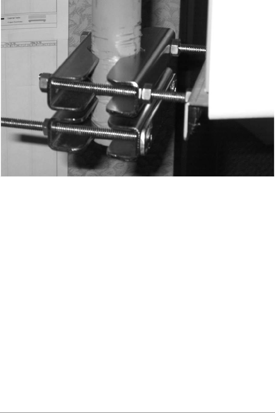
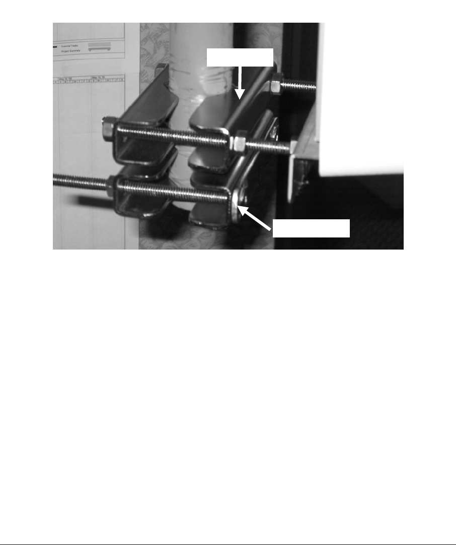
Figure 3-10: Pole Mount with temporary pivot bracket detail.
It is often convenient to temporarily mount a spare pair of brackets below where the
Access Point will be placed. This serves as a pivot point, as well as stopping
slippage during installation, as in Figure 3-10.
While downtilt is normally not needed, the nuts on either side of the Access Point’s
“ears” also serve to establish downtilt. The following Figures 3-11 & 3-12 show the
measurement, and the difference in the top and bottom measurements creates the
downtilt.
ARCXtend manual, August 2003 3-16
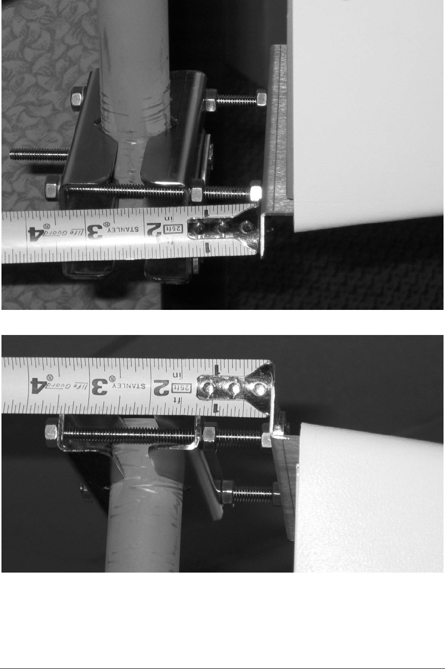
Figure 3-11: Measuring bottom spacing.
Figure 3-12: Measuring top spacing.
ARCXtend manual, August 2003 3-17
3.8.1 Bracket Mount
There is a wide range of hardware vendors and approaches to mounting a pipe on a
utility pole. For example, Valmont or RFS Celwave (Figures 3-13 & 3-14) will mount
on the common wooden utility pole and any pipe of the proper OD can be clamped
to it.
Arcwave makes a bracket with the pipe welded to the bracket, which is simpler and
lighter than the general purpose mounting kits. This was shown in the previous
photographs.
The industry has many variations on utility pole materials, e.g., metal & cement, and
there are many solutions to mounting a pipe on those poles.
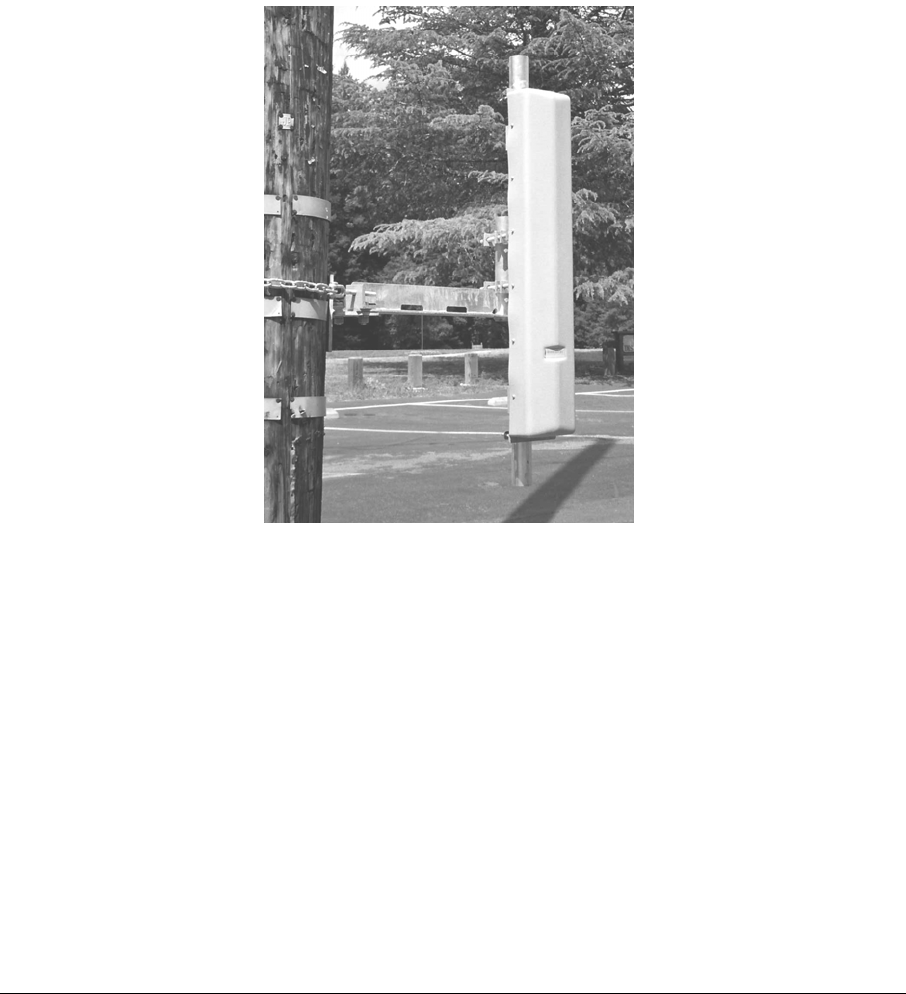
The Vertical-Mount Access Point mounts on the pipe.
Figure 3-13: Valmont Chain-Mount Pipe-Mount Kit combination.
ARCXtend manual, August 2003 3-18
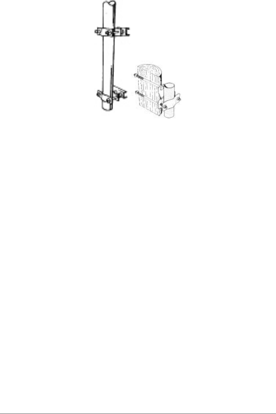
Figure 3-14: RFS Celwave Pole Brackets.
3.9 Strand Mount
The majority of Access Points are expected to be mounted on the wire strand that
supports the coaxial cable system.
The strand-mount kit is designed to support a Horizontal-Mount Access Point.
There is an arm at each end of the Horizontal Access Point. The top of the arm is
clamped to the strand, as in Figure 3-15.
The top of the arm is designed to slip in between the strand and the coaxial cable,
which is usually spiral wrapped to the strand.
ARCXtend manual, August 2003 3-19
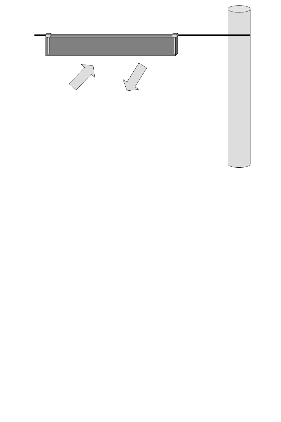
Figure 3-15: Strand-mounted Access Point.
In high-wind installations, the Access Point can be stabilized by clamping the bottom
of the arm to a second strand.
ARCXtend manual, August 2003 3-20
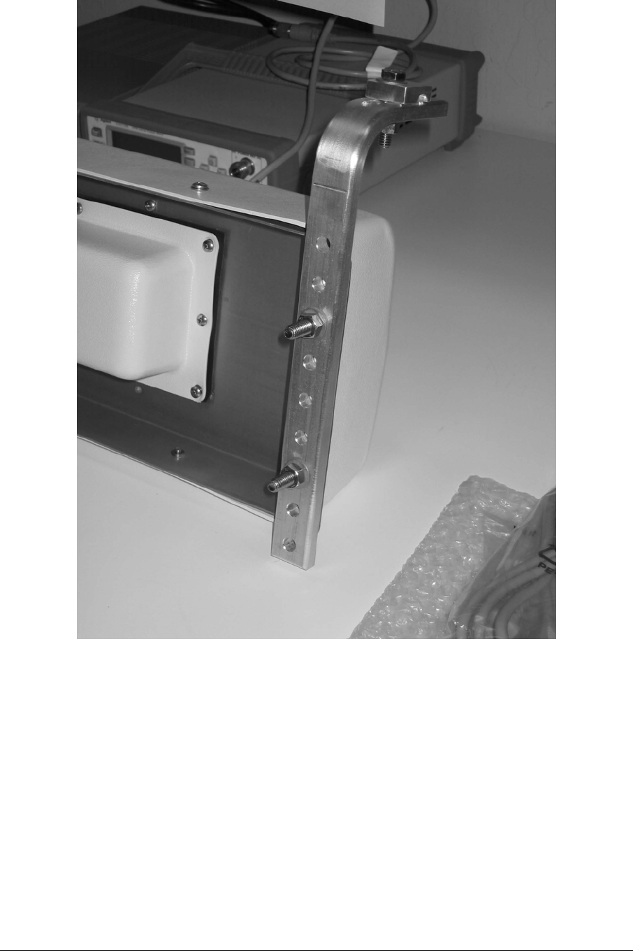
Figure 3-16: Strand Mount bracket detail.
Figure 3-16 shows the detail of the strand mount bracket.
ARCXtend manual, August 2003 3-21
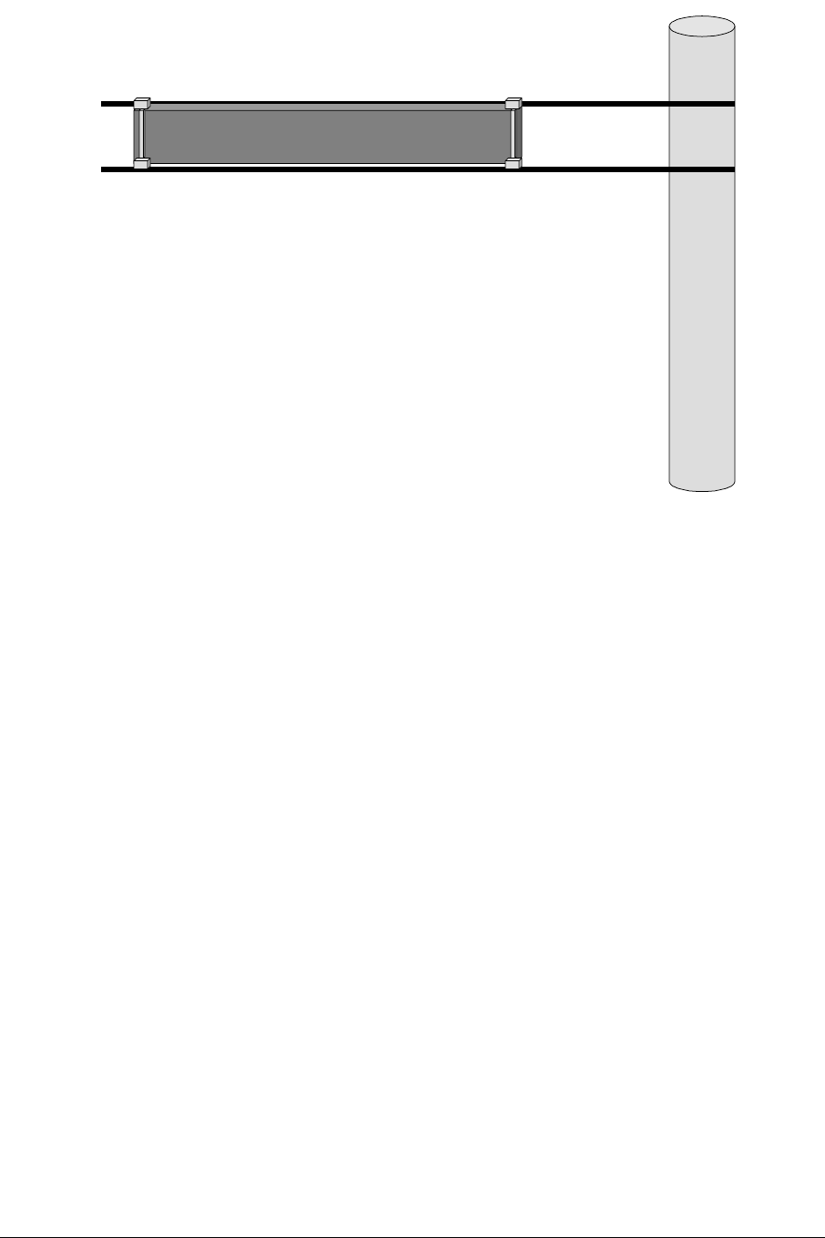
Figure 3-17: Strand-mounted Access Point with dual clamping.
3.10 Verify Service Area
When the Access Point is installed, its coverage should be verified by a sampling of
building locations.
ARCXtend manual, August 2003 3-22

4 Command Line Interface
The ARCXtend has a Command Line Interface (CLI) function.
The commands will be used by a technician in preparing an Access Point for service
and field installation.
Some technicians like to “burn-in” a unit prior to field deployment, and this burn-in
period is a practical time to also pre-configure a unit via CLI for the parameters used
in the network.
4.1 Physical Interface
The physical interface is a four-wire EIA/TIA-485, which is a buss interface.
The EIA/TIA-485 interface parameter settings are: 9600 baud, 8 bit, 1 stop bit, no
parity, no flow control, local echo OFF.
NOTE: Most PCs will require an RS-232 to EIA-485 converter.
4.2 Command Line Characteristics
All valid commands are automatically saved as soon as they are accepted.
Saved commands are not changed by power cycling (ON/OFF).
All valid commands are echoed by the Module being addressed, so a technician can
visually verify that the correct action has been taken.
Commands or parameter values that are not used by the Module are refused (no
change in settings) and echoed with the message: “Invalid Command/Parameter”, or
a similar response, and a list of the acceptable input options.
The “invalid” message is followed by the login response.
Commands and parameters are NOT case sensitive.
Commands have no spaces.
Characters are 8-bit ASCII visible characters. Backspace is the only permitted
invisible ASCII character.
Login addresses for the Modules inside the Access Point are:
1. 01 = AR250 DX Module
2. 02 = AR150 TX Module
3. 03 = AR105 RX Module
Commands that are common to all three modules are:
4. Login
5. Help
6. Quit
7. Banner
ARCXtend manual, August 2003 4-1
8. Title
9. Initialize
The system response and output is slightly different for each module, as will be
explained.
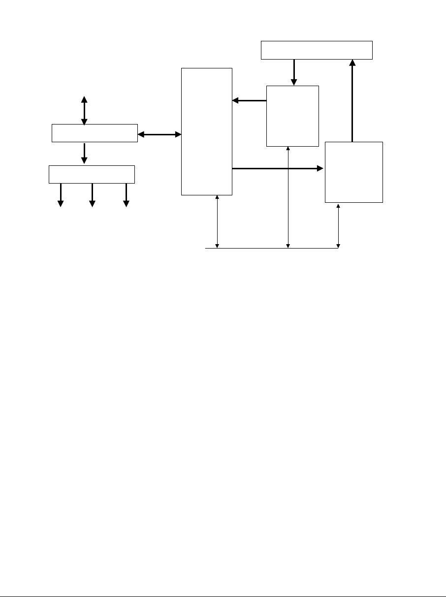
From/to tap
(RF + Vac)
V
Power Pickoff
Power Supply
TX RX DX
DX
AR250
RX
AR105
Receive
Module
TX
AR150
Transmit
Module
RX & TX Antennas
AC
RF
Control RS485 >
Figure 4-1: Block Diagram AX1255 Access Point.
4.3 TX Command Line Interface
The commands unique to the TX Module are:
1. Downstream Air Frequency
2. Downstream Enable
These will be explained here.
4.3.1 TX Login
The LOG Login command is required to establish one-to-one communications with a
particular Module. Because this is a bussed system, one and only one Module can
be active at any one time. Prior to the complete Login command, no responses or
echo backs will occur. Once logged into one Module, one-to-one communications
can occur. It is only necessary to log into a Module once to establish
communications.
*LOG<nnmm>, where nn = mm = {01, 02, … 7F} is the hexadecimal address of the
Module within the ARCell
Transceiver/Antenna unit and is entered twice, i.e., nn and mm are identical.
ARCXtend manual, August 2003 4-2

Note that the Login command begins with an asterisk (*), and the Module’s address
is repeated twice. Prior to Login, no Module is active, and no character echo back
will be received on the PC. Example, to log into the Transmit Module (AR150):
Type: *log0202 (all of which is hidden because it is not echoed)
AR150TX [02] (this is what the Module sends to indicate successful login)
The information above echoed by the addressed Module is: the Module type
(AR150), the function (TX = Transmitter), and the hex address (02).
The LOG command will automatically make any other active Module Quit (logout) if
it was previously enabled.
4.3.2 TX Downstream Air Frequency
The Downstream Air center Frequency is set within the 5.8 GHz band with the
command:
DA<nnnn>, where the frequency is in Megahertz.
The DA command is acknowledged with an “initializing” message during the actual
writing of internal processor registers, and the successful completion is
acknowledged with the message displaying the new value.
It must be given to both the TX Module and the DX Module.
Example, to set the Downstream frequency to 5735 MHz:
*log0202 [this typing is not echoed, not shown on the PC screen, the active module,
seeing the login, will logout]
AR150TX[02]>da5735
Initializing...
DA Downstream Air Output 5735 MHz
The Downstream Air frequency is the actual frequency used in the 5.8 GHz ISM
band, as would be seen by a spectrum analyzer. It is received by the CPE outdoor
transceiver which connects to the subscriber cable modem.
The available 18 values are in the Section on Frequency Planning.
IMPORTANT: Downstream Air Frequency must be set in BOTH the TX and the DX
modules, separately.
4.3.3 TX Title
The Title, or label, for the Access Point TX Module can be set.
It can be up to 3 lines of alphanumeric text and keyboard printable ASCII symbols,
with 32 characters per line.
All three Modules can accept a Title.
T<n><string>, where n = {0, 1, 2}
Notice that there is no space between the single-digit line number <n> and the
<string>. If there is one space, it is thrown away. Spaces in the title are OK.
ARCXtend manual, August 2003 4-3

A Title line ends with a carriage return.
Example, to set the following title:
*log0202 [this typing is not echoed, not shown on the PC screen]
AR150 Tx [02]
Enter up to 3 lines of text, beginning with T0, T1, or T2
T0 Pole #123 @ Main St. and 4th Ave
T1Strand mounted
T2 Pointing 300 degrees (west)
4.3.4 TX Banner Information
A quick way to establish the basic information about an Access Point is to request
the Banner Information.
1) Title
2) Downstream Air Frequency
3) Downstream enabled
Command:
B
Example, look at transmitter parameters:
*log0202 [this typing is not echoed, not shown on the PC screen]
AR150TX[02]>b
AR150 Transmitter Copyright (c) 2003 Arcwave, Inc.
Software Build Aug 13 2003 20:46:38
DA Downstream Air Output 5729 MHz
DE Downstream RF Enable NO
........ [factory default is series of dots]
........
........
4.3.5 TX Quit
The Quit command will end the session with the device that was logged in. It is
acknowledged with the phrase “logging off”.
Example:
Q
Logging off
ARCXtend manual, August 2003 4-4

4.3.6 TX Initialize
The Initialize command forces the software to initialize, also called a Software
Reboot or a Warm Start.
The Access Point Module will return to its last saved settings.
*log0202
AR150TX [02]
Initializing…
(no parameters are displayed)
4.3.7 TX Help
The Help command will cause the active Module to generate a list of allowed system
setup commands.
Invalid or incomplete entries will generate a response that starts with a question
mark and includes the valid entries that the CPU is expecting.
Example:
*log0202 [this typing is not echoed, not shown on the PC screen]
AR150TX[02]>h
List of commands...
*LOGxxxx Log into card
Q Quit
I Initialize
W[addr][data] Write EE Memory
R Read EE Memory
PI1xxxxxx PLL I,F,R,N Regs
T[0-2] text Write a Title line
S Status
B Banner
DAxxxx Downstream Air MHz
DE[Y/N] Downstream Enable
4.3.8 TX Downstream Enable
The Downstream Enable command allows RF power to be transmitted to the
antenna. The parameter is YES or NO.
YES is the normal state.
NO is the factory default to prevent accidental transmissions at the wrong frequency.
ARCXtend manual, August 2003 4-5

The command is:
DE<a>, where the alphabetic is Y (yes) or N (no)
DEy
DEn
Example:
AR150TX[02]>dey
DE Downstream RF Enable YES
4.3.9 TX Transmit Defaults
As shipped from the factory, the Transmit Module has the following default values:
DE=no (i.e., disabled)
DA=0000 MHz
T0=…..
T1=…..
T2=…..
4.3.10 TX Status
This is an engineering and manufacturing/repair command. It should not be used.
4.3.11 TX Read
This is an engineering and manufacturing/repair command. It should not be used.
4.3.12 TX Screen Session
The following series of examples contain actual screen captures to show a session
with the Transmit Module might progress. This session includes Engineering/Mfg
commands.
*log0202
AR150TX[02]>b
AR150 Transmitter Copyright (c) 2003 Arcwave, Inc.
Software Build Aug 13 2003 20:46:38
DA Downstream Air Output 5729 MHz
DE Downstream RF Enable NO
........
........
........
AR150TX[02]>da
? Value 1
ARCXtend manual, August 2003 4-6

? Valid Downstream Air Frequencies (MHz) are
5729 5735 5741 5747 5759 5765 5771 5777 5783
5789 5795 5807 5813 5819 5825 5831 5837 5843
LO STD: 5248 MMDS A: 5504 B: 5408
AR150TX[02]>da5735
Initializing...
DA Downstream Air Output 5735 MHz
AR150TX[02]>de
? Enable use deY(yes) or deN(no)
AR150TX[02]>dey
DE Downstream RF Enable YES
AR150TX[02]>b
AR150 Transmitter Copyright (c) 2003 Arcwave, Inc.
Software Build Aug 13 2003 20:46:38
DA Downstream Air Output 5735 MHz
DE Downstream RF Enable YES
........
........
........
AR150TX[02]>h
List of commands...
*LOGxxxx Log into card
Q Quit
I Initialize
W[addr][data] Write EE Memory
R Read EE Memory
PI1xxxxxx PLL I,F,R,N Regs
T[0-2] text Write a Title line
S Status
B Banner
ARCXtend manual, August 2003 4-7

DAxxxx Downstream Air MHz
DE[Y/N] Downstream Enable
AR150TX[02]>i
Initializing...
AR150TX[02]>q
Logging off
4.4 RX Command Line Interface
Commands unique to the RX Module are:
a) Upstream Air Frequency
b) Upstream Enable
c) Upstream Attenuate
4.4.1 RX Login
This command is the same for the Receiver, but uses the Receive Module address
(03 hex).
4.4.2 RX Title
This command is the same for the Receiver.
The information in the Title can be different for all three modules.
4.4.3 RX Quit
This command is the same for the Receiver.
4.4.4 RX Upstream Frequency
The AR105 RX Receive Module must have its Upstream receive air and cable
frequencies set.
The cable frequency is pre-assigned by the operator.
Given the cable frequency, the received air frequency is a choice of two (lower and
upper) air frequencies in the 5.250 to 5.350 GHz frequency band. Therefore once
the cable upstream center frequency is set, the same command can set the air
frequency.
The command for Upstream Frequency is entered as decimal Megahertz plus an L
(Low or lower) or H (High or upper) suffix.
The command is:
UF<nn.na>, where nn.n is the frequency in MHz and “a” is the alphabet L or H.
ARCXtend manual, August 2003 4-8

Example, to set the Upstream RX to 6.4 MHz, with high 5.3 GHz band channel:
*log0303 [this typing is not echoed, not shown on the PC screen]
AR105RX[03]>uf6.4L
Initializing...
UF Upstream Frequency 6.4L MHz
The Table in the Section on Frequency Planning shows the cable modem frequency
and the corresponding 5.3GHz-band air frequencies.
Note: MSO may have a different Upstream frequency. If so, select nearest one in
the above table. The AX1255 will track the actual frequency.
4.4.5 RX Upstream Attenuation in dB
The Cable System needs to receive a signal from the ARCXtend Access Point
equivalent to what a standard wired cable modem at that same point in the CATV
system would produce. To achieve this, the Upstream attenuation can be set to an
appropriate value in decibels.
The module contains a programmable attenuator, which can be controlled over a 30
dB range in 2 dB steps, thus providing a 30 dB range in gain.
UdB<nn>, where nn is the value in decibels, and is an even number between 0 and
30.
Example, to set the attenuation to 12 dB:
*log0303 [this typing is not echoed, not shown on the PC screen]
AR105RX[03]>udb12
UDB Upstream Attenuation 12 dB
4.4.6 RX Upstream Enable
A method to enable or disable the wireless upstream signal path into the cable
upstream channel. In normal operation this will be set to “Enable” which is the
default. To disconnect the wireless upstream channel from the cable system
upstream channel, set to “Disable”.
In Disable mode all other module functions remain operating.
The command is:
UE<a>, where the alphabetical is y (yes) or n (no).
UEY (Upstream Enable - YES)
UEN (Upstream Enable - NO)
The factory default is NO.
Thus a unit inadvertently attached to a cable system without pre-configuration will
NOT generate RF into the cable system, nor generate RF into the air.
ARCXtend manual, August 2003 4-9

4.4.7 RX Banner Information
The banner command for the RX Module is the same, but the information displayed
is different.
B
1) Title (3 lines)
2) Upstream EIA frequency
3) Upstream Attenuator setting
4) Upstream Enable (Y/N status)
Example:
AR105RX[03]>b
AR105 Receiver Copyright (c) 2003 Arcwave, Inc.
Software Build Aug 13 2003 20:10:11
UF Upstream Frequency 19.2L MHz
UE Upstream RF Enable YES
UDB Upstream Attenuation 12 dB
........
........
........
4.4.8 RX Module Help
The HELP command for the Receive Module AR105 delivers the following list of RX
commands:
Login
Quit
Initialize
Write
Read
Phase Lock Loop settings
Title
Status
Banner
Upstream Frequency
Upstream Enable
Upstream Attenuator
ARCXtend manual, August 2003 4-10

Example:
AR105RX[03]>h
List of commands...
*LOGxxxx Log into card
Q Quit
I Initialize
W[addr][data] Write EE Memory
R Read EE Memory
PI1xxxxxx PLL I,F,R,N Regs
T[0-2] text Write a Title line
S Status
B Banner
UFxx.x[H/L] Upstream Freq HI/LO
UE[Y/N] Upstream Enable Y/N
UDBxx Upstream Attenuation
4.4.9 RX Module Status
This is an engineering and manufacturing/repair command. It should not be used.
4.4.10 RX Read
This is an engineering and manufacturing/repair command. It should not be used.
4.4.11 RX Module Session
*log0303
AR105RX[03]>b
AR105 Receiver Copyright (c) 2003 Arcwave, Inc.
Software Build Aug 13 2003 20:10:11
UF Upstream Frequency 19.2L MHz
UE Upstream RF Enable YES
UDB Upstream Attenuation 12 dB
........
........
........
AR105RX[03]>h
*LOGxxxx Log into card
ARCXtend manual, August 2003 4-11

Q Quit
I Initialize
W[addr][data] Write EE Memory
R Read EE Memory
PI1xxxxxx PLL I,F,R,N Regs
T[0-2] text Write a Title line
S Status
B Banner
UFxx.x[H/L] Upstream Freq HI/LO
UE[Y/N] Upstream Enable Y/N
UDBxx Upstream Attenuation
AR105RX[03]>b
AR105 Receiver Copyright (c) 2003 Arcwave, Inc.
Software Build Aug 13 2003 20:10:11
UF Upstream Frequency 19.2L MHz
UE Upstream RF Enable YES
UDB Upstream Attenuation 12 dB
........
........
........
AR105RX[03]>uf
? Use Frequency plus L,H (ie 6.4L)
6.4 9.6 12.8 16.0 19.2 22.4 25.6
28.8 32.0 35.2 38.4 41.6 44.8 48.0
AR105RX[03]>uf6.4l
Initializing...
UF Upstream Frequency 6.4L MHz
AR105RX[03]>ue
? Enable use ueY(yes) or ueN(no)
ARCXtend manual, August 2003 4-12

AR105RX[03]>uey
UE Upstream RF Enable YES
AR105RX[03]>udb
? Attenuator: 0 to 30 dB (2dB steps)
AR105RX[03]>udb12
UDB Upstream Attenuation 12 dB
AR105RX[03]>b
AR105 Receiver Copyright (c) 2003 Arcwave, Inc.
Software Build Aug 13 2003 20:10:11
UF Upstream Frequency 6.4L MHz
UE Upstream RF Enable YES
UDB Upstream Attenuation 12 dB
........
........
........
AR105RX[03]>uen
UE Upstream RF Enable NO
AR105RX[03]>
4.5 DX Command Line Interface
The Digital Cable Extender (DX) Module commands are described in this section.
Commands unique to the DX Module are:
a) Downstream Air Frequency
b) CATV Channel
4.5.1 DX Downstream Help
The DX HELP command produces the following list of commands:
Login
Quit
Initializie
ARCXtend manual, August 2003 4-13

Write
Read
Phase Lock Loop
Title
Status
Banner
Downstream Cable EIA
Downstream Air
AGC control
DAC output
MT control
Many of these above commands are for Engineering and Manufacturing/Repair use
only.
Example:
AR250DX[01]>h
List of commands...
*LOGxxxx Log into card
Q Quit
I Initialize
W[addr][data] Write EE Memory
R Read EE Memory
PI1xxxxxx PLL I,F,R,N Regs
T[0-2] text Write a Title line
S Status
B Banner
DCExx CATV EIA Input Chan
DAxxxx Downstream Air MHz
Ax AGC control
Vcddd DAC Output
M[reg][data] MT control
4.5.2 DX Quit
The DX Quit command is the same.
ARCXtend manual, August 2003 4-14

4.5.3 DX Downstream Cable Channel
The Downstream Cable EIA (DCE) Channel is the channel on which the DOCSIS
cable modem downstream signal is being sent from the CMTS at the head end. It is
set in the ARCXtend Access Point with the standard EIA channel numbers.
*DCE<nnn>, where nnn is an EIA channel number from 23 to 94 and 100 to 138.
Note: In the EIA standard, channels 94 and 100 are adjacent, so there is no gap in
frequency.
The system response to the command is the word “initializing” followed by a series
of internal registers that the CPU is writing to.
Successful completion is noted by displaying the result achieved, plus the actual
ARCXtend center frequency for that channel.
The corresponding 6 MHz channel center frequency from the cable-to-AX1255 and
from AX3155-to-modem is given in the Table below.
Example, to set the Downstream Cable EIA Channel to channel 23:
*log0101 [this typing is not echoed, not shown on the PC screen, the active module,
seeing the login, will logout]
AR250DX[01]>dce23
Initializing...
MT2050 Write Reg 0x01 Data 0xAD
MT2050 Write Reg 0x02 Data 0x1C
MT2050 Write Reg 0x03 Data 0xA8
MT2050 Write Reg 0x04 Data 0x00
MT2050 Write Reg 0x05 Data 0x63
MT2050 Write Reg 0x06 Data 0x10
MT2050 Write Reg 0x08 Data 0x29
MT2050 Write Reg 0x0A Data 0x05
MT2050 Write Reg 0x0F Data 0x0F
MT2050 Write Reg 0x10 Data 0x24
DCE CATV Input US Channel 23 (219 MHz)
4.5.4 DX Downstream Air Frequency
Both the TX and DX module must also be programmed with the DA command and
the same frequency.
The command context is the same as for the TX module, but logging into the DX
Module.
ARCXtend manual, August 2003 4-15

The response to the DA command is “initializing” followed by a list of registers that
the CPU is writing.
Successful completion is displayed by the actual frequency achieved as “air output”.
Example:
AR250DX[01]>da5789
Initializing...
MT2050 Write Reg 0x01 Data 0xAD
MT2050 Write Reg 0x02 Data 0x1C
MT2050 Write Reg 0x03 Data 0xA8
MT2050 Write Reg 0x04 Data 0x00
MT2050 Write Reg 0x05 Data 0x63
MT2050 Write Reg 0x06 Data 0x10
MT2050 Write Reg 0x08 Data 0x29
MT2050 Write Reg 0x0A Data 0x05
MT2050 Write Reg 0x0F Data 0x0F
MT2050 Write Reg 0x10 Data 0x24
DA Air Output 5789 MHz (250->150 IF 461 MHz LO: 505 MHz)
4.5.5 DX Initialization
The DX INITIALIZE command resets the software and rewrites the registers. The
command is:
i
The response is the word “initializing” followed by a series of registers being written.
Successful completion is indicated by the prompt:
AR250DX[01]
Example:
AR250DX[01]>i
Initializing...
MT2050 Write Reg 0x01 Data 0xAD
MT2050 Write Reg 0x02 Data 0x1C
MT2050 Write Reg 0x03 Data 0xA8
MT2050 Write Reg 0x04 Data 0x00
MT2050 Write Reg 0x05 Data 0x63
MT2050 Write Reg 0x06 Data 0x10
MT2050 Write Reg 0x08 Data 0x29
ARCXtend manual, August 2003 4-16

MT2050 Write Reg 0x0A Data 0x05
MT2050 Write Reg 0x0F Data 0x0F
MT2050 Write Reg 0x10 Data 0x24
AR250DX[01]>
4.5.6 DX Status
This is an engineering and manufacturing/repair command. It should not be used.
4.5.7 DX AGC Control
This is an engineering and manufacturing/repair command. It should not be used.
4.5.8 DX MT Control
This is an engineering and manufacturing/repair command. It should not be used.
4.5.9 DX DAC Output Read Command
This is an engineering and manufacturing/repair command. It should not be used.
4.5.10 DX Read
This is an engineering and manufacturing/repair command. It should not be used.
4.5.11 DX Write
This is an engineering and manufacturing/repair command. It should not be used.
4.5.12 DX Screen Session
The following series of examples contain actual screen captures to show how the
DX Module AX250 responds to various input.
*log0101
AR250DX[01]>h
List of commands...
*LOGxxxx Log into card
Q Quit
I Initialize
W[addr][data] Write EE Memory
R Read EE Memory
PI1xxxxxx PLL I,F,R,N Regs
T[0-2] text Write a Title line
S Status
B Banner
DCExx CATV EIA Input Chan
ARCXtend manual, August 2003 4-17

DAxxxx Downstream Air MHz
Ax AGC control
Vcddd DAC Output
M[reg][data] MT control
AR250DX[01]>b
Digital Cable Extender Copyright (c) 2003 Arcwave, Inc.
Software Build Aug 13 2003 20:50:47
DCE CATV Input US Channel 0 ( 0 MHz)
DA Air Output 0 MHz (250->150 IF 0 MHz LO: 44 MHz)
........
........
........
AR250DX[01]>dce
? Value 1
? Valid CATV Input Channels are 23-94 and 100-138
AR250DX[01]>dce23
Initializing...
MT2050 Write Reg 0x01 Data 0xAD
MT2050 Write Reg 0x02 Data 0x1C
MT2050 Write Reg 0x03 Data 0xA8
MT2050 Write Reg 0x04 Data 0x00
MT2050 Write Reg 0x05 Data 0x63
MT2050 Write Reg 0x06 Data 0x10
MT2050 Write Reg 0x08 Data 0x29
MT2050 Write Reg 0x0A Data 0x05
MT2050 Write Reg 0x0F Data 0x0F
MT2050 Write Reg 0x10 Data 0x24
DCE CATV Input US Channel 23 (219 MHz)
AR250DX[01]>da
? Value 1
ARCXtend manual, August 2003 4-18

? Valid Downstream Air Frequencies (MHz) are
5729 5735 5741 5747 5759 5765 5771 5777 5783
5789 5795 5807 5813 5819 5825 5831 5837 5843
AR250DX[01]>da5789
Initializing...
MT2050 Write Reg 0x01 Data 0xAD
MT2050 Write Reg 0x02 Data 0x1C
MT2050 Write Reg 0x03 Data 0xA8
MT2050 Write Reg 0x04 Data 0x00
MT2050 Write Reg 0x05 Data 0x63
MT2050 Write Reg 0x06 Data 0x10
MT2050 Write Reg 0x08 Data 0x29
MT2050 Write Reg 0x0A Data 0x05
MT2050 Write Reg 0x0F Data 0x0F
MT2050 Write Reg 0x10 Data 0x24
DA Air Output 5789 MHz (250->150 IF 461 MHz LO: 505 MHz)
AR250DX[01]>i
Initializing...
MT2050 Write Reg 0x01 Data 0xAD
MT2050 Write Reg 0x02 Data 0x1C
MT2050 Write Reg 0x03 Data 0xA8
MT2050 Write Reg 0x04 Data 0x00
MT2050 Write Reg 0x05 Data 0x63
MT2050 Write Reg 0x06 Data 0x10
MT2050 Write Reg 0x08 Data 0x29
MT2050 Write Reg 0x0A Data 0x05
MT2050 Write Reg 0x0F Data 0x0F
MT2050 Write Reg 0x10 Data 0x24
AR250DX[01]>q
ARCXtend manual, August 2003 4-19
5 Multiples Access Points
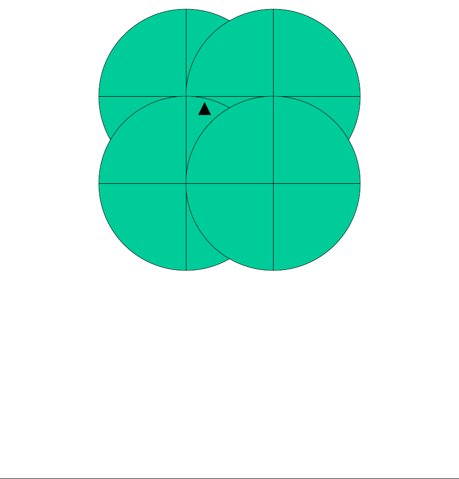
As discussed elsewhere, the system supports a frequency reuse pattern.
5.1 Frequency Planning
Frequency planning may involve multiple Access Points. Taking a “worst-case”
where there are four pole-mounted Access Points in close proximity, as in Figure 5-
1.
The subscriber, shown as a triangle in the Figure, can be served from three of the
Access Points, so the installer should point the antenna toward the Access Point
with the best line of sight. If several have line of sight, then point to the Access Point
with the least traffic.
Fa
Fa
Fb
Fb
Fa
Fa
Fb
Fb
Fa
Fa
Fb
Fb
Fa
Fa
Fb
Fb
Figure 5-1: A multi-cell configuration.
5.2 Mounting & Site Planning
Some of the topics to consider is doing a site plan are:
a) Best location & direction to reach multiple subscribers with line of sight
b) Wind conditions at that location
c) Strand vs. Pole mounting
d) Cable vs. local powering
ARCXtend manual, August 2003 5-1

e) Frequency plan for that neighborhood
f) Cable system tap to use, based on existing and future traffic.
ARCXtend manual, August 2003 5-2

6 Fault Localization
Any fault in the system has to go through some logical filtering to try to localize the
problem. This section assumes the installation used to work OK, and that someone
has already gone through this filtering and now suspects the wireless portion of the
system. Thus, for example if it is a user complaint, the user has already restarted
their modem, checked IP addresses, verified authorization database, etc.
6.1 Only one user impacted
If the modem indicates it has poor or no RF input:
1. Check the power inserter.
2. Check the power at the outdoor unit end. Broken cables are common.
3. Visually inspect the cable. Kinks, staples pinching the cable, slashed
insulation, abrasions (from tree branches), etc. can ruin the ability of
coaxial cable to carry the signal.
4. Inspect outdoor connectors and grounding at the building entrance. Water
ingress is common.
5. Visually check the antenna alignment. Wind, tree branches and other
things may have miss-aligned it.
6. Tree growth and seasonal leafing can obstruct the RF signal.
7. Interview the customer about recent activity.
If none of the above fix the problem, and if the modem indicates that the RF signal is
OK, but no service, then the upstream path may have a fault, causing the CMTS at
the head end to not send data. The outdoor unit’s transmitter may have failed.
Connect a spare outdoor unit temporarily and see if the problem clears. The modem
is already authenticated and authorized, so subscriber service should start
automatically. If the fault clears, mount the new unit permanently and send the old
one for repair.
If the link is intermittent, and none of the above items seem to be causing the
problem, then there may be interference coming into the outdoor unit. If a 5 GHz
802.11a WLAN is suspected, it can be detected with either an 802.11a client card on
a PC, or with a spectrum analyzer. To use a spectrum analyzer, place a tap
between the coaxial cable and the cable modem, between the cable modem and the
power inserter. Connect the spectrum analyzer to the tap and observe the 5 GHz
band when the modem is showing problems.
If interference is detected or suspected, rotate the outdoor antenna/transceiver unit 5
and 10 degrees in one direction and then the other. Often one of these positions will
place the interferer in an antenna null while still keeping the main antenna lobe
pointed at the Access Point
ARCXtend manual, August 2003 6-1

6.2 Multiple Users Impacted
If multiple users are impacted and they are clustered together, and other users
served by this one Access Point are OK, then consider the following sources of the
problem:
1. Misalignment
2. Antenna damage
3. Interference
If the cluster of users is located at one edge of the Access Point’s beamwidth, then
check the Access Point alignment. A recent storm may have changed the alignment
or degraded its performance. A utility worker on the pole may have accidentally
bumped it out of alignment.
The Access Point is a robust unit and tested to severe weather conditions.
Nevertheless, a storm could have damaged the radome covering the antenna. A
utility worker on the pole could also have accidentally damaged the radome and
antenna.
If interference is suspected, the general direction can be estimated from a map with
the locations of the subscribers and vectors drawn for the direction of their outdoor
unit pointing to the Access Point.
Confirming this requires a directional antenna and a spectrum analyzer. Pointing to
the suspected source of the interference, the spectrum analyzer will help determine
the extent of the interference -- its power level, bandwidth, etc. If it is consistent,
day-to-day, then it may be appropriate to move the entire sector to another
downstream frequency within the 5.8 GHz band.
If only a couple of users are impacted, and there is an alternative Access Point for
them to point to, then rotate their antennas to the new Access Point.
6.3 Entire Sector
A sudden loss of a whole sector may be caused by a hardware failure:
a) Cable to the Access Point
b) Power to the Access Point
c) Complete AP misalignment
d) Internal failure of the Access Point
e) Interference incoming to the Access Point
Remember, just like the wired modems, if the Downstream has a hardware failure,
all the modems will have lost communication in both directions. Subscribers looking
at their modem’s user interface will see no incoming signal.
Internal failures of the AP are rare, but when they do happen the fastest way to
restore service is to replace the entire unit with a pre-configured spare. The old unit
goes back to the shop for testing and replacement of the failed module.
ARCXtend manual, August 2003 6-2

Lightning surges can cause any electronic system to fail. It is assumed that in
lightning regions the AP has been mounted adjacent to a tap which contains surge
protection.
Causes of AP misalignment include:
a) a cherry-picker bucket bumping it or its mounting bracket
b) a utility worker using it as a foothold
c) vandalism.
Strand-mounted APs are not likely to be used as a foothold, but are still subject to
bucket-bumps and vandalism.
Interference at the Access Point can be caused by a new radio turning on in the 5.3
GHz band and being pointed mostly toward the AP. If the offending unit can be
located quickly, the owner will often cooperate with finding a mutually satisfactory
solution. Usually the small laptop computer types of WLAN equipment have
omnidirectional antennas and will not interfere with the AP. It usually has to be a
fixed radio with an outdoor high-gain antenna. Such antennas are often very visible
just by scanning nearby rooftops with binoculars.
ARCXtend manual, August 2003 6-3
7 Replacing Failed Access Point
The replacement must be configured exactly like the failed unit. This is normally
done in the shop prior to field installation by downloading a saved file.
Install a spare pair of brackets below and tight up against the existing mount and
align them exactly like the Access Point brackets, as shown in Figure 7-1. This
spare bracket will both prevent the AP from slipping on the pipe as the bolts are
loosened and will act as an pointer to align the new AP as well as supporting it
vertically as it is installed.
Pivot bracket
AP bracket
Figure 7-1: Temporary pivot bracket exactly aligned with AP bracket.
Take a ruler and measure and write down the distance of the top of the antenna
from and bracket and the bottom from the bottom bracket, as in Figures 7-2 & 7-3.
Any difference represents the amount of the antenna downtilt.
ARCXtend manual, August 2003 7-1
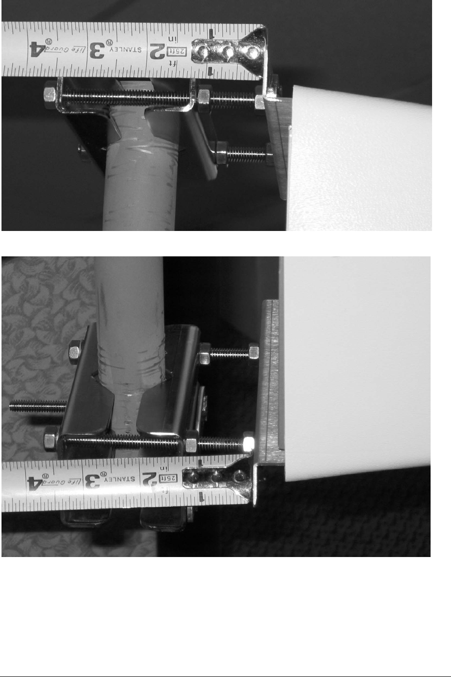
Figure 7-2: Measuring tilt at top of pipe mount.
Figure 7-3: Measuring tilt at bottom of pipe mount.
To replace the failed unit, follow this procedure:
1) Remove power, if locally sourced.
2) Untape and disconnect the coaxial cable
ARCXtend manual, August 2003 7-2

3) If pole mounted, then add a spare pair of brackets under the AP,
aligned exactly the same. This is a temporary guide for the new unit
(see Figure 7-1).
4) Measure & record the top and bottom to determine downtilt, if any.
(Figures 7-2 & 7-3)
5) If strand mounted, mark the holes on the bracket that have the AP
bolts, then unbolt the AP from the strand brackets. Be sure to leave
the strand brackets undisturbed.
6) Install the new AP, using the above markings
7) Insert the coaxial connector and tape it for weather resistance.
8) Insert local power, if needed, and tape for weather.
9) Verify service has been restored.
7.1 Access Point - Strand Mount
Do not remove the strand-mount brackets. They determine the antenna alignment.
If the AP is locally powered, remove the power connector before the coaxial
connector.
Remove the bolts holding the AP to the brackets and install the new AP.
ARCXtend manual, August 2003 7-3

ARCXtend manual, August 2003 7-1
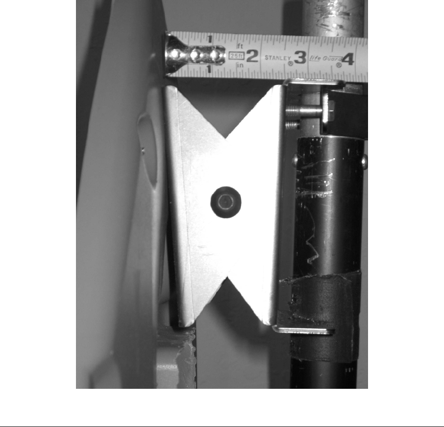
8 Replacing a Failed Subscriber Unit
If it has been determined that the subscriber’s outdoor unit failed, then the follow this
procedure:
1) Bolt a spare bracket under but touching the existing bracket, and orient it
exactly the same.
2) Measure the down tilt. A simple way is to use a ruler and write down the
difference in distance between the upper and lower edges of the antenna
brackets (see Figure 8-1).
3) Remove the coaxial cable, which also powers the unit.
4) Remove the outdoor unit
5) Install the new unit using the above markings and measurements
6) Attach the coaxial cable and tape it for weather
7) Verify service has been restored.
Figure 8-1: Measure CPE top tiltdown.
ARCXtend manual, August 2003 8-1

ARCXtend manual, August 2003 8-2

9 Specifications
9.1 AX1255 ARCXtend Access Point
Transceiver
Channel Capacity Transmit: 18, 6.0 MHz Channels
Receive: 12, 3.2 MHz Channels
Downstream Transmit Input
Signal Level Range
0 to +25 dBmV
RF Frequency Range TX: 5.725 to 5.850 GHz
RX: 5.250 to 5.350 GHz
IF Frequency Range 200 to 860 MHz (DS); 5 to 42 MHz (US)
Downstream Airlink Data Rate
31.0 Mbps (64 QAM)
Upstream Airlink Data Rate 5.12 Mbps (QPSK) - DOCSIS 1.0/1.1
10.24 Mbps (16 QAM) - DOCSIS 1.0/1.1
Maximum Transmit Output
Power
+36 dBm EIRP
Receiver Noise Figure 3.5 dB
Adjacent Channel Rejection Greater than 40 dB
Antenna
Horizontal Beamwidth (–3 dB)
Transmit Gain
Receive Gain
90 degree
14 dBi
16 dBi
Mechanical, System, and
Regulatory
Input Power 60 or 90VAC (CATV Line)
+24VDC (Local)
Operating Power +24VDC
Optional Redundant Power Supplies
Operating Temperature Range –30°C to +60°C (-22°F to +140°F)
Operating Humidity 5% to 95% non-condensing
Management
Local Craft Interface (LCI)
F-Type Monitor Port
ARCXtend manual, August 2003 9-1

Protocols DOCSISTM 1.1 Compatible
Range Up to 2 miles Line of Sight (LOS) using
64QAM
Regulatory FCC, IC (Canada)
Mounting Pole, Mast/Pipe, and Strand
Dimensions 41” x 7” x 5”
Weight 13 lbs.
9.2 AX3155 Customer Premise Antenna/Transceiver
Specifications
Transceiver
Channel Capacity Transmit: 12, 3.2 MHz Channels
Receive: 20, 6 MHz Channels
RF Frequency Range 5.725 to 5.850 GHz (RX);
5.250 to 5.350 GHz (TX)
IF Frequency Range 5 to 42 MHz (US); 425 to 550 MHz (DS)
Downstream Receive Output
Signal Level Range
-15 dBmV to +15 dBmV
Downstream Airlink Data Rate
31.0 Mbps (64 QAM)
Upstream Airlink Data Rate 5.12 Mbps (QPSK)
10.24 Mbps (16 QAM)
Maximum Transmit Output
Power
+30 dBm EIRP
Receiver Noise Figure 3.0 dB
Antenna
Downstream Beamwidth (–3
dB)
Upstream Beamwidth (–3 dB)
Transmit Gain
Receive Gain
12 degree
30 degree
14 dBi
22 dBi
System
Power Requirements 120 VAC and 220/230VAC; 18 Watts
ARCXtend manual, August 2003 9-2

(Wall Mounted AC Adaptor)
Operating Power 12VDC
(DC Inserter provides power over IF
Cable)
Operating Temperature Range –30°C to +60°C (-22°F to +140°F)
Operating Humidity 5% to 95% non-condensing
Management Remote Status and Performance
Monitoring via Cable Modem
Protocols DOCSIS 1.1 Compatible
Range Up to 2 miles Line of Sight (LOS) using
64QAM
Regulatory FCC, IC (Canada)
Mounting 1-1/4” to 2-3/8” OD Pipe Mount
Dimensions 14-5/8” x 14-5/8” x 2-3/8”
Weight 5.1 lbs.
ARCXtend manual, August 2003 9-3
10 Appendix A: Radio Frequency Basics
The Section covers introductory information on radio frequencies (RF) for those
who have not had to deal with RF in an outdoor environment before.
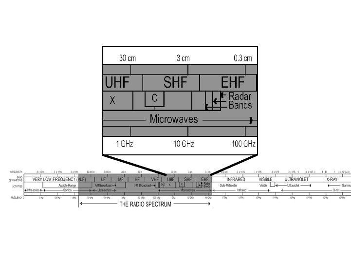
10.1 The Electromagnetic Spectrum
The electromagnetic waves all have similar physical behavior and their uses
range from AM radio broadcast stations at the low frequencies to TV
broadcasting frequencies, through microwave frequencies and then on to visible
light and X-Rays. These are illustrated in Figure 10-1.
Figure 10-1: The electromagnetic spectrum
Every country has its own assignment of frequency usage, called the Frequency
Allocation Table. The United Nations has committees that try to coordinate
usage within Regions, but each country has the right to “do its own thing”. The
US is in a Region that covers all the Americas (North, Central & South), and
there is a lot of commonality within the Region.
The US Frequency Allocation Table has been put in a chart form, shown in
Figure 10-2. The TV and the 5-GHz bands are highlighted with circles.
The 5-GHz-Band portion of that chart is shown in Figure 10-3. Notice that
segments are allocated to satellite communications, to amateur radio usage
(hams), to radio-location and radio-navigation systems. The location/navigation
category includes radar.
The chart is formatted so that users with higher priority are on top of users with
lesser priority. Unlicensed users have the least priority. In fact, every product
ARCXtend manual, August 2003 10-1
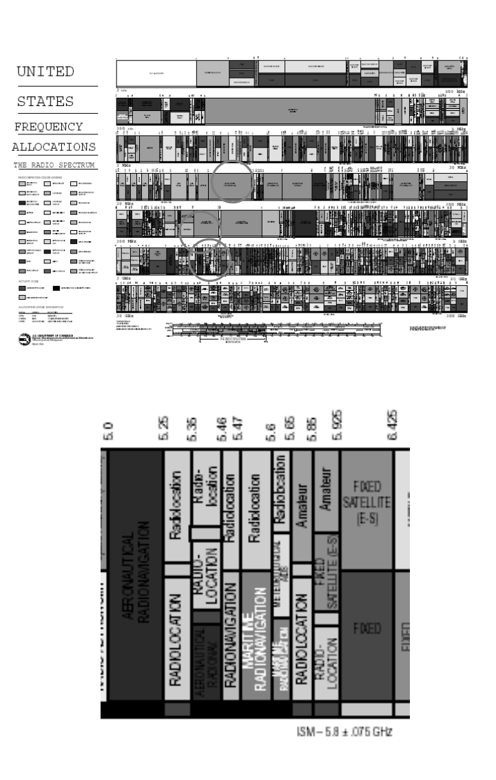
sold that uses the unlicensed bands must contain a notification to the buyer that
the product must accept interference from other users. Think about how different
this is from a licensed band, like a TV station, where no one is permitted to
interfere with the TV station’s broadcast.
Figure 10-2: The US Frequency Allocation Chart.
Figure 10-3: Frequency allocation in the 5 GHz band.
ARCXtend manual, August 2003 10-2
The frequencies set aside for Industrial, Scientific and Medical (ISM) use have
become known as the unlicensed bands, or license-free bands. In many
countries the ISM band is still a licensed band, but used for the same purposes.
For example, the service provider may be licensed to offer service in the ISM
band, even though a user buys a PC card at a store, is not licensed, but is a
subscriber to the service.
10.2 FCC Rules for use of ISM band
The Federal Communications Commission (FCC) has set down Rules and
Regulations for using the ISM bands.
There are many ISM bands, but the ones that have been most popular are:
a) 902 - 928 MHz
b) 2.400 - 2.4835 GHz
c) 5 GHz
The 2.4 GHz band has gained popularity through the emergence of the IEEE
802.11b/g devices, also called Wi-Fi. These are in laptop computers, PDAs and
other devices. Users link their laptops to Wi-Fi Access Points, often called “Hot
Spots”.
The 5 GHz band is also gaining popularity with IEEE 802.11a devices, but some
lab tests have shown that 802.11g devices outperform the 802.11a, and these
have cast doubt over the growth of the 802.11a devices.
Part 15 of the FCC Rules and Regulations dictate most of the RF characteristics
of the unlicensed devices:
1. Frequency band
2. Transmitter power (Intentional radiation)
3. Out-of-band emissions (Unintentional radiation)
4. Antenna gain/directionality
5. Method of measuring and other parameters
The transmitter power and sub-band frequencies are shown in Figure 10-4.
ARCXtend manual, August 2003 10-3
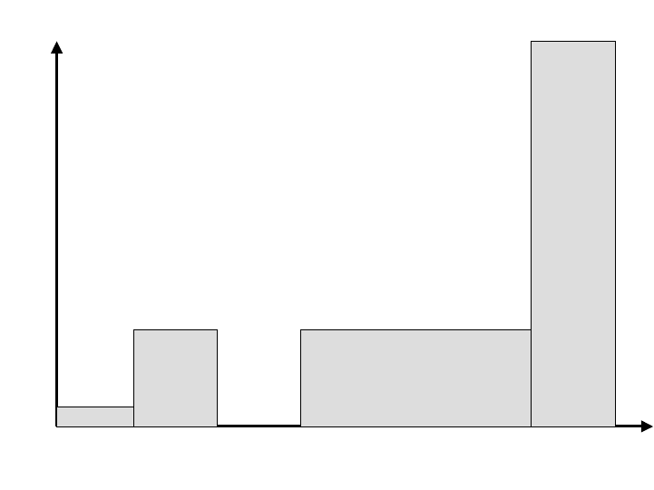
50 mW
Indoor
only
5.15 5.25 5.35 5.47 5.725 5.825
Frequency (GHz)
250 mW 250 mW
FCC proposal May03
1000 mW
Transmitter Power
Figure 10-4: Rules for 5 GHz Frequency Band.
The FCC’s proposed rule making of May 2003 opens the 5.47-5.725 GHz band
to ISM usage. This FCC proposal closely aligns the US band with the European
band usage. This common set of Rules is expected to achieve world-wide
acceptance.
Notice that the lower part of the band, 5.15-5.25 GHz, is limited to indoor use.
This is why the ARCell radios only use the 5.25 –5.35 GHz part of the lower sub-
band in the Upstream.
The high band, 5.725 – 5.825 GHz is allowed to use higher powers (1 Watt) and
the ARCell system uses this in the downstream path.
10.3 Line of Sight
All RF is attenuated by the materials in our environment:
1) Metal
2) Bricks and other building materials
3) Rain and bodies of water
4) Trees and other foliage
Most car antennas are outside the car because the car’s metal shell attenuates
radio broadcasts.
Most people who have tried listening to their FM radio at their desk have
experienced the loss of signal inside a commercial building.
Rain, fog, lakes and rivers all have their effects on RF.
ARCXtend manual, August 2003 10-4
Trees and other foliage contain a lot of water and therefore also attenuate the RF
signal.
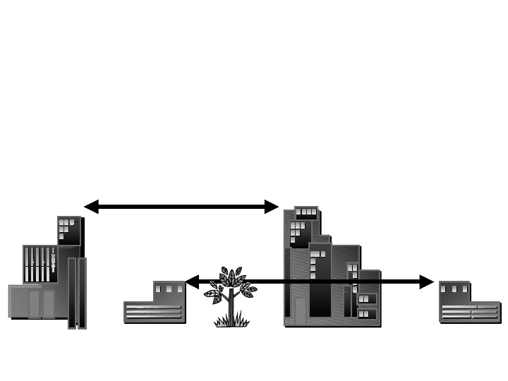
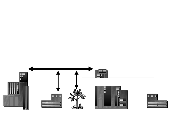
So the easiest approach to making good quality radio links is to have an
unobstructed line of sight between the transmitter and receiver, as illustrated in
Figure 10-5.
LOS
NLOS
X
NLOS
X
Figure 10-5: Line of Sight (LOS) and Non-LOS.
This does not mean that RF cannot penetrate buildings, or that it cannot bounce
off buildings and work its way to the receiver. It just means that such
arrangements require a lot of RF skill and experience to make them work.
It has also become popular in the wireless industry to talk of Near-Line-of-Sight
(NLOS). Again, radio waves do funny things when they pass over the edge of an
obstruction, but it takes a lot of experience with RF to predict the results.
One rule of thumb is to clear such objects by some extra room. Good
communications links clear objects in the middle of the link by 10-15 feet at this 5
GHz band. This is called the Fresnel Zone clearance, as illustrated in Figure 10-
6.
ARCXtend manual, August 2003 10-5
LOS
Fresnel Zone clearances
Figure 10-6: Line of Sight (LOS) plus some clearance.
10.4 Link Budgeting
This section is intended to give an overview of what an RF engineer has to
consider in determining the expected performance of an RF link.
The Link Budgeting starts with the output of a transmitter power amplifier. That
signal goes through a cable to the antenna. The antenna radiates it in a certain
pattern. It then travels through the air, where there may be additional attenuation
from rain. It finally arrives at the Receive antenna, down a cable, and into the
receiver itself. The receiver is usually rated for its “Sensitivity” at a certain bit
error rate. Any signal larger than that is assumed to have been received without
error.
The difference between the received signal and the Receive Sensitivity is the
margin for error, called Fade Margin.
A typical calculation of Fade Margin is:
Access Point Power amplifier output = 20 dBm
Access Point Transmit antenna gain = 14 dBi
Free Space Path Loss (2 miles @ 5 GHz)= 117 dB
Rain fade = 1 dB
CPE Transceiver Receive antenna gain = 22 dBi
CPE Transceiver Gain = 38 dB
ARCXtend manual, August 2003 10-6
Cable loss = 1 dB
Fixed pad at modem = 20 dB
Input to Cable Modem= --45 dBm=+4 dBmV
Note: 0 dBm @75Ω=+49 dBmV
In the above example, the received signal is –+4 dBmV.
The typical6 Cable Modem Receive Sensitivity is –15 dBmV to +15 dBmV at 64
QAM, so the Fade Margin is 4+15=19 dB.
Links are generally considered to be good with 10 or 20 dB Fade Margin, so this
is excellent.
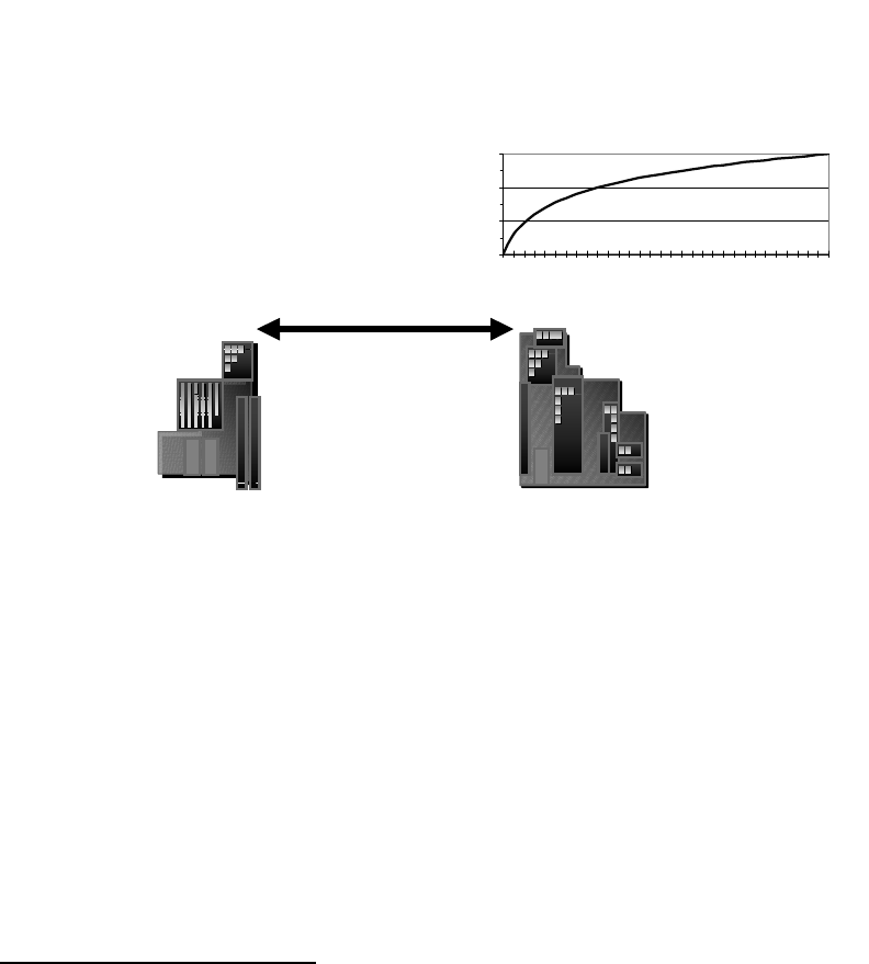
The Free Space Path Loss comes from the formula in Figure 10-7.
Loss5GHz band=112 + 20*log(miles)
LOSS
Loss (dB)
100.0
110.0
120.0
130.0
0.25
1.25
2.25
3.25
4.25
5.25
6.25
7.25
Distance (Miles)
Figure 10-7: Free Space Path Loss at 5GHz.
10.5 Availability
Classical microwave formulas also address the Availability of a link. The
Availability is the percent of the time the link meets its performance specification,
usually measured in Bit Error Rate or Packet Error Rate. Measured on a yearly
basis, the Availability is simply the percent time the link does not have an
Outage. An Outage is usually a 10-second interval in which the performance
falls below a set level.
6 D-Link model 200 data sheet from www.dlink.com
ARCXtend manual, August 2003 10-7

Table 8-1: Availability and Outage
Availability Outage % Outage Time
99.9% 0.1% 9 hours/year
99.99% 0.01% 1 hour/yr
99.999% 0.001% 5 minutes/yr
The Availability is often referred to by the number of nines, e.g., 99.9% is Three
Nines Availability.
Typical cable industry targets7 are:
Downstream error rate of 1.e-9 or 1.e-10 for 64 QAM.
Upstream error rate of 1.e-5 to 1.e-7 for QPSK.
User Availability at least 99.7%
10.6 Antennas
Antennas come is many shapes and sizes, determined by the application.
The purpose of the antenna is to focus electromagnetic energy, just as a lens
focuses light, and to resonate at the desired frequency, just as a musical
instrument resonates, so that it performs best at the desired frequency.
We show the directionality of an antenna on polar graph paper, as in Figure 10-8.
7 W. Ciciora, J. Farmer & D. Large, “Modem Cable Television Technology”, Morgan Kaufman,
1999, pp 644-649.
ARCXtend manual, August 2003 10-8
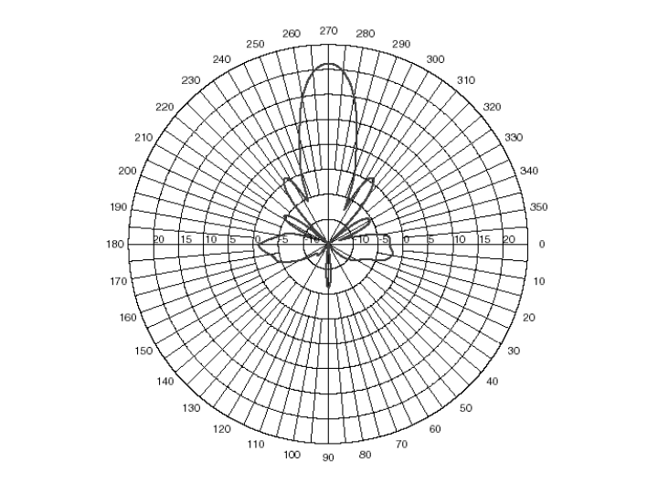
Figure 10-8: Antenna pattern.
The pattern shown in Figure 10-8 has 20 dB more gain in the forward direction
(270 degrees) than in any other direction. The side lobes occur at various
angles, but only two exceed the 0 dB circle on the graph (at 235 and 315
degrees). This antenna is said to have a “gain” of 20 dBi, that is, 20 dB relative
to an isotropic radiator.
This pattern also shows the Beamwidth of the antenna. This is usually stated as
the distance between the half-power points, or 3 dB points. From the graph, the
antenna beamwidth is 14 degrees.
Antennas also have vertical directionality, called elevation. It looks similar to
Figure 10-8.
10.7 Rain Fade
There are many causes for a radio signal to fade. The only one of concern here
is rain, and we will see that even that mechanism is negligible.
The concept is that if a certain amount of rain happens, then the RF is attenuated
by a few decibels, which reduces the Fade Margin of the link. If this happens a
percentage of the time, then one can predict the Outage of the link, hence
Availability.
ARCXtend manual, August 2003 10-9
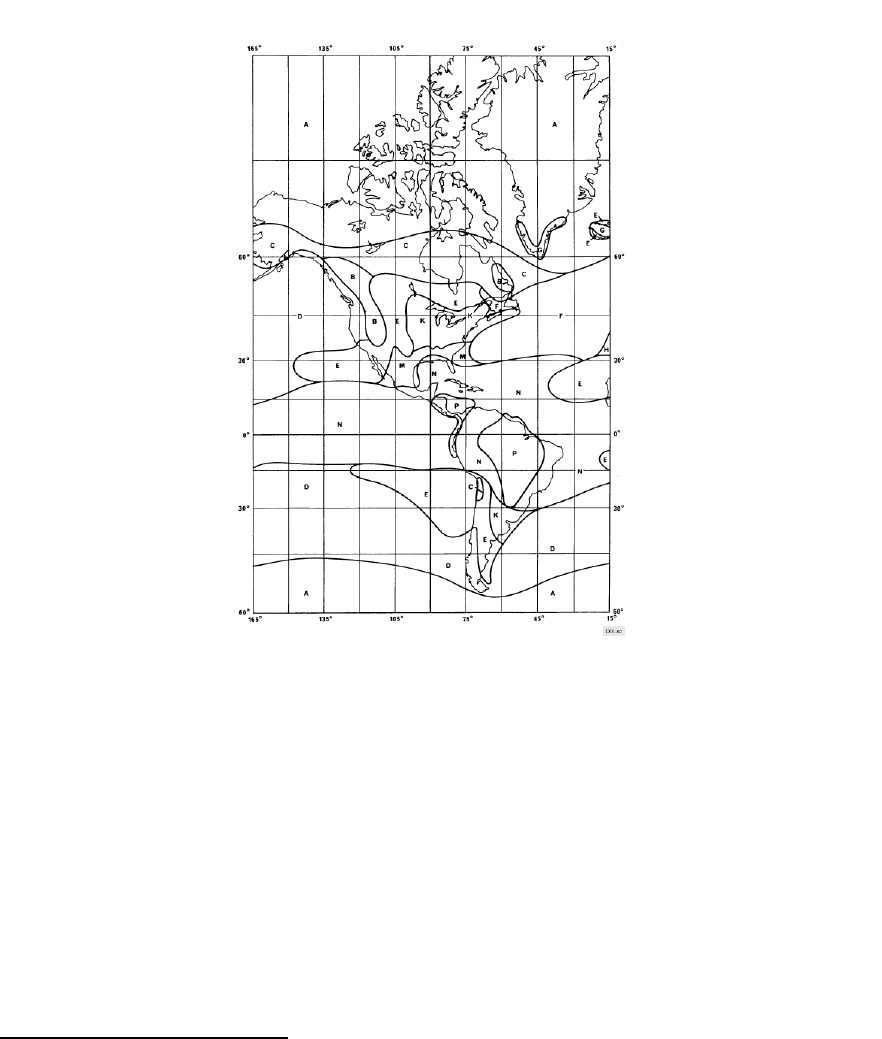
The world has been mapped into Rain Regions and historical data gathered on
the probability of rain at a given density (millimeters of rain per hour). The ITU
has created maps8 to help visualize this rain patterns, as in Figure 10-9.
In the United States, the 150 mm/hr rain rate happens only 0.001% of the time,
and that is in Florida (Region N). A percentage of 0.001% is approximately equal
to 5 minutes a year.
Figure 10-9: Rain Regions for the Americas (ITU-R P.837-1).
8 ITU-R P837-1. This older version of the standard uses alphabetical regions. The newer P837-2
maps by probability zones.
ARCXtend manual, August 2003 10-10
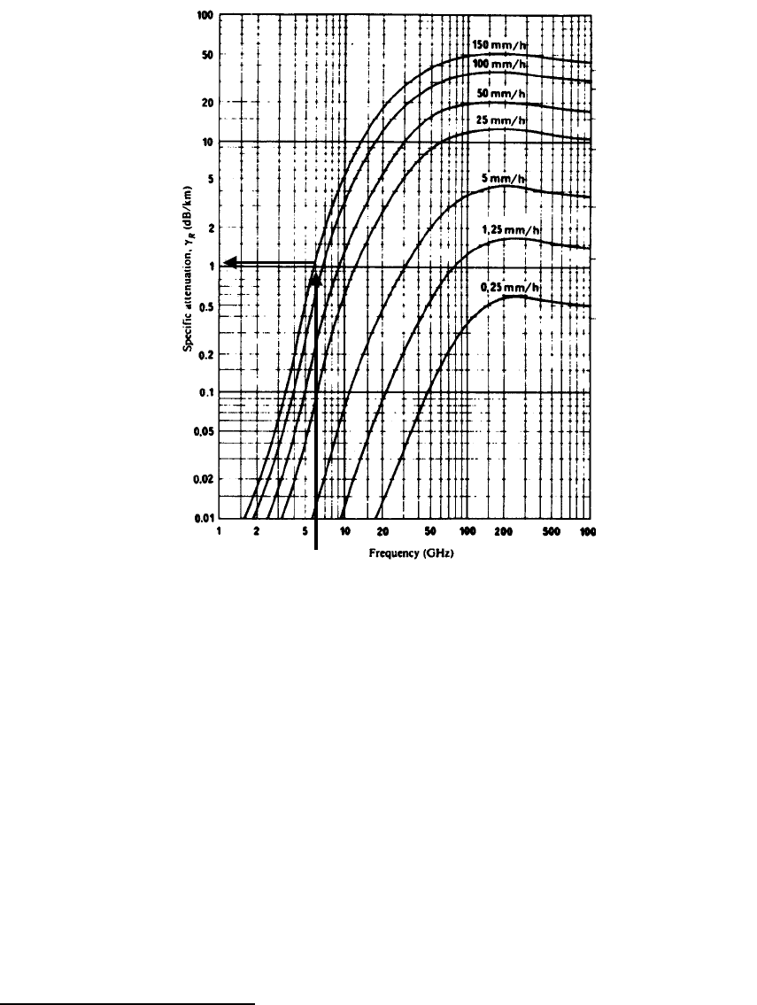
Figure 10-10: Rain Attenuation9 for 5 GHz band (ITU-R P.721-3).
Figure 10-10shows that the Rain Attenuation for the 5 GHz band is really about 1
dB at the very worst rain storm (150 mm/hr), which is a cloudburst, or worse. So
Rain Attenuation for this band is really small compared to cable losses, losses
due to connectors, etc.
10.8 Lightning Strikes
Obviously some regions have more frequent lightning strikes than others. One
map of the US is shown in Figure 10-11, also see IEEE 1410 Guide10.
9 ITU-R P.721-3 has been superceded by complex computer modeling, but this figure is still the
easiest to visualize the effects of rain.
10 IEEE P1410, Guide for Improving the Lightning Performance of Electric Power Overhead
Distribution Lines, draft 3, feb 2003.
ARCXtend manual, August 2003 10-11
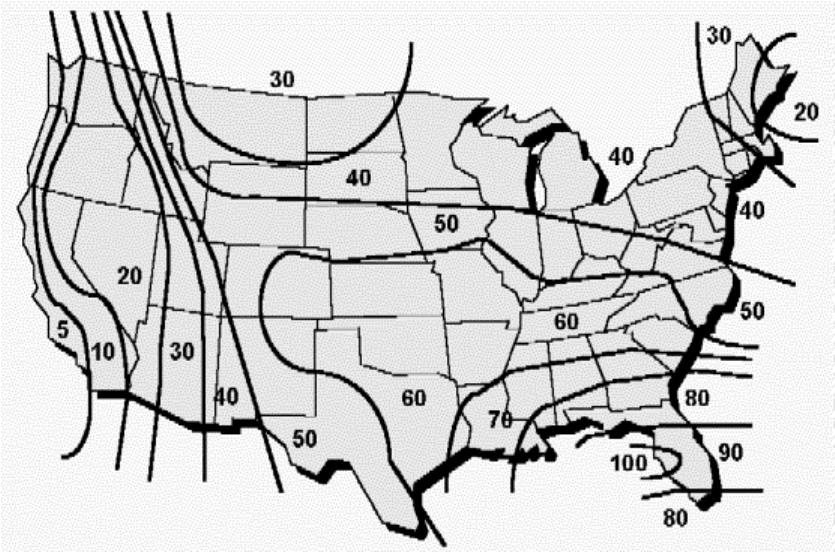
source: Larus Corp, “T1 Repeatered Line Transmission Engineering”, Issue 2,
1996.
Figure 10-11: Lightning strikes in the USA.
Although the frequency of lightning strikes varies across the USA, the same
lightning protection is used everywhere. The difference is that some carriers in
the regions with the most lightning schedule preventive maintenance to replace
protectors annually at the most exposed locations.
ARCXtend manual, August 2003 10-12
11 Reader Feedback
Readers of this Manual are encouraged to forward their corrections and
comments to:
Customer Service
Arcwave, Inc.
910 Campisi Way, #1C
Campbell, CA 95008 USA
408-558-2763 (direct)
techsupport@arcwaveinc.com
ARCXtend manual, August 2003 11-1