AsiaRF AWM002 WiFi AP Router Module User Manual
AsiaRF Ltd. WiFi AP Router Module Users Manual
UserManual.wiki
>
AsiaRF
>
AWM002 User Manual
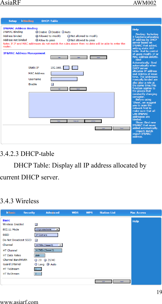
Users Manual
Navigation menu
Upload a User Manual
Namespaces
Wiki Guide
HTML
PDF
Info
Views
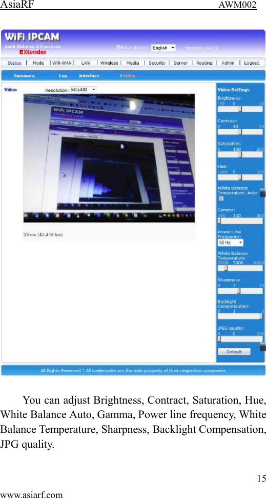
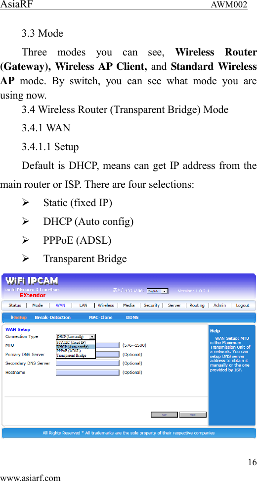
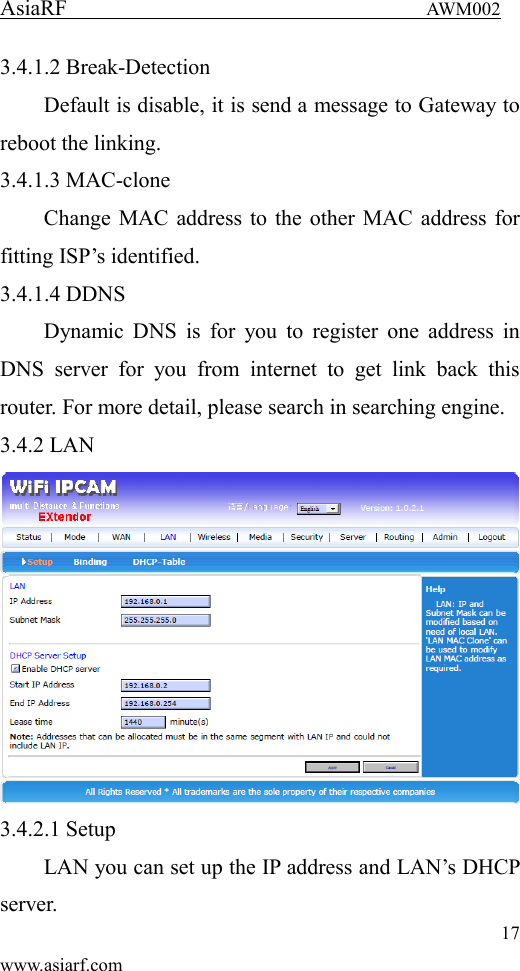
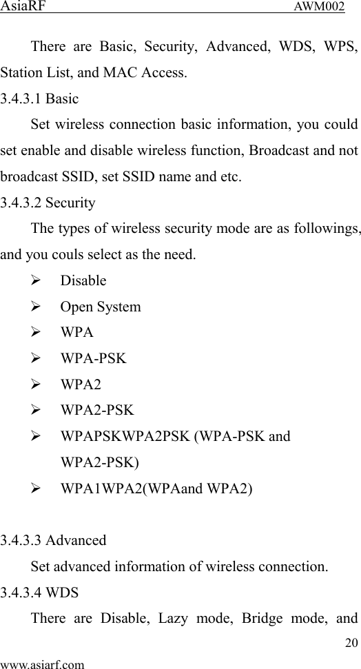
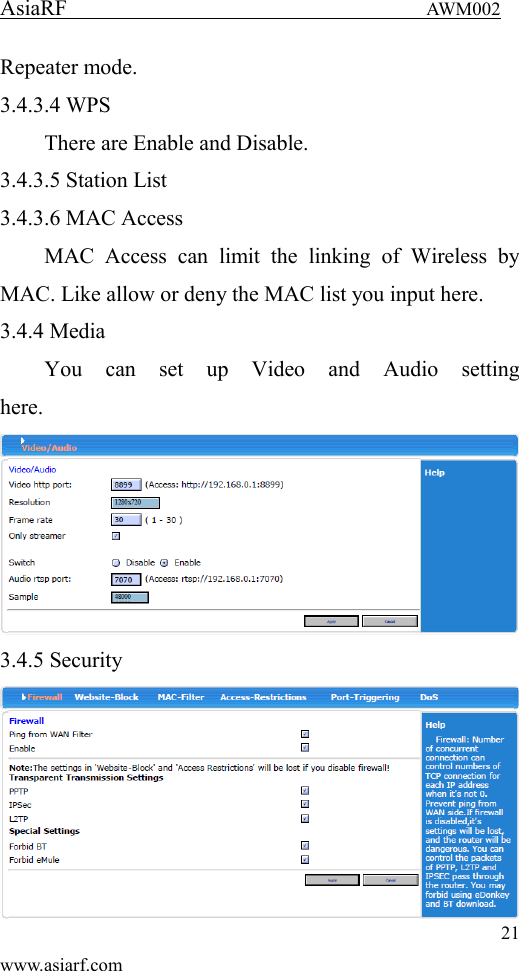
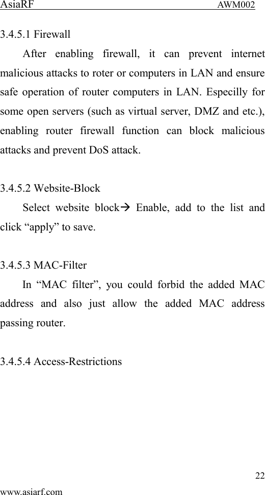
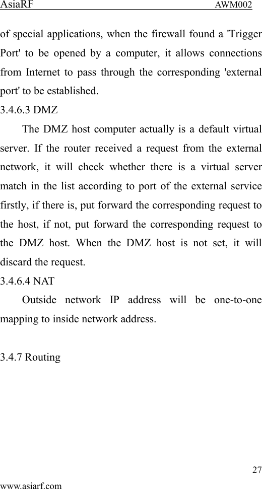
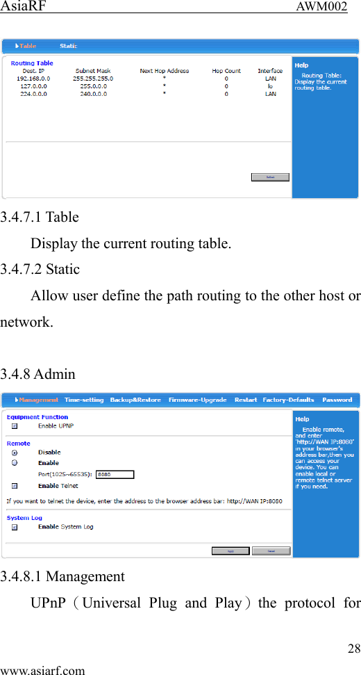
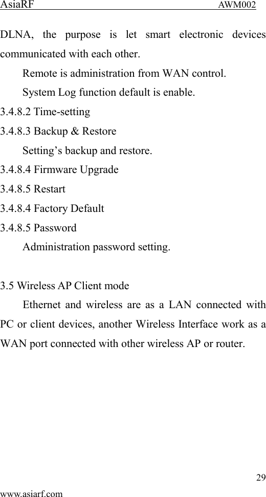
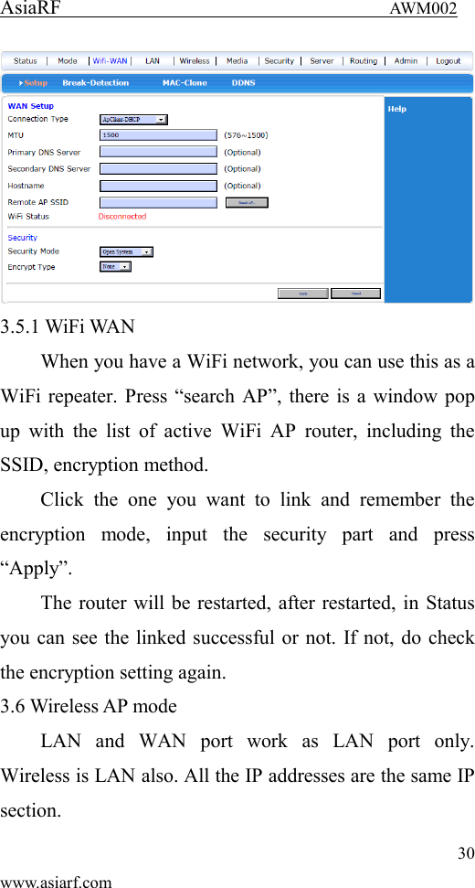
User Manual
Discussion / Help
Navigation