Asiatelco Technologies LM61 LTE Cat1 module User Manual LM61 20160513
Asiatelco Technologies Co. LTE Cat1 module LM61 20160513
User manual

LM61 User Manual
1
LM61UserManual

LM61 User Manual
2
Index
1.AboutthisManual............................................................................3
2.ProductOverview............................................................................3
3.Configuringthemodel....................................................................3
3.1Login ............................................................................................................... 3
3.2 Dashboard ...................................................................................................... 3
3.3 4G .................................................................................................................. 5
3.3.1Setting...............................................................................................................5
3.3.2APNSettings.....................................................................................................5
3.3.3PINManagement..............................................................................................5
3.3.4LANSettings......................................................................................................6
3.4 Status ............................................................................................................. 7
3.4.1WANStatus.......................................................................................................8
3.4.2LANStatus.........................................................................................................8
3.4.34GStatus...........................................................................................................8
3.4.4SoftwareStatus................................................................................................9
3.5 System ........................................................................................................... 9
3.5.1Password.........................................................................................................10
3.5.2Backup&Restore...........................................................................................10
LM61 User Manual
3
1. AboutthisManual
The content of this User Manual has been made as accurate as possible.
However, due to continual product improvements, specifications and other
informationaresubjecttochangewithoutnotice.
2. ProductOverview
LM61 supports LTE Band 4/13 (Subject to the configuration of LTE module)
anditsupportspopularoperatingsystemslikeWindows,LinuxandMac.
3. Configuringthemodel
The basic settings in WebGUI consist of four main parts named
Dashboard,4G,Status and System. You can login to WebGUI as follows, and
configurethesettingsaccordingtoyourrequirements.
Connect the PC to LM61 with DB100, waiting for about one minuteuntilthe
devicefinishedinitializing.PleaseensurethatUSIM cardhas beeninsertedinto
USIMslot.
3.1Login
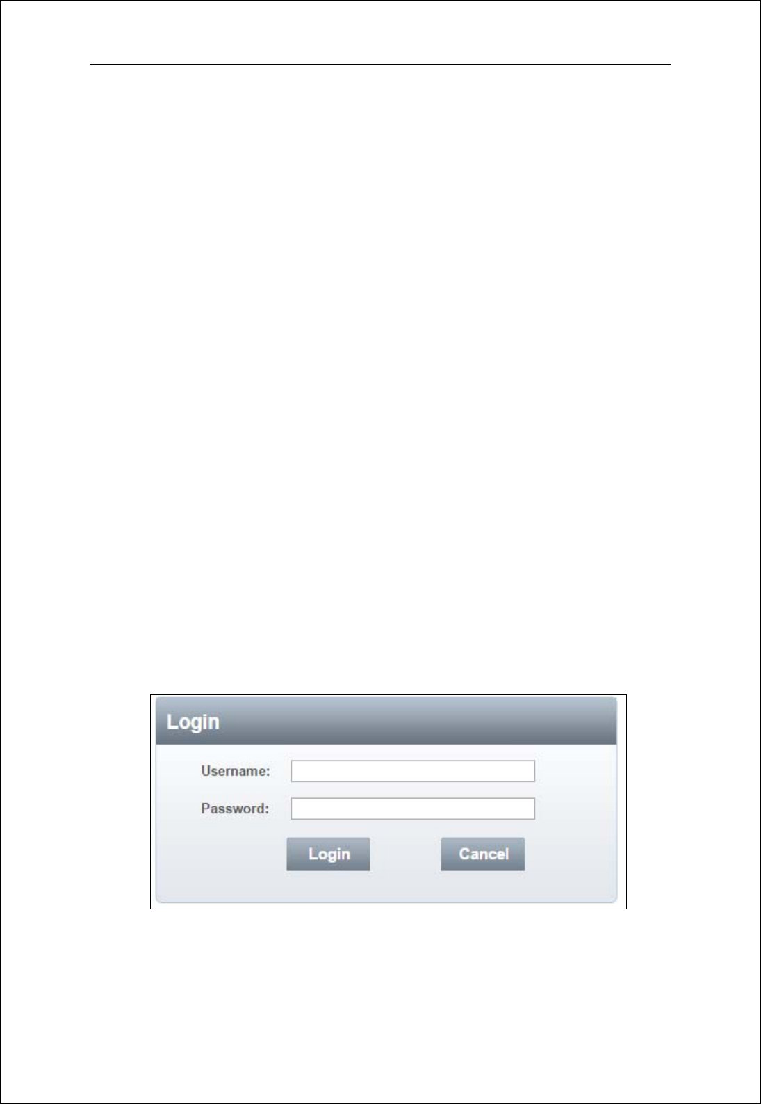
OpenyourWebbrowserandenter10.0.0.1intheaddressbar;
Loginwindowwillpopup;
When prompted for User name and password, enter the following username
andpassword.
Username/Password:admin/admin
3.2 Dashboard
Aftersuccessfullogin,thefollowingscreenwillappearandyou will see six
menusonthetopbaroftheWebGUI.
LM61 User Manual
4
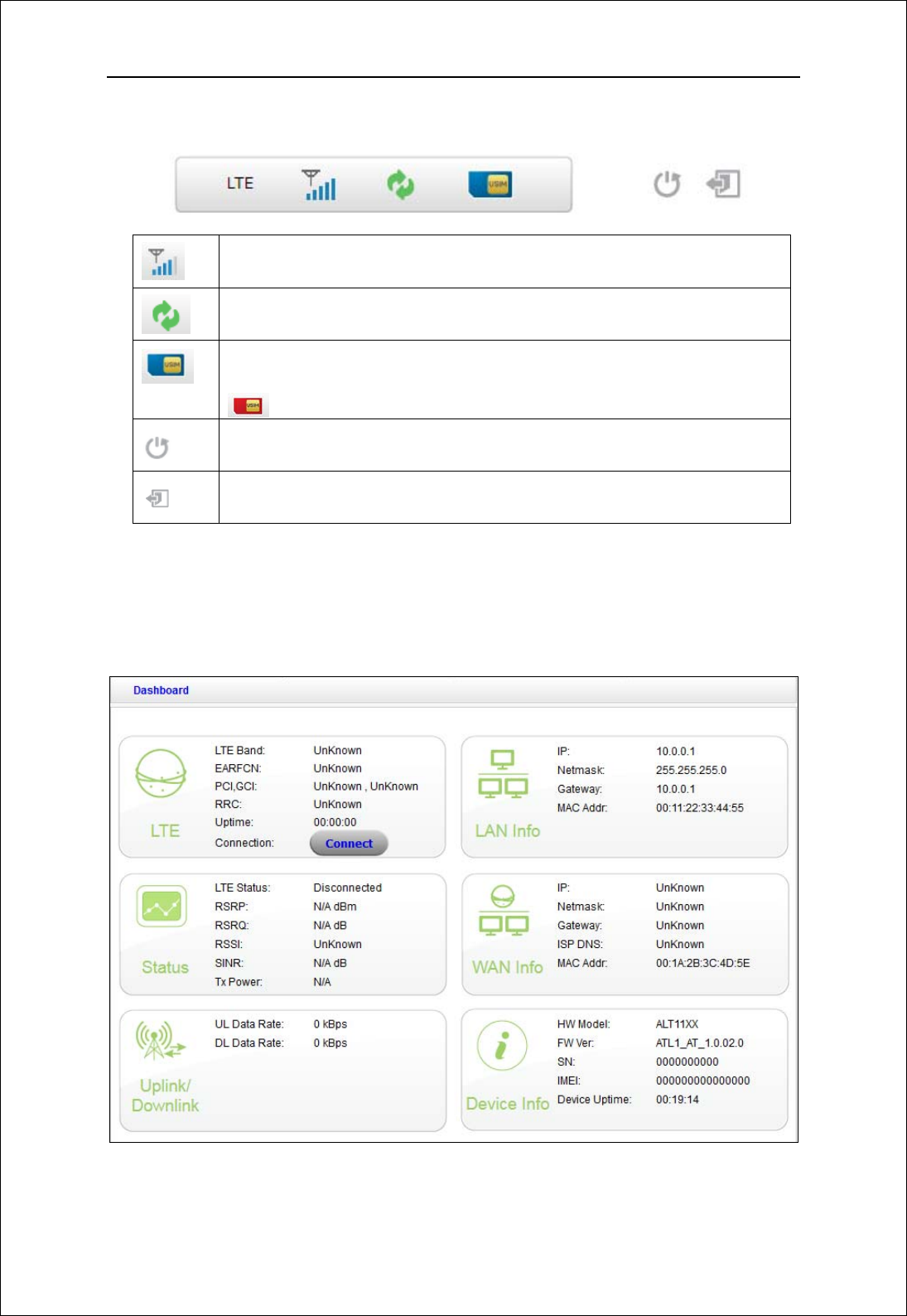
The bars in the middle indicate the received signal level, data connection
status,USIMstatusshownasbelowpicture:
LTEsignallevel
DataconnectionIcon,whenmodelconnecttonetwork,theicon
ison,otherwise,itisgrey
USIMcardstatus.
IfmodelworkwithoutUSIMcard.TheUSIMcardiconchangeto
Rebootkey.Itisusedtorebootthedevice
Logoutkey.ItisusedtologoutWebpage
Figure 3-2-1 Icon
Fromdashboardpage,youcanalsoknow4Gstatus,status,WANInfo,LANInfo,
uplink/downlink and Device Info. You can see the dashboard pageasfigure
3‐2‐2.
Figure 3-2-2 Dashboard Page
LM61 User Manual
5
3.3 4G
3.3.1 Setting
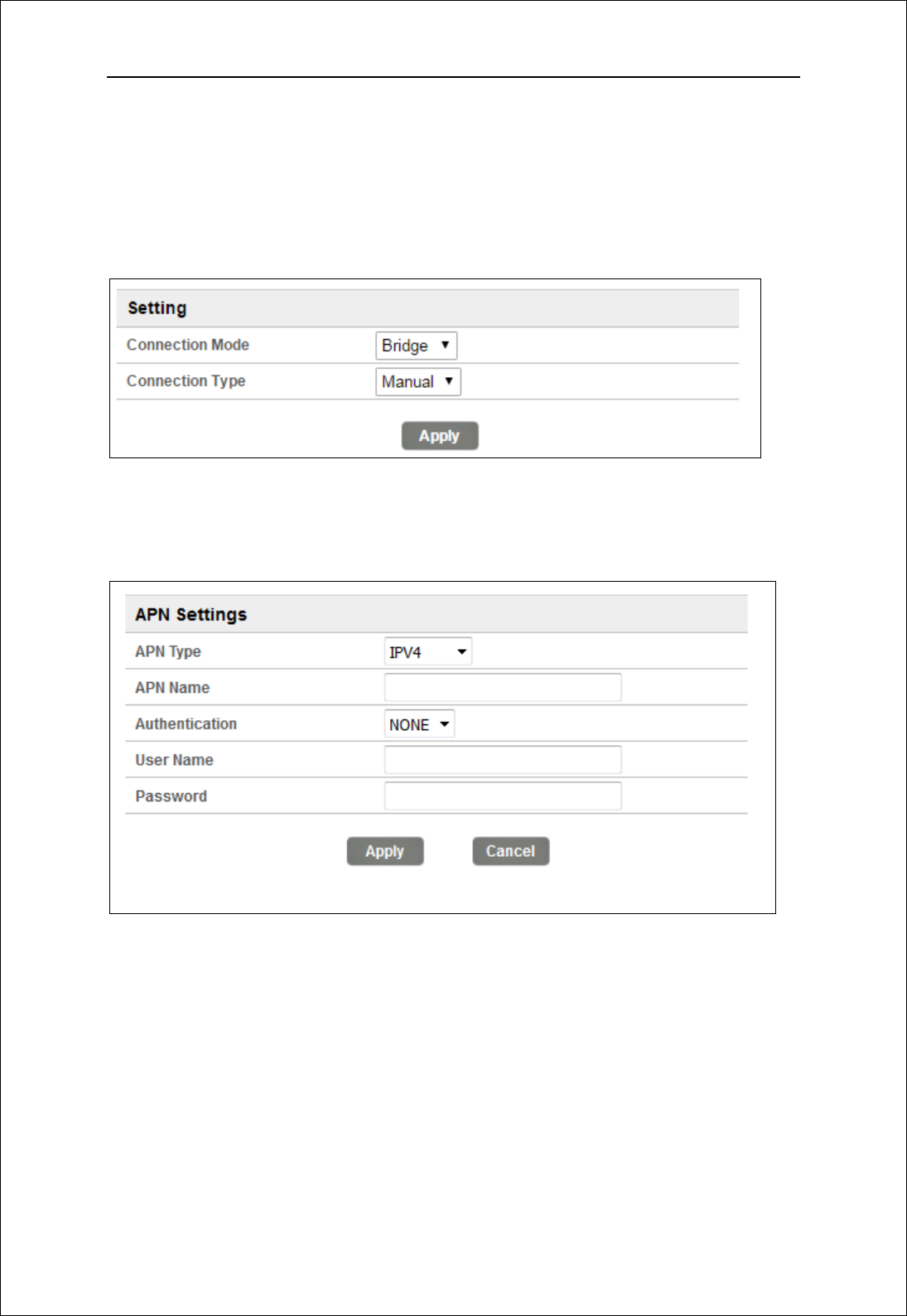
Connection Mode: bridge and router, default mode is bridge
Connection Type: Auto and manual, default type is auto
Figure 3-3-1-1 Setting
3.3.2 APN Settings
Figure 3-3-2-1 APN Settings
ThedefaultAPNtypeisIPV4andAPNisNULL,ifyouwanttoconfiguretheLTE
APN,youshouldchoosethemanualmode,andthenyoucanconfigurethe APN
settings
3.3.3 PIN Management
Fromthispage,youcanseetheUSIMcardstatusandPINstatus.
LM61 User Manual
6
Figure 3-3-3-1 PIN Management
ThedefaultPINstatusisdisabled;youcaninputthecorrectPINtoenablethe
PINfunction.ThemaximumPINattemptsare3;otherwiseyoumustenterPUKto
resetthePINcode.TheUSIMwillbeinvalidaftertheunsuccessfulattemptsfor10
times.
PINManagement:Enter the correct PIN to enable or disable the PIN
function,PINcodeshouldbe4to8digits;
3.3.4 LAN Settings
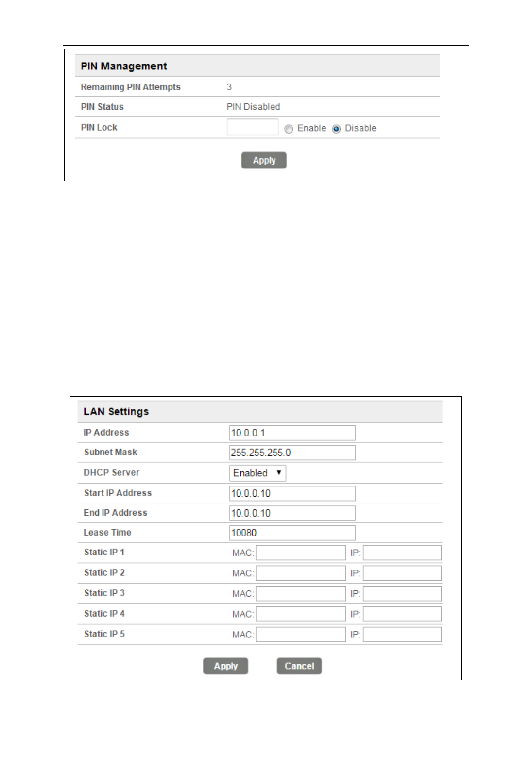
Fromthispage,youcansetallsettingsfortheinternalLAN.
Figure 3-3-4-1 LAN Settings
LM61 User Manual
7
IPAddressEntertheIPaddressofyourrouter(factorydefault:
192.168.0.1).
SubnetMask‐Anaddresscodethatdeterminesthesizeofthenetwork.
Normallyuse255.255.255.0asthesubnetmask.
DHCP‐EnableorDisabletheDHCPserver.IfyoudisabletheServer,Client
cannotgetvalidIPaddressfrommodelautomatically.Butyoucanconfigure
theaddressofyourPCmanuallytoconnectmodel
StartIPAddress‐SpecifyanIPaddressfortheDHCPservertostartwith
whenassigningIPaddress.Thedefaultstartaddressis10.0.0.10.
EndIPAddress‐SpecifyanIPaddressfortheDHCPServertoendwith
whenassigningIPaddress.Thedefaultendaddressis10.0.0.10.
LeaseTime‐TheLeaseTimeistheamountoftimeanetworkuserwillbe
allowedconnectiontotherouterwiththeircurrentdynamicIPaddress.
Entertheamountoftimeinminutesandtheuserwillbe"leased"this
dynamicIPaddress.Afterthetimeisup,theuserwillbeassignedanew
dynamicIPaddressautomatically.
StaticIP‐IP/MACbindingfunction,thesystemwillassignafixedIPaddress
totheMACaccordingtotherules.
Note:
1. IfyouchangetheIPAddressofLAN,youmustusethenewIPaddresstologin
totheMODELrouter.
2. IfthenewLANIPaddressyousetisnotinthesamesubnet,theIPaddress
pooloftheDHCPserverwillchangeatthesametime,whiletheVirtualServer
andDMZHostwillnottakeeffectuntiltheyarere‐configured.
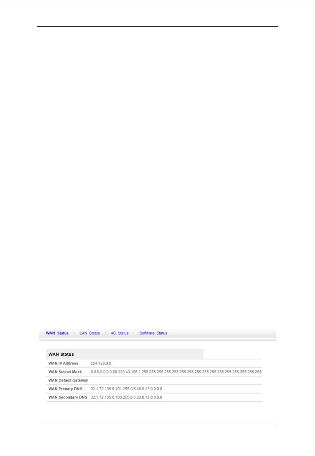
3.4 Status
Onthispage,youcanseeWANStatus,LANStatus,4GStatusandSoftwareStatus.
LM61 User Manual
8
Figure 3-4-1 Status
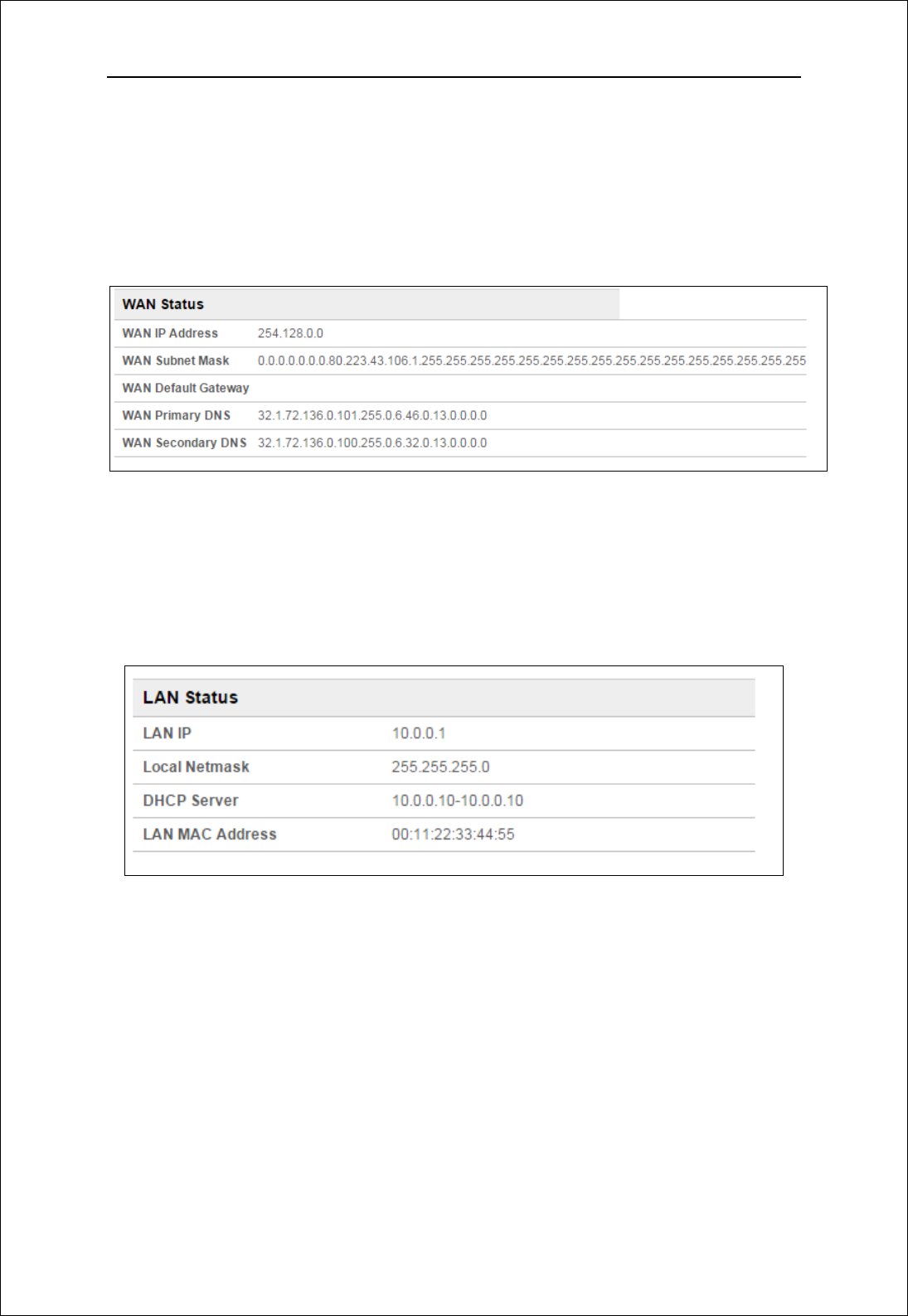
3.4.1 WAN Status
FromtheWANStatus,WANIPAddress,WANPrimaryDNSandWANSecondary
DNSinformationcanbedisplayed
Figure 3-4-1-1 WAN Status
3.4.2 LAN Status
Fromthispage,youcanseetheLANStatussuchasIP,localnetmask,DHCPserver
andMACaddress.
Figure 3-4-2-1 WiFi LAN Status
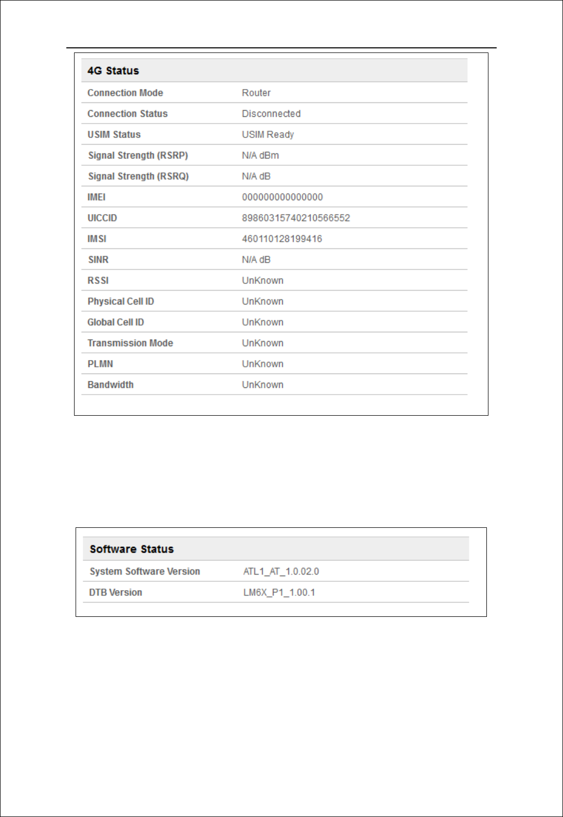
3.4.3 4G Status
Clickingonthe“4GStatus”,youcanseetheLTEinformationsuchasConnection
Status,USIMStatus,IMEI,IMSI,RSSI,andSINR.
LM61 User Manual
9
Figure 3-4-3-1 LTE Status
3.4.4 Software Status
SoftwareversionandtheDTBversioncanbedisplayed.
Figure 3-4-4-1 Software
3.5 System
On this page you can set System Menu: Password and backup & restore.
LM61 User Manual
10
Figure 3-5-1 System
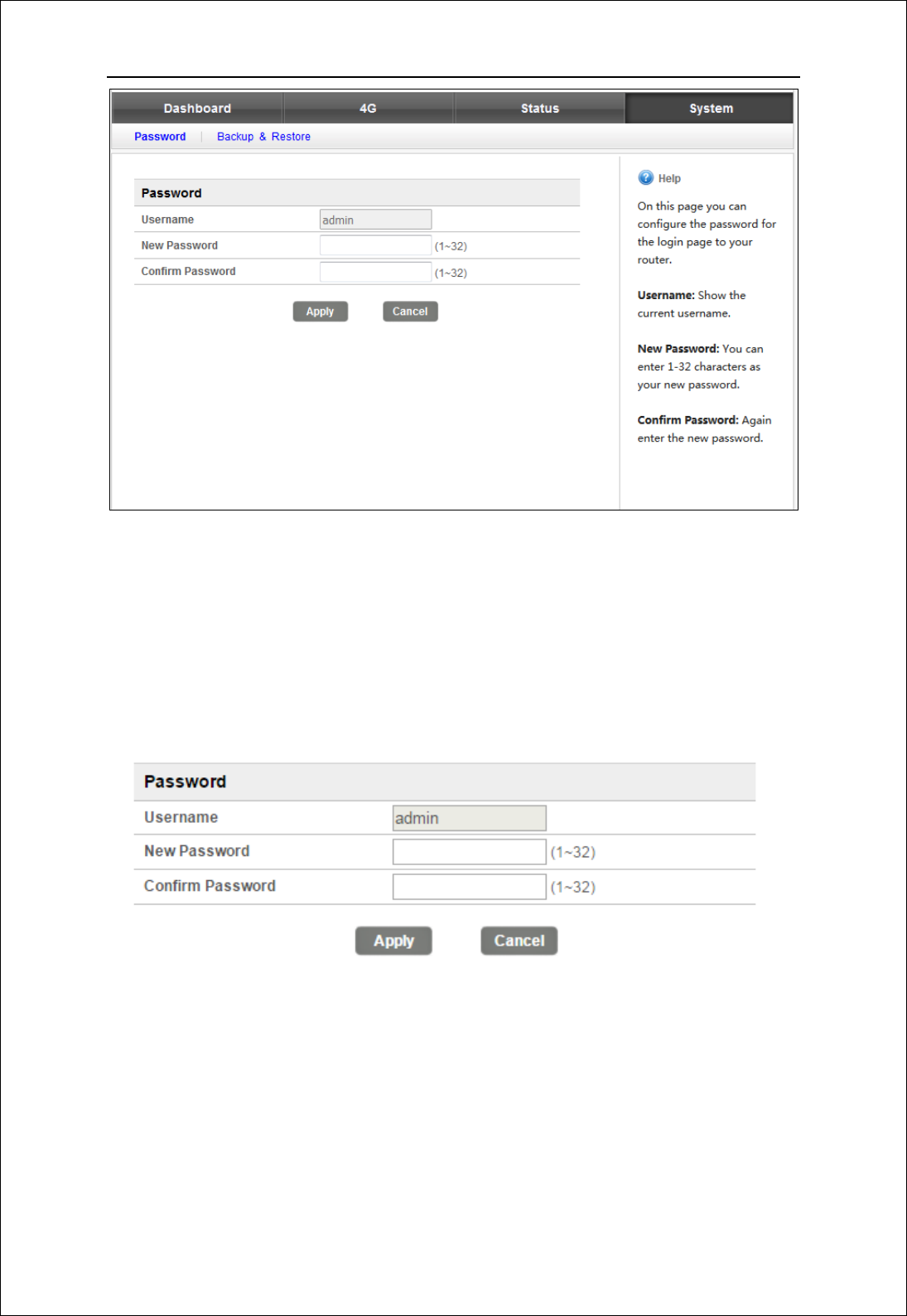
3.5.1 Password
Thedefaultpasswordisadmin,youcanenter1~32charactersfor2timesas
yournewpassword.Thenyouwouldlogoutautomaticallyandyoushouldloginto
thesystembythenewpassword.
Figure 3-5-1-1 Password
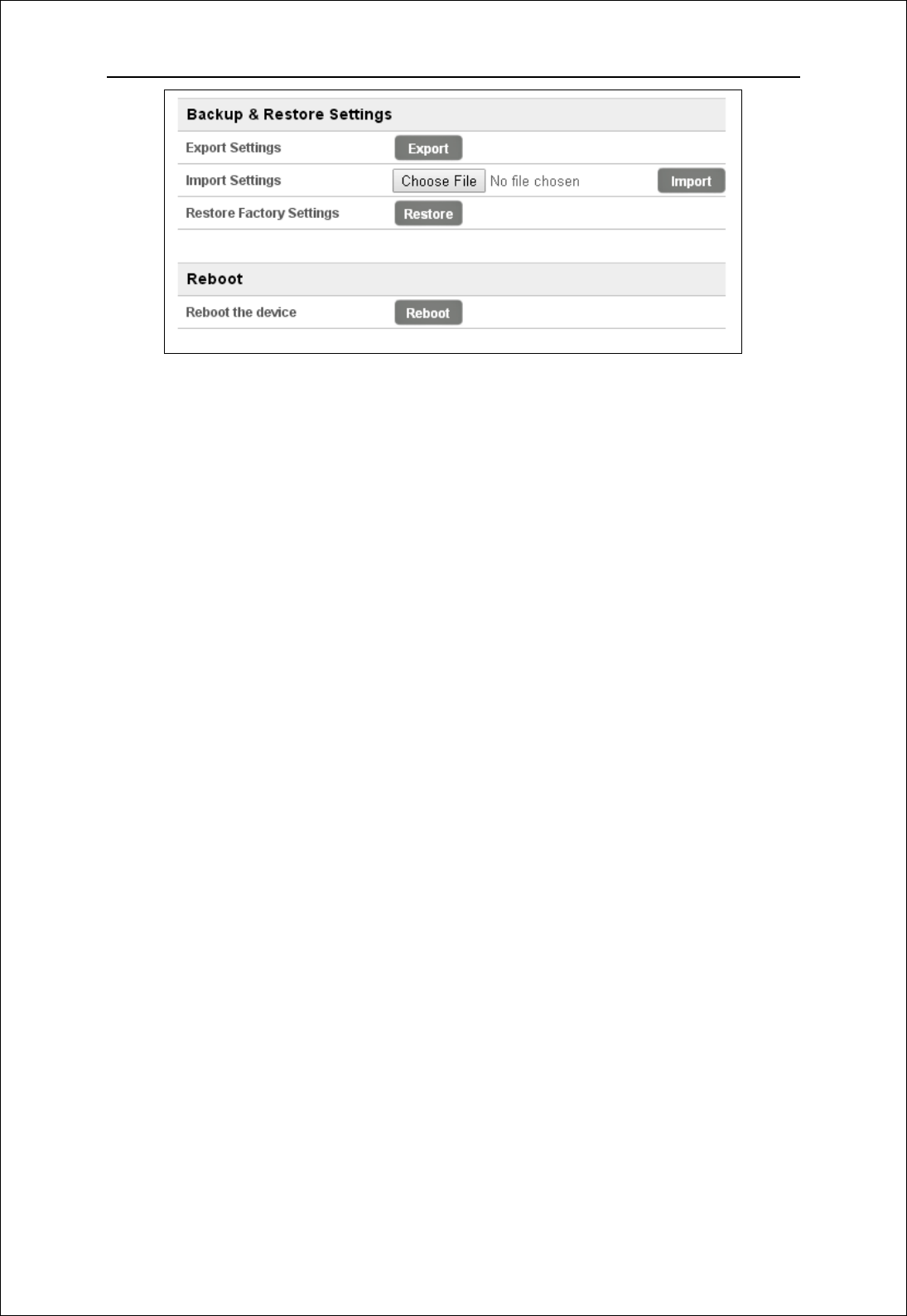
3.5.2 Backup & Restore
Clickingthe“Export”button,thecurrentsettingswillbesavedasadatafileto
thelocalPC.Youcanimportthedeviceconfigurationfromthefilesthatyousaved.
Youcanrestoreandrebootthedevice.
LM61 User Manual
11
Figure 3-5-2-1 Backup & Restore
Federal Communications Commission (FCC) Statement
15.21
You are cautioned that changes or modifications not expressly approved by the part
responsible for compliance could void the user’s authority to operate the equipment.
15.105(b)
This equipment has been tested and found to comply with the limits for a Class B digital
device, pursuant to part 15 of the FCC rules. These limits are designed to provide
reasonable protection against harmful interference in a residential installation. This
equipment generates, uses and can radiate radio frequency energy and, if not installed
and used in accordance with the instructions, may cause harmful interference to radio
communications. However, there is no guarantee that interference will not occur in a
particular installation. If this equipment does cause harmful interference to radio or
television reception, which can be determined by turning the equipment off and on, the
user is encouraged to try to correct the interference by one or more of the following
measures:
-Reorient or relocate the receiving antenna.
-Increase the separation between the equipment and receiver.
-Connect the equipment into an outlet on a circuit different from that to which
the receiver is connected.
-Consult the dealer or an experienced radio/TV technician for help.
This device complies with Part 15 of the FCC Rules. Operation is subject to the
following two conditions:
1) this device may not cause harmful interference and
2) this device must accept any interference received, including interference that may
cause undesired operation of the device.

LM61 User Manual
12
FCC RF Radiation Exposure Statement:
To comply with the FCC RF exposure compliance requirements, this device and its
antenna must not be co-located or operating in conjunction with any other antenna or
transmitter. This equipment should be installed and operated with a minimum distance of
20 centimeters between the radiator and your body.
End Product Labeling:
This module is designed to comply with the FCC statement, FCC ID :XYOLM61
The host system using this module, should have label in a visible area indicated the
following texts:
"Contains FCC ID : XYOLM61 ".
Manual Information to the End User
The OEM integrator has to be aware not to provide information to the end user regarding
how to install or remove this RF module in the user’s manual of the end product which
integrates this module.
The end user manual shall include all required regulatory information/warning as shown in
this manual.
Antenna Restriction
For mobile and fixed operating configurations the antenna gain, including cable loss, the
device, module LM61 must not exceed the following gain values per bands
for B4 1710-1755 MHz, 1.34 dBi gain
for B13 777-787 MHz , 20.75 dBi gain