Asis Technologies R380 Reader User Manual R380 Reader x
Asis Technologies Pte Ltd Reader R380 Reader x
UserManual.wiki
>
Asis Technologies
>
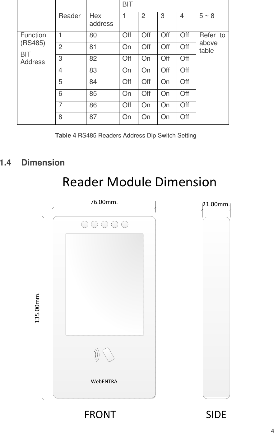
R380 User Manual
Users Manual
Navigation menu
Upload a User Manual
Namespaces
Wiki Guide
HTML
PDF
Info
Views
User Manual
Discussion / Help
Navigation
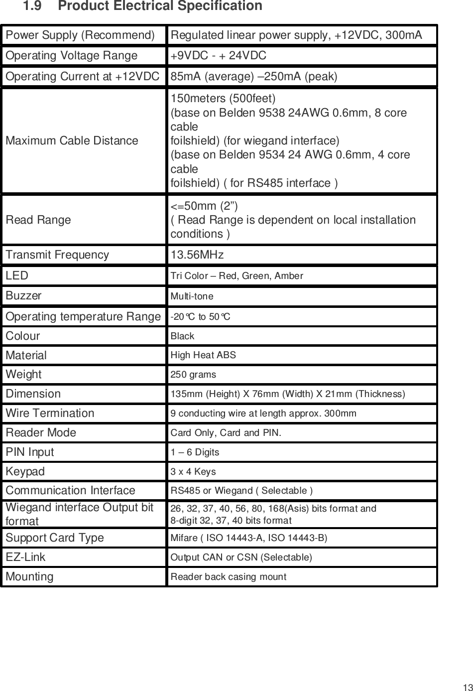
![12 1.8 Package List – R380 Reader Item Description: Complete with snap on cover. 1 x Mounting cover security screw [M3], 1 x security screw driver, and this document. Radio Frequency Interference Devices generate RF noise that may interfere with the reception of the signal from the access card. This will result in the reduction of read range. Examples of devices are radios, televisions, and cellular phones. The read range is affected by the amount of interference (noise) in the area. The reader should mount more than 1.5m away from the any devices that emits RF that may interfere with the signal received from the access control cards.](https://usermanual.wiki/Asis-Technologies/R380/User-Guide-3628594-Page-12.png)