Askey Computer RAC2V1K DBDC ROUTER User Manual Spectrum WiFi User Manual draft ok
Askey Computer Corp DBDC ROUTER Spectrum WiFi User Manual draft ok
UserManual.wiki
>
Askey Computer
>
RAC2V1K User Manual
User Manual
Navigation menu
Upload a User Manual
Namespaces
Wiki Guide
HTML
PDF
Info
Views
User Manual
Discussion / Help
Navigation

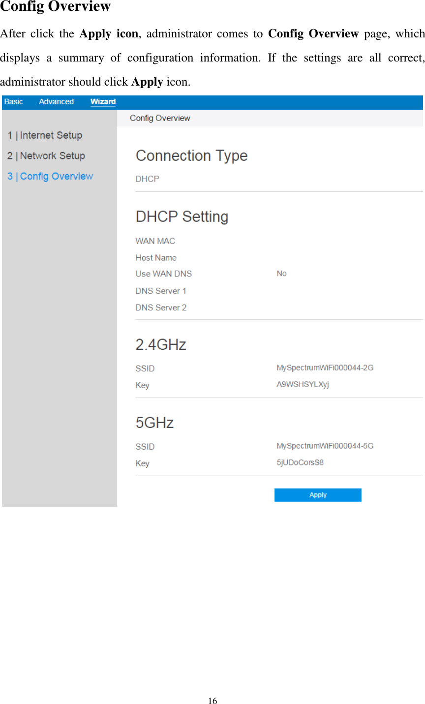
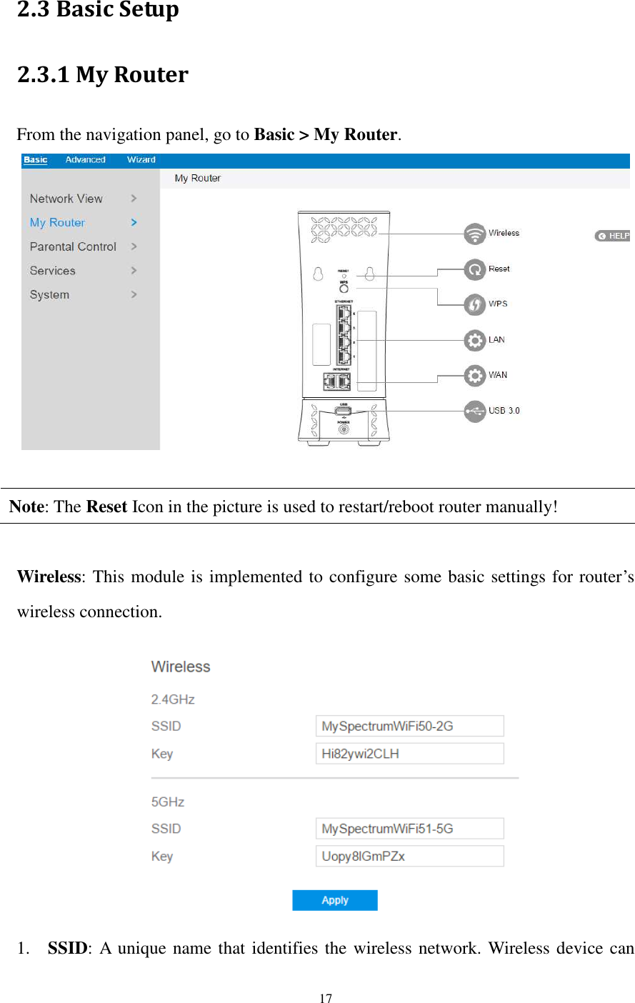
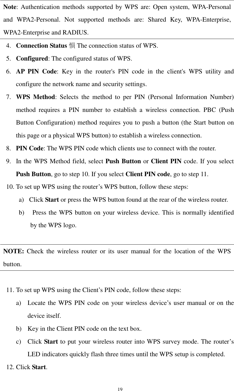
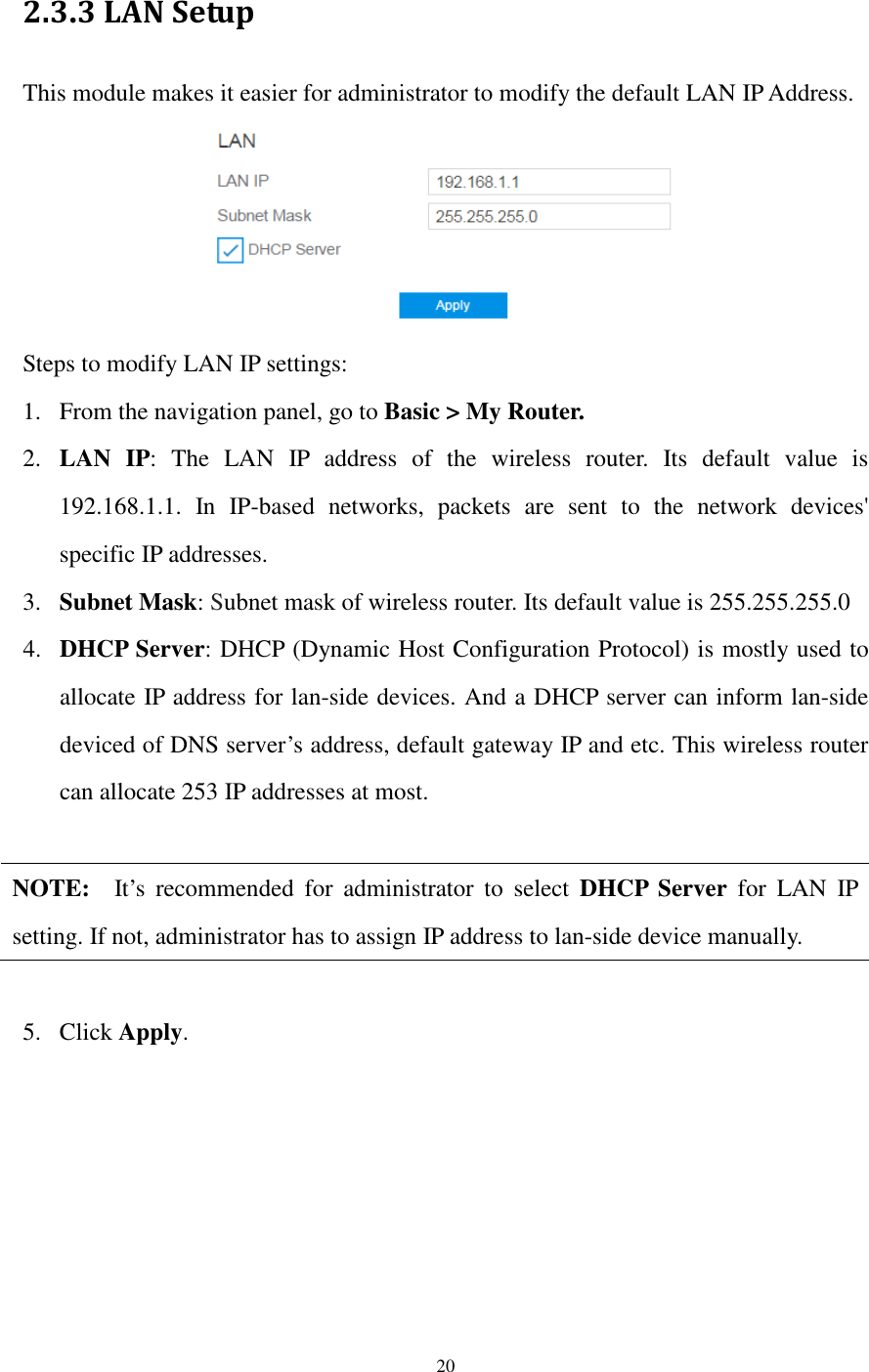
![18 automatically detect all networks within its communication range. The maximum length of a SSID is 32 characters. 2. Key: A string used for connection authentication. Its length ranges from 0 to 63 characters(letters, numbers or a combination) or from 8 to 64 hex digits. 3. Click Apply. 2.3.2 WPS Setup WPS (Wi-Fi Protected Setup) is a wireless security standard that allows the device easily connect to a wireless network. You can configure the WPS function via the PIN code or WPS button. Steps to enable WPS(Wi-Fi Protected Setup): 1. From the navigation panel, go to Basic > My Router. 2. Frequency: Selecting operating band (2.4 GHz or 5 GHz) for WPS function. Note: If WPS has been enabled and administrator intends to change the frequency, please disable WPS first. 3. Enable WPS: Selecting [On] to run WPS, witch simplifies the process of connecting any device to the wireless network](https://usermanual.wiki/Askey-Computer/RAC2V1K/User-Guide-3305952-Page-19.png)
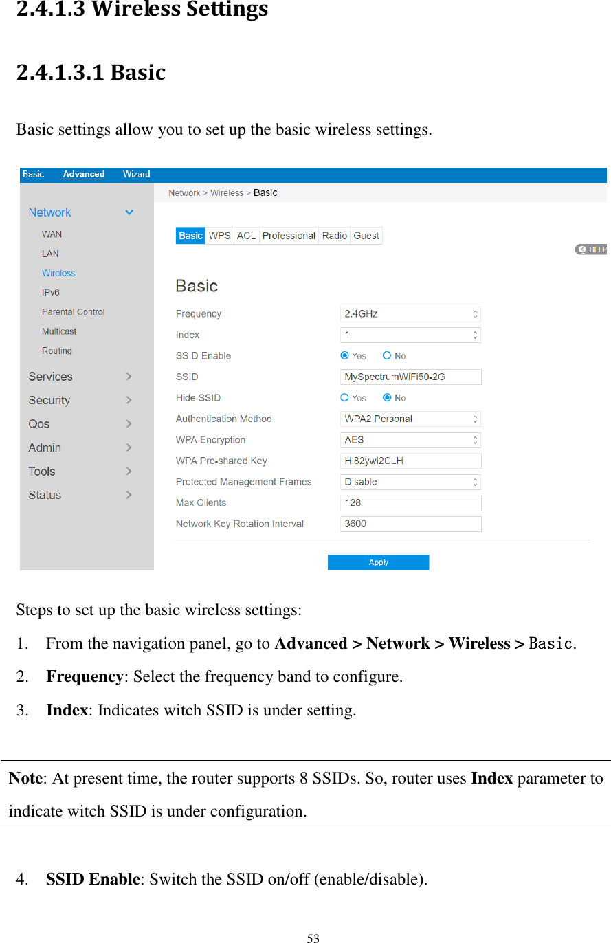
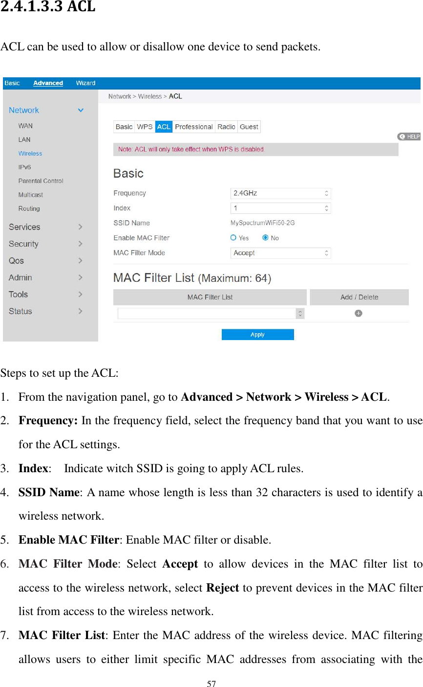
![54 5. SSID: A name whose length is less than 32 characters is used to identify a wireless network. WiFi devices automatically detect all networks within its communication range. 6. Hide SSID: If [Yes] is selected, SSID does not show in site surveys by wireless mobile clients and they can only connect to wireless router by manually entering SSID. 7. Authentication Method: This field enables authentication methods for wireless clients. 8. WPA Encryption: Enable WPA Encryption to encrypt data. 9. WPA Pre-Shared Key: Requires a password of 8-63 characters (letters, numbers or a combination) or 8 - 64 hex digits to start the encryption process. 10. Protected Management Frames: Protected Management Frames is a feature to protect some types of management frames like deauthorization, disassociation and action frames. 11. Max Clients: The maximum number of clients allowed. 12. Network Key Rotation Interval: This field specifies the interval (in seconds) after which a WPA group key is changed. Enter [0] (zero) to indicate that a periodic key-change is not required. Please input the value between 600 to 86400 (seconds). 13. Click Apply.](https://usermanual.wiki/Askey-Computer/RAC2V1K/User-Guide-3305952-Page-55.png)
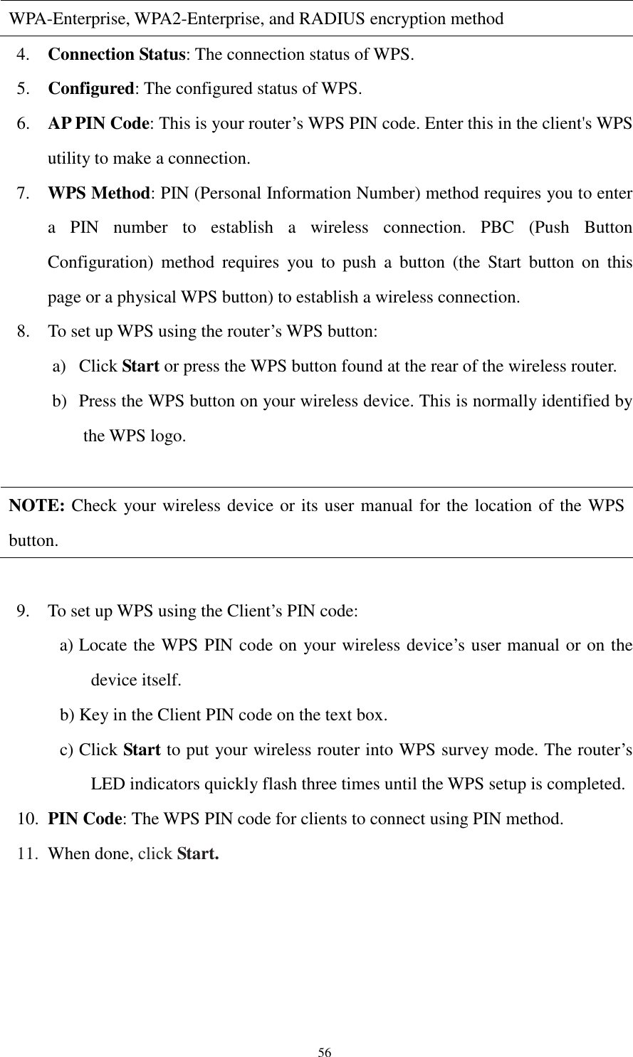
![55 2.4.1.3.2 WPS WPS (Wi-Fi Protected Setup) is a wireless security standard that allows you to easily connect devices to a wireless network. You can configure the WPS function via the PIN code or WPS button. WPS supports the authentication of Open system, WPA-Personal and WPA2-Personal. Not supported: Shared Key, WPA-Enterprise, WPA2-Enterprise and RADIUS. Steps to set WPS: 1. From the navigation panel, go to Advanced > Network > Wireless > WPS. 2. Frequency: Select an operating band (2.4 GHz or 5 GHz) for WPS. To change the operating band, please disable the WPS function first. 3. Enable WPS: Selecting [On] to enable WPS. This can simplify the process of connecting any device to the wireless network. NOTE: WPS supports authentication using Open System, WPA-Personal, and WPA2 - Personal. WPS does not support a wireless network that uses a Shared Key,](https://usermanual.wiki/Askey-Computer/RAC2V1K/User-Guide-3305952-Page-56.png)
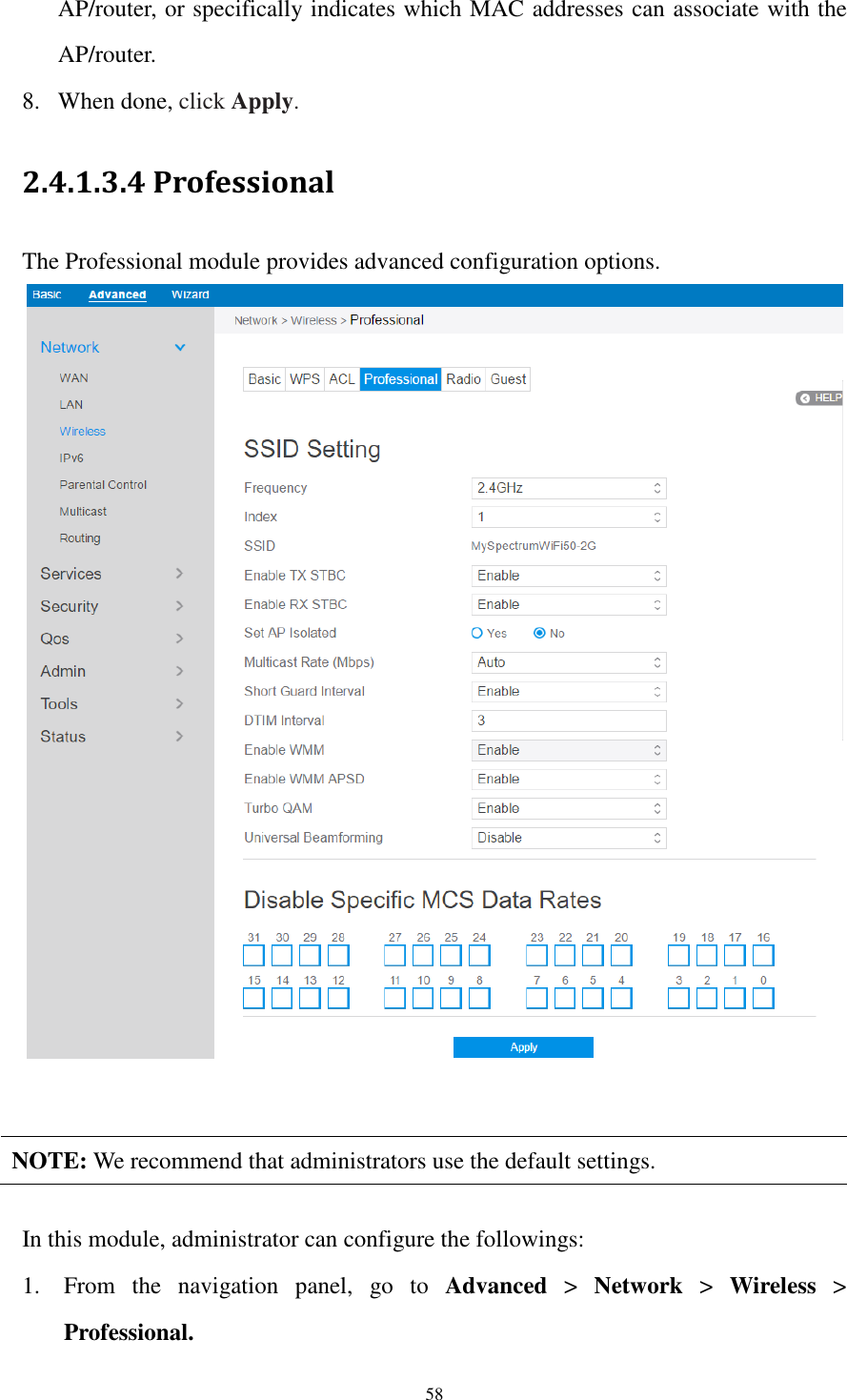
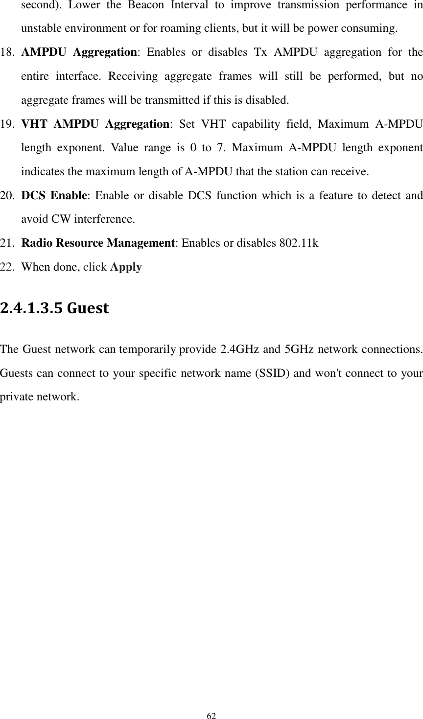
![59 2. Frequency: Select the frequency band to configure professional settings. 3. Index: Indicates witch SSID is under setting. 4. SSID: A name whose length is less than 32 characters is used to identify a wireless network. 5. Enable TX STBC: Enables or disables the Space Time Coding Block (STBC) feature, as described in 802.11n specification, in transmitting (TX) direction. 6. Enable RX STBC: Enables or disables the Space Time Coding Block (STBC) feature, as described in 802.11n specification, in receiving(RX) direction. 7. Set AP Isolated: Prevent wireless devices from communicating with each other via router. This feature is useful if many guests frequently join or leave your network. Select [Yes] to enable this feature or select [No] to disable. 8. Multicast Rate (Mbps): Setting transmission rate for multicast. 9. Short Guard Interval: Defines the length of time that the router spends for CRC (Cyclic Redundancy Check). CRC is a method of detecting errors during data transmission. Select Enable for a busy wireless network with high network traffic. 10. DTIM Interval: DTIM (Delivery Traffic Indication Message) Interval or Data Beacon Rate is the time interval before a signal is sent to a wireless device in sleep mode indicating that a data packet is awaiting delivery. The default value is three milliseconds. 11. Enable WMM: Enables or disables WMM capabilities in the driver. The WMM capabilities perform special processing for multimedia stream data including voice and video data. 12. Enable WMM APSD: Enable WMM APSD (Wi-Fi Multimedia Automatic Power Save Delivery) to improve power management between wireless devices. Select Disable to switch off WMM APSD. 13. Turbo QAM: 256-QAM (MCS 8/9) support. Wireless Mode must be set to auto. 14. Universal Beamforming: For legacy wireless network adapters which do not support beamforming, the router estimates the channel and determines the steering direction to improve the downlink speed. (Also known as Implicit](https://usermanual.wiki/Askey-Computer/RAC2V1K/User-Guide-3305952-Page-60.png)
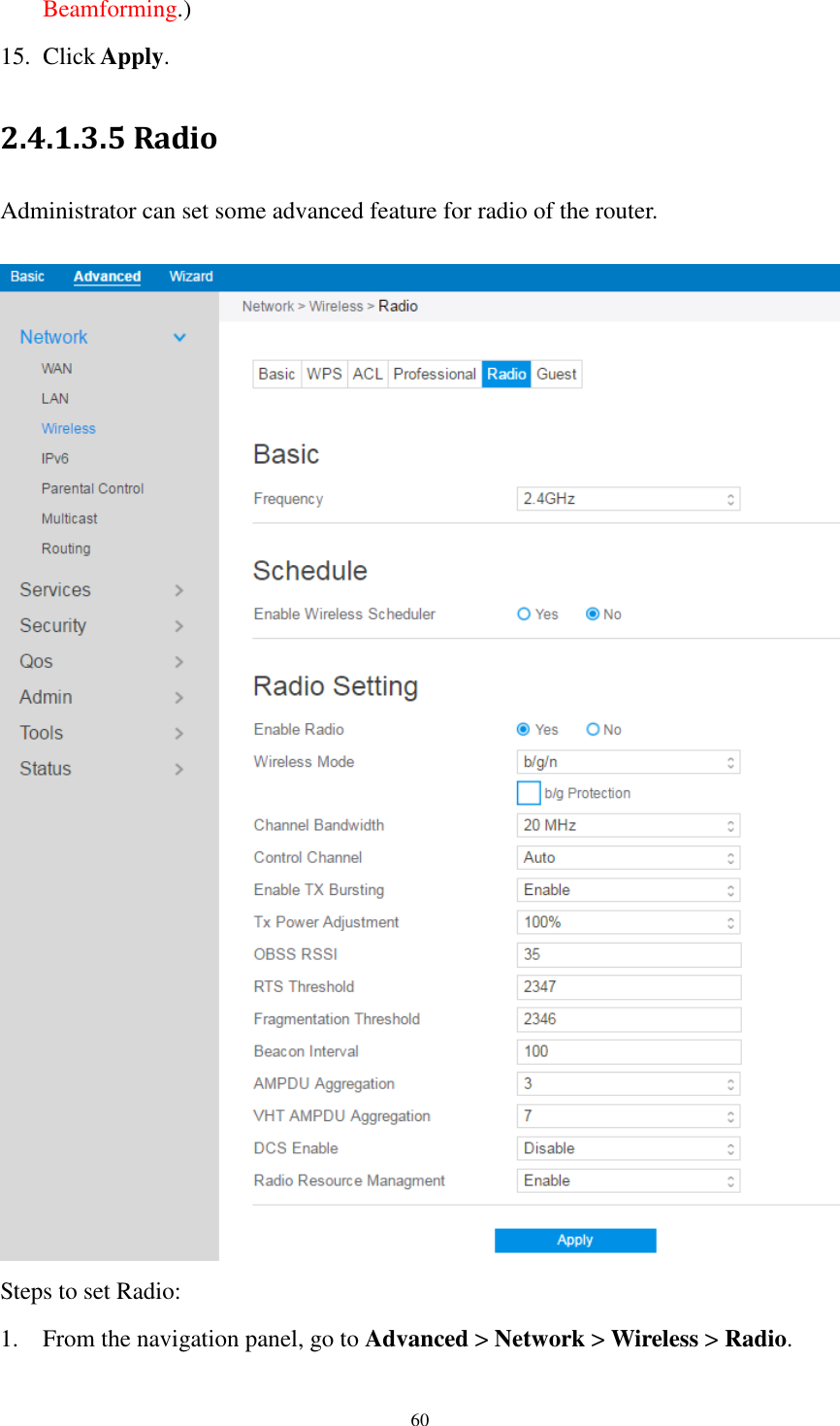
![61 2. Frequency: Selecting the frequency band that the router is running. 3. Enable Wireless Scheduler: Switch wireless schedule on or not. 4. Date to Enable (Weekdays): Select weekdays to enable Wi-Fi. 5. Time of Day To Enable: Set weekday time to enable Wi-Fi. 6. Date to Enable (Weekend): Select weekend days to enable Wi-Fi. 7. Time of Day To Enable: Set weekend time to enable Wi-Fi. 8. Enable Radio: Select [Yes] to enable wireless radio (wireless network). Select [No] to disable wireless radio (wireless network). 9. Wireless Mode: Select a Wireless Mode of your 802.11n interface. 10. Channel Bandwidth: Sets manual channel bandwidth. 11. Control Channel: The radio channel for wireless connection operation. 12. Enable TX Bursting: TX Bursting improves transmission speed between router and 802.11g devices. 13. Tx Power Adjustment: Set the capability for transmission power. The maximum value is 100%. You can save power and increase security if you don’t require full wireless range. NOTE: Increasing the Transmission Power adjustment values may affect the stability of the wireless network. 14. OBSS RSSI: Configure OBSS RSSI threshold. If OBSS RSSI is greater than configured value, then only move to 20 Mhz. 15. RTS Threshold: Select a lower value for RTS (Request to Send) Threshold to improve wireless communication in a busy or noisy wireless network with high network traffic and numerous wireless devices. 16. Fragmentation Threshold: Set the fragmentation threshold, which is the maximum fragment size. 17. Beacon Interval: Beacon Interval means the period of time between one beacon and the next one. The default value is 100 (the unit is millisecond, or 1/1000](https://usermanual.wiki/Askey-Computer/RAC2V1K/User-Guide-3305952-Page-62.png)
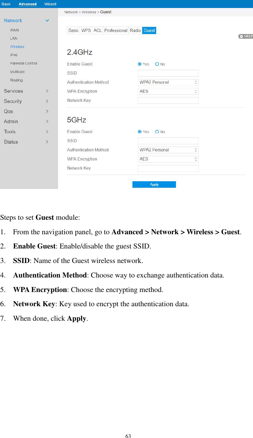
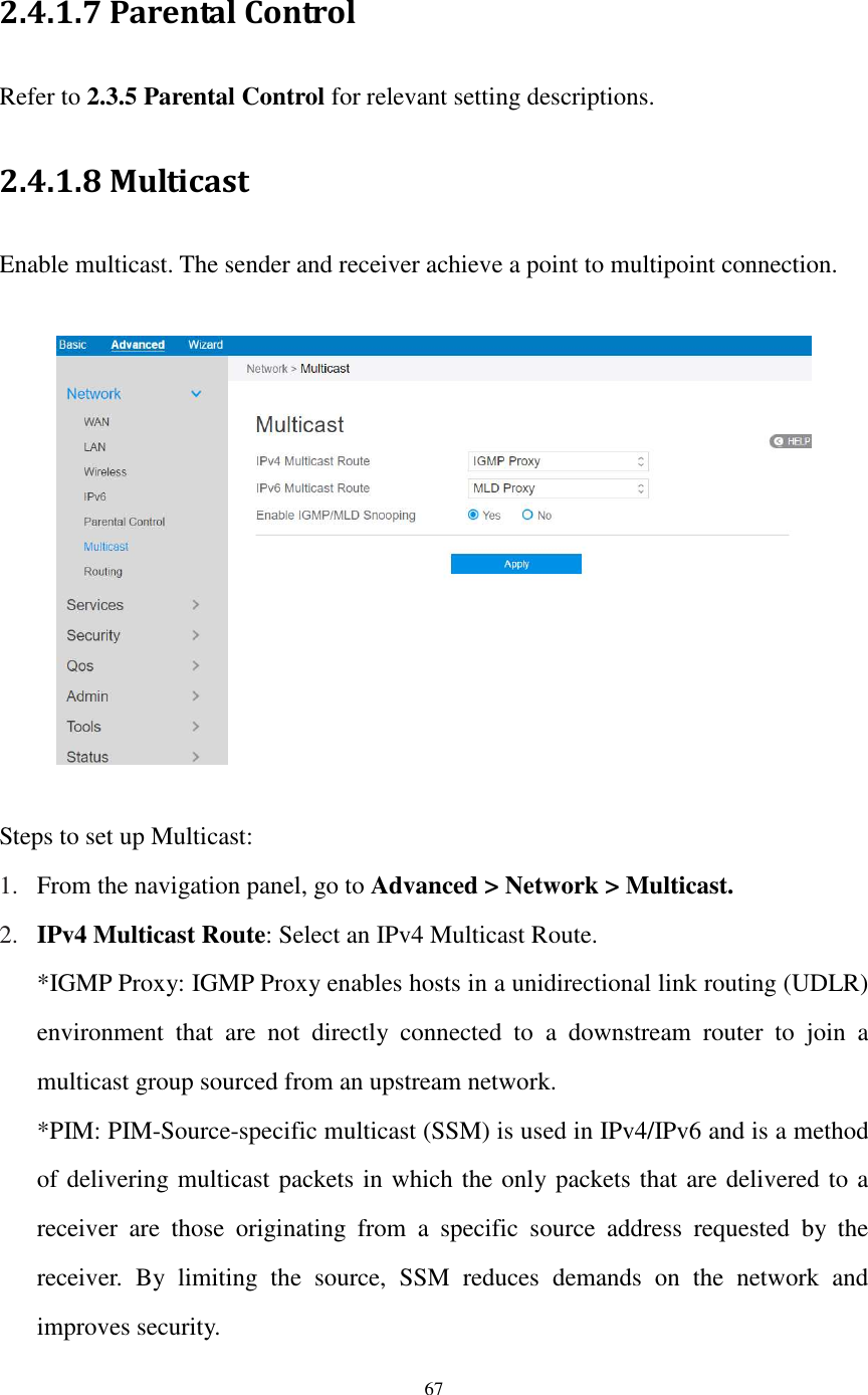
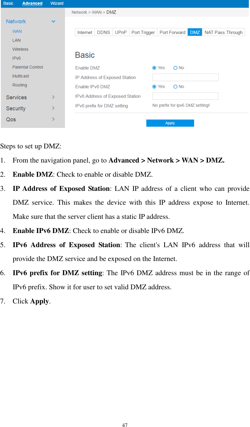
![68 3. IPv6 Multicast Route: Select an IPv6 Multicast Route. *MLD Proxy: The MLD proxy is used in IPv6 environments. This feature enables a device to learn proxy group membership information, and forward multicast packets based upon that information. If a device is acting as RP for route proxy entries, MLD membership reports for these entries can be generated on user specified proxy interface. 4. Enable IGMP/MLD Snooping: Check [Yes] to enable snooping and Check [No] to disable snooping. IGMP/MLD snooping is the process of listening to Internet Group Management Protocol (IGMP) / Multicast Listener Discovery (MLD) network traffic. The feature allows a network switch to listen in on the IGMP/MLD conversation between hosts and routers. By listening to these conversations the switch maintains a map of which links need which IP multicast streams. Multicasts may be filtered from the links which do not need them and thus controls which ports receive specific multicast traffic. 5. When done, click Apply.](https://usermanual.wiki/Askey-Computer/RAC2V1K/User-Guide-3305952-Page-69.png)
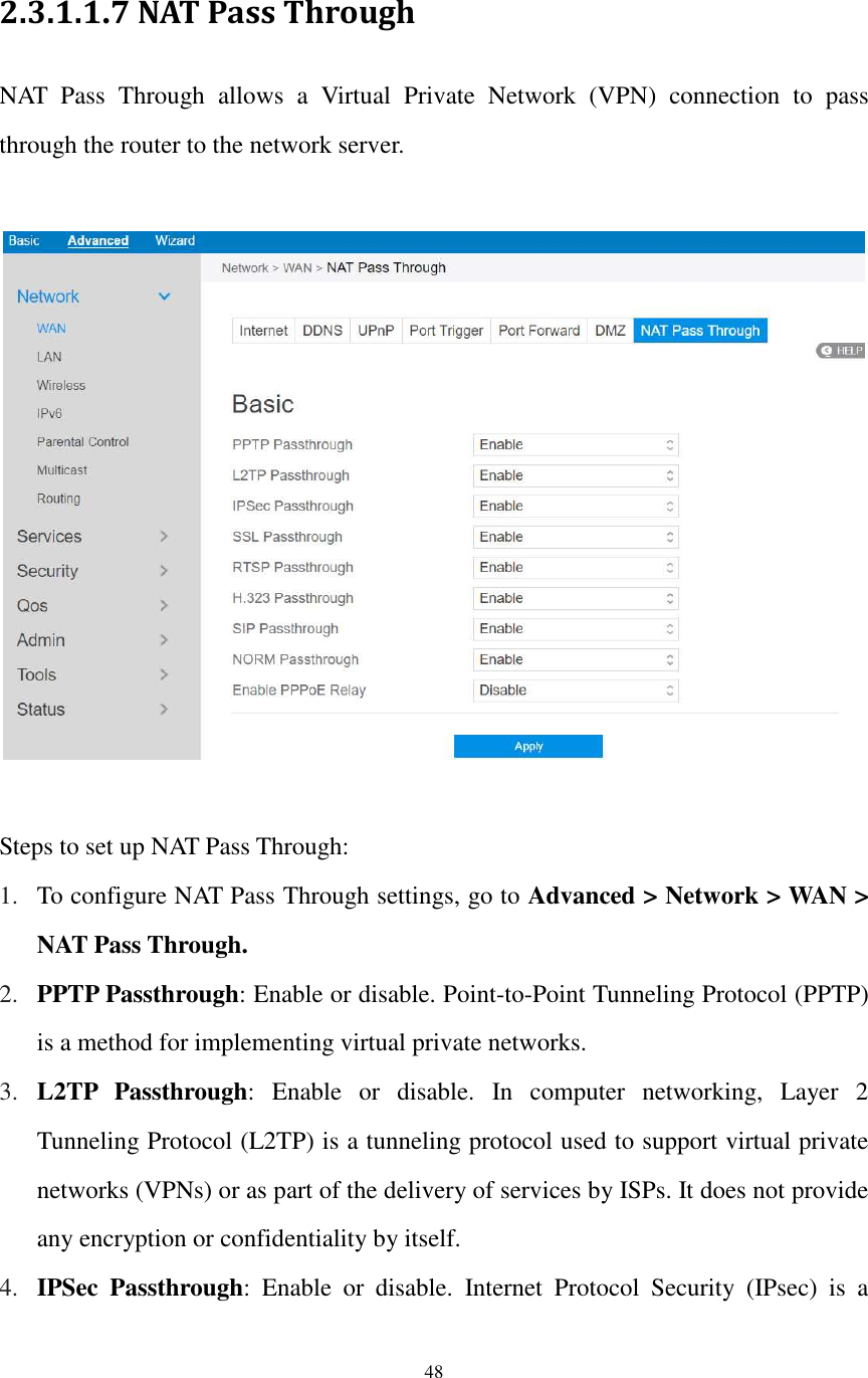
![69 2.4.1.9 Routing This module can be used to build a static NAT table between WAN IP address and LAN IP address. Steps to set up Routing: 1. From the navigation panel, go to Advanced > Network > Routing. 2. Enable 1:1 NAT: Check [Yes] to enable this function, check [No] to disable this function. 3. Name: A brief description for application. 4. Public IP: IP address from Charter supplied public IP subnets. 5. Local IP: Key in the client’s LAN IP address, not limited to the subnet for the directly connected LAN interface 6. Click On/Off to enable/disable Internet access to FTP service. 7. Click to add this item to the 1:1 NAT List. 8. Click Apply. NOTE: This module only works only when WAN port is in static mode!](https://usermanual.wiki/Askey-Computer/RAC2V1K/User-Guide-3305952-Page-70.png)
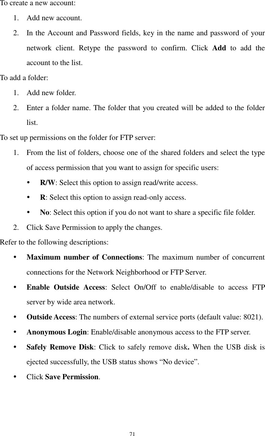
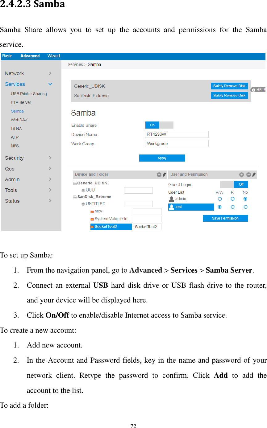
![73 1. Add new folder. 2. Enter a folder name. The folder that you created will be added to the folder list. To set up permissions on the folder for Samba server: 1. From the list of folders, choose one of the shared folders and add the share name, and choose the type of access permission that you want to assign for specific users: R/W: Select this option to assign read/write access. R: Select this option to assign read-only access. No: Select this option if you do not want to share a specific file folder. 2. Click Save Permission to apply the changes. Refer to the following descriptions: Device Name: Enter a name for your device and you can use this name in your web browser's URL field to quickly access the device as a Network Place service. Work Group: Group name of the cascade in Network Neighborhood. Note: The standard input characters include letters (A-Z, a-z), digits (0-9). The hyphen (-) and under line (_) characters may also be used, but not as the first character. Guest Login: By enabling [Guest Login], any user in your local network can access your network place (Samba) without authentication. Safely Remove Disk: Click to safely remove the disk. When the USB disk is ejected successfully, the USB status shows 'No device '. Click Save Permission.](https://usermanual.wiki/Askey-Computer/RAC2V1K/User-Guide-3305952-Page-74.png)
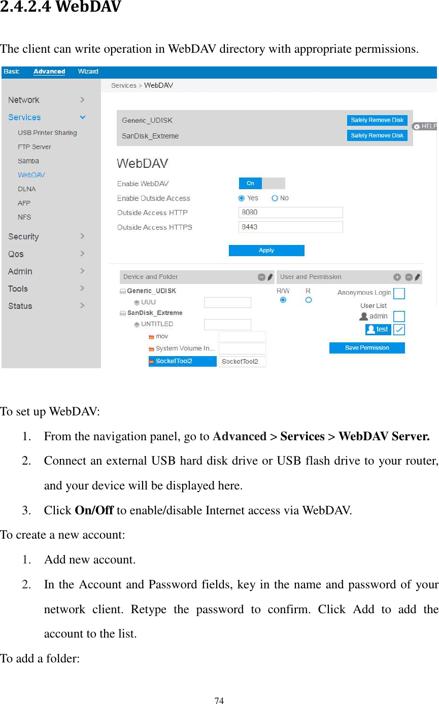
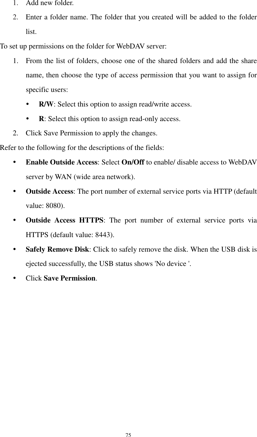
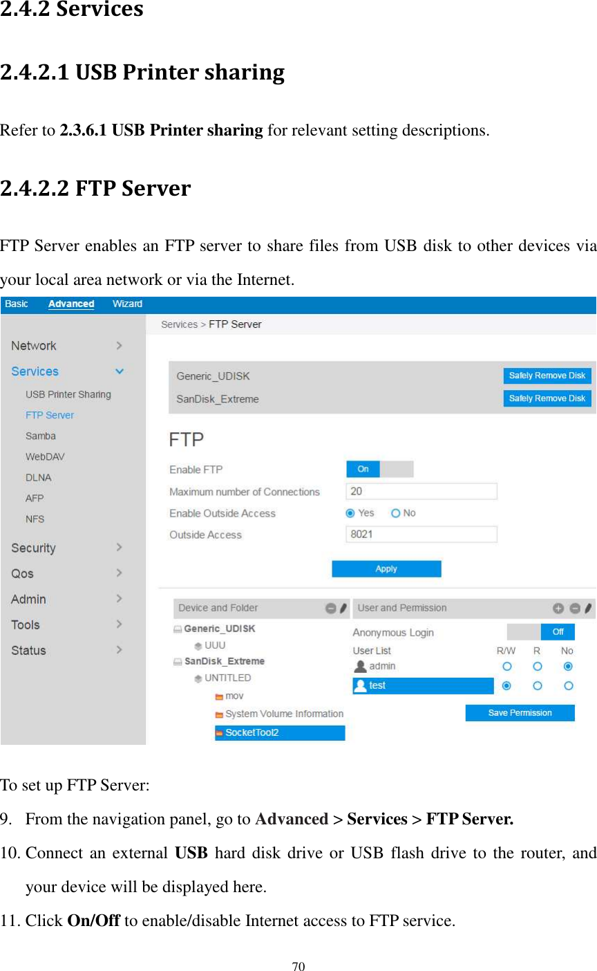
![78 1. Add new account. 2. In the Account and Password fields, key in the name and password of your network client. Retype the password to confirm. Click Add to add the account to the list. To add a folder: 1. Add new folder. 2. Enter a folder name. The folder that you created will be added to the folder list. To set up permissions on the folder for AFP server: 1. From the list of folders, choose one of the shared folder and add the share name, and choose the type of access permission that you want to assign for specific users: RW: Select this option to assign read/write access. R: Select this option to assign read-only access. No: Select this option if you do not want to share a specific file folder. 2. Click Save Permission to apply the changes. Refer to the following for the descriptions of the fields: Guest Login: By enabling [Guest Login], any user in your local network can access your network place (AFP) without authentication. Safely Remove Disk: Click to safely remove the disk. When the USB disk is ejected successfully, the USB status shows 'No device '. Click Save Permission.](https://usermanual.wiki/Askey-Computer/RAC2V1K/User-Guide-3305952-Page-79.png)
![85 2.4.3.1.3 VPN Client View the VPN server list and add profiles. There are three types of VPN servers: PPTP, L2TP and OpenVPN. Steps to setup a VPN Client: 1. From the navigation panel, go to Advanced > Security > VPN > VPN Client. 2. VPN Sever list is displayed. Click Add Profile to set up VPN Client. 3. VPN Server List: Current VPN Services which have been configured. 4. VPN Type: Type of VPN Server access such as PPTP, L2TP and OpenVPN. 5. Enable Default Route: Check [Yes] to use default route acquiring from VPN Server. Check [No] to use general default route. 6. Description: Enter a description for reference.](https://usermanual.wiki/Askey-Computer/RAC2V1K/User-Guide-3305952-Page-86.png)
![87 2.4.3.2 IPv4 Firewall Enable the firewall to protect local area network against attacks from outside. Firewall filters the incoming and outgoing packets based on rules. NOTE: Firewall is enable by default. 2.4.3.2.1 Common Steps to set up basic Firewall settings: 1. From the navigation panel, go to Advanced > Security > IPv4 Firewall > Common. 2. Enable Firewall: Disabling the firewall will deactivate all related functions. 3. Enable DoS Protection: A "denial-of-service" attack is an explicit attempt to deny legitimate users from using a service or computer resource. Enabling this feature can protect the router from DoS attack but it would increase the router's workload. 4. Respond to Ping Request from WAN: This feature allows router to make a response to ping request from WAN. 5. Enable IGMP: Check [Yes] to allow IGMP packages to be transferred to the](https://usermanual.wiki/Askey-Computer/RAC2V1K/User-Guide-3305952-Page-88.png)
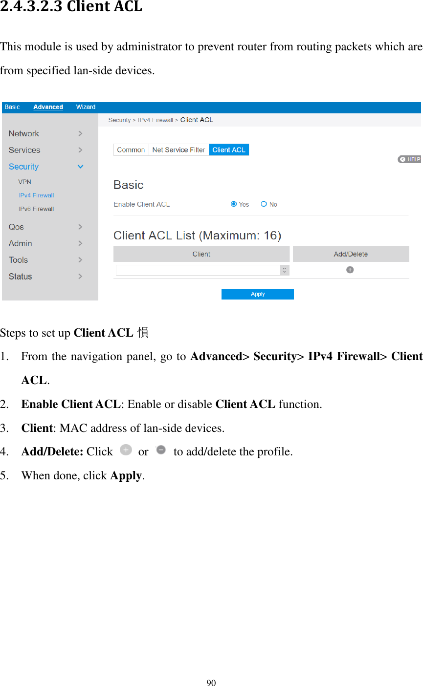
![88 router. Check No to deny IGMP packages. 6. Click Apply. 2.4.3.2.2 Net Service Filter Under the help of this module, administrator can set black list to block certain services, or set white list to let some services to pass through the router. Steps to set Net Service Filter 愪 1. From the navigation panel, go to Advanced> Security> IPv4 Firewall> Net Service Filter. 2. Enable Net Service Filter: Enable or disable this module. 3. Filter Table List: There are two kinds of filter list: White List, Black List. White List can make router serve the specified service defined in the list, Black List make router deny serving the specified service. 4. Filtered ICMP packet types: This field defines a list of LAN to WAN ICMP packets type that will be filtered. For example, if you would like to filter Echo (type 8) and Echo Reply (type 0) ICMP packets, you need to enter a string with numbers separated by blank, such as [0 8]. 5. Source IP: For source or destination IP address, you can: (a) enter a specific IP](https://usermanual.wiki/Askey-Computer/RAC2V1K/User-Guide-3305952-Page-89.png)
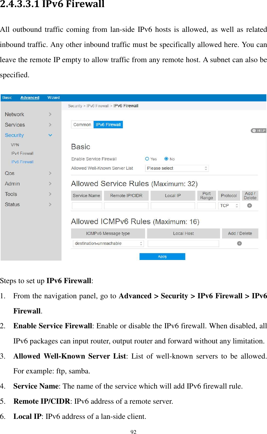
![91 2.4.3.3 IPv6 Firewall 2.4.3.3.1 Common Steps to set up common IPv6 Firewall: 1. From the navigation panel, go to Advanced > Security >IPv6 Firewall > Common. 2. Enable Firewall: Disabling the firewall will deactivate all related functions. 3. Respond to Ping Request from WAN: This feature allows router to make a response to ping request from WAN. 4. Enable MLD: Check [Yes] to allow MLD packages to be transferred to the router. Check [No] to deny MLD packages. 5. Click Apply.](https://usermanual.wiki/Askey-Computer/RAC2V1K/User-Guide-3305952-Page-92.png)
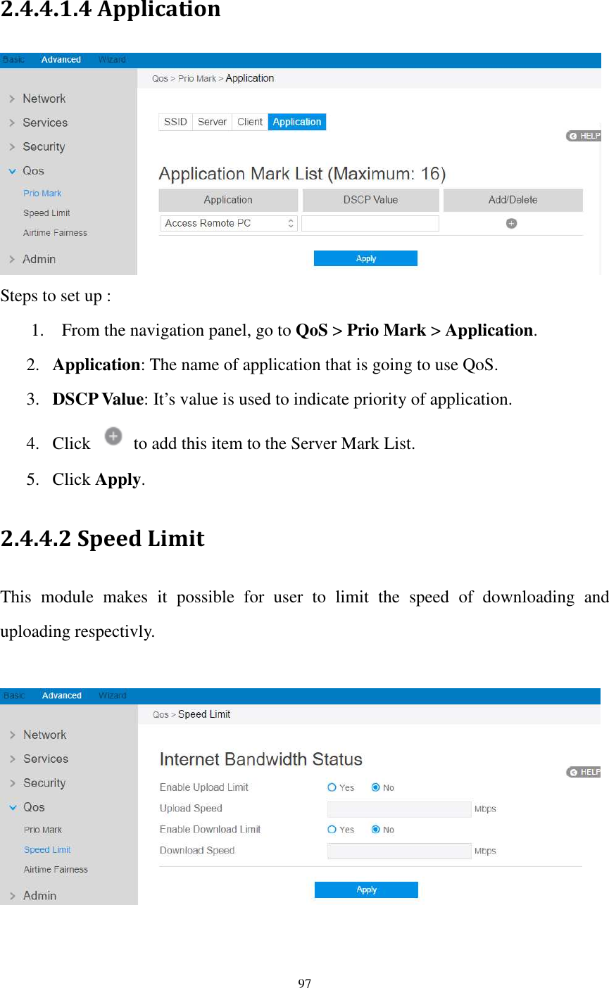
![98 Steps to set up Speed Limit: 1. From the navigation panel, go to QoS > Speed Limit. 2. Enable Upload Limit: . Check [Yes] to enable upload speed limit and Check [No] to disable upload speed limit. 3. Upload Speed: The highest speed that the router can provide for data uploading. 4. Enable Download Limit: Choose the wifi that is going to provide QoS. 5. Download Speed: The highest speed that the router can provide for data downloading. 6. Click Apply. NOTE: If speed of uploading or downloading set by you is beyond actual value provided by your ISP, your setting will take no effect 2.4.4.2 Airtime Fairness The ATF(Airtime Fairness, ATF) module supports mixing rates of WiFi devices to achieve better performance in busy/intense environments. Steps to set ATF:](https://usermanual.wiki/Askey-Computer/RAC2V1K/User-Guide-3305952-Page-99.png)
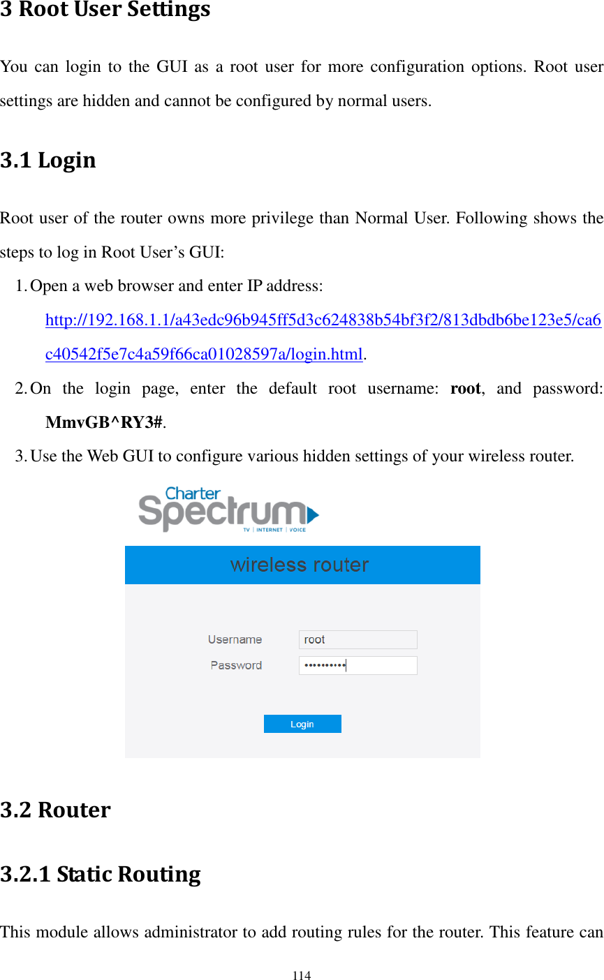
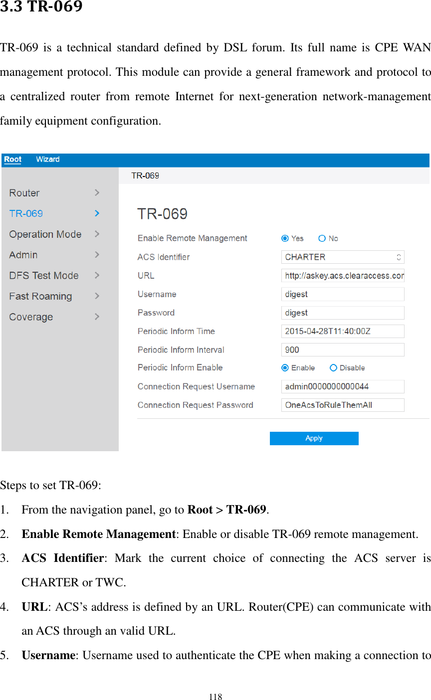
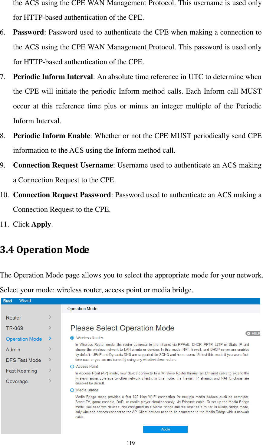
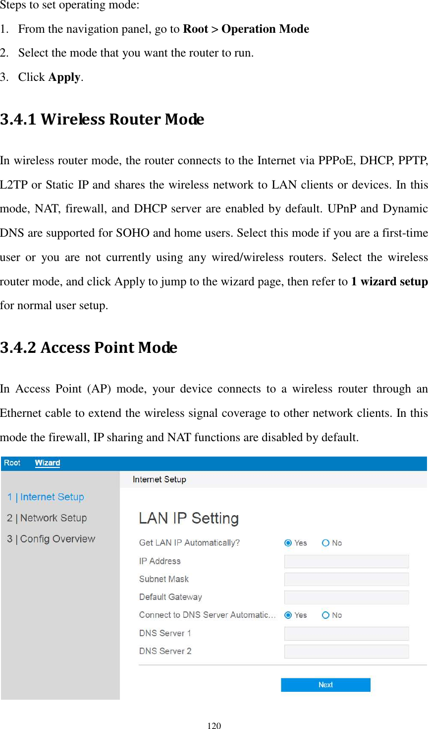
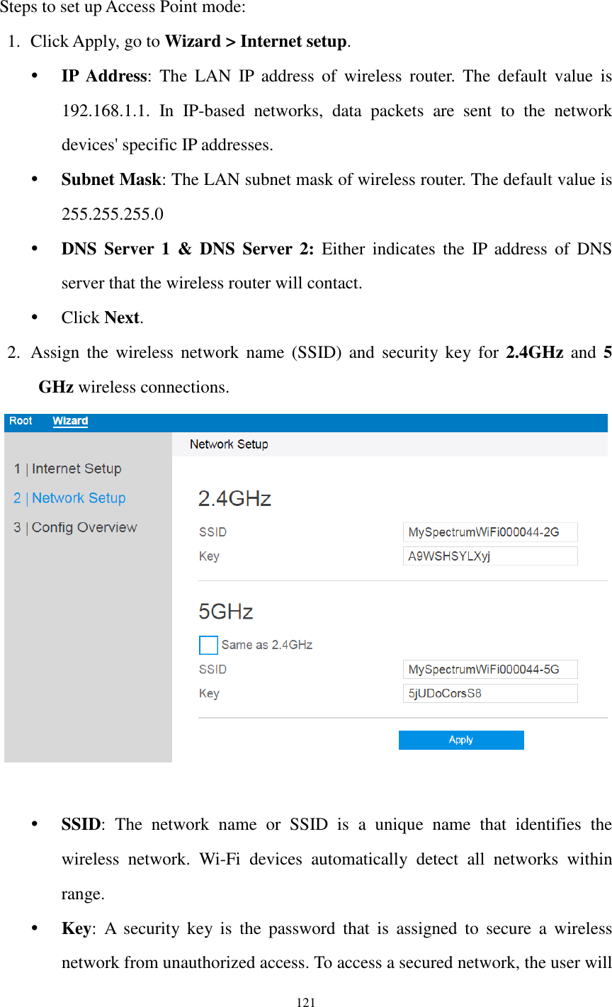
![115 be useful when there are several devices who are connecting with router. Steps to set Static Routing: 1. From the navigation panel, go to Root > Router > Static Routing. 2. Enable Static Routes: Select [Yes] to enable static routes. 3. Network/Host IP: The destination network or host of a route rule. It could be a host address such as '192.168.123.11' or a network address such as '192.168.0.0'. 4. Subnet Mask: Indicates how many bits are for network ID and subnet ID. For example: if the dotted-decimal Subnet Mask is 255.255.255.0, then its’ Subnet Mask bits is 24. If the destination is a host, its Subnet Mask bits should be 32. 5. Gateway: This is the IP address of the gateway where packets are routed to. The specified gateway must be setup and reachable first. 6. Metric: Metric is a value of distance for the network. 7. Interface: Network interface that the route rule will apply to. 8. Add/Delete: Click or to add/delete the profile. 9. When done, click Apply.](https://usermanual.wiki/Askey-Computer/RAC2V1K/User-Guide-3305952-Page-116.png)
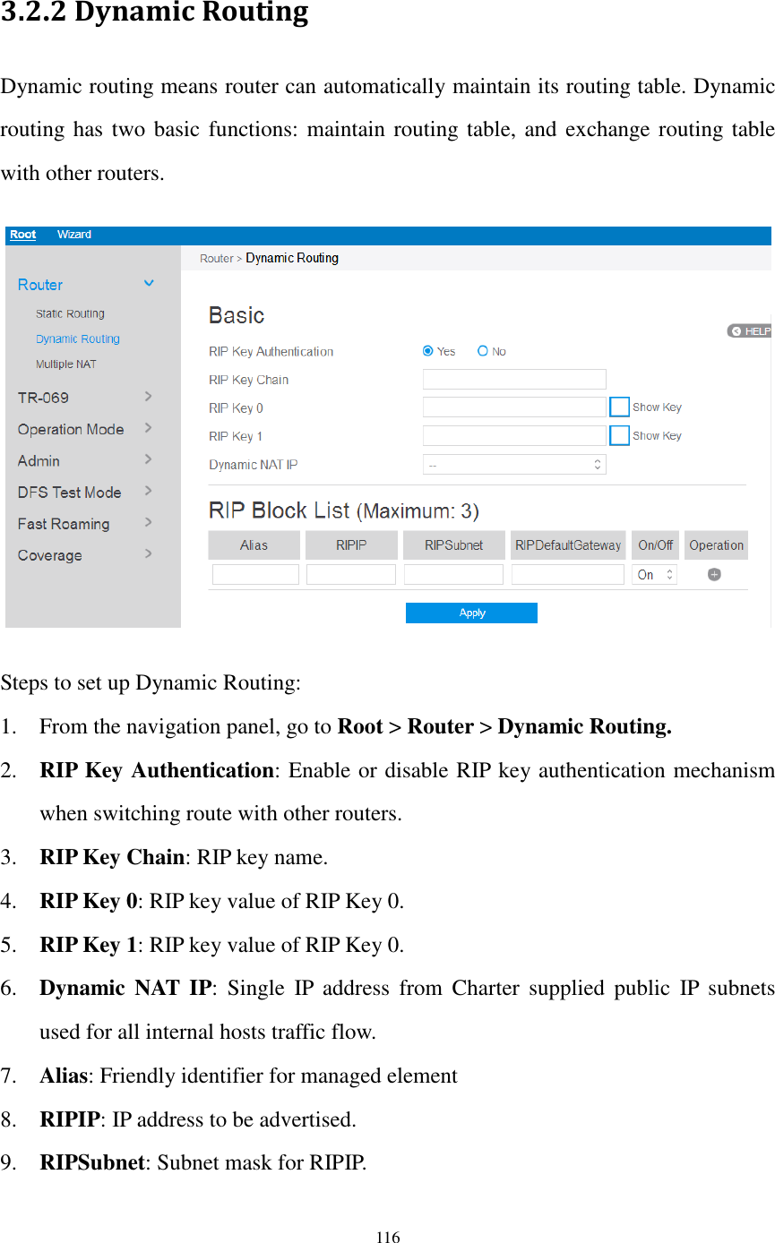
![117 10. RIPDefaultGateway: Gateway IP for RIPIP 11. On/Off: Enable or disable this item rule. 12. When done, click Apply. 3.2.3 Multiple NAT This can let you limit range of ipaddress that is going to use NAT function. Steps to set Multiple NAT: 1. From the navigation panel, go to Root > Router > Multiple NAT. 2. Enable Multiple NAT: Check [Yes] to enable this function, Check [No] to disable this function. 3. Name: The name for the item bar. 4. Public IP: IP address that Host IP will be mapped to. 5. Network/Host IP: IP address of the host reside on lan-side. 6. Subnet Mask: The subnet mask for lan-side IP address. 7. On/Off: Enable or disable the multiple NAT rule. 8. Click to add this item to the Multiple NAT List. 9. Click Apply.](https://usermanual.wiki/Askey-Computer/RAC2V1K/User-Guide-3305952-Page-118.png)