Askey Computer RAC2V1K DBDC ROUTER User Manual Spectrum WiFi User Manual draft ok
Askey Computer Corp DBDC ROUTER Spectrum WiFi User Manual draft ok
User Manual
Wireless Router
User Manual
1
Table of Contents
1 Hardware Setup ........................................................................................................... 3
1.1 Getting to know your router ................................................................................. 3
1.2 Unpack Router’s box ............................................................................................ 4
1.3 Hardware Features ............................................................................................... 5
1.3.1 Front Panel ..................................................................................................... 5
1.3.2 Rear Panel ...................................................................................................... 6
1.4 Position Your Router............................................................................................ 7
2 Normal User Settings .................................................................................................. 8
2.1 Login .................................................................................................................... 8
2.2 Wizard Setup ...................................................................................................... 10
2.3 Basic Setup ......................................................................................................... 17
2.3.1 My Router .................................................................................................... 17
2.3.2 WPS Setup ................................................................................................... 18
2.3.3 LAN Setup ................................................................................................... 20
2.3.4 WAN Setup ................................................................................................. 21
2.3.5 Parental Control ........................................................................................... 26
2.3.6 Services ........................................................................................................ 28
2.3.7 System ......................................................................................................... 37
2.4 Advanced Setup ................................................................................................. 38
2.4.1 Network ....................................................................................................... 38
2.4.2 Services ........................................................................................................ 70
2.4.3 Security ........................................................................................................ 80
2.4.4 QoS .............................................................................................................. 93
2.4.5 Admin ........................................................................................................ 100
2.4.6 Tools .......................................................................................................... 104
2.4.7 Status ......................................................................................................... 106
3 Root User Settings .................................................................................................. 114
3.1 Login ................................................................................................................ 114
2
3.2 Router ............................................................................................................... 114
3.2.1 Static Routing ............................................................................................ 114
3.2.2 Dynamic Routing ....................................................................................... 116
3.2.3 Multiple NAT ............................................................................................ 117
3.3 TR-069 ............................................................................................................. 118
3.4 Operation Mode ............................................................................................... 119
3.4.1 Wireless Router Mode ............................................................................... 120
3.4.2 Access Point Mode .................................................................................... 120
3.4.3 Media Bridge Mode ................................................................................... 122
3.5 Admin ................................................................................................... 125
3.5.1 System ....................................................................................................... 125
3.5.2 Firmware ............................................................................................... 126
3.6 DFS Test Mode ................................................................................................ 127
3.9 Fast Roaming ................................................................................................... 127
3.10 Coverage ........................................................................................................ 129
4.0 FCC Statement: ................................................................................................ 139
3
1 Hardware Setup
1.1 Getting to know your router
This product is designed for new flagship service: Managed Service Home Router.
Managed Service Home Router provides:
1. High performance:
Dual-Core ARM up to 1.7G/1GB DDR RAM.
Dual-Band wireless up to AC2550 (2.4G 200M * 4 + 5G 433M * 4).
Gigabyte 2x WAN/ 4x LAN Ethernet ports.
2. High security: Firewall/VPN supported.
3. Easy to setup: Friendly wizard, visual setup & maintenance (Basic Mode),
complete functions (Advanced Mode).
4. Easy to maintain: Supports TR069, TR181.
5. USB-based services: File/media/printer sharing.
The router is an ideal choice for residential and SOHO (Small Office/Home Office)
users who can enjoy a variety of wireless applications and services.
This chapter contains the following contents:
Unpack Your Router
Hardware Features
Position Your Router
4
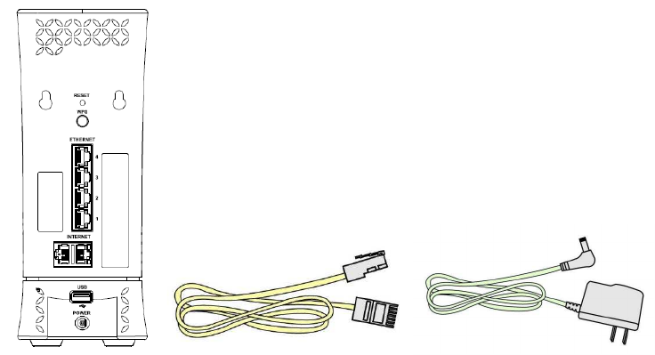
1.2 Unpack Router’s box
Open the box and remove the router, cables, and installation guide.
Wireless router Ethernet Cable Power Adapter
Figure 1. Check the package contents
The box contains the following items:
Wireless router.
AC power adapter (plug varies by region).
Ethernet cable.
Installation guide.
If any items are missing or damaged, please contact your dealer. Please keep original
packing materials in case you need to return the product for repairing.

5
1.3 Hardware Features
Before setup please take a moment to become familiar with the label and front, side,
and back panels of your router. Pay particular attention to the LED on the front panel.
1.3.1 Front Panel
The router front and side panels feature the status LED and buttons as shown in the
following figure.
Figure 2. Router front view
Front panel LED status
Off: Device off.
Blue quick blinking (0.4 second intervals): Booting up
Blue blinking 1 second intervals: Connecting to Internet
Blue solid: Connected to Internet.
Red blinking: Connectivity issues (no Internet
6
connection).
Red and Blue alternate blinking: Updating firmware
(or any scenario where device must not be restarted).
Red solid: Critical issues (hardware or otherwise).
LED on front of device will dim to low (65%) when there is no settings activity
or connectivity issues for 120 hours.
If any settings are changed or connectivity issues occur LEDs will return to
normal (100%) brightness.
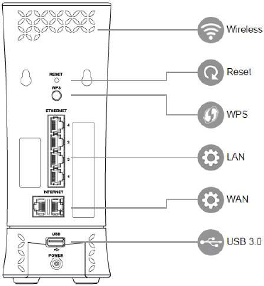
1.3.2 Rear Panel
There are slots and buttons shown in the following figure.
Figure 3. Router rear panel
Reset Button: Push the button and hold for over 15 seconds, then router will
restart automatically. During the process of restart, router will restore to factory
default settings.
WPS Button: Push the button more than 1 second to activate 2.4G and 5G WPS.
Reference WPS Setup on page 15.
LAN Port: Connect network cables for LAN (local area network) connections,
e.g. network switch, hub, personal computer or Internet devices.
7
WAN Port: Connect a network cable for WAN (Wide Area Network) connection.
This connects the Ethernet and other access lines e.g. modem.
USB 3.0 Port: Connect a USB Printer, U-Disk or USB drive. For printer and
folder sharing, reference Services on page 19.
Power Port(DC-IN): Use the bundled AC adapter to connect your router to a
power source.
1.4 Position Your Router
The router lets you access your network from virtually anywhere within the operating
range of your wireless network. However, the wireless communicating distance varies
significantly due to placement of the router. For example, the thickness and number of
walls the wireless signal passes through can limit the range. For best results, router is
likely to be place like this:
Near the center of the area where your computers and other devices operate, and
preferably within line of sight to your wireless devices.
So it is accessible to an AC power outlet and near Ethernet cables for wired
computers.
In an elevated location such as a shelf, keeping the number of walls and ceilings
between the router and your other devices to a minimum.
Away from electrical devices that are potential sources of interference.
Equipment that might cause interference includes ceiling fans, home security
systems, microwaves, computers, the base of a cordless phone, or a 2.4 GHz
cordless phone.
Away from any large metal surfaces, such as a solid metal door or aluminum
studs. Large expanses of other materials such as glass, insulated walls, fish tanks,
mirrors, brick, and concrete can also affect your wireless signal.
8
2 Normal User Settings
The wireless router contains an intuitive graphical user interface (GUI) based on web,
which allows administrator to easily configure its features through a web browser.
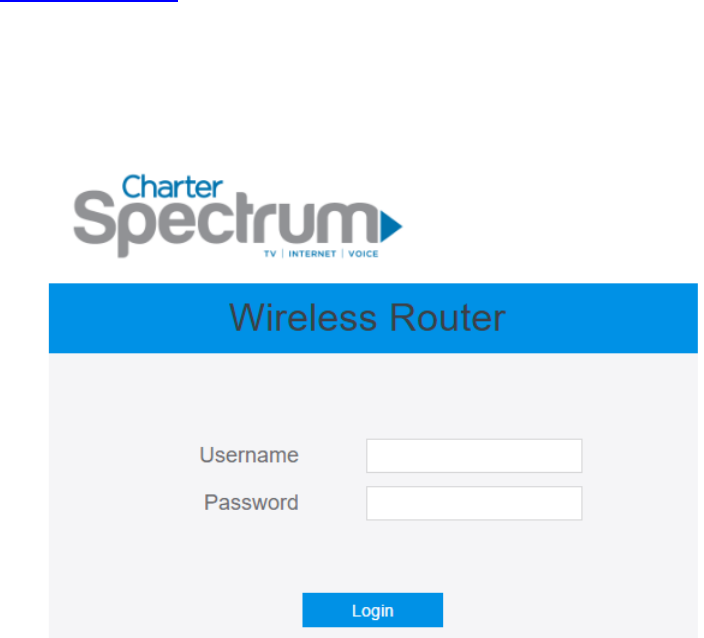
2.1 Login
1. Open a web browser, then key in the router’s default IP address:
http://192.168.1.1, and click Enter key in the keyboard;
2. On the login webpage, type in its default Username: admin and Password: admin,
then click Login button.
After administrator has logged in the router, some basic information on it will be
displayed by the browser.
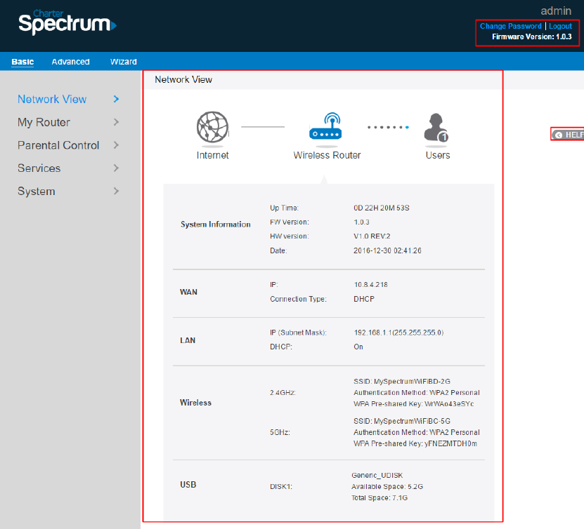
9
On the right top side, there are two command buttons: Change Password and Logout.
It’s highly recommended to click the Logout button who locates on the right top side
when administrator intends to leave the webpage.
When Change Password button has been clicked, the browser will navigate
administrator to corresponding webpage.
10
On this page, administrator should just type in new password in New Password and
Retype New Password, then click Apply button.
2.2 Wizard Setup
The wizard can navigate administrator to configure basic settings for wireless router,
which makes it become easy enough to set up the router.
Internet Setup
After administrator has clicked the Wizard button, the Internet Setup page will
come up.
Connection Type:
There are 5 kinds of connection type: DHCP, PPPoE, Static, PPTP, and L2TP.
Consult your ISP if you are unsure which kind of WAN connection type to select.
1. DHCP: Enable router to obtain IP addresses automatically. This type is usually
11
used by cable modem service providers.
WAN MAC: MAC address of WAN port. Some ISPs monitor devices’ MAC address
who are connecting to their networks, and only these devices with a valid MAC
address can be served. If router can’t get access to internet, administrator can do either
of the followings:
* Contact your ISP and request to update the MAC address associated with your
ISP subscription.
* Clone or change the MAC address of the new device to match the MAC address
of the original device.
Host Name: This field allows administrator to provide a name for router.
Usually it’s named by ISP.
DNS 1 & DNS 2: Either of them indicates the IP address of a DNS Server.
Click Next.
2. PPPoE: An Internet protocol provided by ISPs which requires a username and
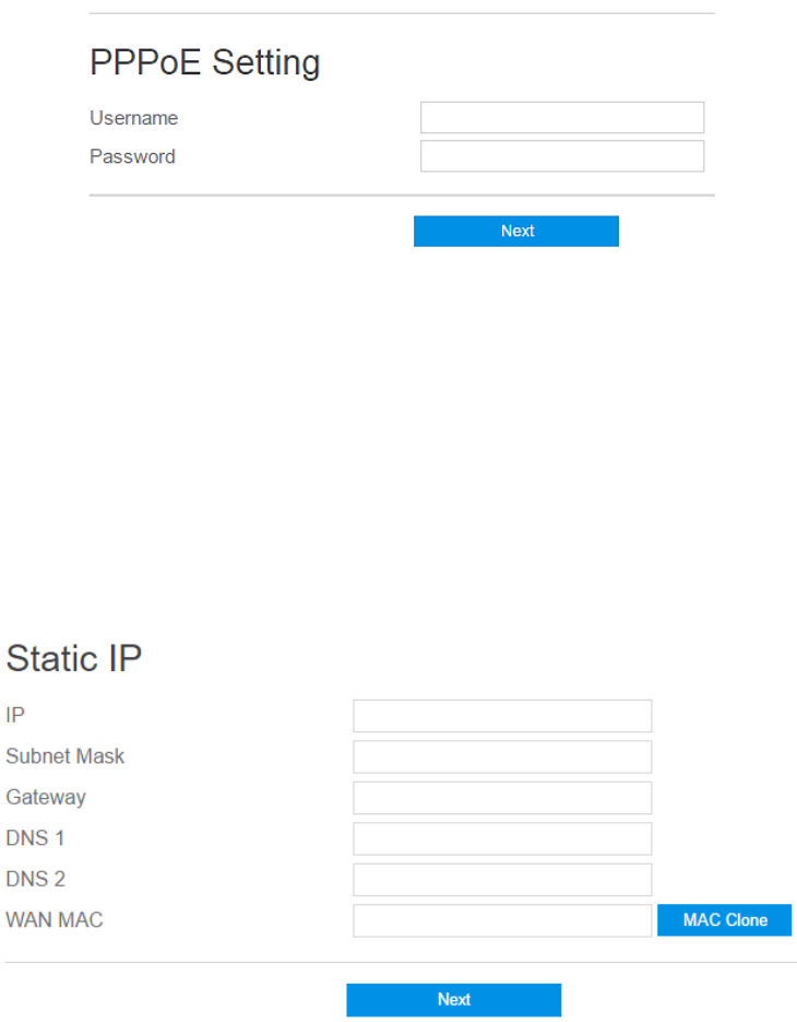
12
password. If you have no idea of the username and password, please contact
your ISP.
Username: This field is only available when you set the WAN Connection
Type as PPPoE, PPTP or L2TP.
Password: This field is only available when you set WAN Connection Type
as PPPoE, PPTP or L2TP.
Click Next.
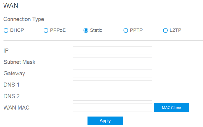
3. Static: Makes the router use a fixed IP address provided by your ISP. This
connection type is often used by ADSL service providers.
IP: Assigned by your ISP.
Subnet Mask: Assigned by your ISP.
Gateway: IP address of the gateway. Assigned by your ISP.
DNS 1 & DNS 2: Either of them indicates the IP address of DNS server that
the router will communicate with.
WAN MAC: MAC address is a unique identifier that identifies your
computer or device. ISPs monitor the MAC address of devices connecting to
13
their services, and will disallow Internet connection for invalid MAC
addresses.
Click Next.
Note: All of the parameters in Static IP connection type should be provided by your
ISP. If you have no idea of them, please ask the ISP for help.
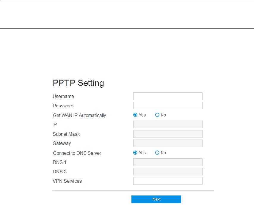
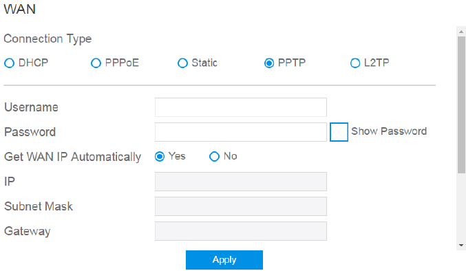
4. PPTP: A service provided by ISPs which requires a username, a password and/or
IP address.
Username: This field is only available when you set the WAN Connection
Type as PPPoE, PPTP or L2TP.
Password: This field is only available when you set WAN Connection Type
as PPPoE, PPTP or L2TP.
Get the WAN IP Automatically: Select Yes to get WAN IP automatically
and No to enter IP manually below.
IP: If your WAN connection requires a static IP address, key in the IP address
in this field.
Subnet Mask: If your WAN connection requires a static IP address, key in
the subnet mask in this field.
14
Gateway: If your WAN connection requires a static IP address, type in the
gateway IP address in this field.
Connect to DNS Server: Select Yes to let the device connect to a DNS
Server automatically, or No to enter DNS address manually below.
DNS1 & DNS2: Both present the IP address of the DNS server. If the device
can’t communicate with DNS1, it will try to communicate with DNS2.
VPN Services: IP address or DNS for VPN server.
Click Next.
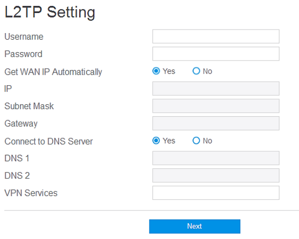
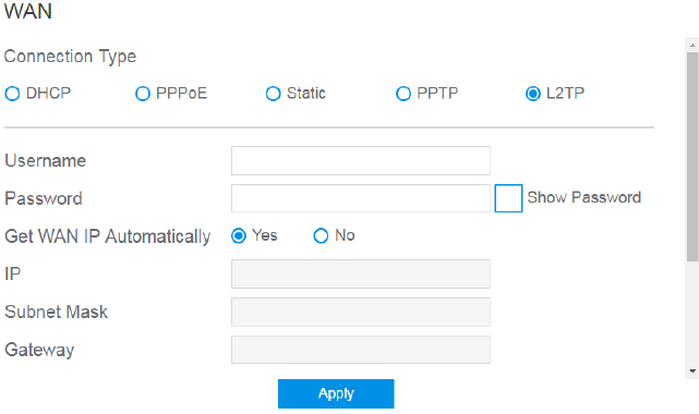
5. L2TP requires a username, password and/or IP address provided by your ISP.
Please reference to PPTP setting above.
15
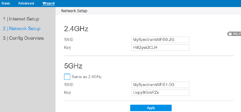
Network Setup
After you have clicked Next icon in Internet Setup page, you comes here.
1. SSID: Name for a wireless network, that’s to say it’s used to identify a wireless
network. Wi-Fi devices automatically detect all networks within its
communication range, if they own the key.
2. Key: A password used by router to authenticate wireless connections.
3. When done, click Apply.
16
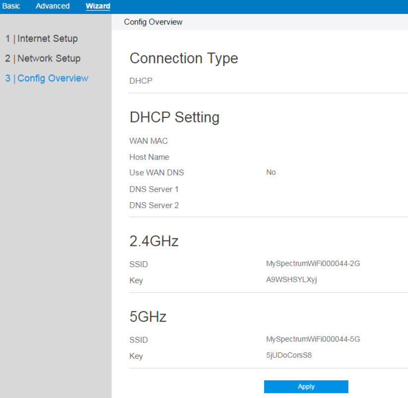
Config Overview
After click the Apply icon, administrator comes to Config Overview page, which
displays a summary of configuration information. If the settings are all correct,
administrator should click Apply icon.
17
2.3 Basic Setup
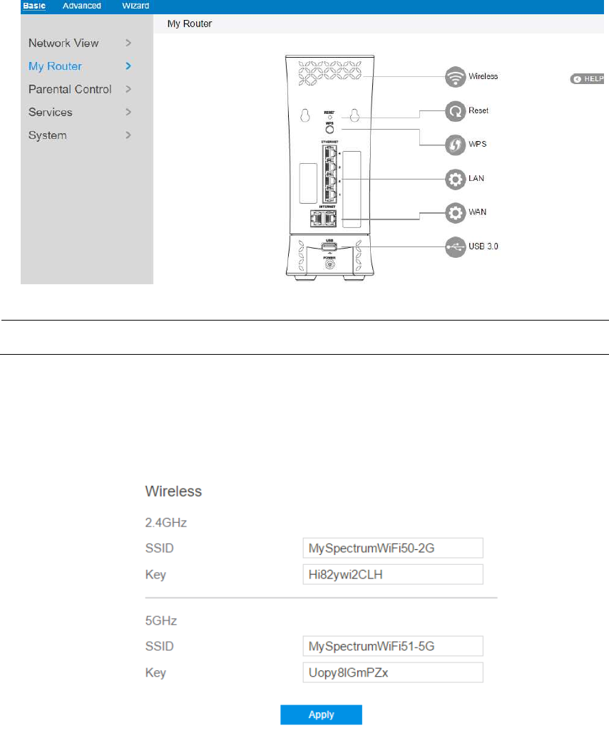
2.3.1 My Router
From the navigation panel, go to Basic > My Router.
Note: The Reset Icon in the picture is used to restart/reboot router manually!
Wireless: This module is implemented to configure some basic settings for router’s
wireless connection.
1. SSID: A unique name that identifies the wireless network. Wireless device can
18
automatically detect all networks within its communication range. The maximum
length of a SSID is 32 characters.
2. Key: A string used for connection authentication. Its length ranges from 0 to 63
characters(letters, numbers or a combination) or from 8 to 64 hex digits.
3. Click Apply.
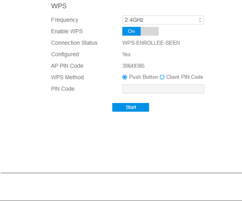
2.3.2 WPS Setup
WPS (Wi-Fi Protected Setup) is a wireless security standard that allows the device
easily connect to a wireless network. You can configure the WPS function via the PIN
code or WPS button.
Steps to enable WPS(Wi-Fi Protected Setup):
1. From the navigation panel, go to Basic > My Router.
2. Frequency: Selecting operating band (2.4 GHz or 5 GHz) for WPS function.
Note: If WPS has been enabled and administrator intends to change the frequency,
please disable WPS first.
3. Enable WPS: Selecting [On] to run WPS, witch simplifies the process of
connecting any device to the wireless network

19
Note: Authentication methods supported by WPS are: Open system, WPA-Personal
and WPA2-Personal. Not supported methods are: Shared Key, WPA-Enterprise,
WPA2-Enterprise and RADIUS.
4. Connection Status 愪The connection status of WPS.
5. Configured: The configured status of WPS.
6. AP PIN Code: Key in the router's PIN code in the client's WPS utility and
configure the network name and security settings.
7. WPS Method: Selects the method to per PIN (Personal Information Number)
method requires a PIN number to establish a wireless connection. PBC (Push
Button Configuration) method requires you to push a button (the Start button on
this page or a physical WPS button) to establish a wireless connection.
8. PIN Code: The WPS PIN code which clients use to connect with the router.
9. In the WPS Method field, select Push Button or Client PIN code. If you select
Push Button, go to step 10. If you select Client PIN code, go to step 11.
10. To set up WPS using the router’s WPS button, follow these steps:
a) Click Start or press the WPS button found at the rear of the wireless router.
b) Press the WPS button on your wireless device. This is normally identified
by the WPS logo.
NOTE: Check the wireless router or its user manual for the location of the WPS
button.
11. To set up WPS using the Client’s PIN code, follow these steps:
a) Locate the WPS PIN code on your wireless device’s user manual or on the
device itself.
b) Key in the Client PIN code on the text box.
c) Click Start to put your wireless router into WPS survey mode. The router’s
LED indicators quickly flash three times until the WPS setup is completed.
12. Click Start.
20
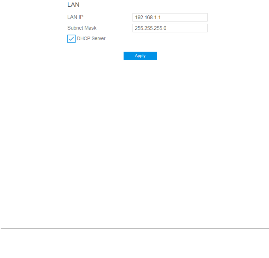
2.3.3 LAN Setup
This module makes it easier for administrator to modify the default LAN IP Address.
Steps to modify LAN IP settings:
1. From the navigation panel, go to Basic > My Router.
2. LAN IP: The LAN IP address of the wireless router. Its default value is
192.168.1.1. In IP-based networks, packets are sent to the network devices'
specific IP addresses.
3. Subnet Mask: Subnet mask of wireless router. Its default value is 255.255.255.0
4. DHCP Server: DHCP (Dynamic Host Configuration Protocol) is mostly used to
allocate IP address for lan-side devices. And a DHCP server can inform lan-side
deviced of DNS server’s address, default gateway IP and etc. This wireless router
can allocate 253 IP addresses at most.
NOTE: It’s recommended for administrator to select DHCP Server for LAN IP
setting. If not, administrator has to assign IP address to lan-side device manually.
5. Click Apply.
21
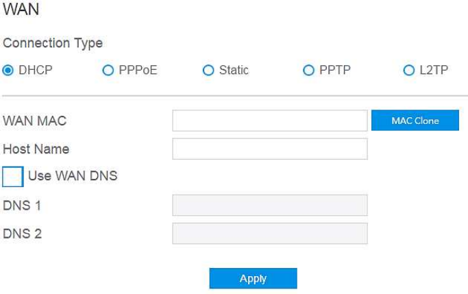
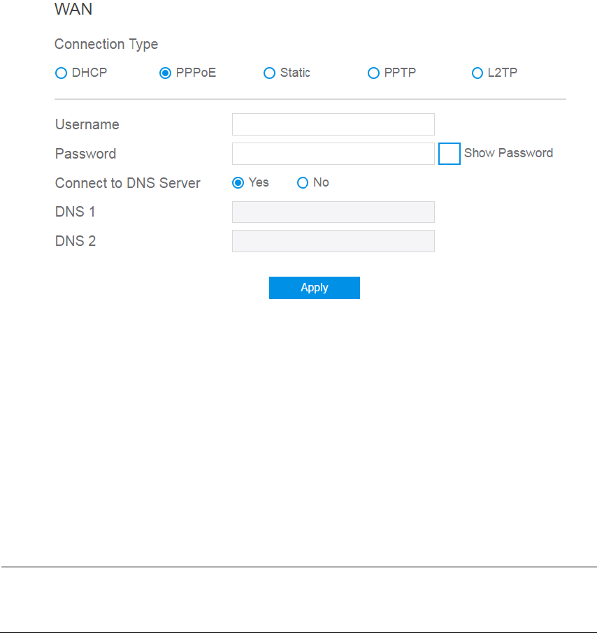
2.3.4 WAN Setup
Click WAN button to configure the WAN connection settings:
1. Connection Type: Choose the Internet Service type. There are five options are
DHCP, PPPoE, Static, PPTP, and L2TP. Consult your ISP if you are unsure what
kind of WAN connection type to select.
2. If you select DHCP:
WAN MAC: MAC (Media Access Control) address is a unique identifier that
identifies your computer or device in the network. ISPs monitor the MAC
addresses of devices that connect to their services, and would disallow
Internet connection for new MAC addresses.
To fix this issue, you can do either of the following:
* Contact your ISP and request to update the MAC address associated with
your ISP subscription.
* Clone or change the MAC address of the new device to match the MAC
address of the original device.
Host Name: This field allows you to provide a host name for wireless router.
Usually it’s provided by ISP.
22
DNS 1 & DNS 2: Either of them indicates IP address of a DNS server.
Click Apply.
3. If you select PPPoE:
Username: This field is only available when you set the WAN Connection
Type as PPPoE, PPTP or L2TP.
Password: This field is only available when you set WAN Connection Type
as PPPoE, PPTP or L2TP.
DNS1 & DNS2: Either of them indicates IP address of a DNS server that
wireless router will contact.
Click Apply.
NOTE: All of the parameters mentioned above are provided. If administrator has no
idea of these, please consult the ISP.
23
4. If you select Static, below show the steps to set
• IP: If WAN connection requires a static IP address, key in the IP address in
this field.
• Subnet Mask: If WAN connection requires a static IP address, key in the
subnet mask in this field.
• Gateway: If WAN connection requires a static IP address, key in the gateway
IP address in this field.
• DNS 1 & DNS 2: Either of them indicates IP address of a DNS server.
• WAN MAC: MAC (Media Access Control) address is a unique identifier
that identifies your computer or device in the network. ISPs monitor the
MAC addresses of devices that connect to their services, and would disallow
Internet connection for new MAC addresses.
To fix this issue, you can do either of the following:
* Contact your ISP and request to update the MAC address associated with
your ISP subscription.
* Clone or change the MAC address of the new device to match the MAC
address of the original device.
• Click Apply.
24
5. If you select PPTP:
• Username: This field is only available when you set the WAN Connection
Type as PPPoE, PPTP or L2TP.
• Password: This field is only available when you set WAN Connection Type
as PPPoE, PPTP or L2TP.
• Get the WAN IP Automatically: Select Yes to get WAN IP automatically
and No to enter IP manually below.
• IP: If WAN connection requires a static IP address, key in the IP address in
this field.
• Subnet Mask: If WAN connection requires a static IP address, key in the
subnet mask in this field.
• Gateway: If WAN connection requires a static IP address, key in the gateway
IP address in this field.
• Click Apply.
25
6. If you select L2TP:
Please reference to PPTP above for relevant settings descriptions and enter the
required information.
26
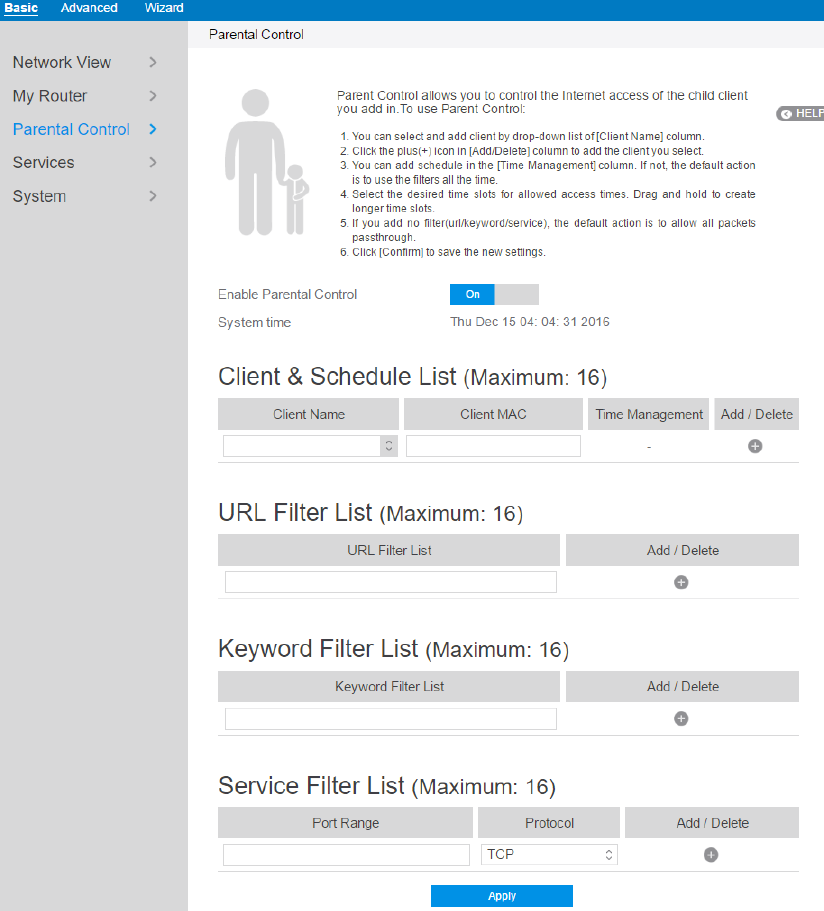
2.3.5 Parental Control
Parental Control allows administrator to control the behavior of the router.
Steps to set parental control function:
1. From the navigation panel, go to Base > Parental Control.
2. Enable Parental Control: Select On to enable parental control, Select Off to
disable parental control.

27
3. Client Name: Select client from the list. The name in the list stands for the client
that is communicating with the router.
4. Client MAC: MAC address of the selected client.
Note: Client Name just makes it easier for administrator to distinguish lan-side
devices. The Client MAC in fact specify the very device under parental control.
5. Add/Delete: Click or to add/delete the profile.
6. Time Management: Click , then setup the client’s schedule timetable to
allow or deny client’s access to Internet.
7. URL Filter List: Router prevents lan-side device from accessing the URL in list.
8. Add/Delete: Click or to add/delete the profile.
9. Keyword Filter List: Router prevents lan-side device from accessing to
webpages contain the keyword in list.
10. Add/Delete: Click or to add/delete the profile.
11. Service Filter List: Router prevents lan-side device from communicating with
remote device with defined port in Port Rang and defined Protocol.
12. Add/Delete: Click or to add/delete the profile.
13. Click Apply.
28
2.3.6 Services
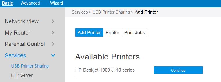
2.3.6.1 USB Printer Sharing
USB Printer sharing allows administrator to plug a USB printer to router’s USB port
and set up the print server.
Steps to set up USB Printer sharing:
1. From the navigation panel, go to Basic > Service > USB Printer sharing > Add
Printer.
2. Plug in the USB interface of the printer to the router. Confirm your printer has
been detected and click Continue.
3. Select one of the following modes to install the printer driver, and click Add
printer.
Auto select: Automatically searches for the appropriate printer driver and
installs. If there is no corresponding printer driver, the system displays add a
printer error; please select the correct printer driver manually.
Select printer driver: Manually select the corresponding printer brand and
model.
Choose PPD File: If the above methods are unable to correctly install the
printer driver, then you can upload a PPD File. Select your PPD file and click
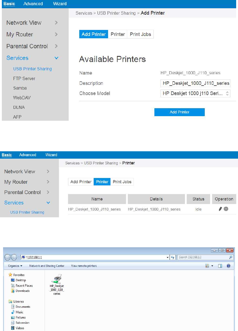
29
the upload button.
4. Printer tab displays whether your printer is operating correctly with the print
server, as below.
5. To check whether your printer is working correctly or not, input the LAN address
(192.168.1.1) for the printer in Windows Finder.
6. Double-click the printer icon and if you see the status interface as shown below,
the installation was successful. If an error message prompts that the driver
cannot be found, then return to Add Printer settings and select the correct
driver.
30
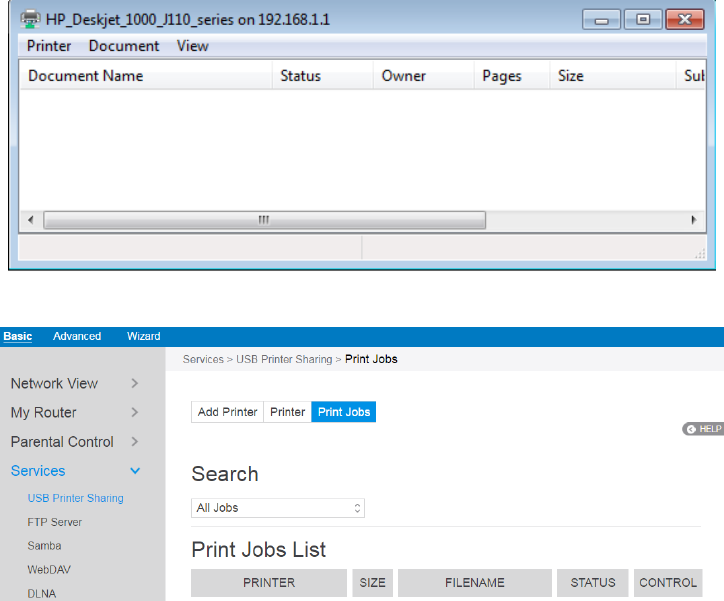
7. You can view print status information in the Print Jobs tab.
Active: All active jobs, including processing and pending jobs.
Processing: The job currently processing/communicating print data.
All Jobs: All print jobs.
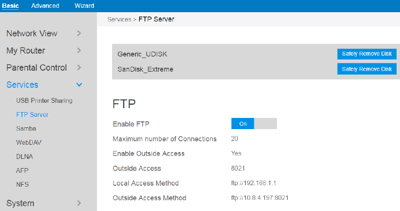
2.3.6.2 FTP Server
FTP Server enables an FTP server to share files from USB disk to other devices via
your local area network or via the Internet. This page shows information about the
FTP Server. For set up FTP Server, go to Advanced > Servers > FTP Server.
31
Display information on FTP Server:
1. From the navigation panel, go to Basic > Services > FTP Server.
2. Connect an external USB hard disk drive or USB flash drive to your router, and
your device will be displayed here.
3. Enable FTP: Click On/Off to enable/disable Internet access to FTP service.
4. Maximum number of Connections: the maximum number of concurrent
connections for the Network Neighborhood or FTP Server.
5. Enable Outside Access: Select On/Off to enable/disable access to FTP server by
wide area network.
6. Outside Access: The numbers of external service ports (default value: 8021).
7. Safely Remove Disk: Click to safely remove USB devices. When the USB disk is
ejected successfully, the USB status shows 'No device '.
2.3.6.3 Samba
Samba Share allows you to set up the accounts and permissions for the Samba service.
This page shows information about the Samba Server. For Samba setup go to
Advanced > Servers > Samba.
32
From the navigation panel, go to Basic > Services > Samba Server.
Connect an external USB hard disk drive or USB flash drive to your router, and
your device will be displayed here.
Enable Share: Click the On/Off to enable/disable Internet access to Samba
service.
Device Name: Enter a name for your device and you can use this name in your
web browser's URL field to quickly access the device as a Network Place service.
Work Group: Group name of the router in Network Neighborhood.
Safely Remove Disk: Click to safely remove the disk. When the USB disk is
ejected successfully, the USB status shows 'No device '.
33
2.3.6.4 WebDAV
The client can write operations in WebDAV directory with appropriate permissions.
This page shows information about the WebDAV Server. To set up WebDAV go to
Advanced > Servers > WebDAV.
1. From the navigation panel, go to Basic > Services > WebDAV Server.
2. Connect an external USB hard disk drive or USB flash drive to your router, and
your device will be displayed here.
3. HTTP Access Port: The port to access the WebDAV server for HTTP protocol in
34
the local area network (default value: 80).
4. HTTPS Access Port: The port to access the WebDAV server for HTTPS protocol
in the local area network (default value: 443).
5. Enable Outside Access: Select On/Off to enable/disable access to WebDAV
server by wide area network.
6. Outside Access: The port number of external service ports via HTTP (default
value: 8080).
7. Outside Access HTTPS: The port number of external service ports via HTTPS
(default value: 8443).
8. Safely Remove Disk: Click to safely remove the disk. When the USB disk is
ejected successfully, the USB status shows 'No device '.
2.3.6.5 DLNA
DLNA (Digital Living Network Alliance) allows you to share audio, image and video.
Your router allows DLNA-supported devices to access multimedia files from the USB
disk connected to your router. This page shows information about the DLNA Server.
To setup a DLNA server, go to Advanced > Servers > DLNA.
Steps to set DLNA:
1. From the navigation panel, go to Basic > Services > DLNA.
2. Connect an external USB hard disk drive or USB flash drive to your router, and
35
your device will be displayed here.
3. Enable DLNA Media Server: Switch DLNA media server on or off.
4. Media Server Name: The DLNA server's name, which will be displayed by the
media player such as VLC or Windows Media Player.
5. Safely Remove Disk: Click to safely remove the disk. When the USB disk is
ejected successfully, the USB status shows 'No device '.
2.3.6.6 AFP
An AFP server is a kind of network file sharing server based on AFP protocol
implementation, mainly used for file sharing between Linux and MAC systems. This
page shows information about the AFP server. To setup AFP, go to Advanced >
Servers > AFP.
Steps to set AFP:
1. From the navigation panel, go to Basic > Services > AFP.
2. Connect an external USB hard disk drive or USB flash drive to your router, and
your device will be displayed here.
3. Enable Share: Click On/Off to enable/disable AFP service.
4. Safely Remove Disk: Click to safely remove the disk. When the USB disk is
ejected successfully, the USB status shows 'No device '.
36
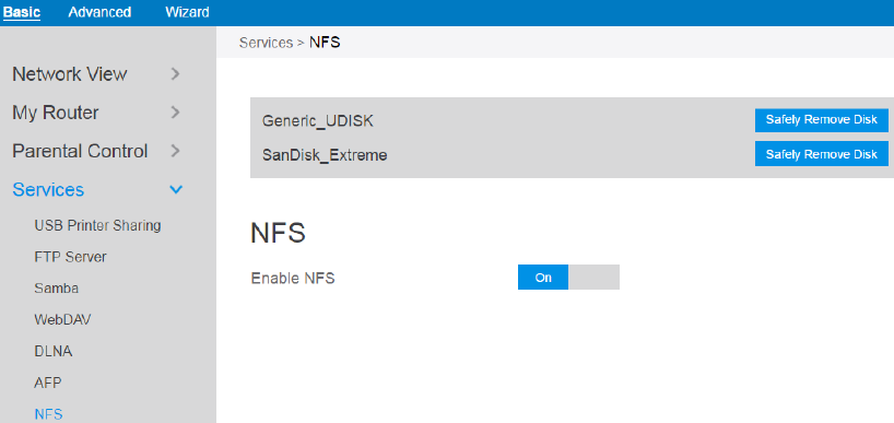
2.3.6.7 NFS
Network File System Server is used to share the USB disk with clients via network.
Clients can mount the remote disk to a local directory for a faster speed than using a
Samba server. This page shows information about the NFS Server. To setup NFS, go
to Advanced > Servers > NFS.
Steps to set NFS:
1. From the navigation panel, go to Basic > Services > NFS.
2. Connect an external USB hard disk drive or USB flash drive to the router, then
device’s name will be displayed here.
3. Enable NFS: Enable or disable NFS service. When disabled, users can't access
the USB storage via the NFS service.
4. Safely Remove Disk: Click to safely remove the disk. When the USB disk is
ejected successfully, the USB status shows 'No device '.

37
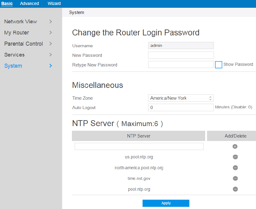
2.3.7 System
The system module allows administrator to configure router. Administrator can
change the username and password used to login to the router GUI and other
miscellaneous settings such as Time Zone, Auto Logout and NTP Server.
Steps to set the System settings:
1. From the navigation panel, go to Basic > System.
2. Username: name used to login router.
3. New Password: New login password for router.
4. Retype New Password: Retype new login password for router.
5. Time Zone: The time zone used by default.
6. Auto Logout: Auto logout after a specified period of time.
7. NTP Server: DNS of a NTP(Network Time Protocol) server.
38
8. Click Apply.
2.4 Advanced Setup
2.4.1 Network
2.4.1.1 WAN Settings
2.4.1.1.1 Internet Settings
Router supports several WAN connection types. Select the type from the WAN
Connection Type dropdown menu.
39
Steps to configure WAN connection settings:
1. From the navigation panel, go to Advanced > Network > WAN > Internet.
2. WAN Connection Type: Choose the Internet Service Provider type. There are 5
options: DHCP, PPPoE, Static , PPTP, and L2TP. If you are unsure which type
to select, please consult your ISP.
3. MTU: Maximum Transmission Unit value, which defines the maximum length of
a packet.
4. Connect to DNS Server: Allows router to get IP address from the DNS Server
automatically. DNS Server is a host on the Internet that translates Internet names
to numeric IP addresses.
5. Get WAN IP Automatically: Select Yes to get WAN IP automatically and No to
enter IP manually below.
6. IP Address: If your WAN connection requires a static IP address, key in the IP
address in this field.
7. Subnet Mask: If your WAN connection requires a static IP address, key in the
subnet mask in this field.
8. Default Gateway: If your WAN connection requires a static IP address, type in
the gateway IP address in this field.
9. DNS 1 & DNS 2: Either of them indicates an IP address of a DNS server.
10. Authentication: Use 802.1x MD5 authentication or not (IEEE 802.1x is an IEEE
Standard for port-based Network Access Control).
11. Username: Username for 802.1x MD5 authentication.
12. Password: Password for 802.1x MD5 authentication.
13. PPTP Options:
PPTP Encryption method. Select Auto for automatic Microsoft
Point-to-Point Encryption (MPPE) and select No Encryption to disable MPPE.
Select MPPE 40 for 40-bit MPPE with PPTP Server and select MPPE 128 for
128-bit MPPE with PPTP Server.
14. Access Concentrator Name: Specifies the Access Concentrator to connect to. If
40
unset, pppd uses the first discovered one.
15. Additional Pppd Options: Additional command line arguments to pass to the
pppd daemon.
16. Host Name: This field allows you to provide a host name for your router. It is
usually provided by ISP.
17. MAC Address: MAC address identifies a device in the network. ISPs monitor
the MAC addresses of devices that connect to their services, and would disallow
Internet connection for new MAC addresses.
To fix this issue, you can do either of the following:
* Contact your ISP and request to update the MAC address associated with your
ISP subscription.
* Clone or change the MAC address of the new device to match the MAC address
of the original device.
18. DHCP Query Frequency: Some ISP blocks MAC addresses if the device makes
DHCP queries too often. To prevent this, change the DHCP Query Frequency. In
the default Aggressive mode, if your wireless router does not get a response from
the ISP, it sends another query after 20 seconds and makes three more attempts.
In Normal mode, if your wireless router does not get a response from the ISP, it
makes a second query after 120 seconds and makes two more attempts.
19. Enable Default Route:
Whether to create a default route over the tunnel.
20. VPN Server: IP address or DNS for VPN server.
21. Click Apply.
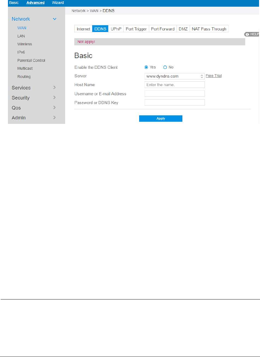
2.4.1.1.2 DDNS
Setting up DDNS (Dynamic DNS) allows you to get access to your router from
outside through the provided wireless router DDNS Service or another DDNS service.
41
Steps to set up DDNS:
1. From the navigation panel, go to Advanced > Network > WAN > DDNS.
2. Enable the DDNS Client: Yes means enable DDNS function, No means disable
DDNS function.
3. Server: Select the Supported DDNS provider’s URL from the list.
4. Host Name: Specifies the host name to be updated.
5. User Name or E-mail Address: User name or email address which has been
registered an account in a DDNS provider.
6. Password or DDNS Key: Password is your registered account.
7. Click Apply.
NOTES: DDNS service will not work properly under these conditions:
When the wireless router is using a private WAN IP address (192.168.x.x,
10.x.x.x, or 172.16.x.x), as indicated by yellow text.
The router works on a network who uses multiple NAT tables.
2.4.1.1.3 UPnP
UPnP (Universal Plug and Play) allows devices (such as routers, televisions, stereo
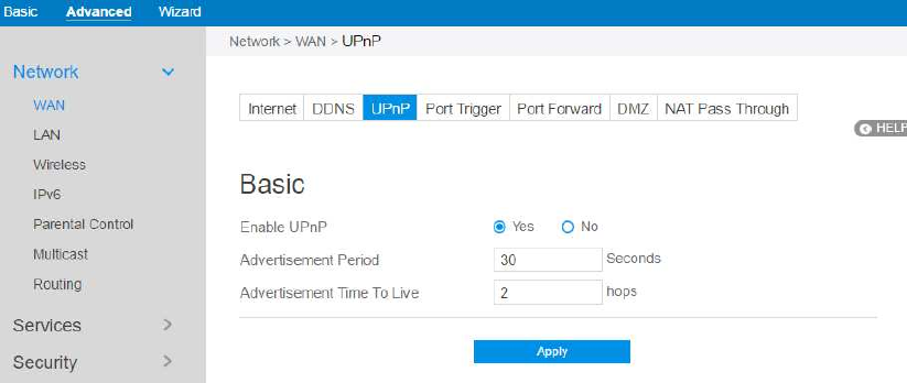
42
systems) to be controlled via an IP-based network with or without a central control
unit. Under the help of UPnP, one device can be discovered once it has connected to
network, then device can be remotely configured to support P2P applications,
interactive gaming, video conferencing, and web or proxy servers. Unlike Port
forwarding, UPnP automatically configures the router to accept incoming connections
and direct requests to a specific PC on the local network.
Steps to set up UPnP 愪
1. From the navigation panel, go to Advanced > Network > WAN > UPnP.
2. Enable UPnP: Yes means enable UPnP and No means disable it.
3. Advertisement Period: Router will broadcast its UPnP information to all devices
every advertisement-period seconds.
4. Advertisement Time To Live: Number of hops that an advertisement will be
transmited .
5. Click Apply.
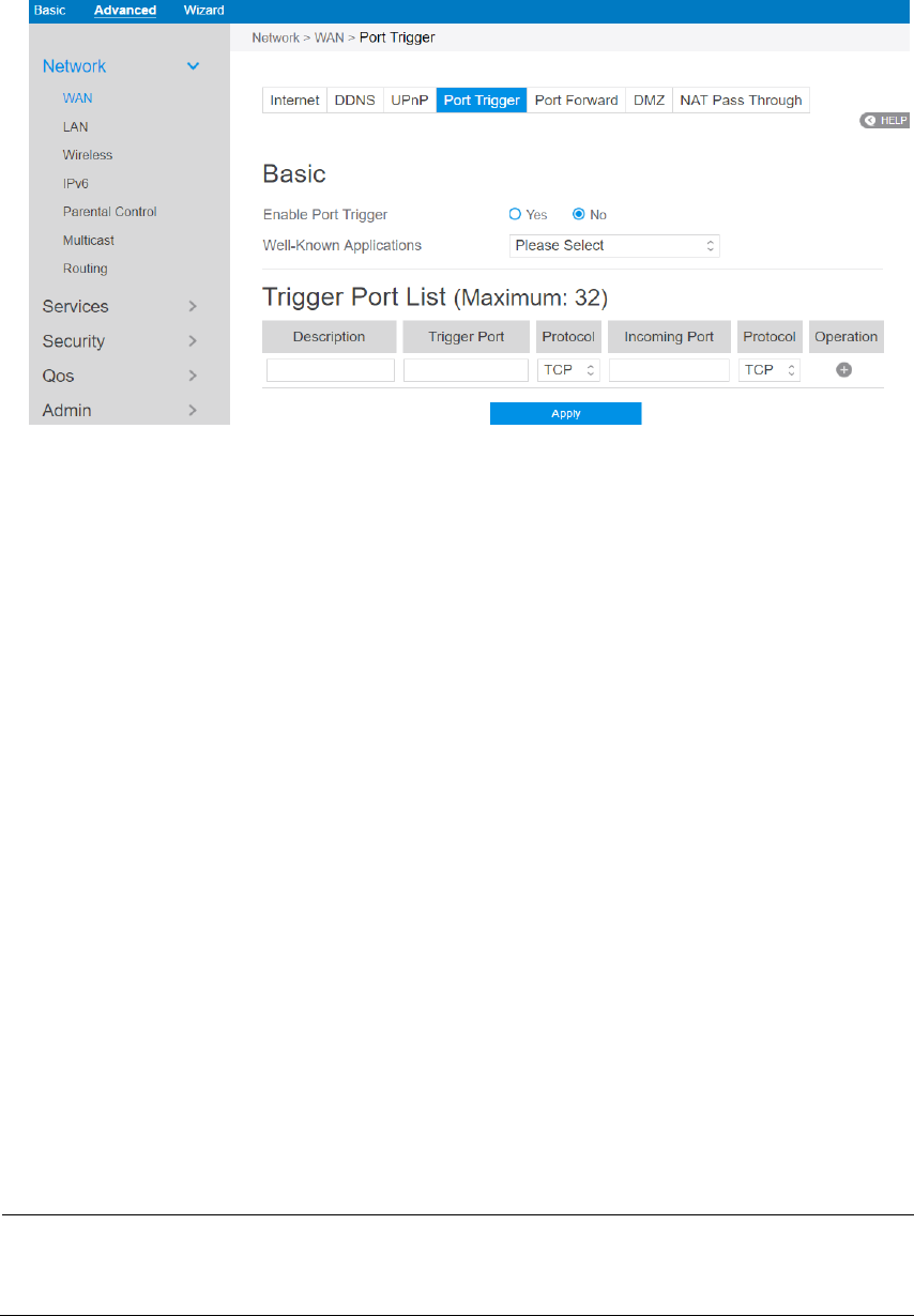
2.4.1.1.4 Port Trigger
Port trigger mechanism first defines a port (Trigger Port), when a lan-side device has
written data to this defined port, the incoming data from incoming port will be
forwarded to same port of the device who has activated this mechanism.
43
Steps to set up Port Trigger:
1. From the navigation panel, go to Advanced > Network > WAN > Port Trigger.
2. Enable Port Trigger: Check to enable or disable Port Triggering.
3. Well-Known Applications: Select popular games and web services to add to the
Port Trigger List.
4. Description: A brief description for application.
5. Trigger Port: When there is incoming data from lan-side application to this port,
the Port Trigger mechanism will be activated.
6. Protocol: Select the type of protocol that the application will use.
7. Incoming Port: Defines the range of port. After Port trigger mechanism has been
activated, the data from port within this range will be forwarded to the
corresponding port of the application who has activated Port trigger mechanism.
8. Operation: Add, Edit or Delete operation for this item.
9. Click Apply.
Note: Trigger Port element in the list is regarded as a trigger, that’s to say when data
comes to this port, the Port Trigger mechanism will be activated.
44
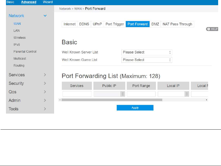
2.4.1.1.5 Port Forward
Port forwarding is a method used to direct network traffic from Internet to a specified
port. Setting up Port Forwarding allows traffic from outside to get access to specified
services provided by lan-side device.
NOTE: When Port Forward is enabled, router blocks unsolicited inbound traffic
from the Internet and only allows replies from outbound requests from the LAN. The
network client does not have access to the Internet directly, and vice versa.
Steps to set up Port Forwarding:
1. From the navigation panel, go to Advanced> Network> WAN>Port Forward.
2. Enable Port Forwarding: Check to enable or disable Port Forwarding.
3. Well Known Server List: Select a pre-defined Server list from the drop-down
menu and the Port Forwarding List will be auto-filled.
4. Well Known Game List: Select a game from the Server list and the Port
Forwarding List will be auto-filled.
5. Services: A short description about this service.
6. Public IP: IP address of WAN Port.

45
7. Port Range: Defines the range of port in wan side.
NOTES:
A network makes use of ports in order to exchange data, with each port assigned
a port number and a specific task. For example, port 80 is used for HTTP. A
specific port can only be used by one application or service at a time. Hence, two
PCs attempting to access data through the same port at the same time would fail.
For example, you cannot set up Port Forwarding for port 100 for two PCs at the
same time.
When your network’s firewall is disabled and you set 80 as the HTTP server’s
port range for your WAN setup, then your http server/web server would be in
conflict with the router’s web user interface.
8. Local IP: Key in the client’s LAN IP address.
9. Local Port: Enter a specific port to receive forwarded packets. Leave this field
blank if you want the incoming packets to be redirected to the specified port
range.
10. Protocol: The required protocol. Refer to the documentation for the service that
you are hosting.
11. Operation: Add, Edit or Delete operation for this item.
12. Click Apply
Steps to check whether Port Forwarding module has been activated successfully:
Ensure that your server or application is set up and running.
You will need a client outside your LAN which has Internet access (referred to as
“Internet client”). This client should not be connected to the wireless router.
On the Internet client, use the router’s WAN IP to access the server. If port
forwarding has been successful, you should be able to access
available/specified files or applications.
Differences between port trigger and port forward:

46
Port triggering will work even without setting up a specific LAN IP address.
Unlike port forwarding, which requires a static LAN IP address, port triggering
allows dynamic port forwarding using the router. Predetermined port ranges are
configured to accept incoming connections for a limited period of time. Port
triggering allows multiple computers to run applications that would normally
require manually forwarding the same ports to each PC on the network.
Port triggering is more secure than port forwarding since the incoming ports are
not open all the time. They are opened only when an application is making an
outgoing connection through the trigger port.
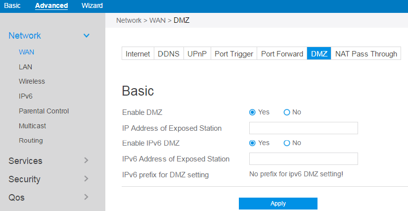
2.4.1.1.6 DMZ
Virtual DMZ module exposes one client to the Internet, allowing this client to receive
all inbound packets directed to a Local Area Network. Inbound traffic from the
Internet is usually discarded and routed to a specific client only if port forwarding or a
port trigger has been configured on the network. In a DMZ configuration, one
network client receives all inbound packets.
Setting up DMZ on a network is useful when you need incoming ports open or you
want to host a domain, web, or e-mail server.
CAUTION: Opening all of the client’s ports to Internet makes the network vulnerable
to outside attacks. Please be aware of the security risks involved in using DMZ.
47
Steps to set up DMZ:
1. From the navigation panel, go to Advanced > Network > WAN > DMZ.
2. Enable DMZ: Check to enable or disable DMZ.
3. IP Address of Exposed Station: LAN IP address of a client who can provide
DMZ service. This makes the device with this IP address expose to Internet.
Make sure that the server client has a static IP address.
4. Enable IPv6 DMZ: Check to enable or disable IPv6 DMZ.
5. IPv6 Address of Exposed Station: The client's LAN IPv6 address that will
provide the DMZ service and be exposed on the Internet.
6. IPv6 prefix for DMZ setting: The IPv6 DMZ address must be in the range of
IPv6 prefix. Show it for user to set valid DMZ address.
7. Click Apply.
48
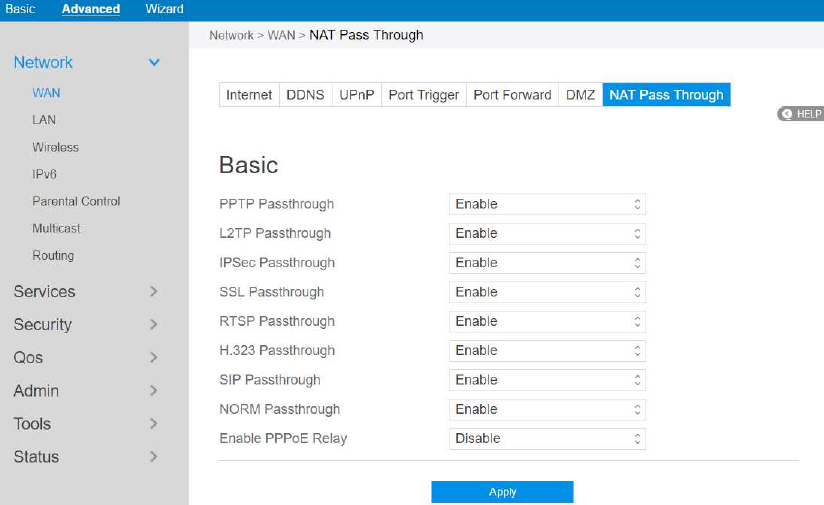
2.3.1.1.7 NAT Pass Through
NAT Pass Through allows a Virtual Private Network (VPN) connection to pass
through the router to the network server.
Steps to set up NAT Pass Through:
1. To configure NAT Pass Through settings, go to Advanced > Network > WAN >
NAT Pass Through.
2. PPTP Passthrough: Enable or disable. Point-to-Point Tunneling Protocol (PPTP)
is a method for implementing virtual private networks.
3. L2TP Passthrough: Enable or disable. In computer networking, Layer 2
Tunneling Protocol (L2TP) is a tunneling protocol used to support virtual private
networks (VPNs) or as part of the delivery of services by ISPs. It does not provide
any encryption or confidentiality by itself.
4. IPSec Passthrough: Enable or disable. Internet Protocol Security (IPsec) is a
49
protocol suite for securing Internet Protocol (IP) communications by
authenticating and encrypting each IP packet of a communication session.
5. SSL Passthrough: Secure Sockets Layer(SSL) is cryptographic protocols that
provide communications security over a computer network.
6. RTSP Passthrough: Enable or disable. The Real Time Streaming Protocol (RTSP)
is a network control protocol designed for use in entertainment and
communications systems to control streaming media servers.
7. H.323 Passthrough: Enable or disable. H.323 is a recommendation from the ITU
Telecommunication Standardization Sector (ITU-T) that defines the protocols to
provide audio-visual communication sessions on any packet network.
8. SIP Passthrough: Enable or disable. The Session Initiation Protocol (SIP) is a
communications protocol for signaling and controlling multimedia
communication sessions. The most common applications of SIP are in Internet
telephony for voice and video calls, as well as instant messaging all over Internet
Protocol (IP) networks.
9. NORM Passthrough: Enable or disable. NACK-Oriented Reliable Multicast
(NORM) Transport Protocol, which can provide end-to-end reliable transport of
bulk data objects or streams over generic IP multicast routing and forwarding
services.
10. Enable PPPoE Relay: PPPoE relay allows devices in LAN to establish an
individual PPPoE connection that passes through NAT.
11. When done, click Apply.
50
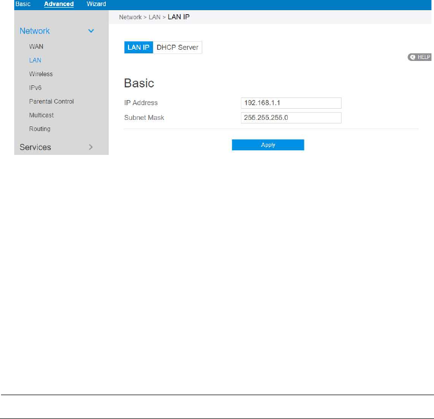
2.4.1.2 LAN Settings
2.4.1.2.1 LAN
The LAN IP module allows administrator to modify lan-side IP address of the router.
Steps to modify the LAN IP settings:
1. From the navigation panel, go to Advanced > Network > LAN > LAN IP.
2. IP Address: The LAN IP address of wireless router. The default value is
192.168.1.1. In IP-based networks, data packets are sent to the network devices'
specific IP addresses.
3. Subnet Mask: The LAN subnet mask of wireless router. Its default value is
255.255.255.0
4. Click Apply.
NOTE: Any change to the LAN IP module will affect router’s DHCP settings.
51
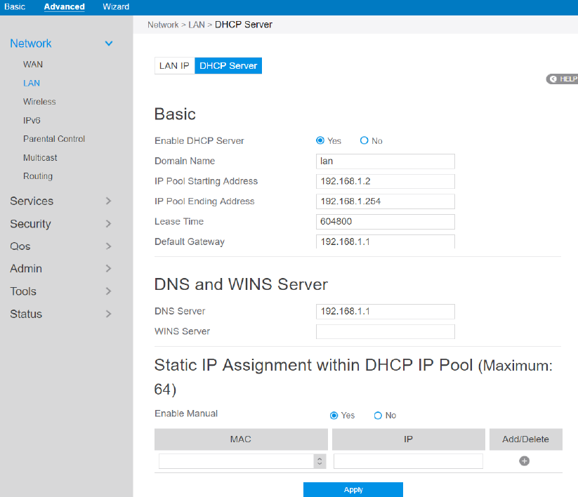
2.3.1.2.2 DHCP Server
DHCP server can assign each client an IP address and informs the client of DNS
server’s IP, default gateway’s IP and etc. This wireless router can allocate up to 253 IP
addresses for lan-side devices.
Steps to configure the DHCP server:
1. From the navigation panel, go to Advanced > Network > LAN > DHCP Server.
2. Enable DHCP Server: Enable DHCP server function which allows router to act
as a DHCP server to automatically assign IP addresses to network clients. If this
function is disabled, administrator has to manually set LAN devices.
3. Domain Name: Domain Name for clients who request IP Address from DHCP

52
Server. This field only contains alphanumeric characters and dash symbols.
4. IP Pool Starting Address: Starting address that can be allocated to lan-side
devices.
5. IP Pool Ending Address: Ending address that can be allocated to lan-side
devices.
6. Lease Time: Defines the time that lan-side devices can use the assigned IP
address. When the lease time expires, the network client will either send renew or
rebind message to a DHCP server.
7. Default Gateway: IP address of the gateway for LAN.
8. DNS Server: IP address of a DNS server. DNS Server is used to resolve a DNS
into a numerical IP Address. By default, the router will act as a DNS server.
9. WINS Server: Windows Internet Naming Service manages interactions of each
PC with the Internet. If you use a WINS server, enter the IP Address of server
here.
10. Enable Manual: Assign fixed IP address for clients.
11. MAC: MAC address of lan-side device.
12. IP: IP address within DHCP IP Pool for an-side device.
13. Add/Delete: Add/Delete static IP.
14. Click Apply.
NOTES:
• We recommend that administrator use an IP address format of 192.168.1.xxx (where
xxx can be any number between 2 and 254) when specifying an IP address range.
• An IP Pool Starting Address should not be greater than the IP Pool Ending Address.
53
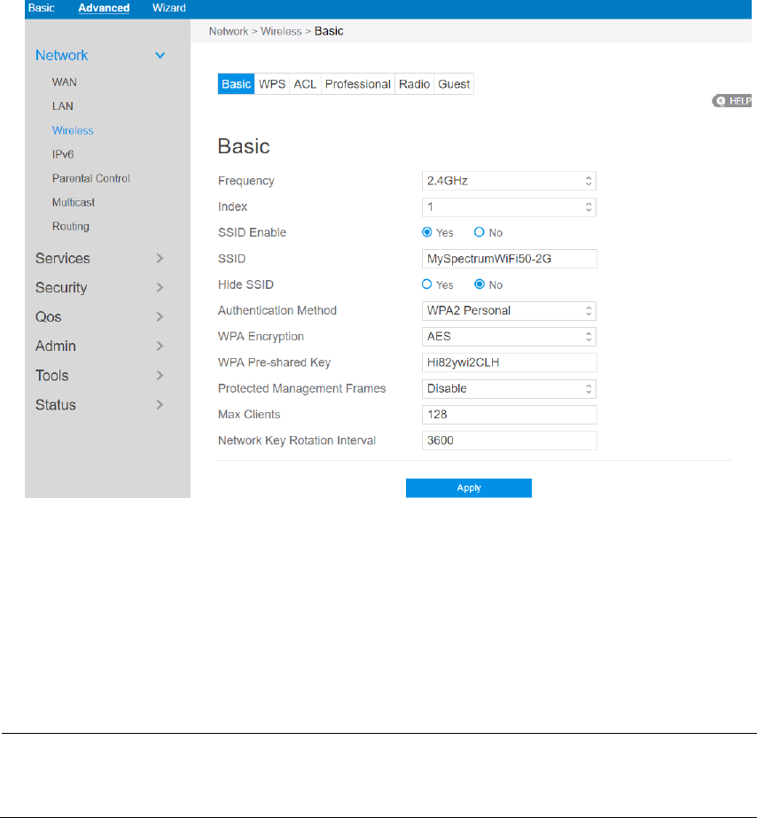
2.4.1.3 Wireless Settings
2.4.1.3.1 Basic
Basic settings allow you to set up the basic wireless settings.
Steps to set up the basic wireless settings:
1. From the navigation panel, go to Advanced > Network > Wireless > Basic
BasicBasic
Basic.
2. Frequency: Select the frequency band to configure.
3. Index: Indicates witch SSID is under setting.
Note: At present time, the router supports 8 SSIDs. So, router uses Index parameter to
indicate witch SSID is under configuration.
4. SSID Enable: Switch the SSID on/off (enable/disable).
54
5. SSID: A name whose length is less than 32 characters is used to identify a
wireless network. WiFi devices automatically detect all networks within its
communication range.
6. Hide SSID: If [Yes] is selected, SSID does not show in site surveys by wireless
mobile clients and they can only connect to wireless router by manually entering
SSID.
7. Authentication Method: This field enables authentication methods for wireless
clients.
8. WPA Encryption: Enable WPA Encryption to encrypt data.
9. WPA Pre-Shared Key: Requires a password of 8-63 characters (letters, numbers
or a combination) or 8 - 64 hex digits to start the encryption process.
10. Protected Management Frames: Protected Management Frames is a feature to
protect some types of management frames like deauthorization, disassociation
and action frames.
11. Max Clients: The maximum number of clients allowed.
12. Network Key Rotation Interval: This field specifies the interval (in seconds)
after which a WPA group key is changed. Enter [0] (zero) to indicate that a
periodic key-change is not required. Please input the value between 600 to 86400
(seconds).
13. Click Apply.
55
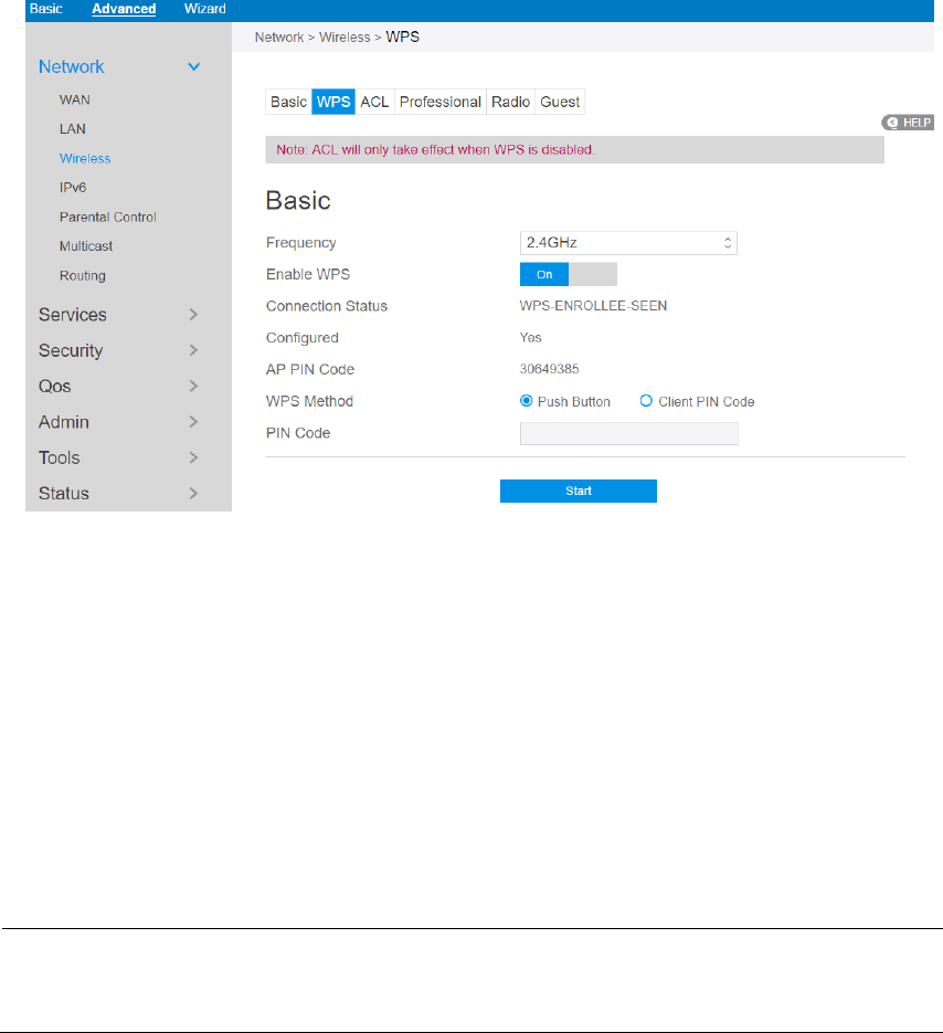
2.4.1.3.2 WPS
WPS (Wi-Fi Protected Setup) is a wireless security standard that allows you to easily
connect devices to a wireless network. You can configure the WPS function via the
PIN code or WPS button. WPS supports the authentication of Open system,
WPA-Personal and WPA2-Personal. Not supported: Shared Key, WPA-Enterprise,
WPA2-Enterprise and RADIUS.
Steps to set WPS:
1. From the navigation panel, go to Advanced > Network > Wireless > WPS.
2. Frequency: Select an operating band (2.4 GHz or 5 GHz) for WPS. To change
the operating band, please disable the WPS function first.
3. Enable WPS: Selecting [On] to enable WPS. This can simplify the process of
connecting any device to the wireless network.
NOTE: WPS supports authentication using Open System, WPA-Personal, and
WPA2 - Personal. WPS does not support a wireless network that uses a Shared Key,

56
WPA-Enterprise, WPA2-Enterprise, and RADIUS encryption method
4. Connection Status: The connection status of WPS.
5. Configured: The configured status of WPS.
6. AP PIN Code: This is your router’s WPS PIN code. Enter this in the client's WPS
utility to make a connection.
7. WPS Method: PIN (Personal Information Number) method requires you to enter
a PIN number to establish a wireless connection. PBC (Push Button
Configuration) method requires you to push a button (the Start button on this
page or a physical WPS button) to establish a wireless connection.
8. To set up WPS using the router’s WPS button:
a) Click Start or press the WPS button found at the rear of the wireless router.
b) Press the WPS button on your wireless device. This is normally identified by
the WPS logo.
NOTE: Check your wireless device or its user manual for the location of the WPS
button.
9. To set up WPS using the Client’s PIN code:
a) Locate the WPS PIN code on your wireless device’s user manual or on the
device itself.
b) Key in the Client PIN code on the text box.
c) Click Start to put your wireless router into WPS survey mode. The router’s
LED indicators quickly flash three times until the WPS setup is completed.
10. PIN Code: The WPS PIN code for clients to connect using PIN method.
11. When done, click Start.
57
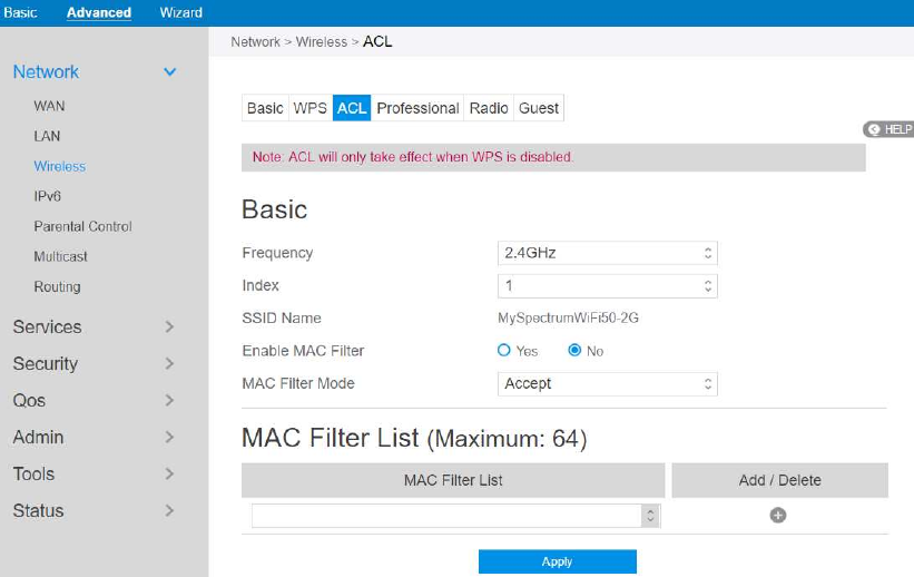
2.4.1.3.3 ACL
ACL can be used to allow or disallow one device to send packets.
Steps to set up the ACL:
1. From the navigation panel, go to Advanced > Network > Wireless > ACL.
2. Frequency: In the frequency field, select the frequency band that you want to use
for the ACL settings.
3. Index: Indicate witch SSID is going to apply ACL rules.
4. SSID Name: A name whose length is less than 32 characters is used to identify a
wireless network.
5. Enable MAC Filter: Enable MAC filter or disable.
6. MAC Filter Mode: Select Accept to allow devices in the MAC filter list to
access to the wireless network, select Reject to prevent devices in the MAC filter
list from access to the wireless network.
7. MAC Filter List: Enter the MAC address of the wireless device. MAC filtering
allows users to either limit specific MAC addresses from associating with the
58
AP/router, or specifically indicates which MAC addresses can associate with the
AP/router.
8. When done, click Apply.
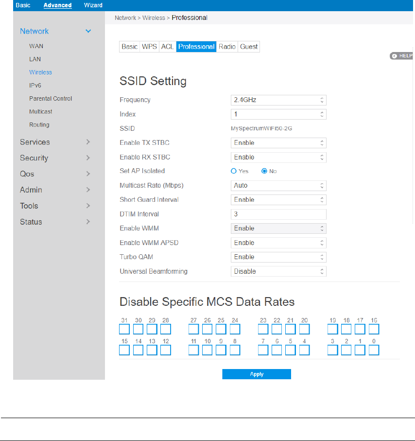
2.4.1.3.4 Professional
The Professional module provides advanced configuration options.
NOTE: We recommend that administrators use the default settings.
In this module, administrator can configure the followings:
1. From the navigation panel, go to Advanced > Network > Wireless >
Professional.

59
2. Frequency: Select the frequency band to configure professional settings.
3. Index: Indicates witch SSID is under setting.
4. SSID: A name whose length is less than 32 characters is used to identify a
wireless network.
5. Enable TX STBC: Enables or disables the Space Time Coding Block (STBC)
feature, as described in 802.11n specification, in transmitting (TX) direction.
6. Enable RX STBC: Enables or disables the Space Time Coding Block (STBC)
feature, as described in 802.11n specification, in receiving(RX) direction.
7. Set AP Isolated: Prevent wireless devices from communicating with each other
via router. This feature is useful if many guests frequently join or leave your
network. Select [Yes] to enable this feature or select [No] to disable.
8. Multicast Rate (Mbps): Setting transmission rate for multicast.
9. Short Guard Interval: Defines the length of time that the router spends for CRC
(Cyclic Redundancy Check). CRC is a method of detecting errors during data
transmission. Select Enable for a busy wireless network with high network
traffic.
10. DTIM Interval: DTIM (Delivery Traffic Indication Message) Interval or Data
Beacon Rate is the time interval before a signal is sent to a wireless device in
sleep mode indicating that a data packet is awaiting delivery. The default value is
three milliseconds.
11. Enable WMM: Enables or disables WMM capabilities in the driver. The WMM
capabilities perform special processing for multimedia stream data including
voice and video data.
12. Enable WMM APSD: Enable WMM APSD (Wi-Fi Multimedia Automatic
Power Save Delivery) to improve power management between wireless devices.
Select Disable to switch off WMM APSD.
13. Turbo QAM: 256-QAM (MCS 8/9) support. Wireless Mode must be set to auto.
14. Universal Beamforming: For legacy wireless network adapters which do not
support beamforming, the router estimates the channel and determines the
steering direction to improve the downlink speed. (Also known as Implicit
60
Beamforming.)
15. Click Apply.
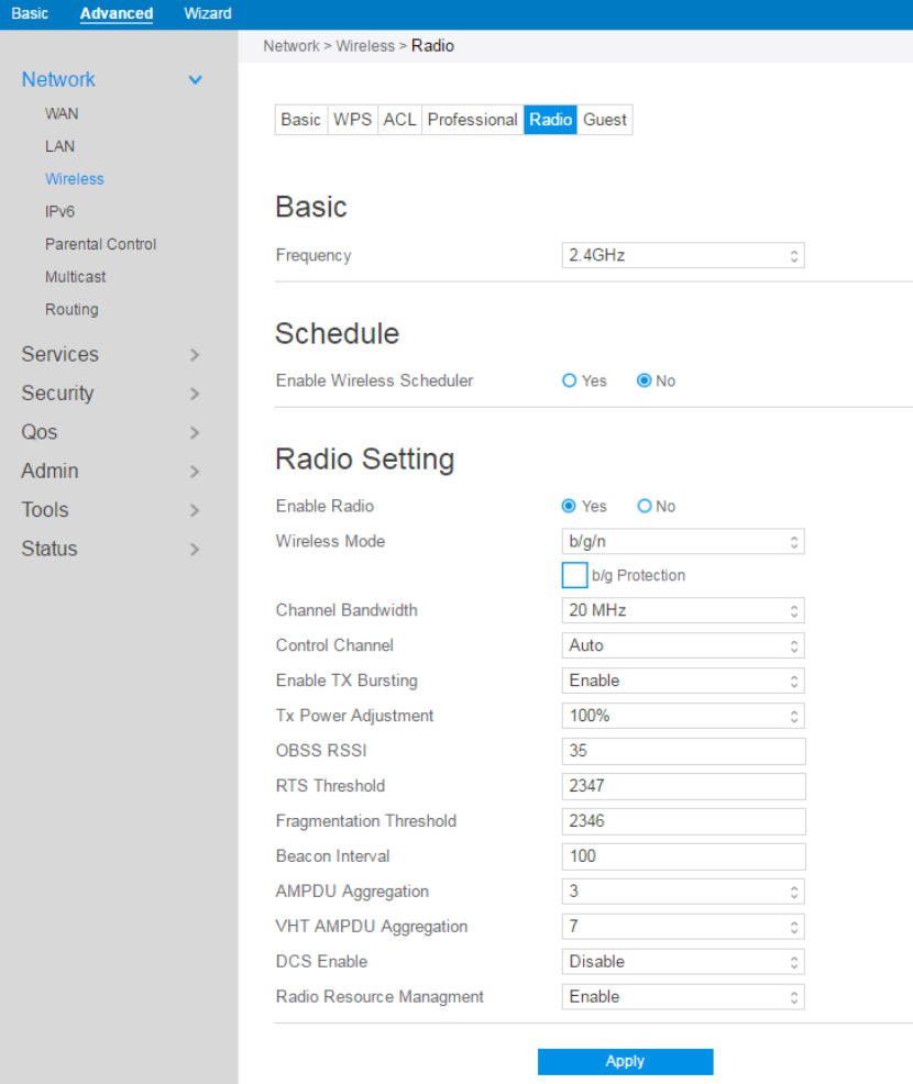
2.4.1.3.5 Radio
Administrator can set some advanced feature for radio of the router.
Steps to set Radio:
1. From the navigation panel, go to Advanced > Network > Wireless > Radio.

61
2. Frequency: Selecting the frequency band that the router is running.
3. Enable Wireless Scheduler: Switch wireless schedule on or not.
4. Date to Enable (Weekdays): Select weekdays to enable Wi-Fi.
5. Time of Day To Enable: Set weekday time to enable Wi-Fi.
6. Date to Enable (Weekend): Select weekend days to enable Wi-Fi.
7. Time of Day To Enable: Set weekend time to enable Wi-Fi.
8. Enable Radio: Select [Yes] to enable wireless radio (wireless network). Select
[No] to disable wireless radio (wireless network).
9. Wireless Mode: Select a Wireless Mode of your 802.11n interface.
10. Channel Bandwidth: Sets manual channel bandwidth.
11. Control Channel: The radio channel for wireless connection operation.
12. Enable TX Bursting: TX Bursting improves transmission speed between router
and 802.11g devices.
13. Tx Power Adjustment: Set the capability for transmission power. The maximum
value is 100%. You can save power and increase security if you don’t require full
wireless range.
NOTE: Increasing the Transmission Power adjustment values may affect the stability
of the wireless network.
14. OBSS RSSI: Configure OBSS RSSI threshold. If OBSS RSSI is greater than
configured value, then only move to 20 Mhz.
15. RTS Threshold: Select a lower value for RTS (Request to Send) Threshold to
improve wireless communication in a busy or noisy wireless network with high
network traffic and numerous wireless devices.
16. Fragmentation Threshold: Set the fragmentation threshold, which is the
maximum fragment size.
17. Beacon Interval: Beacon Interval means the period of time between one beacon
and the next one. The default value is 100 (the unit is millisecond, or 1/1000
62
second). Lower the Beacon Interval to improve transmission performance in
unstable environment or for roaming clients, but it will be power consuming.
18. AMPDU Aggregation: Enables or disables Tx AMPDU aggregation for the
entire interface. Receiving aggregate frames will still be performed, but no
aggregate frames will be transmitted if this is disabled.
19. VHT AMPDU Aggregation: Set VHT capability field, Maximum A-MPDU
length exponent. Value range is 0 to 7. Maximum A-MPDU length exponent
indicates the maximum length of A-MPDU that the station can receive.
20. DCS Enable: Enable or disable DCS function which is a feature to detect and
avoid CW interference.
21. Radio Resource Management: Enables or disables 802.11k
22. When done, click Apply
2.4.1.3.5 Guest
The Guest network can temporarily provide 2.4GHz and 5GHz network connections.
Guests can connect to your specific network name (SSID) and won't connect to your
private network.
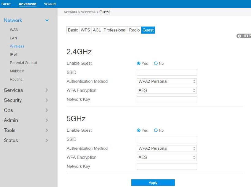
63
Steps to set Guest module:
1. From the navigation panel, go to Advanced > Network > Wireless > Guest.
2. Enable Guest: Enable/disable the guest SSID.
3. SSID: Name of the Guest wireless network.
4. Authentication Method: Choose way to exchange authentication data.
5. WPA Encryption: Choose the encrypting method.
6. Network Key: Key used to encrypt the authentication data.
7. When done, click Apply.
64
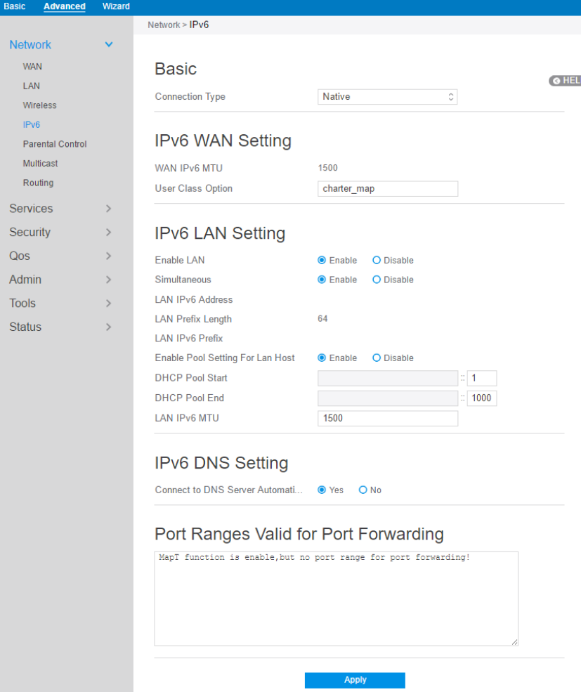
2.4.1.4 IPv6
The module is used to set some basic functions related to IPv6. For IPv6 service is not
yet widely available, contact your ISP to make sure whether IPv6 service is provided.
Steps to set up IPv6:
1. From the navigation panel, go to Advanced > Network > IPv6.
65
2. Connection Type: Select IPv6 connection type to configure Disable, Native,
Static IPv6.
3. DHCP-PD: Dhcpv6 prefix delegation.
4. WAN IPv6 Address: Set the wan interface’s ipv6 address.
5. WAN Prefix Length: Set the wan interface’s ipv6 prefix length.
6. WAN IPv6 Gateway: Set the wan interface’s ipv6 gateway
7. WAN IPv6 MTU: Set the WAN interface’s IPv6 MTU (Maximum Transmission
Unit).
8. User Class Option: The user class option (15) of ORO that DHCPv6 clients send
to the DHCPv6 server by solicit message.
9. Auto Configuration: The wan interface’s address assign type (SLAAC). Enable:
WAN interface can get ipv6 address by SLAAC. Disable: WAN interface gets the
ipv6 address only by stateful.
10. Enable LAN: Enable/Disable router allocating IPv6 addresses for lan-side
devices.
11. Simultaneous: The mode which hosts connected to the LAN interface can get
IPv6 addresses. When enabled, hosts get IPv6 address by simultaneous Stateless
and/or Stateful (requires DHCP pool start and end values). When disabled, hosts
do not get IPv6 addresses simultaneously by Stateless and/or Stateful, and a mode
must be selected instead.
12. LAN IPv6 Address: Set LAN interface’s IPv6 address.
13. LAN Prefix Length: Set LAN interface’s IPv6 prefix length.
14. LAN IPv6 Prefix: Set LAN interface’s prefix.
15. Enable Pool Setting For Lan Host: Enable/Disable allocating ranged IPv6
addresses for lan-side devices.
16. DHCP Pool Start: DHCPv6 address setting address pool start.
17. DHCP Pool End: DHCPv6 address setting address pool end.
18. PD-Valid Lifetime: Prefix delegation for valid lifetime.
19. PD-Preferred Lifetime: Prefix delegation for preferred lifetime.
20. LAN IPv6 MTU: Set MTU for lan-side devices.
21. Connect to DNS Server Automatically: Choose to get the DNS from manually
from uplink.

66
22. IPv6 DNS Server 1: IPv6 address for DNS server.
23. IPv6 DNS Server 2: IPv6 address for DNS server.
24. IPv6 DNS Server 3: IPv6 address for DNS server.
25. Port Ranges Valid for Port Forwarding: The "port ranges" are set by Map-T
mode, and the port setting for port forwarding must be in these ranges.
26. Click Apply.
67
2.4.1.7 Parental Control
Refer to 2.3.5 Parental Control for relevant setting descriptions.
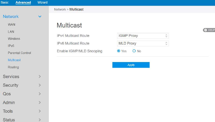
2.4.1.8 Multicast
Enable multicast. The sender and receiver achieve a point to multipoint connection.
Steps to set up Multicast:
1. From the navigation panel, go to Advanced > Network > Multicast.
2. IPv4 Multicast Route: Select an IPv4 Multicast Route.
*IGMP Proxy: IGMP Proxy enables hosts in a unidirectional link routing (UDLR)
environment that are not directly connected to a downstream router to join a
multicast group sourced from an upstream network.
*PIM: PIM-Source-specific multicast (SSM) is used in IPv4/IPv6 and is a method
of delivering multicast packets in which the only packets that are delivered to a
receiver are those originating from a specific source address requested by the
receiver. By limiting the source, SSM reduces demands on the network and
improves security.
68
3. IPv6 Multicast Route: Select an IPv6 Multicast Route.
*MLD Proxy: The MLD proxy is used in IPv6 environments. This feature enables
a device to learn proxy group membership information, and forward multicast
packets based upon that information. If a device is acting as RP for route proxy
entries, MLD membership reports for these entries can be generated on user
specified proxy interface.
4. Enable IGMP/MLD Snooping: Check [Yes] to enable snooping and Check [No]
to disable snooping. IGMP/MLD snooping is the process of listening to Internet
Group Management Protocol (IGMP) / Multicast Listener Discovery (MLD)
network traffic. The feature allows a network switch to listen in on the
IGMP/MLD conversation between hosts and routers. By listening to these
conversations the switch maintains a map of which links need which IP multicast
streams. Multicasts may be filtered from the links which do not need them and
thus controls which ports receive specific multicast traffic.
5. When done, click Apply.
69
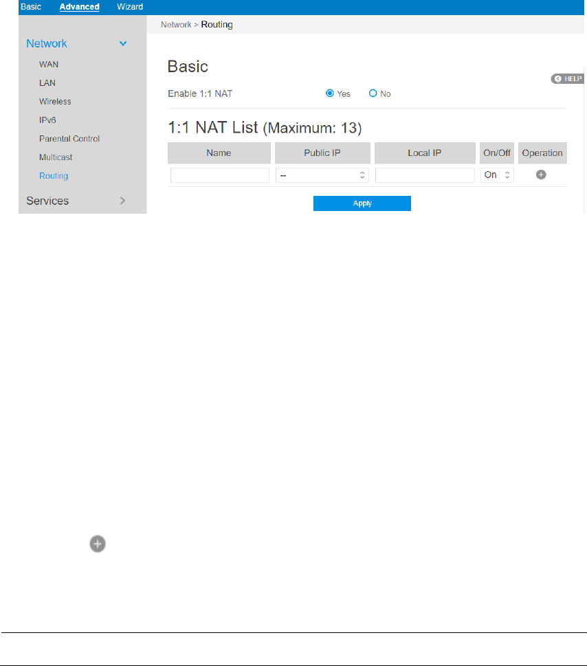
2.4.1.9 Routing
This module can be used to build a static NAT table between WAN IP address and
LAN IP address.
Steps to set up Routing:
1. From the navigation panel, go to Advanced > Network > Routing.
2. Enable 1:1 NAT: Check [Yes] to enable this function, check [No] to disable this
function.
3. Name: A brief description for application.
4. Public IP: IP address from Charter supplied public IP subnets.
5. Local IP: Key in the client’s LAN IP address, not limited to the subnet
for the
directly connected LAN interface
6. Click On/Off to enable/disable Internet access to FTP service.
7. Click to add this item to the 1:1 NAT List.
8. Click Apply.
NOTE: This module only works only when WAN port is in static mode!
70
2.4.2 Services
2.4.2.1 USB Printer sharing
Refer to 2.3.6.1 USB Printer sharing for relevant setting descriptions.
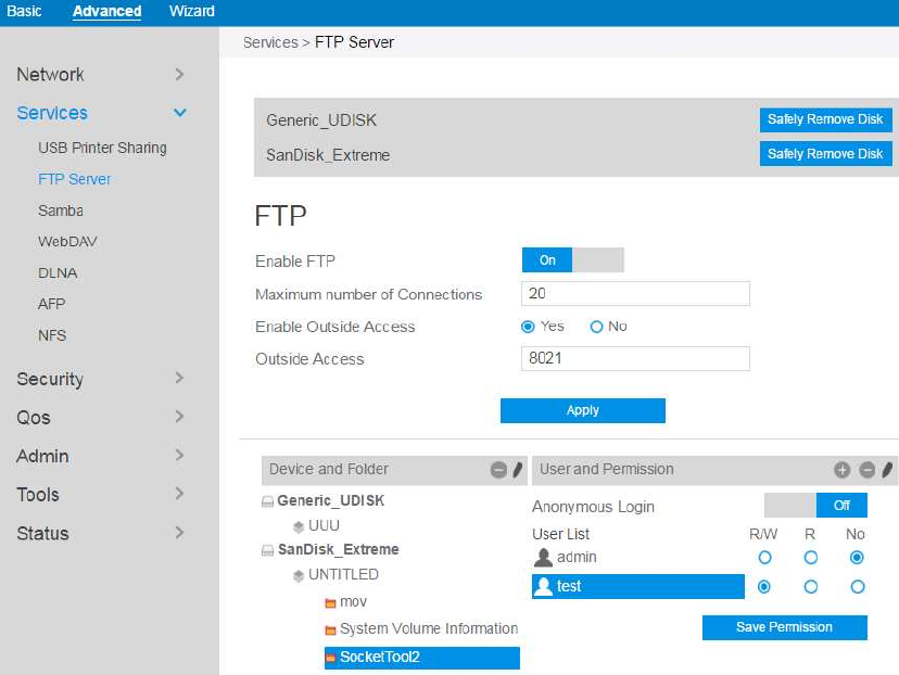
2.4.2.2 FTP Server
FTP Server enables an FTP server to share files from USB disk to other devices via
your local area network or via the Internet.
To set up FTP Server:
9. From the navigation panel, go to Advanced > Services > FTP Server.
10. Connect an external USB hard disk drive or USB flash drive to the router, and
your device will be displayed here.
11. Click On/Off to enable/disable Internet access to FTP service.
71
To create a new account:
1. Add new account.
2. In the Account and Password fields, key in the name and password of your
network client. Retype the password to confirm. Click Add to add the
account to the list.
To add a folder:
1. Add new folder.
2. Enter a folder name. The folder that you created will be added to the folder
list.
To set up permissions on the folder for FTP server:
1. From the list of folders, choose one of the shared folders and select the type
of access permission that you want to assign for specific users:
R/W: Select this option to assign read/write access.
R: Select this option to assign read-only access.
No: Select this option if you do not want to share a specific file folder.
2. Click Save Permission to apply the changes.
Refer to the following descriptions:
Maximum number of Connections: The maximum number of concurrent
connections for the Network Neighborhood or FTP Server.
Enable Outside Access: Select On/Off to enable/disable to access FTP
server by wide area network.
Outside Access: The numbers of external service ports (default value: 8021).
Anonymous Login: Enable/disable anonymous access to the FTP server.
Safely Remove Disk: Click to safely remove disk. When the USB disk is
ejected successfully, the USB status shows “No device”.
Click Save Permission.
72
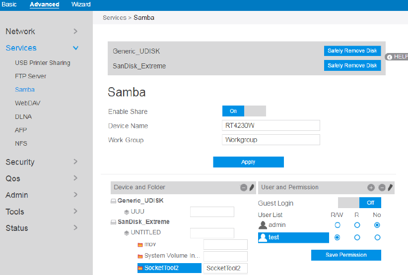
2.4.2.3 Samba
Samba Share allows you to set up the accounts and permissions for the Samba
service.
To set up Samba:
1. From the navigation panel, go to Advanced > Services > Samba Server.
2. Connect an external USB hard disk drive or USB flash drive to the router,
and your device will be displayed here.
3. Click On/Off to enable/disable Internet access to Samba service.
To create a new account:
1. Add new account.
2. In the Account and Password fields, key in the name and password of your
network client. Retype the password to confirm. Click Add to add the
account to the list.
To add a folder:
73
1. Add new folder.
2. Enter a folder name. The folder that you created will be added to the folder
list.
To set up permissions on the folder for Samba server:
1. From the list of folders, choose one of the shared folders and add the share
name, and choose the type of access permission that you want to assign for
specific users:
R/W: Select this option to assign read/write access.
R: Select this option to assign read-only access.
No: Select this option if you do not want to share a specific file folder.
2. Click Save Permission to apply the changes.
Refer to the following descriptions:
Device Name: Enter a name for your device and you can use this name in your
web browser's URL field to quickly access the device as a Network Place
service.
Work Group: Group name of the cascade in Network Neighborhood.
Note: The standard input characters include letters (A-Z, a-z), digits (0-9). The
hyphen (-) and under line (_) characters may also be used, but not as the first
character.
Guest Login: By enabling [Guest Login], any user in your local network can
access your network place (Samba) without authentication.
Safely Remove Disk: Click to safely remove the disk. When the USB disk is
ejected successfully, the USB status shows 'No device '.
Click Save Permission.
74
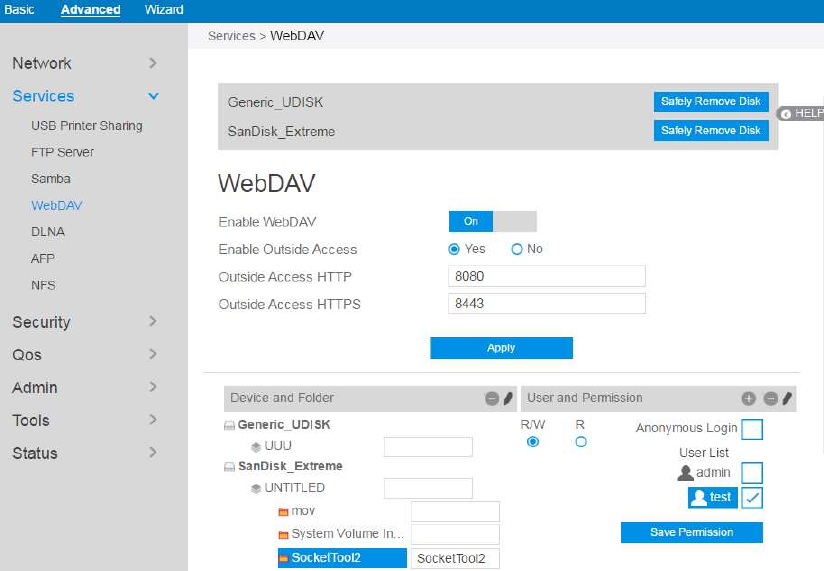
2.4.2.4 WebDAV
The client can write operation in WebDAV directory with appropriate permissions.
To set up WebDAV:
1. From the navigation panel, go to Advanced > Services > WebDAV Server.
2. Connect an external USB hard disk drive or USB flash drive to your router,
and your device will be displayed here.
3. Click On/Off to enable/disable Internet access via WebDAV.
To create a new account:
1. Add new account.
2. In the Account and Password fields, key in the name and password of your
network client. Retype the password to confirm. Click Add to add the
account to the list.
To add a folder:
75
1. Add new folder.
2. Enter a folder name. The folder that you created will be added to the folder
list.
To set up permissions on the folder for WebDAV server:
1. From the list of folders, choose one of the shared folders and add the share
name, then choose the type of access permission that you want to assign for
specific users:
R/W: Select this option to assign read/write access.
R: Select this option to assign read-only access.
2. Click Save Permission to apply the changes.
Refer to the following for the descriptions of the fields:
Enable Outside Access: Select On/Off to enable/ disable access to WebDAV
server by WAN (wide area network).
Outside Access: The port number of external service ports via HTTP (default
value: 8080).
Outside Access HTTPS: The port number of external service ports via
HTTPS (default value: 8443).
Safely Remove Disk: Click to safely remove the disk. When the USB disk is
ejected successfully, the USB status shows 'No device '.
Click Save Permission.
76
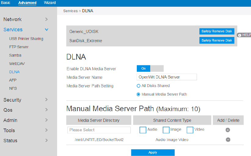
2.4.2.5 DLNA
DLNA (Digital Living Network Alliance) allows you to share audio, image and video.
Your router allows DLNA-supported devices to access multimedia files from the USB
disk connected to your router.
To set up DLNA:
1. From the navigation panel, go to Advanced > Services > DLNA Server.
2. Enable DLNA Media Server: Switch DLNA media on or off.
3. Media Server Name: The DLNA server's name, which will be displayed by
the media player, such as VLC or windows media player.
4. Media Server Path Setting: The methods of setting the folders' path which
will be shared. There are two methods to be chose, "All Disks Shared" means
share all of the mounted disks' all media; "Manual Media Server Path"
means set the folders to be shared manually, When Manual is selected you
must enter additional information in " Manual Media Server Path".
5. Manual Media Server Path: Set the folders to be shared and the media type

77
that will be shared by the DLNA server.
6. Media Server Directory: The folders that will be shared by the DLNA.
7. Shared Content Type: The media type that will be shared by the DLNA
server: audio, image, video.
8. Safely Remove Disk: Click to safely remove the disk. When the USB disk is
ejected successfully, the USB status shows 'No device '.
9. Click Apply.
2.4.2.6 AFP
An AFP server is a kind of network file sharing server based on AFP protocol
implementation, mainly used for file sharing between Linux and MAC systems.
To set up AFP:
1. From the navigation panel, go to Advanced > Services > AFP Server.
2. Connect an external USB hard disk drive or USB flash drive to your router,
and your device will be displayed here.
3. Click the On/Off to enable/disable Internet access via AFP.
To create a new account:
78
1. Add new account.
2. In the Account and Password fields, key in the name and password of your
network client. Retype the password to confirm. Click Add to add the
account to the list.
To add a folder:
1. Add new folder.
2. Enter a folder name. The folder that you created will be added to the folder
list.
To set up permissions on the folder for AFP server:
1. From the list of folders, choose one of the shared folder and add the share
name, and choose the type of access permission that you want to assign for
specific users:
RW: Select this option to assign read/write access.
R: Select this option to assign read-only access.
No: Select this option if you do not want to share a specific file
folder.
2. Click Save Permission to apply the changes.
Refer to the following for the descriptions of the fields:
Guest Login: By enabling [Guest Login], any user in your local network
can access your network place (AFP) without authentication.
Safely Remove Disk: Click to safely remove the disk. When the USB disk is
ejected successfully, the USB status shows 'No device '.
Click Save Permission.
79
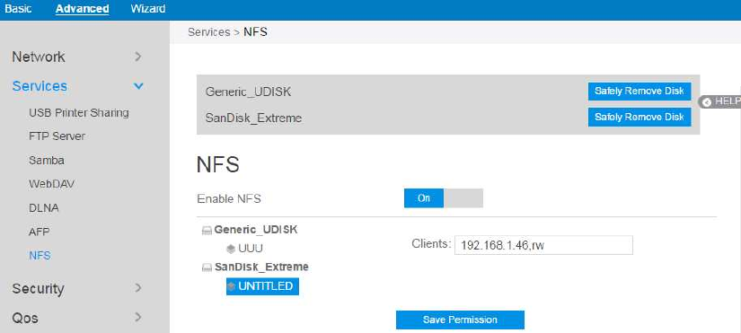
2.4.2.7 NFS
Network File System Server is used to share the USB disk with clients via network.
Clients can mount the remote disk to a local directory for a faster speed than using a
Samba server.
To setup NFS:
1. From the navigation panel, go to Advanced > Services > NFS Server.
2. Connect an external USB hard disk drive or USB flash drive to your router,
and your device will be displayed here.
3. Enable NFS: Enable or disable NFS service. When disabled, users can't
access the USB storage via the NFS service.
4. Clients: "Clients" are users who can access the shared partition specified.
You can input the proper information into the input field to allow the clients
to access the specified shared partition. The proper permission format is "IP
address, Read and write permission" and if you want to set more than one
clients and with different permission, you can input the information separated
by ";". For read and write permissions, "ro" means "read only" permission
and the "rw" means " read and write" permission. The IP address can be
replaced by "*" and means all IPs. For example,
1) Allows the clients with the IP address 192.168.1.2 to access the partition
80
with "read and write" permission.
2) Allows two clients to access the shared partition. The client with IP
address 192.168.1.2 has "read only" permission, and the client with IP
address 192.168.1.3 has "read and write" permission. >
192.168.1.2,ro;192.168.1.3,rw
3) Allows all clients to access the destination shared partition with the "read
only" permission. > *,ro
5. Safely Remove Disk: Click to safely remove the disk. When the USB disk is
ejected successfully, the USB status shows 'No device '.
2.4.3 Security
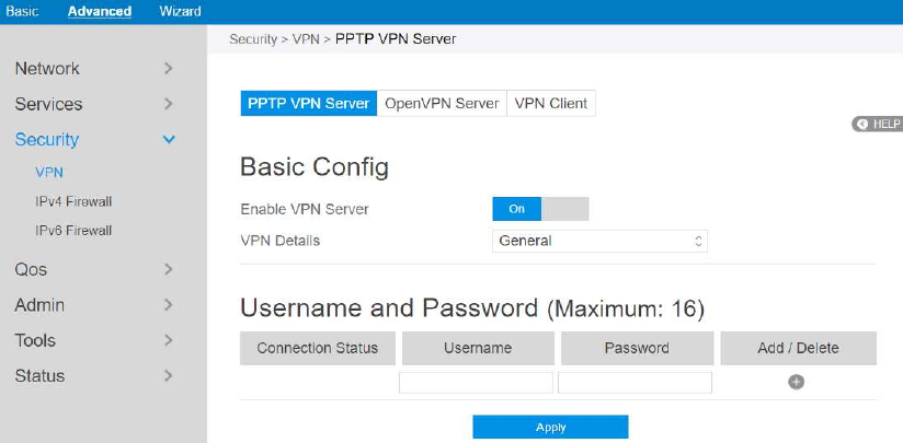
2.4.3.1 VPN
VPN (Virtual Private Network) provides a secure communication to a remote
computer or remote network using a public network such as the Internet.
2.4.3.1.1 PPTP VPN Server
The VPN server allows administrator to get access to home network anytime,
anywhere.
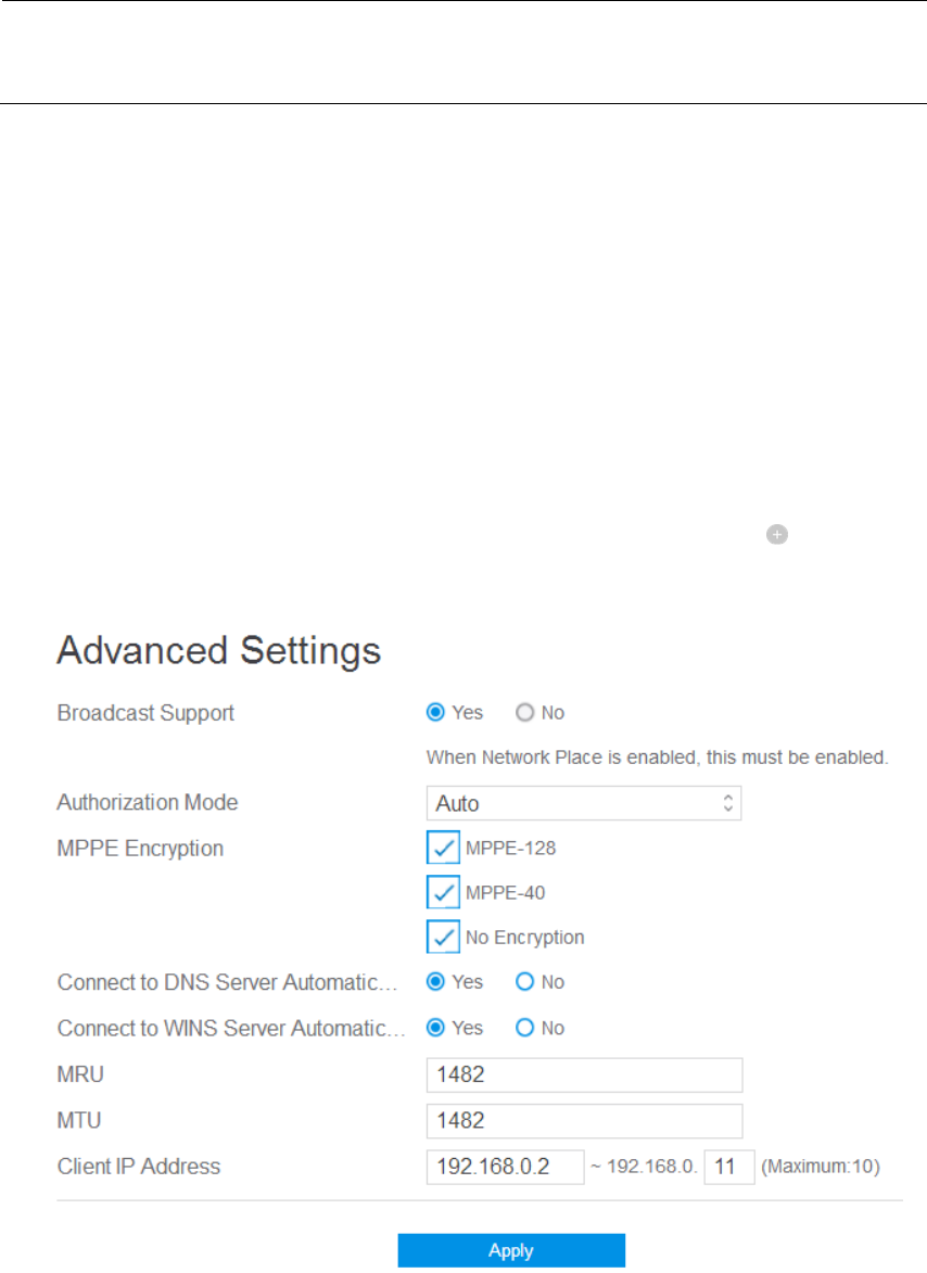
81
NOTE: Before setting up a VPN connection, you need the IP address or domain name
of the VPN server you are trying to access.
Steps to set up access to PPTP VPN server:
1. From the navigation panel, go to Advanced > Security > VPN > PPTP VPN
Server.
Enable VPN Server: enable or disable PPTP VPN Server.
VPN Details: The details of PPTP VPN Server. Select General or Advanced
settings.
Username and Password: The user information of PPTP VPN Server. Input
the user name and password for the VPN server and click the button.
2. Advanced VPN server settings, as below.
Broadcast Support: Turns on broadcast relay to clients from the router.
Authorization Mode: Select Authorization Mode.
MPPE Encryption: Select MPPE Encryption type.
Connect to DNS Server Automatically: DNS of PPTP clients.
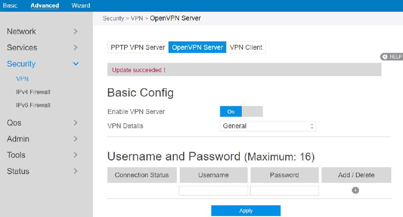
82
Connect to WINS Server Automatically: WINS of PPTP clients.
MRU/MTU: The Maximum Receive Unit (MRU) or Maximum
Transmission Unit (MTU) sizes are sent to the client as part of the PPTP
parameters to use during the PPTP session. We recommend that you do not
change MTU or MRU values unless you are sure the change corrects a
known problem with your PPTP sessions. Incorrect MTU or MRU values
cause traffic through the PPTP VPN to fail.
Client IP Address: The IP address range of PPTP clients.
Click Apply.
2.4.3.1.2 OpenVPN Server
The VPN server allows administrator to get access to home network anytime,
anywhere.
Steps to set OpenVPN Server:
1. From the navigation panel, go to Advanced > Security > VPN > OpenVPN
Server.
Enable VPN Server: Enable or disable OpenVPN server function.
VPN Details: Enter the details of your VPN server. Select General or
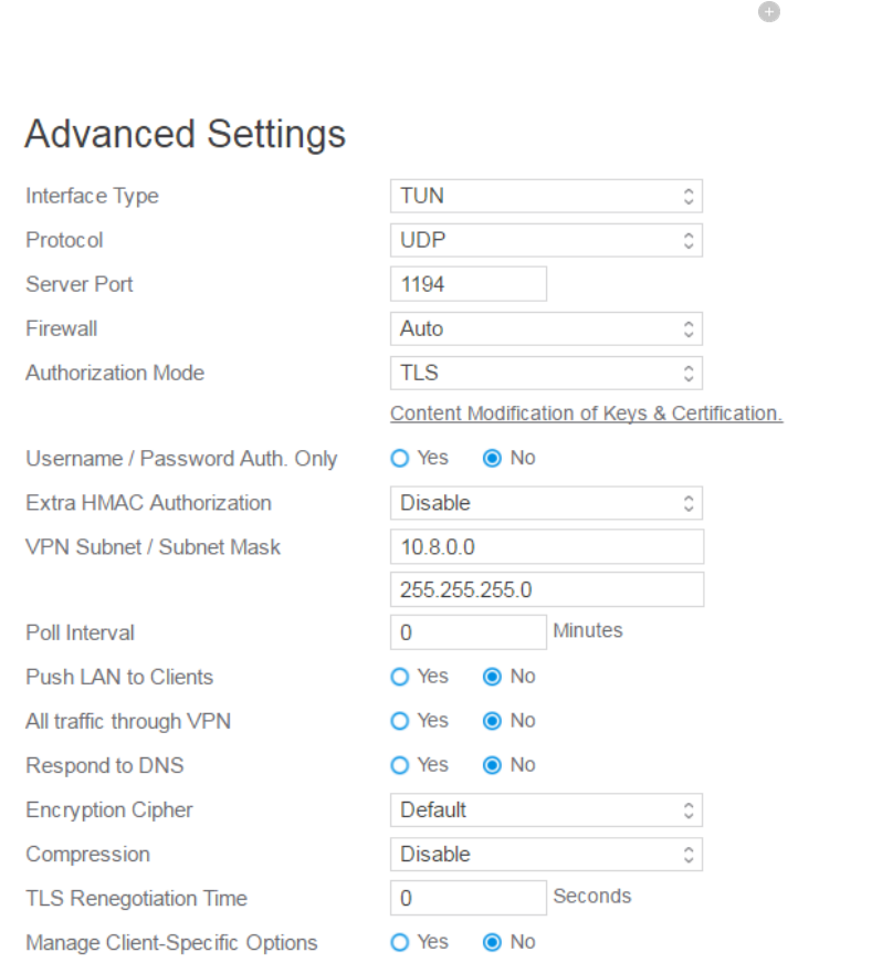
83
Advanced settings.
Username and Password: The user information of OpenVPN server. Input
the user name and password for the VPN server and click the button.
2. Advanced VPN server settings:
Interface Type: "TUN" will create a routed IP tunnel, "TAP" will create an
Ethernet tunnel.
Protocol: TCP or UDP server.
Server Port: The TCP/UDP port which OpenVPN server will listen on.
Firewall: Firewall configuration for VPN server. Auto will create complete
firewall configurations, External only will create basic firewall
configurations and Custom will not create any firewall configurations.
Authorization Mode: Select Authorization Mode.
84
Username / Password Auth. Only: Yes requires only username and
password for authentication, No also requires authentication certificate.
Extra HMAC Authorization: If enabled, a tls_auth key will be used on the
server. Every client must also have the key.
VPN Subnet / Subnet Mask: VPN subnet and subnet mask settings.
Poll Interval: The interval time for crontab of VPN server starting.
Push LAN to Clients: Push routes to the client to allow it to reach other
private subnets behind the server.
All traffic through VPN: If enabled, this directive will configure all clients
to redirect their default network gateway through the VPN, causing all IP
traffic such as web browsing and DNS lookups to go through the VPN.
Respond to DNS: Push DNS to clients.
Encryption Cipher: Select a cryptographic method. This configure item
must be copied to the client configure file as well.
Compression: Enable compression on the VPN link. If this function is
enable here, in the client configure administrator also should enable it.
TLS Renegotiation Time: After a period of time, authentication is required
again.
Manage Client-Specific Options: To assign specific IP addresses to specific
clients or if a connecting client has a private subnet behind it that should also
have VPN access, enable this option.
Click Apply.
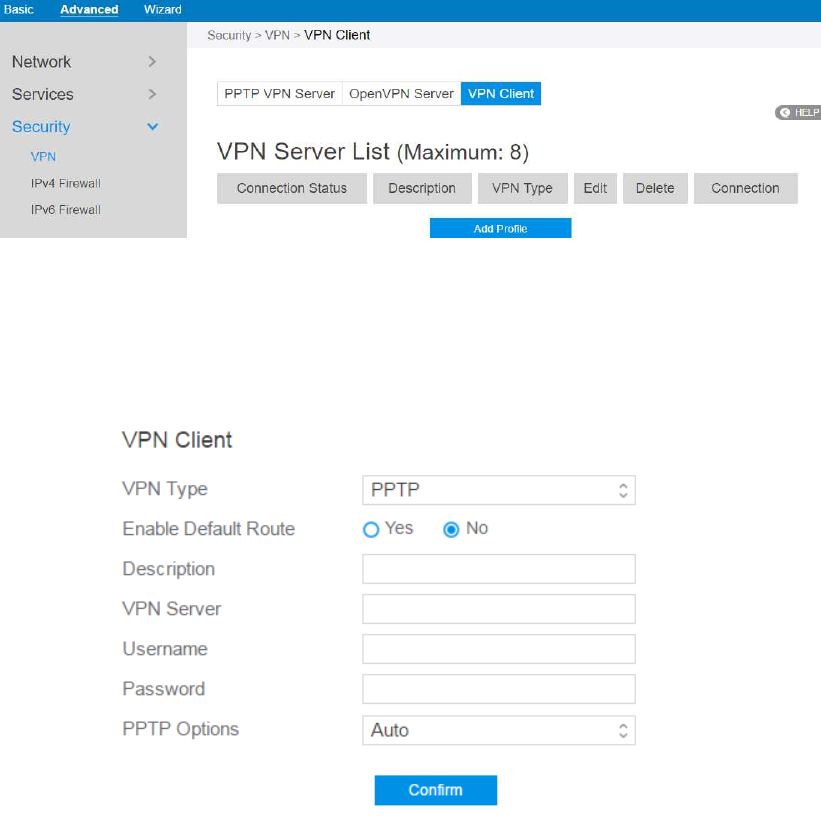
85
2.4.3.1.3 VPN Client
View the VPN server list and add profiles. There are three types of VPN servers:
PPTP, L2TP and OpenVPN.
Steps to setup a VPN Client:
1. From the navigation panel, go to Advanced > Security > VPN > VPN Client.
2. VPN Sever list is displayed. Click Add Profile to set up VPN Client.
3. VPN Server List: Current VPN Services which have been configured.
4. VPN Type: Type of VPN Server access such as PPTP, L2TP and OpenVPN.
5. Enable Default Route: Check [Yes] to use default route acquiring from VPN
Server. Check [No] to use general default route.
6. Description: Enter a description for reference.
86
7. VPN Server: VPN Server IP address or URL.
8. Username: VPN authentication username.
9. Password: VPN authentication password.
10. PPTP Options: PPTP Encryption method. Select Auto for automatic Microsoft
Point-to-Point Encryption (MPPE) and select No Encryption to disable MPPE.
Select MPPE 40 for 40-bit MPPE with PPTP Server and select MPPE 128 for
128-bit MPPE with PPTP Server.
11. When done, click Confirm.
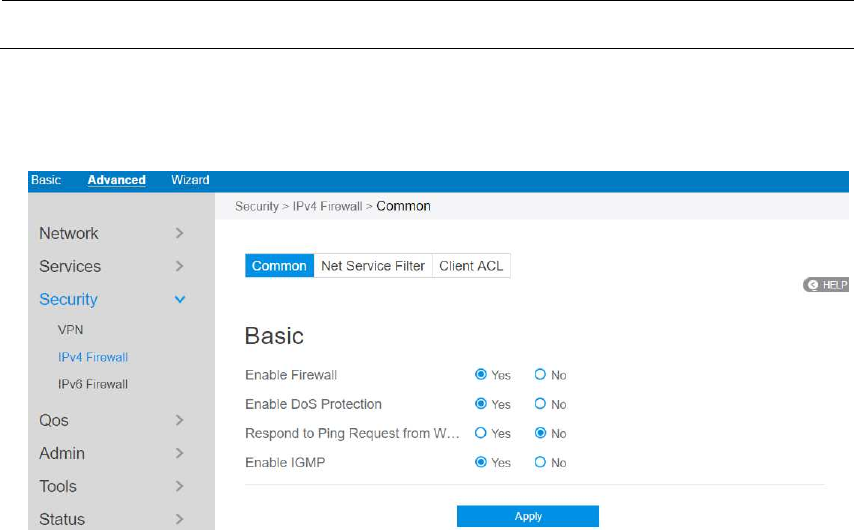
87
2.4.3.2 IPv4 Firewall
Enable the firewall to protect local area network against attacks from outside. Firewall
filters the incoming and outgoing packets based on rules.
NOTE: Firewall is enable by default.
2.4.3.2.1 Common
Steps to set up basic Firewall settings:
1. From the navigation panel, go to Advanced > Security > IPv4 Firewall >
Common.
2. Enable Firewall: Disabling the firewall will deactivate all related functions.
3. Enable DoS Protection: A "denial-of-service" attack is an explicit attempt to
deny legitimate users from using a service or computer resource. Enabling this
feature can protect the router from DoS attack but it would increase the router's
workload.
4. Respond to Ping Request from WAN: This feature allows router to make a
response to ping request from WAN.
5. Enable IGMP: Check [Yes] to allow IGMP packages to be transferred to the
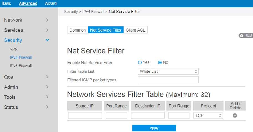
88
router. Check No to deny IGMP packages.
6. Click Apply.
2.4.3.2.2 Net Service Filter
Under the help of this module, administrator can set black list to block certain
services, or set white list to let some services to pass through the router.
Steps to set Net Service Filter 愪
1. From the navigation panel, go to Advanced> Security> IPv4 Firewall> Net
Service Filter.
2. Enable Net Service Filter: Enable or disable this module.
3. Filter Table List: There are two kinds of filter list: White List, Black List. White
List can make router serve the specified service defined in the list, Black List
make router deny serving the specified service.
4. Filtered ICMP packet types: This field defines a list of LAN to WAN ICMP
packets type that will be filtered. For example, if you would like to filter Echo
(type 8) and Echo Reply (type 0) ICMP packets, you need to enter a string with
numbers separated by blank, such as [0 8].
5. Source IP: For source or destination IP address, you can: (a) enter a specific IP

89
address such as "192.168.122.1"; (b) enter IP addresses within one subnet or
within the same IP pool such as "192.168.123.*" or "192.168.*.*"; or (c) enter all
IP addresses as "*.*.*.*".
6. Port Range: For source or destination port range, you can either: a) enter a
specific port, such as "95"; or b) enter ports within a range such as "103:315",
">100", or "<65535".
7. Destination IP: For source or destination IP address, you can: (a) enter a specific
IP address such as "192.168.122.1"; (b) enter IP addresses within one subnet or
within the same IP pool such as "192.168.123.*" or "192.168.*.*"; or (c) enter all
IP addresses as "*.*.*.*".
8. Port Range: For source or destination port range, you can either: a) enter a
specific port, such as "95"; or b) enter ports within a range, such as "103:315",
">100", or "<65535".
9. Protocol: The protocol of service used to transport the packages. (UDP, TCP)
10. Add/Delete: Click or to add/delete the profile.
11. When done, click Apply.
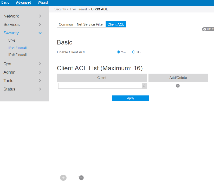
90
2.4.3.2.3 Client ACL
This module is used by administrator to prevent router from routing packets which are
from specified lan-side devices.
Steps to set up Client ACL 愪
1. From the navigation panel, go to Advanced> Security> IPv4 Firewall> Client
ACL.
2. Enable Client ACL: Enable or disable Client ACL function.
3. Client: MAC address of lan-side devices.
4. Add/Delete: Click or to add/delete the profile.
5. When done, click Apply.
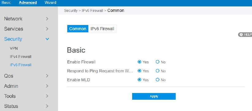
91
2.4.3.3 IPv6 Firewall
2.4.3.3.1 Common
Steps to set up common IPv6 Firewall:
1. From the navigation panel, go to Advanced > Security >IPv6 Firewall >
Common.
2. Enable Firewall: Disabling the firewall will deactivate all related functions.
3. Respond to Ping Request from WAN: This feature allows router to make a
response to ping request from WAN.
4. Enable MLD: Check [Yes] to allow MLD packages to be transferred to the router.
Check [No] to deny MLD packages.
5. Click Apply.
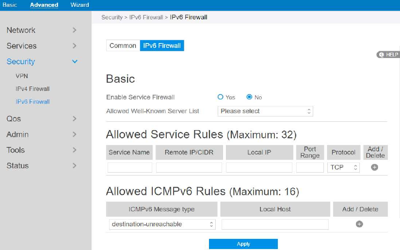
92
2.4.3.3.1 IPv6 Firewall
All outbound traffic coming from lan-side IPv6 hosts is allowed, as well as related
inbound traffic. Any other inbound traffic must be specifically allowed here. You can
leave the remote IP empty to allow traffic from any remote host. A subnet can also be
specified.
Steps to set up IPv6 Firewall:
1. From the navigation panel, go to Advanced > Security > IPv6 Firewall > IPv6
Firewall.
2. Enable Service Firewall: Enable or disable the IPv6 firewall. When disabled, all
IPv6 packages can input router, output router and forward without any limitation.
3. Allowed Well-Known Server List: List of well-known servers to be allowed.
For example: ftp, samba.
4. Service Name: The name of the service which will add IPv6 firewall rule.
5. Remote IP/CIDR: IPv6 address of a remote server.
6. Local IP: IPv6 address of a lan-side client.
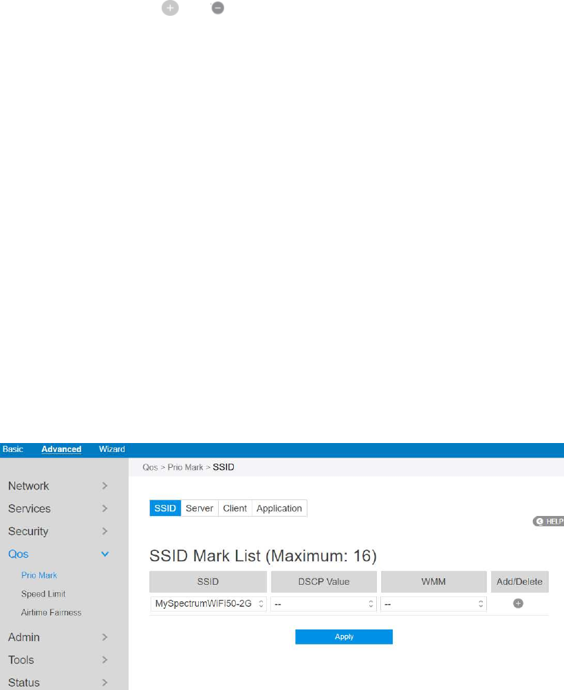
93
7. Port Range: Port range accepts various formats such as Port Range (300:350),
individual ports (566,789) or Mix (1015:1024, 3021).
8. Protocol: The protocol the service uses to transport the packages e.g. (UDP,
TCP).
9. ICMPv6 Message Type: Make router process the defined types of ICMPv6
packet from specified host.
10. Local Host: IPv6 address of the host.
11. Add/Delete: Click or to add/delete the profile.
12. When done, click Apply.
2.4.4 QoS
QoS(Quality of Service, QoS) module provides different services according to the
priority of applications, users, or data flows. In a word, it can guarantee a certain level
of performance to a data flow.
2.4.4.1 Prio Mark
2.4.4.1.1 SSID
This module can equip the router with the ability to provide QoS service to the
wireless connections.
Steps to set up:

94
1. From the navigation panel, go to QoS > Prio Mark > SSID.
2. SSID: Choose the name of t Wi-Fi which is going to provide QoS service.
3. DSCP Value: Its value is used to indicate the priority for uploading data.
4. WMM: Its value is used to indicate the priority for downloading data.
5. Click to add this item to the SSID Mark List.
6. Click Apply.
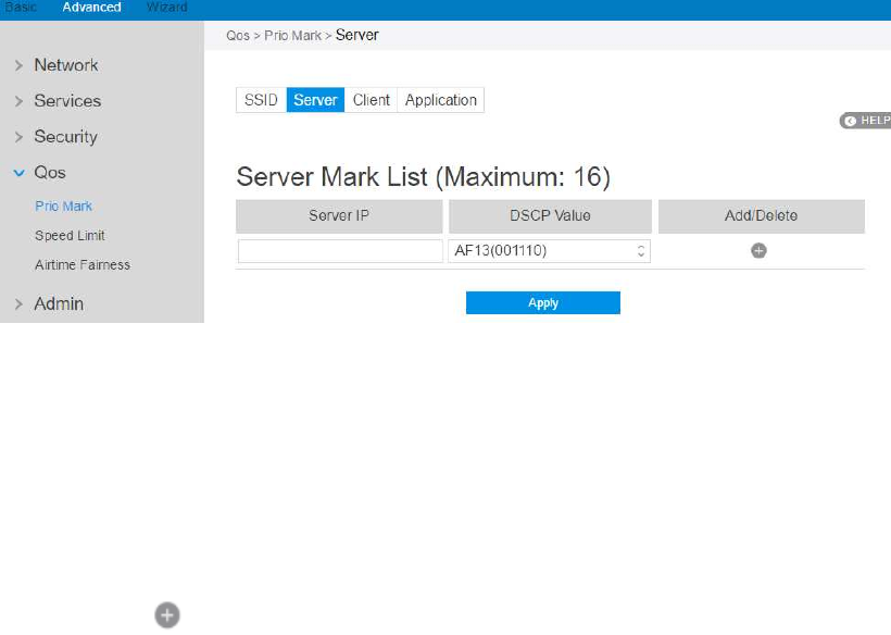
95
2.4.4.1.2 Server
For different remote servers, this setting can let the connections get different
priorities.
Steps to set up :
1. From the navigation panel, go to QoS > Prio Mark > Server.
2. Server IP: IP address of remote server.
3. DSCP Value: It’s value is used to indicate priority of connections to the
responding server.
4. Click to add this item to the Server Mark List.
5. Click Apply.
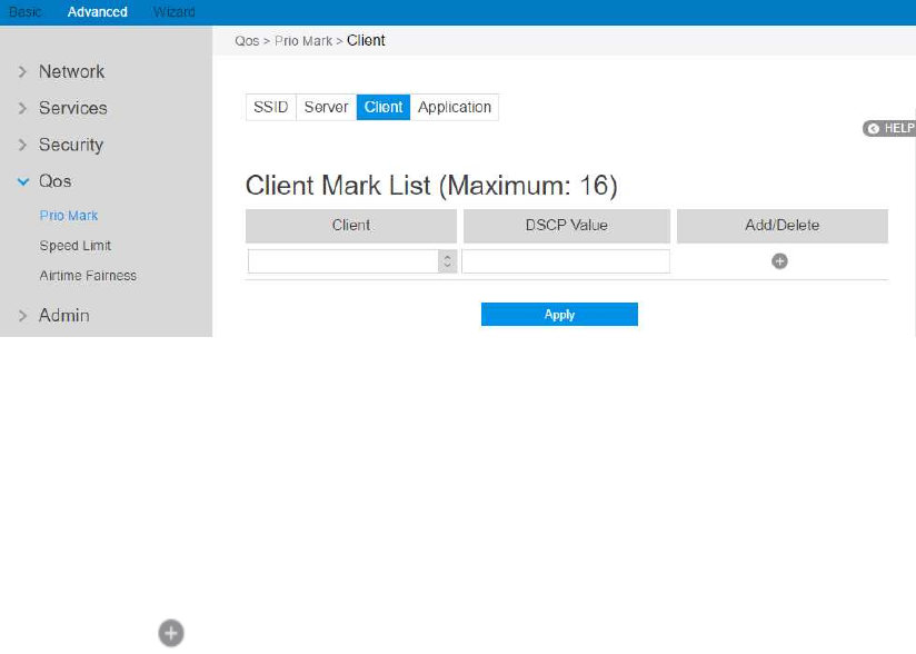
96
2.4.4.1.3 Client
Steps to set up :
1. From the navigation panel, go to QoS > Prio Mark > Client.
2. Client: MAC address of the lan side device.
3. DSCP Value: It’s value is used to indicate priority of connections to the
lan-side device.
4. Click to add this item to the Server Mark List.
5. Click Apply.
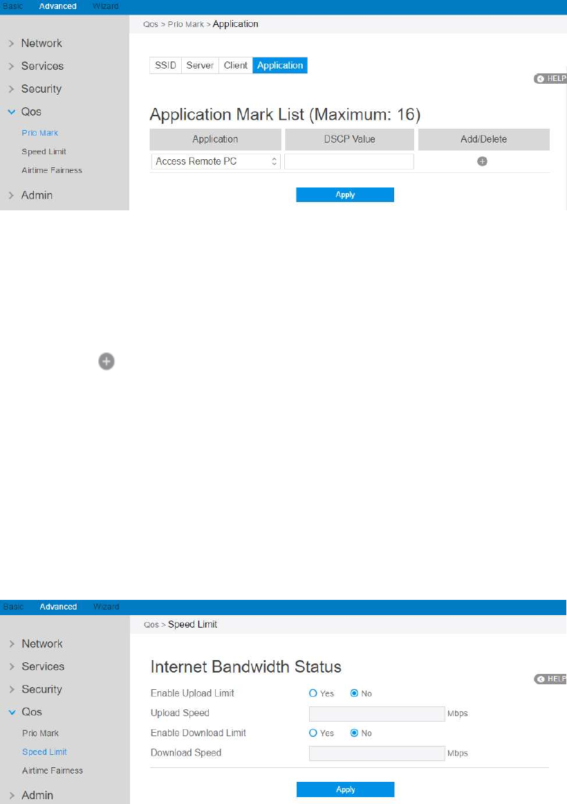
97
2.4.4.1.4 Application
Steps to set up :
1. From the navigation panel, go to QoS > Prio Mark > Application.
2. Application: The name of application that is going to use QoS.
3. DSCP Value: It’s value is used to indicate priority of application.
4. Click to add this item to the Server Mark List.
5. Click Apply.
2.4.4.2 Speed Limit
This module makes it possible for user to limit the speed of downloading and
uploading respectivly.
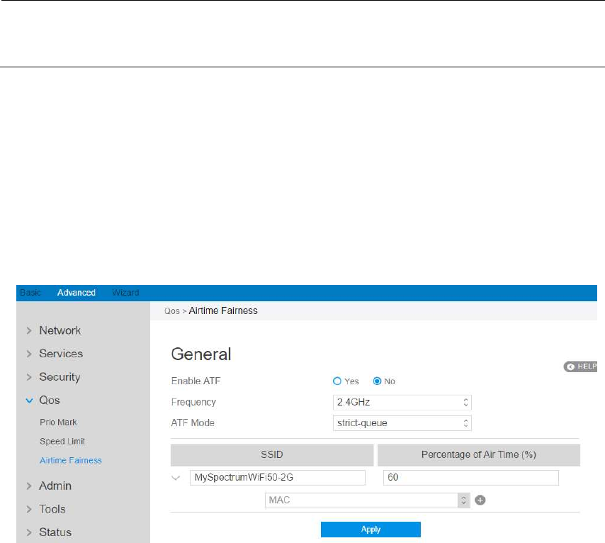
98
Steps to set up Speed Limit:
1. From the navigation panel, go to QoS > Speed Limit.
2. Enable Upload Limit: . Check [Yes] to enable upload speed limit and Check
[No] to disable upload speed limit.
3. Upload Speed: The highest speed that the router can provide for data
uploading.
4. Enable Download Limit: Choose the wifi that is going to provide QoS.
5. Download Speed: The highest speed that the router can provide for data
downloading.
6. Click Apply.
NOTE: If speed of uploading or downloading set by you is beyond actual value
provided by your ISP, your setting will take no effect
2.4.4.2 Airtime Fairness
The ATF(Airtime Fairness, ATF) module supports mixing rates of WiFi devices to
achieve better performance in busy/intense environments.
Steps to set ATF:
99
1. From the navigation panel, go to Advanced > QoS > Airtime Fairness.
2. Enable ATF: Enable or disable. ATF require primarily focuses on scheduling
fairness for transmission of traffic from Access Point (AP), and efficient Wi-Fi
bandwidth utilization.
3. Frequency: In the frequency field, select the frequency band that you want to use
for the ATF settings.
4. ATF mode: Airtime Fairness implements 2 scheduling algorithms: strict-queue
and fair-queue algorithm, which are mutually exclusive. Strict-queue algorithm
follows strict airtime allocation as configured by the user and does not try and
utilize any unused bandwidth. Fair-queue algorithm guarantees the configured
airtime in congested environments and it also utilizes any unused bandwidth.
5. SSID: Set the SSID which will be controlled by ATF.
6. Percentage of Air Time: Set the percentage of SSID which will be used for ATF
control.
7. MAC: Select client by MAC address and set the percent which will be used for
ATF control.
8. Click Apply
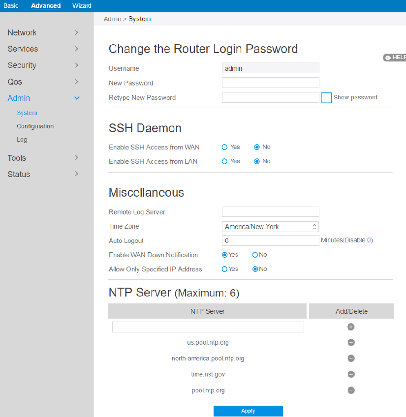
100
2.4.5 Admin
2.4.5.1 System
The System page allows you to configure your wireless router settings.
Steps to set System:
1. From the navigation panel, go to Advanced > Admin > System.
2. Username: Router’s login name.
3. New Password: New password.

101
4. Retype New Password: Retype new password.
5. Enable SSH Access from WAN: Enable or disable SSH connection from WAN
port.
6. Enable SSH Access from LAN: Enable or disable SSH connection from LAN
port.
NOTE: Three SSH accounts can be used to login the router.
1. Admin: username and password are: admin, admin
2. Operator: username and password are: operator, operator
3. Root: username and password are: root,
MmvGB^RY3#
MmvGB^RY3#MmvGB^RY3#
MmvGB^RY3#
7. Remote Log Server: IP address of a syslog server to which log messages will be
sent in addition to the local destination.
8. Time Zone: Default time-zone is America/ New York.
9. Enable Web Access from WAN: Enable or disable remote access via WAN port.
10. Auto Logout: Auto logout after a specified time.
11. Enable WAN Down Notification: When there is no Internet access, redirect to
local notification.
12. NTP Server: Router can access a NTP (Network Time Protocol) server in order
to synchronize the time automatically.
13. Click Apply.
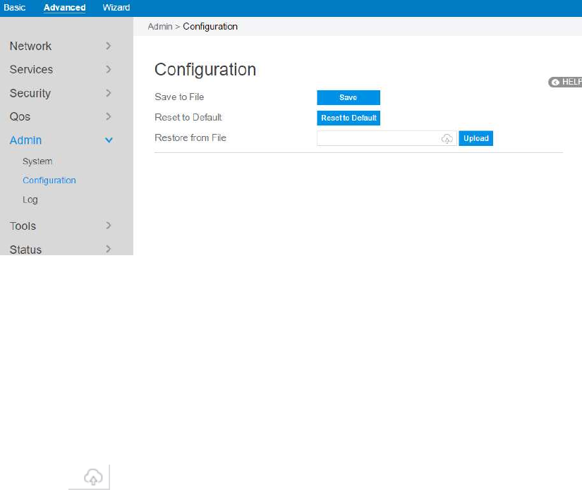
102
2.4.5.2 Configuration
Steps to save/reset/restore router’s configuration:
1. From the navigation panel, go to Advanced > Admin > Configuration.
2. Click Save, and then the browser will automatically download router’s setting
files.
3. Click Reset to Default, this will this resets all settings to factory default settings.
4. Click to select setting file, the click Upload button, this will make the
router to be set.
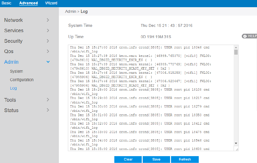
103
2.4.5.3 Log
System Log contains logs on network activities in the router.
Steps to set router’s log:
1. From the navigation panel, go to Advanced> Admin> Log.
2. Clear: Clear contents in log file.
3. Save: Download log file from router.
4. Refresh: Refresh the log window to show the latest log.
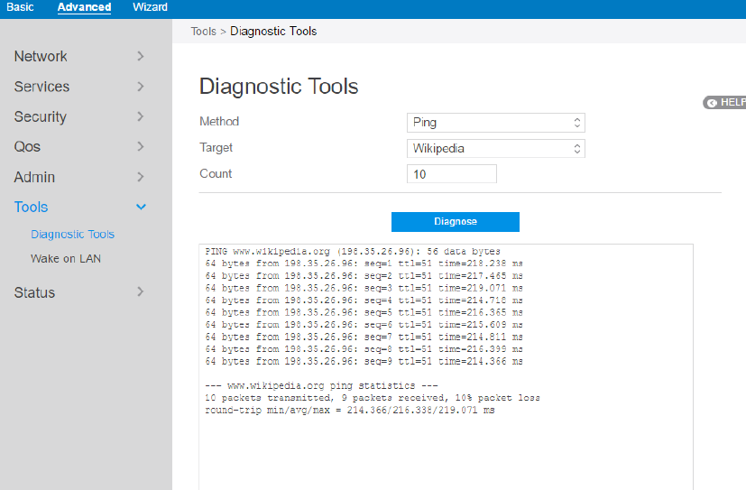
104
2.4.6 Tools
2.4.6.1 Diagnostic Tools
Various diagnostic tools are available such as ping, ping6, traceroute and nslookup.
Steps to use Diagnostic Tools:
1. From the navigation panel, go to Advanced> Tools> Diagnostic Tools
2. Method: Choose a specified method to test network.
3. Target: Choose target for the test.
4. Count: Number of times to test.
5. Click Diagnose.
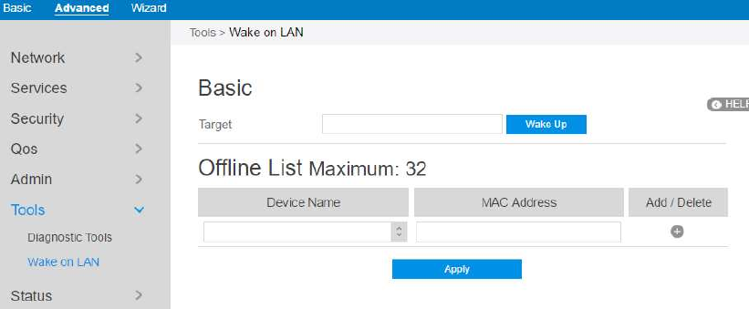
105
2.4.6.2 Wake on LAN
Wake on LAN is a power management function. It allows network admins to wake up
LAN side devices from standby or hibernation mode. This function requires
motherboard support on LAN-side devices.
Steps to set Wake on LAN:
1. From the navigation panel, go to Advanced> Tools> Wake on LAN.
2. Target: Enter the MAC address of the device to be woken up, or select the device
name from the list.
3. Device Name: Name of device.
4. MAC Address: The format for the MAC address is six groups of two
hexadecimal digits, separated by colons (:), in transmission order (e.g.
12:34:56:aa:bc:ef).
5. When done, click Apply.
106
2.4.7 Status
2.4.7.1 System Information
System Information displays basic System, WAN, LAN and USB information.
From the navigation panel, go to Advanced > Status > System Information.
107
2.4.7.2 Wireless
Wireless shows status information for wireless clients.
From the navigation panel, go to Advanced > Status >Wireless .
2.4.7.3 DHCP Lease
Show DHCP Lease status information, including MAC, IP and Hostname
information.
From the navigation panel, go to Advanced > Status > DHCP Lease.
108
2.4.7.4 Routing Table
Show IPv4 and IPv6 routing table and status information.
From the navigation panel, go to Advanced > Status > Routing Table.
109
2.4.7.5 Port Forwarding
This module is used to show port forwarding status information.
From the navigation panel, go to Advanced > Status > Port Forwarding.
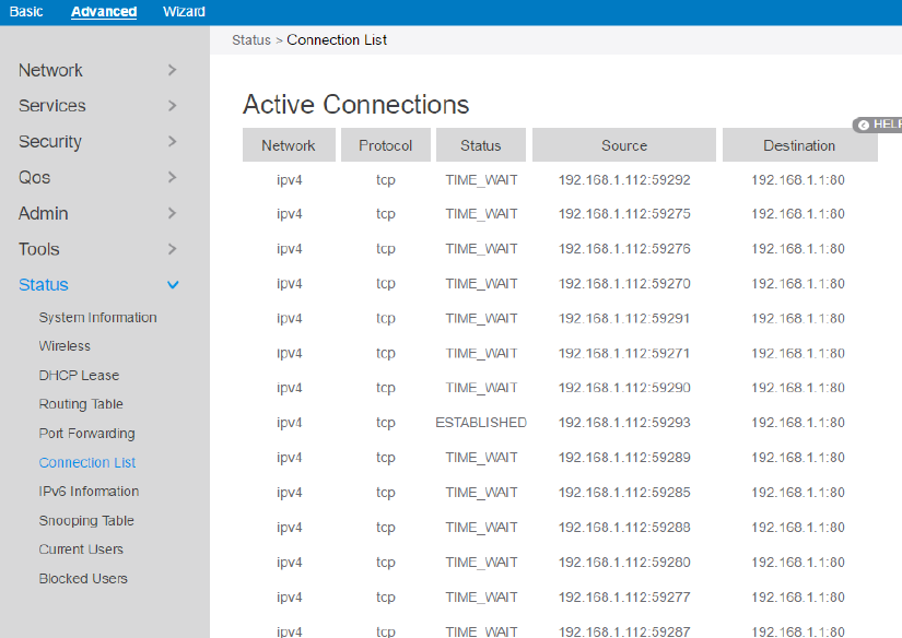
110
2.4.7.6 Connection List
Show active connections status information.
From the navigation panel, go to Advanced > Status > Connection List.
2.4.7.7 IPv6 Information
Shows details on WAN and LAN IPv6 information.
From the navigation panel, go to Advanced > Status > IPv6 Information.
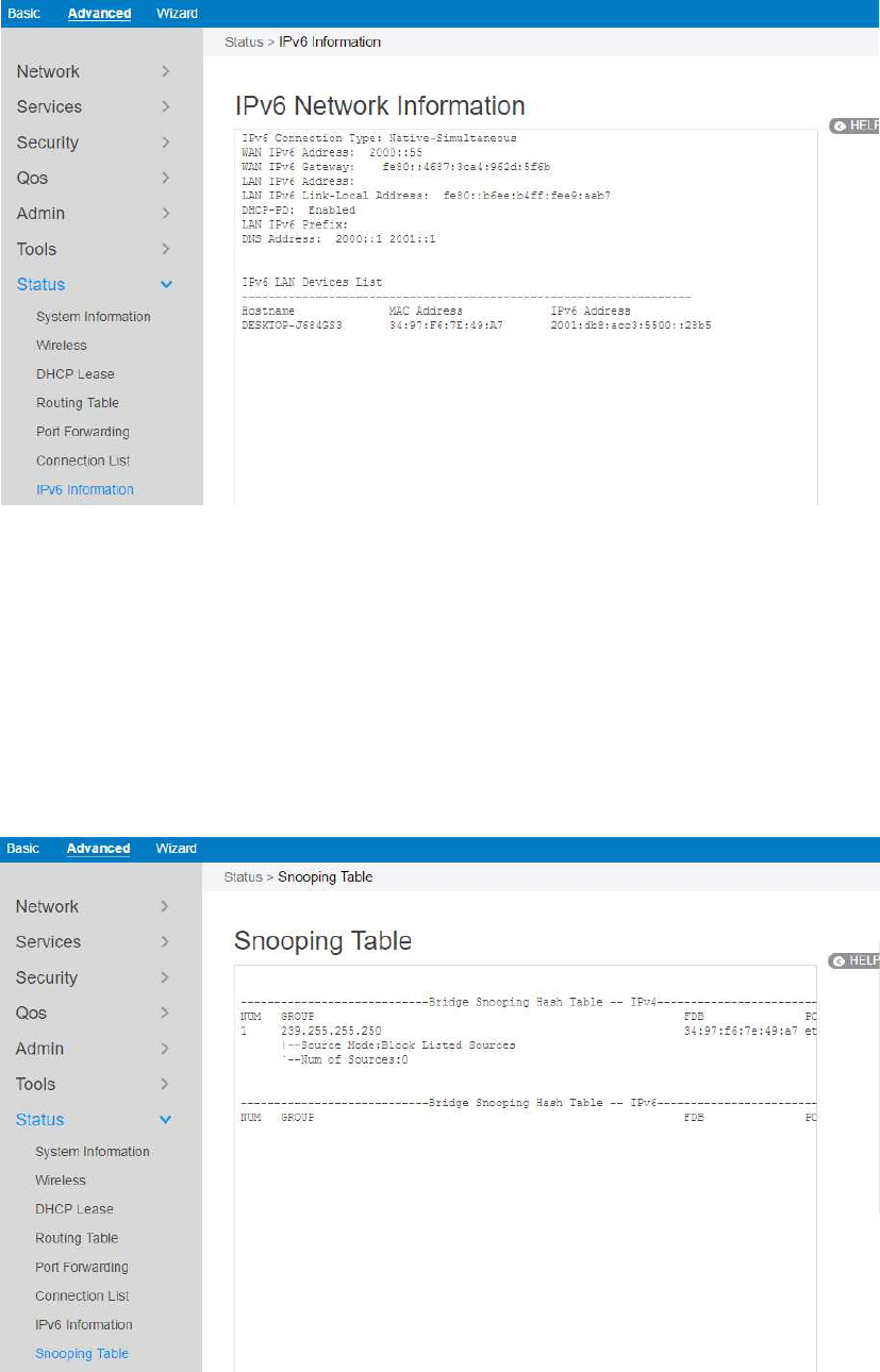
111
2.4.7.8 Snooping Table
Displays snooping table for client joins/leaves for both wired and wireless client
streams.
From the navigation panel, go to Advanced > Status > Snooping Table.
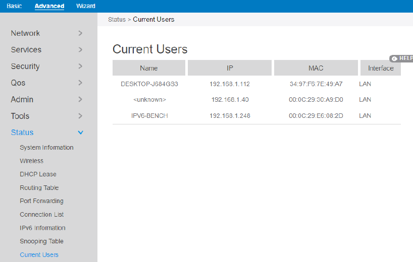
112
2.4.7.9 Current Users
Display current user who is permitted to get access to Internet through the router.
From the navigation panel, go to Advanced > Status > Current User Table.
2.4.7.10 Blocked Users
Display current users who are not permitted to get access to Internet through the
router.
From the navigation panel, go to Advanced > Status > Blocked User.
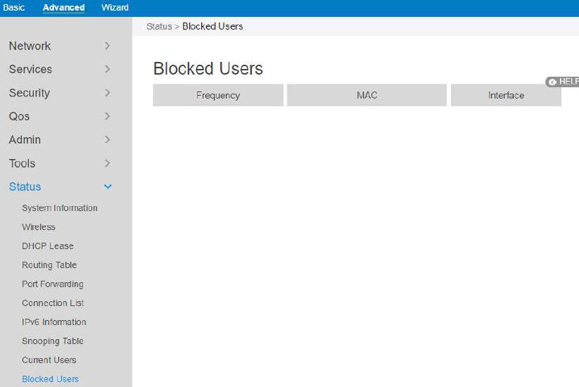
113
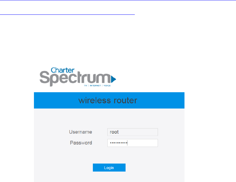
114
3 Root User Settings
You can login to the GUI as a root user for more configuration options. Root user
settings are hidden and cannot be configured by normal users.
3.1 Login
Root user of the router owns more privilege than Normal User. Following shows the
steps to log in Root User’s GUI:
1. Open a web browser and enter IP address:
http://192.168.1.1/a43edc96b945ff5d3c624838b54bf3f2/813dbdb6be123e5/ca6
c40542f5e7c4a59f66ca01028597a/login.html.
2. On the login page, enter the default root username: root, and password:
MmvGB^RY3#.
3. Use the Web GUI to configure various hidden settings of your wireless router.
3.2 Router
3.2.1 Static Routing
This module allows administrator to add routing rules for the router. This feature can
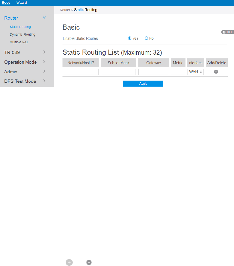
115
be useful when there are several devices who are connecting with router.
Steps to set Static Routing:
1. From the navigation panel, go to Root > Router > Static Routing.
2. Enable Static Routes: Select [Yes] to enable static routes.
3. Network/Host IP: The destination network or host of a route rule. It could be a
host address such as '192.168.123.11' or a network address such as '192.168.0.0'.
4. Subnet Mask: Indicates how many bits are for network ID and subnet ID. For
example: if the dotted-decimal Subnet Mask is 255.255.255.0, then its’ Subnet
Mask bits is 24. If the destination is a host, its Subnet Mask bits should be 32.
5. Gateway: This is the IP address of the gateway where packets are routed to. The
specified gateway must be setup and reachable first.
6. Metric: Metric is a value of distance for the network.
7. Interface: Network interface that the route rule will apply to.
8. Add/Delete: Click or to add/delete the profile.
9. When done, click Apply.
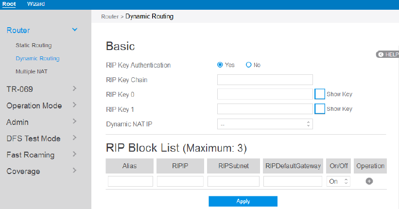
116
3.2.2 Dynamic Routing
Dynamic routing means router can automatically maintain its routing table. Dynamic
routing has two basic functions: maintain routing table, and exchange routing table
with other routers.
Steps to set up Dynamic Routing:
1. From the navigation panel, go to Root > Router > Dynamic Routing.
2. RIP Key Authentication: Enable or disable RIP key authentication mechanism
when switching route with other routers.
3. RIP Key Chain: RIP key name.
4. RIP Key 0: RIP key value of RIP Key 0.
5. RIP Key 1: RIP key value of RIP Key 0.
6. Dynamic NAT IP: Single IP address from Charter supplied public IP subnets
used for all internal hosts traffic flow.
7. Alias: Friendly identifier for managed element
8. RIPIP: IP address to be advertised.
9. RIPSubnet: Subnet mask for RIPIP.
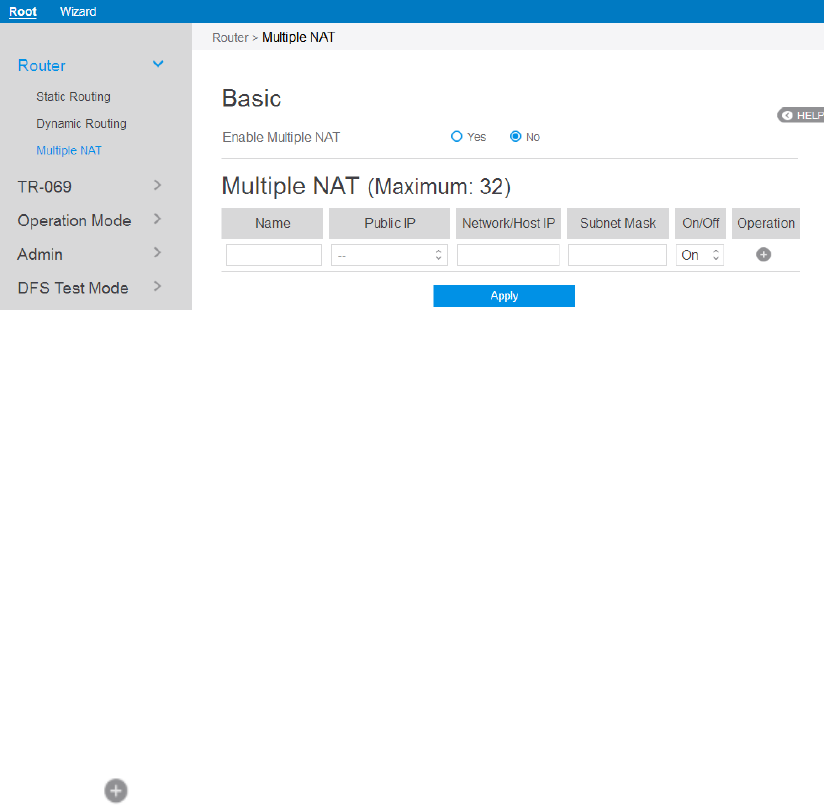
117
10. RIPDefaultGateway: Gateway IP for RIPIP
11. On/Off: Enable or disable this item rule.
12. When done, click Apply.
3.2.3 Multiple NAT
This can let you limit range of ipaddress that is going to use NAT function.
Steps to set Multiple NAT:
1. From the navigation panel, go to Root > Router > Multiple NAT.
2. Enable Multiple NAT: Check [Yes] to enable this function, Check [No] to
disable this function.
3. Name: The name for the item bar.
4. Public IP: IP address that Host IP will be mapped to.
5. Network/Host IP: IP address of the host reside on lan-side.
6. Subnet Mask: The subnet mask for lan-side IP address.
7. On/Off: Enable or disable the multiple NAT rule.
8. Click to add this item to the Multiple NAT List.
9. Click Apply.
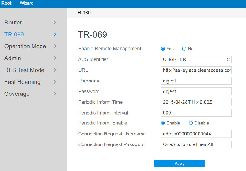
118
3.3 TR-069
TR-069 is a technical standard defined by DSL forum. Its full name is CPE WAN
management protocol. This module can provide a general framework and protocol to
a centralized router from remote Internet for next-generation network-management
family equipment configuration.
Steps to set TR-069:
1. From the navigation panel, go to Root > TR-069.
2. Enable Remote Management: Enable or disable TR-069 remote management.
3. ACS Identifier: Mark the current choice of connecting the ACS server is
CHARTER or TWC.
4. URL: ACS’s address is defined by an URL. Router(CPE) can communicate with
an ACS through an valid URL.
5. Username: Username used to authenticate the CPE when making a connection to
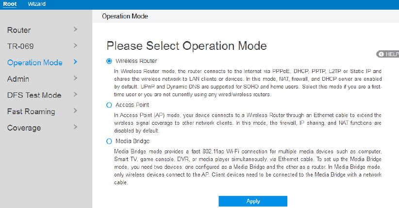
119
the ACS using the CPE WAN Management Protocol. This username is used only
for HTTP-based authentication of the CPE.
6. Password: Password used to authenticate the CPE when making a connection to
the ACS using the CPE WAN Management Protocol. This password is used only
for HTTP-based authentication of the CPE.
7. Periodic Inform Interval: An absolute time reference in UTC to determine when
the CPE will initiate the periodic Inform method calls. Each Inform call MUST
occur at this reference time plus or minus an integer multiple of the Periodic
Inform Interval.
8. Periodic Inform Enable: Whether or not the CPE MUST periodically send CPE
information to the ACS using the Inform method call.
9. Connection Request Username: Username used to authenticate an ACS making
a Connection Request to the CPE.
10. Connection Request Password: Password used to authenticate an ACS making a
Connection Request to the CPE.
11. Click Apply.
3.4 Operation Mode
The Operation Mode page allows you to select the appropriate mode for your network.
Select your mode: wireless router, access point or media bridge.
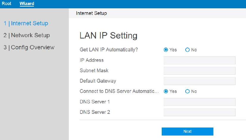
120
Steps to set operating mode:
1. From the navigation panel, go to Root > Operation Mode
2. Select the mode that you want the router to run.
3. Click Apply.
3.4.1 Wireless Router Mode
In wireless router mode, the router connects to the Internet via PPPoE, DHCP, PPTP,
L2TP or Static IP and shares the wireless network to LAN clients or devices. In this
mode, NAT, firewall, and DHCP server are enabled by default. UPnP and Dynamic
DNS are supported for SOHO and home users. Select this mode if you are a first-time
user or you are not currently using any wired/wireless routers. Select the wireless
router mode, and click Apply to jump to the wizard page, then refer to 1 wizard setup
for normal user setup.
3.4.2 Access Point Mode
In Access Point (AP) mode, your device connects to a wireless router through an
Ethernet cable to extend the wireless signal coverage to other network clients. In this
mode the firewall, IP sharing and NAT functions are disabled by default.
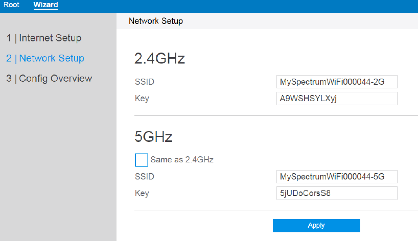
121
Steps to set up Access Point mode:
1. Click Apply, go to Wizard > Internet setup.
IP Address: The LAN IP address of wireless router. The default value is
192.168.1.1. In IP-based networks, data packets are sent to the network
devices' specific IP addresses.
Subnet Mask: The LAN subnet mask of wireless router. The default value is
255.255.255.0
DNS Server 1 & DNS Server 2: Either indicates the IP address of DNS
server that the wireless router will contact.
Click Next.
2. Assign the wireless network name (SSID) and security key for 2.4GHz and 5
GHz wireless connections.
SSID: The network name or SSID is a unique name that identifies the
wireless network. Wi-Fi devices automatically detect all networks within
range.
Key: A security key is the password that is assigned to secure a wireless
network from unauthorized access. To access a secured network, the user will
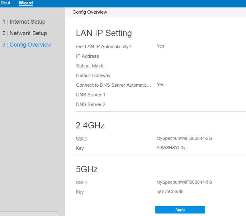
122
be asked to enter the security key.
When done, click Apply.
3. To display the new configuration information click Apply.
3.4.3 Media Bridge Mode
Media Bridge mode provides a fast 802.11ac Wi-Fi connection for multiple media
devices such as computer, Smart TV, game console, DVR, or media player
simultaneously, via Ethernet cable. To set up the Media Bridge mode, you need two
devices: one configured as a Media Bridge and the other as a router. In Media Bridge
mode, only wireless devices connect directly to the router/AP. Client devices need to
be connected to the Media Bridge with a network cable. Select Media Bridge mode.
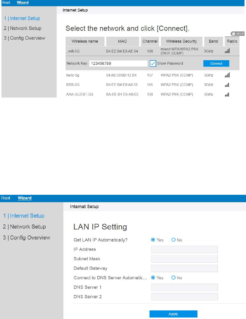
123
To set up Media Bridge mode:
1. Click Apply, go to Wizard > Internet setup.
Select the wireless network to connect your media bridge to and enter the
password.
When done, click Connect.
2. Input LAN IP information and click Apply.
IP Address: The LAN IP address of wireless router. The default value is
192.168.1.1. In IP-based networks, data packets are sent to the network
devices' specific IP addresses.
Subnet Mask: The LAN subnet mask of wireless router. The default value is
255.255.255.0
DNS Server 1 & DNS Server 2: Either indicates the IP address of DNS
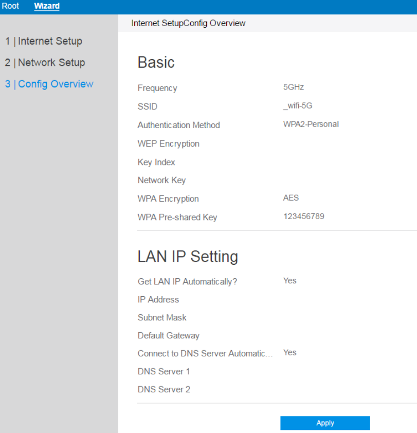
124
server that the router will contact.
3. To display the new configuration information click Apply.
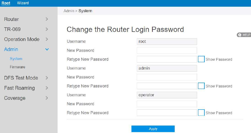
125
3.5 Admin
3.5.1 System
Through this module, administrator can change admin’s password, root’s login
password and operator’s password .
Steps to change the router login password:
1. From the navigation panel, go to Root > Admin.
2. New Password: Enter the new password you wish to use.
3. Retype New password: Retype your new password for confirmation.
4. When done, click Apply.
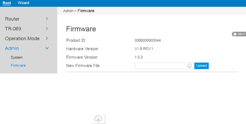
126
3.5.2 Firmware
This module enable administrator to upgrade firmware through web.
Steps to upgrade firmware:
1. From the navigation panel, go to Root > Admin > Firmware.
2. New Firmware File: Click to locate the firmware file.
3. Click Upload.
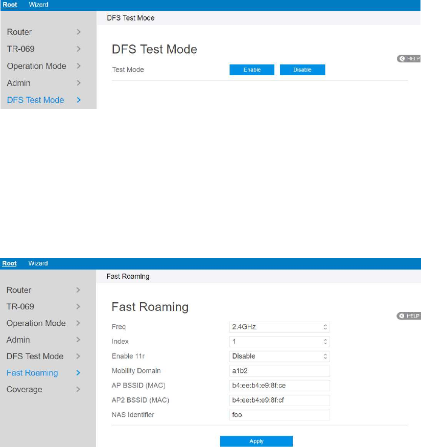
127
3.6 DFS Test Mode
This module is used to test wireless switch.
1. From the navigation panel, go to Root > DFS Test Mode.
2. Test Mode: Enable or disable DFS test mode.
3.9 Fast Roaming
Set up fast roaming for smooth client roaming between SSIDs.
Steps to set up Fast Roaming:
1. From the navigation panel, go to Root > Fast Roaming.
2. Freq: Select 2.4GHz or 5GHz WiFi frequency to configure.
3. Index: Select which index to configure.
4. Enable 11r: Enable or disable 11r (Fast Roaming).
5. Mobility Domain: Set 11r mobility domain.
128
6. AP BSSID (MAC): Your/our AP’s MAC Address.
7. AP2 BSSID (MAC): Other AP’s MAC Address.
8. NAS Identifier: NAS ID of AP.
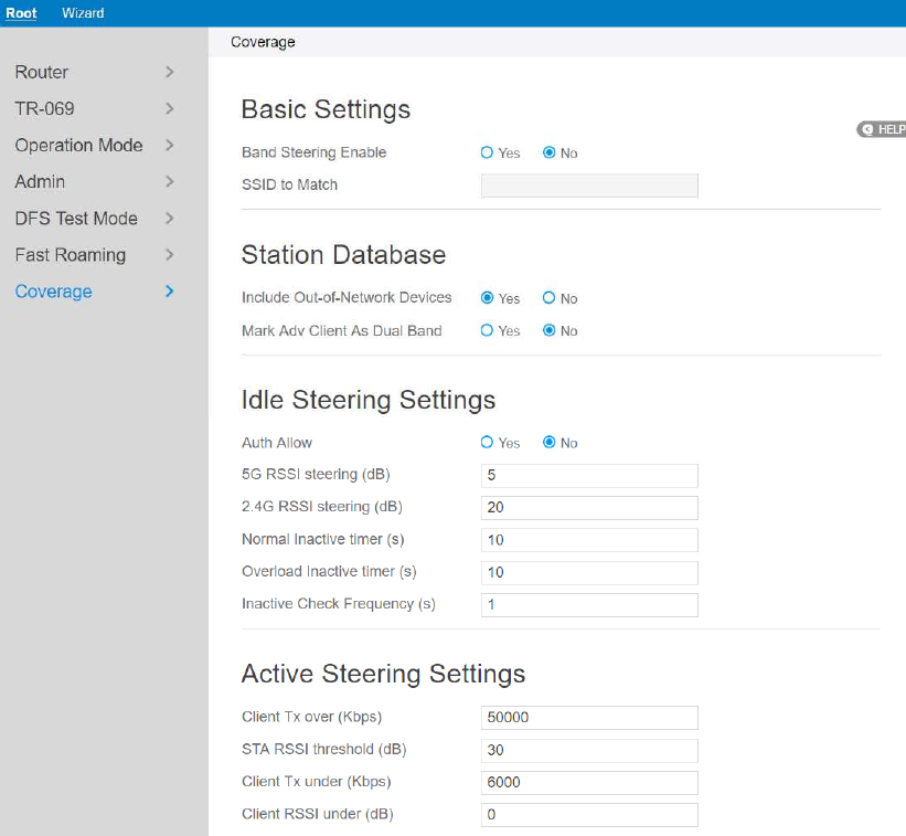
129
3.10 Coverage
Coverage allows automatic network switching according to the strength of the signal
(2.4GHz or 5GHz) to maintain optimum signal condition.
Steps to set up Coverage:
1. From the navigation panel, go to Root> Coverage.
2. Basic Settings:
Band Steering Enable: Enable or disable load balancing logic. Whole Home
Coverage brings some new steering mechanisms and algorithms in the Load
Balancing Daemon (lbd) to handle more scenarios and make use of features
supported on newer Wi-Fi devices.
SSID to match: The SSID to match when limiting band steering to only a
130
single SSID.
3. Station Database:
Include Out-of-Network Devices: Whether out of network devices should
be included in the database or not.
Mark Adv Client As Dual Band: Whether mark advertisement client as daul
band should be included in the database or not.
4. Idle Steering Settings:
5G RSSI steering (dB): RSSI value indicating a node associated on 5GHz
should be steered to 2.4GHz (dB).
2.4G RSSI steering (dB): RSSI value indicating a node associated on
2.4GHz should be steered to 5GHz (dB).
5. Active Steering Settings:
Client Tx over(Kbps): When the client Tx rate increases beyond this
threshold, generate an indication (Kbps).
STA RSSI threshold(dB): When evaluating a STA for rate-based upgrade
steering, the RSSI must also be above this threshold (dB).
Client Tx under(Kbps): When the client Tx rate decreases beyond this
threshold, generate an indication (Kbps).
Client RSSI under(dB): When the client RSSI decreases beyond this
threshold, generate an indication (dB).
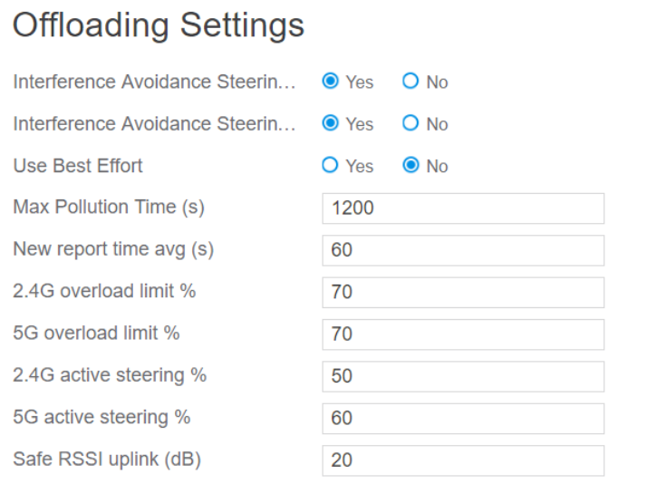
131
6. Offloading Settings:
New report time avg (s): Time to average before generating a new
utilization report (s).
2.4G overload limit %: Medium utilization threshold for an overload
condition on 2.4GHz (%).
5G overload limit %: Medium utilization threshold for an overload
condition on 5GHz (%)
2.4G active steering %: Medium utilization safety threshold for active
steering to 2.4GHz (%).
5G active steering %: Medium utilization safety threshold for active
steering to 5GHz (%)
Safe RSSI uplink (dB): Uplink RSSI (in dB) above which association will
be considered safe.
7. Steering Executor Settings:
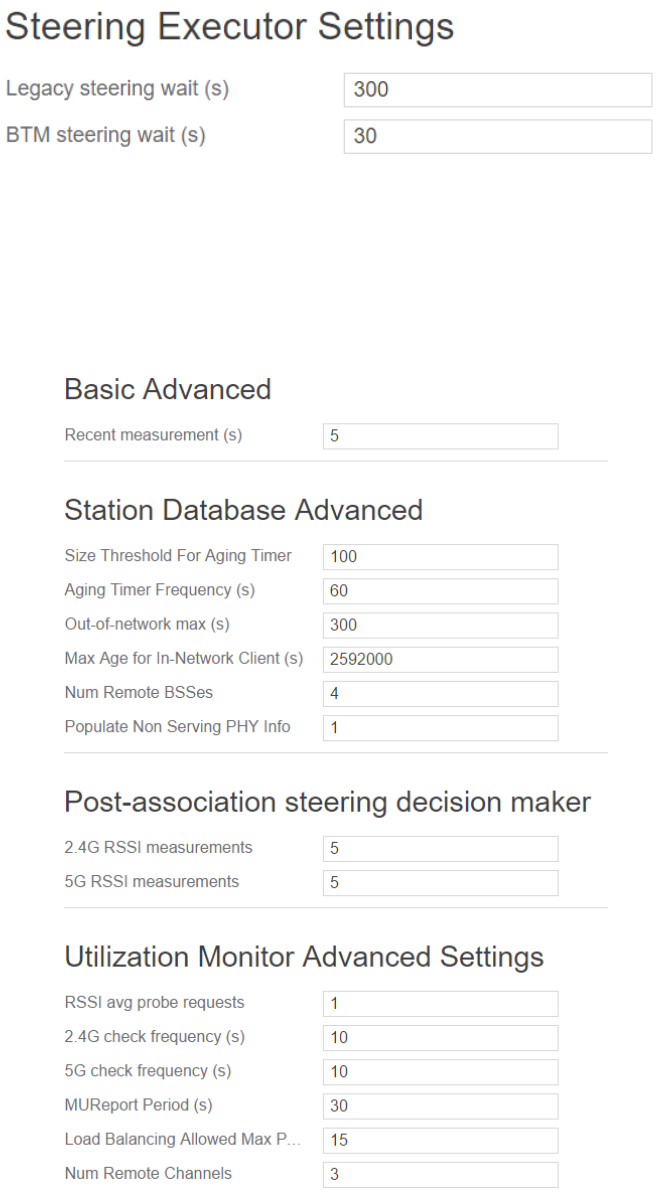
132
Legacy steering wait (s): Time to wait before steering a legacy client again
after completing steering (s).
BTM steering wait (s): Time to wait before steering a client via BTM again
after completing steering without sending an auth reject (s).
8. Basic Advanced:
Recent measurement (s): Maximum number of seconds elapsed allowed for
a 'recent' measurement.
9. Station Database Advanced:
133
Out-of-network max (s): Max Age for Out-of-Network Client (s).
10. Post-association steering decision maker:
2.4G RSSI measurements: Number of RSSI measurements on 2.4GHz
band.
5G RSSI measurements: Number of RSSI measurements on 5GHz band.
11. Utilization Monitor Advanced Settings:
RSSI avg probe requests: Number of probe requests required for the RSSI
averaging.
2.4G check frequency(s): The frequency to check medium utilization on
2.4GHz .
5G check frequency(s): The frequency to check medium utilization on
5GHz.
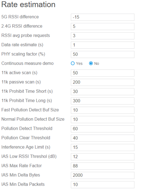
134
12. Rate estimation:
5G RSSI difference: Difference when estimating 5GHz RSSI value from the
one measured on 2.4GHz.
2.4G RSSI difference: Difference when estimating 2.4GHz RSSI value from
the one measured on 5GHz.
RSSI avg probe requests: Number of probe requests required for the RSSI
averaging.
Data rate estimate (s): Seconds between successive stats samples for
estimating data rate.
PHY scaling factor (%): Scaling factor (as percentage) for converting PHY
rate to upper layer rate for airtime computations.
Continuous measure demo: Continuously measure throughput (for demo
135
purposes only).
11k active scan (s): Active scan duration used in 802.11k Beacon Report (s).
11k passive scan (s): Passive scan duration used in 802.11k Beacon Report
request (s).
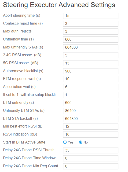
136
13. Steering Executor Advanced Settings:
Abort steering time (s): Maximum time for client to associate on target band
before AP aborts steering (s).
Coalesce reject time (s): Time to coalesce multiple authentication rejects
down to a single one (s).
Max auth. Rejects: Max consecutive authentication rejects after which the
device is marked as steering unfriendly.
Unfriendly time (s): The base amount of time a device is considered steering
unfriendly before another attempt (s).
Max unfriendly STAs (s): The maximum time used for backoff for steering
unfriendly STAs. Total amount of backoff is calculated as min
(MaxSteeringUnfriendly, SteeringUnfriendlyTime * 2 ^
CountConsecutiveFailures) (s).
137
2.4G RSSI assoc. (dB): RSSI threshold indicating 2.4GHz band is not strong
enough for association (dB).
5G RSSI assoc. (dB): RSSI threshold indicating 5GHz band is not strong
enough for association (dB).
Autoremove blacklist (s): The amount of time (in seconds) before
automatically removing the blacklist (s).
BTM response wait (s): The amount of time to wait for a BTM response (s).
Association wait (s): The amount of time to wait for an association on the
correct band after receiving a BTM response (s).
BTM unfriendly (s): The base amount of time a device is considered
BTM-steering unfriendly before another attempt to steer via BTM (s).
Unfriendly BTM STAs (s): The maximum time used for backoff for BTM
unfriendly STAs. Total amount of backoff is calculated as min
(MaxBTMUnfriendly, BTMUnfriendlyTime * 2 ^ CountConsecutiveFailures)
(s).
BTM STA backoff (s): The maximum time used for backoff for BTM STAs
that fail active steering. Total amount of backoff is calculated as min
(MaxBTMActiveUnfriendly, BTMUnfriendlyTime * 2 ^
CountConsecutiveFailures) (s).
Min best effort RSSI dB: The minimum RSSI, below which lbd will only
steer clients via best effort (no blacklists, failures do not mark as unfriendly)
(dB).
RSSI indication (dB): RSSI threshold to generate an indication when a
client crosses it (dB).
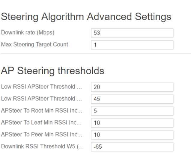
138
14. Steering Algorithm Advanced Settings
Downlink rate (Mbps): Downlink rate (in Mbps) should exceed at least Low
TxRateXingThreshold + this value, when steering from 2.4GHz to 5GHz due
to overload.
139
4.0 FCC Statement:
Federal Communication Commission Interference Statement
This equipment has been tested and found to comply with the limits for a Class B
digital device, pursuant to Part 15 of the FCC Rules. These limits are designed to
provide reasonable protection against harmful interference in a residential installation.
This equipment generates, uses and can radiate radio frequency energy and, if not
installed and used in accordance with the instructions, may cause harmful interference
to radio communications. However, there is no guarantee that interference will not
occur in a particular installation. If this equipment does cause harmful interference to
radio or television reception, which can be determined by turning the equipment off
and on, the user is encouraged to try to correct the interference by one of the
following measures:
● Reorient or relocate the receiving antenna.
● Increase the separation between the equipment and receiver.
● Connect the equipment into an outlet on a circuit different from that to which the
receiver is connected.
● Consult the dealer or an experienced radio/TV technician for help.
FCC Caution: Any changes or modifications not expressly approved by the party
responsible for compliance could void the user’s authority to operate this equipment.
This device complies with Part 15 of the FCC Rules. Operation is subject to the
following two conditions: (1) This device may not cause harmful interference, and (2)
this device must accept any interference received, including interference that
may cause undesired operation.
For product available in the USA/Canada market, only channel 1~11 can be operated.
Selection of other channels is not possible.
140
This device is restricted for indoor use.
IMPORTANT NOTE:
FCC Radiation Exposure Statement:
This equipment complies with FCC radiation exposure limits set forth for an
uncontrolled environment. This equipment should be installed and operated with
minimum distance 25 cm between the radiator & your body.