Askey Computer TCG310 Access Point User Manual UM PKE2048JM U84 RoHS TCG310 V1 0 20170502 1
Askey Computer Corp Access Point UM PKE2048JM U84 RoHS TCG310 V1 0 20170502 1
UserManual.wiki
>
Askey Computer
>
TCG310 User Manual
>
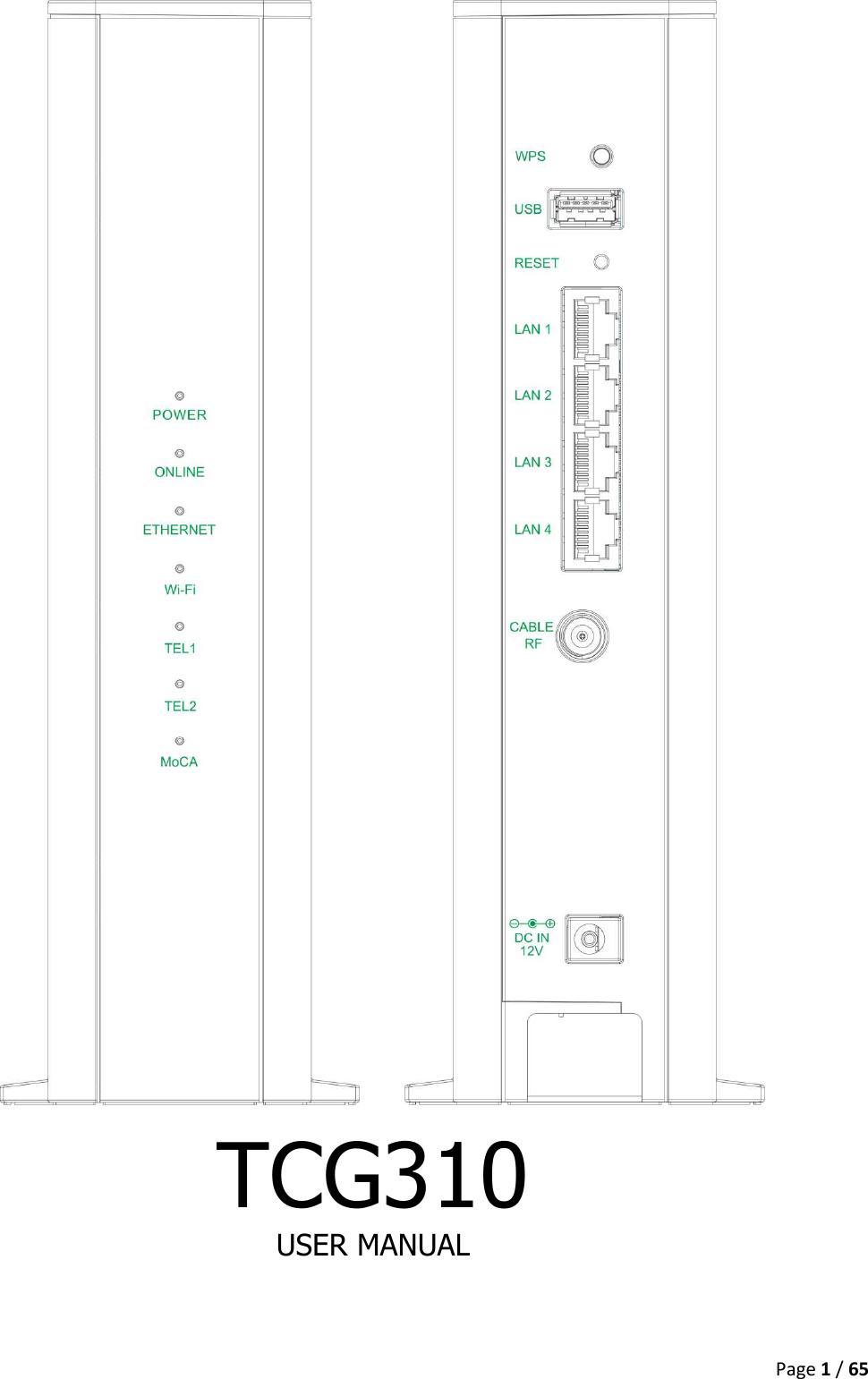
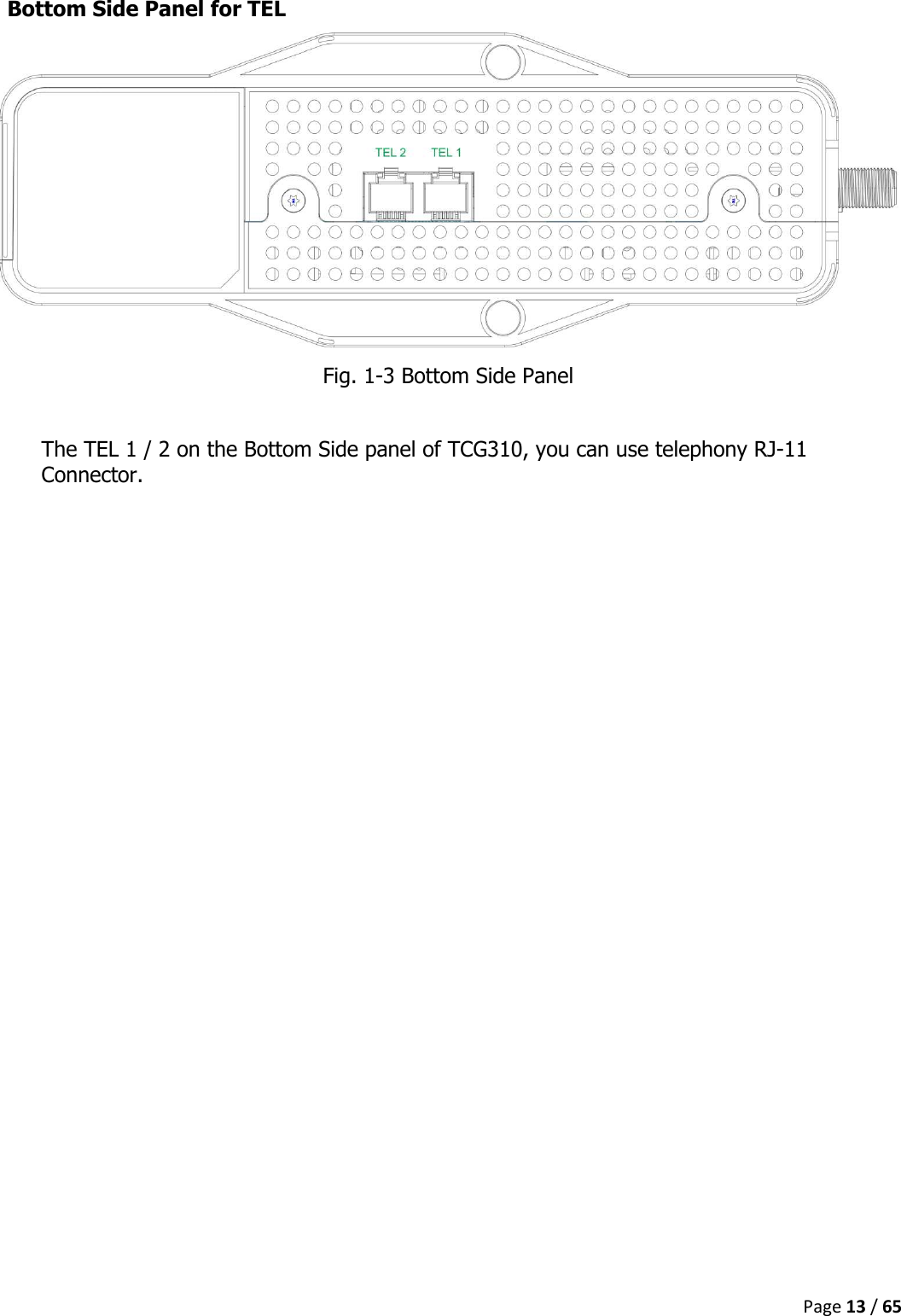
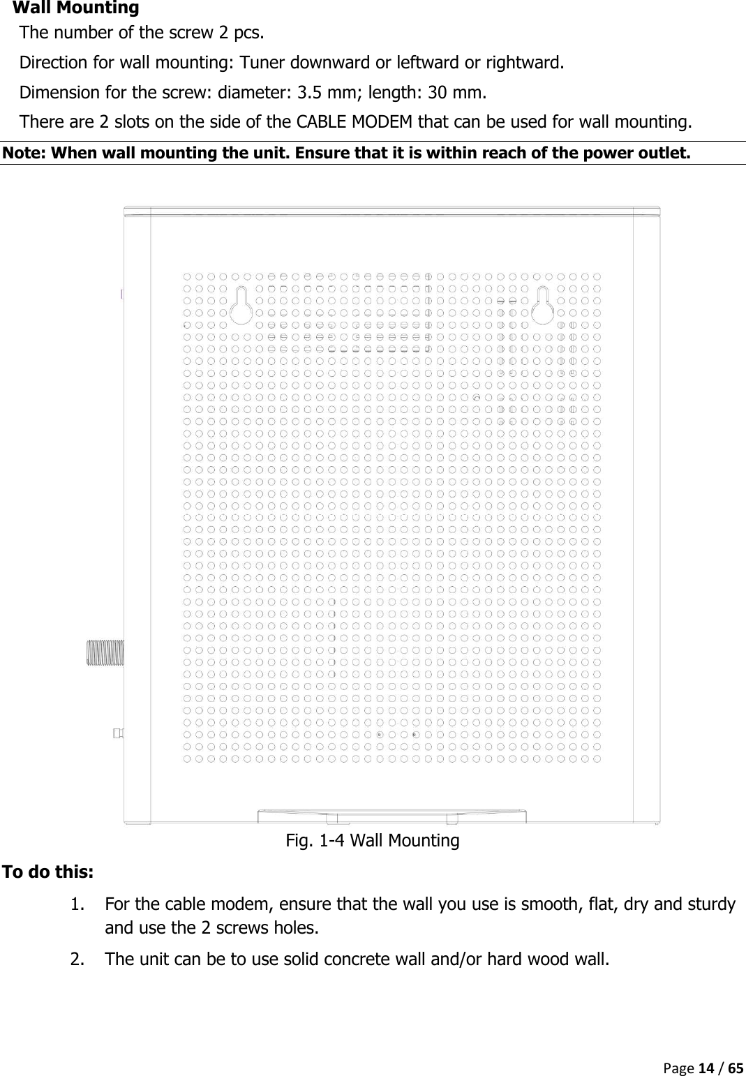
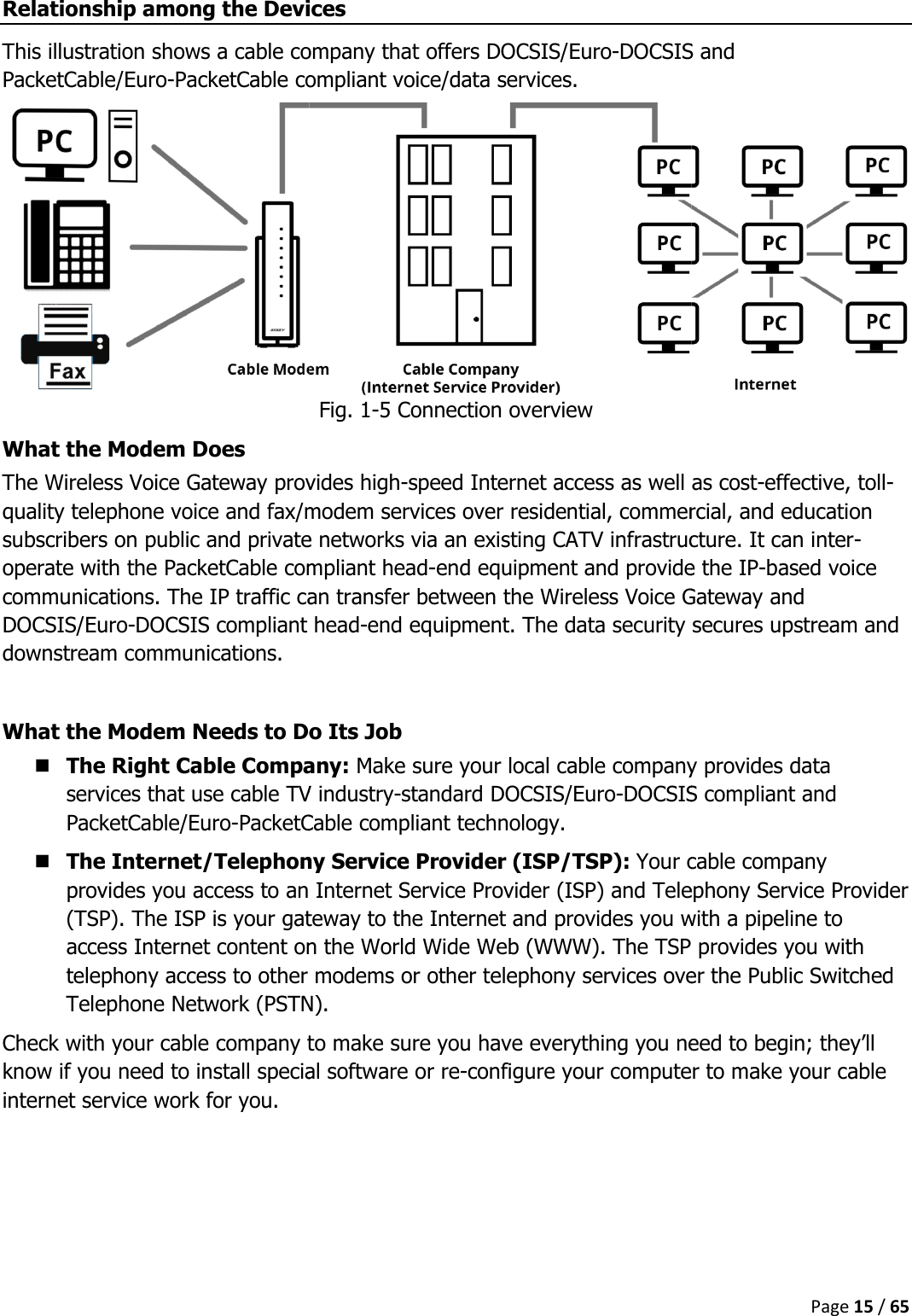
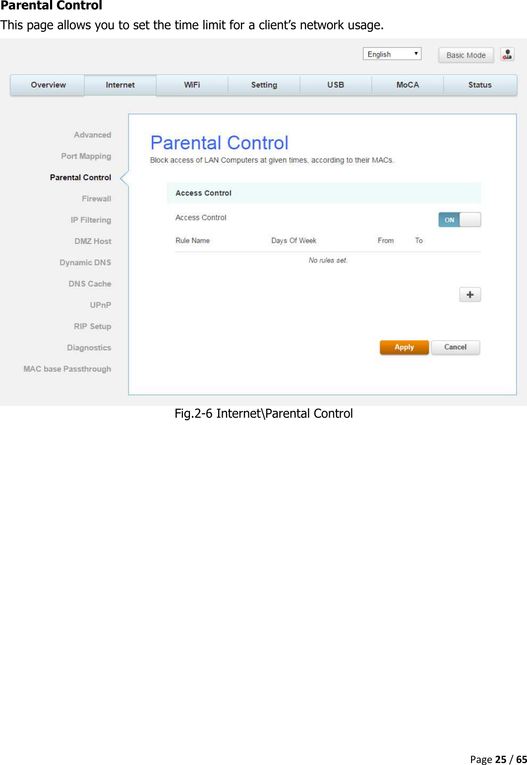
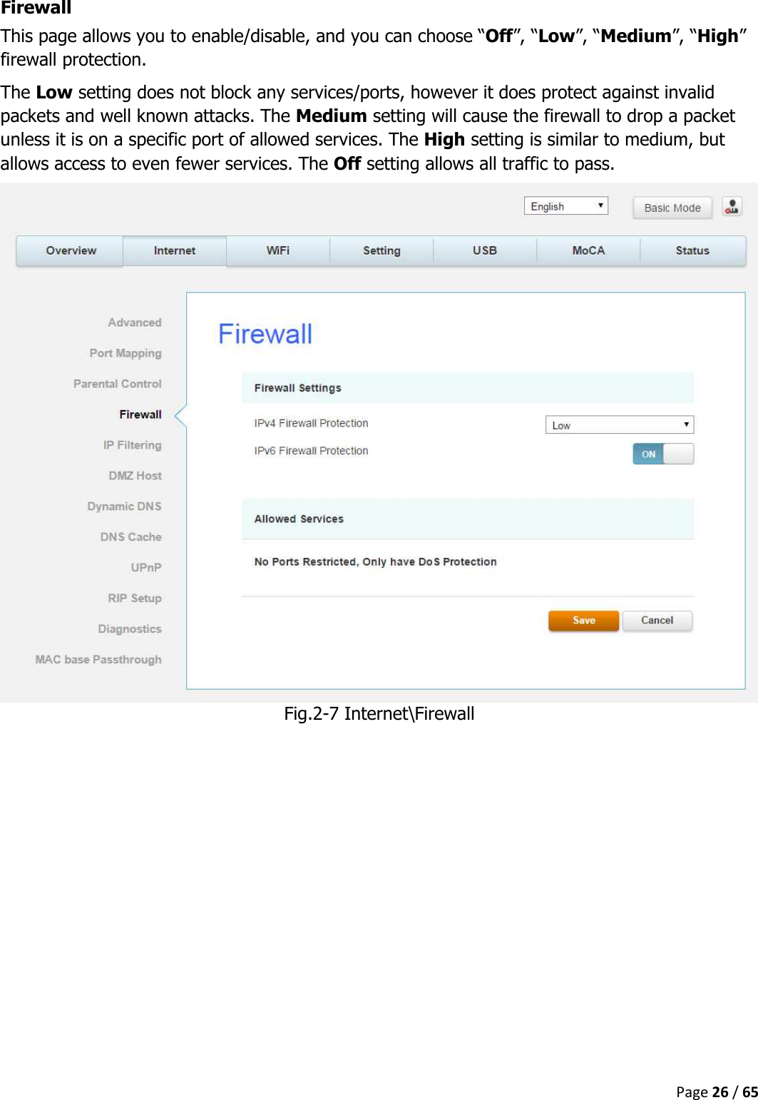
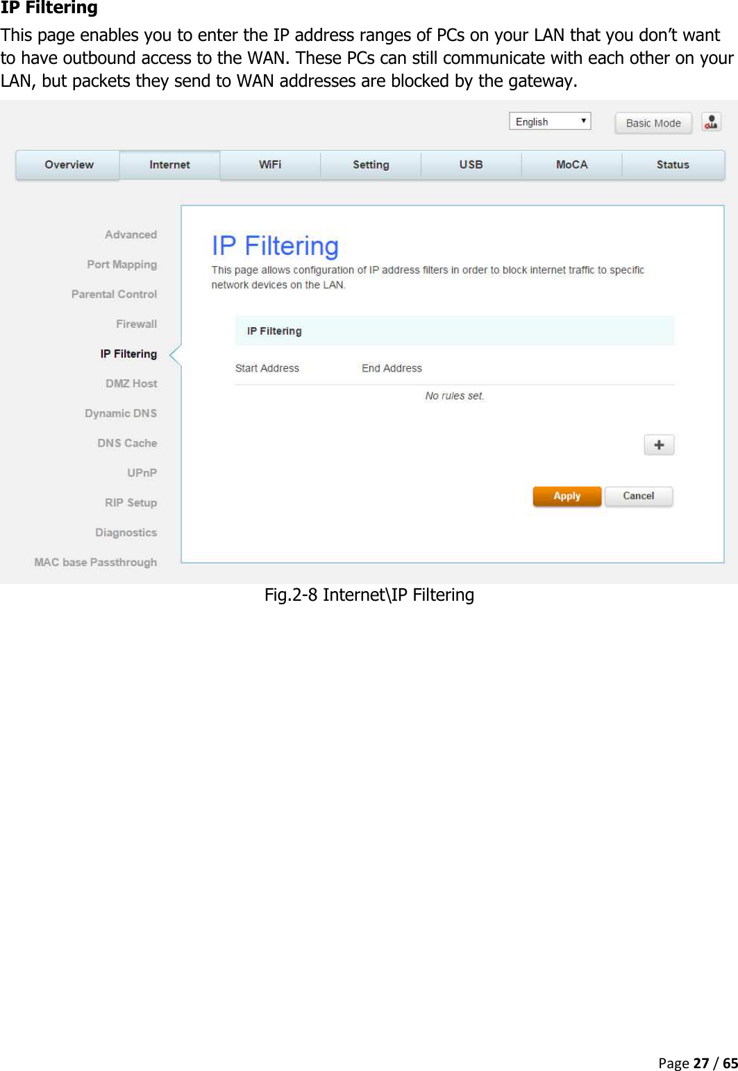
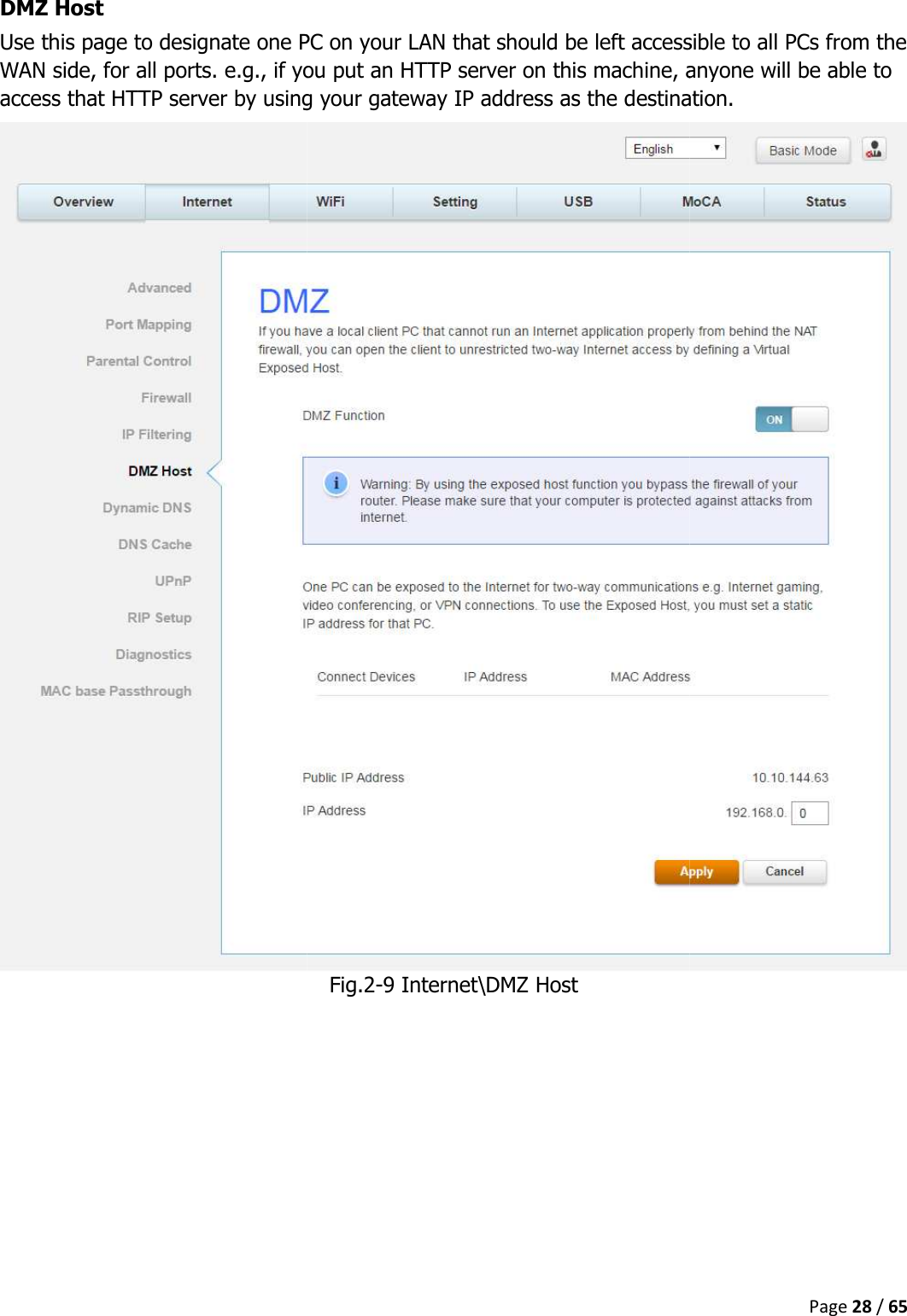
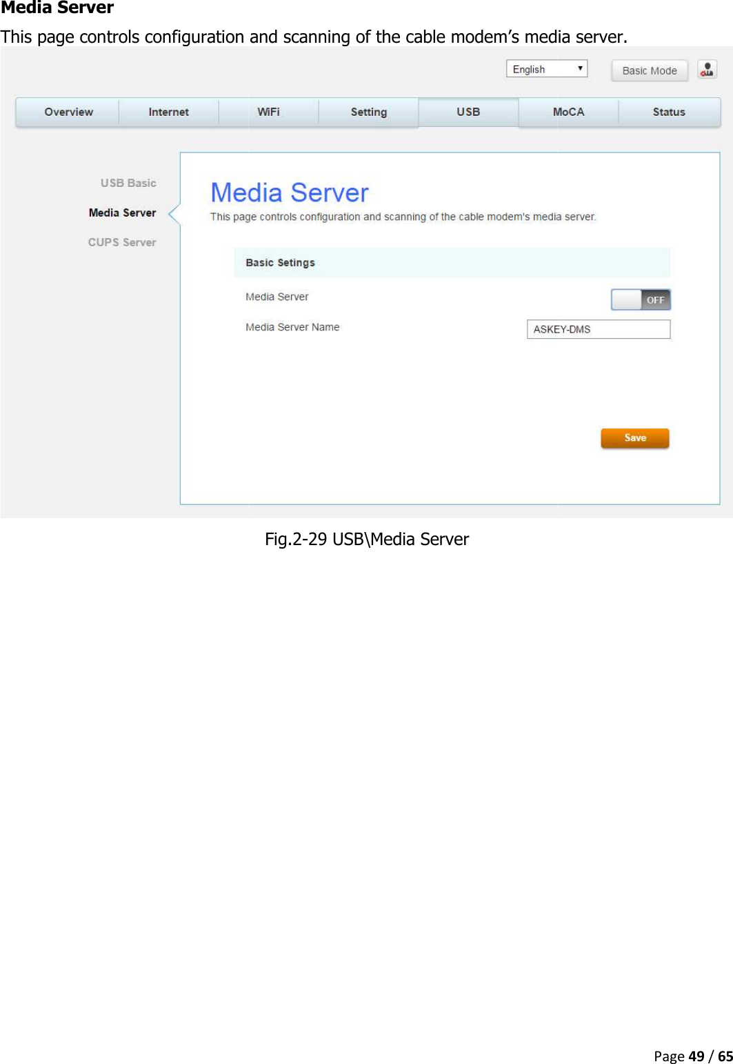
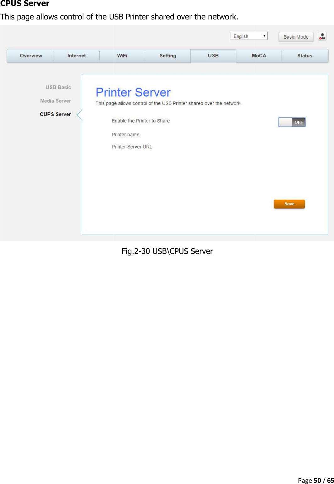
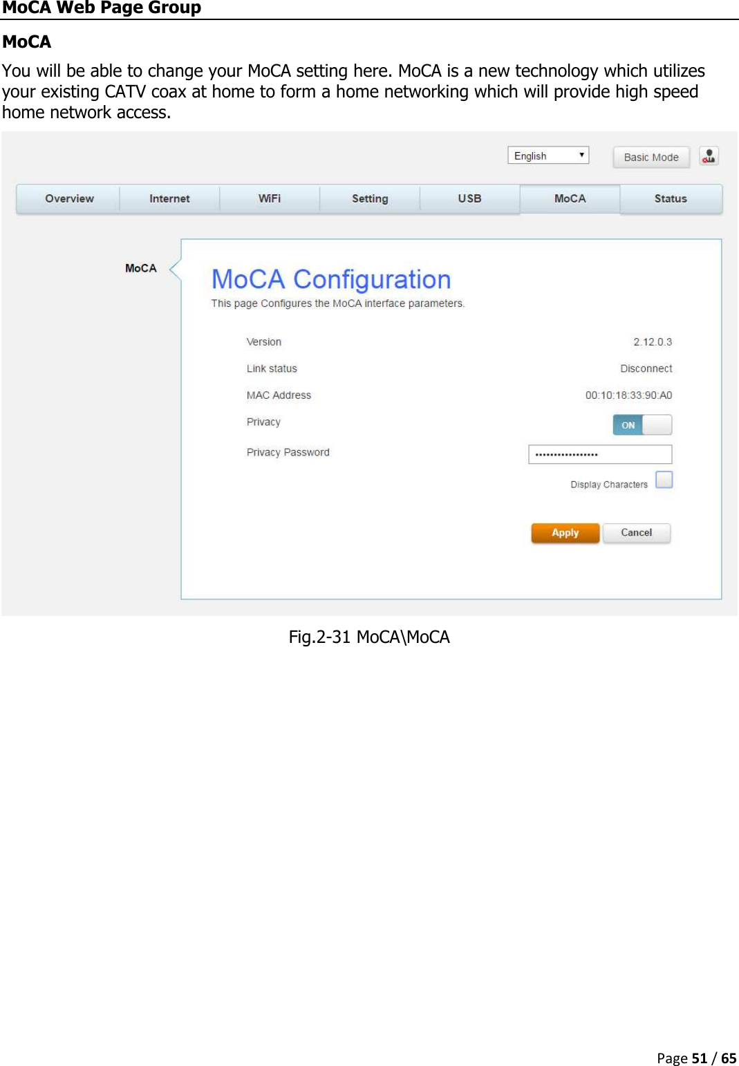
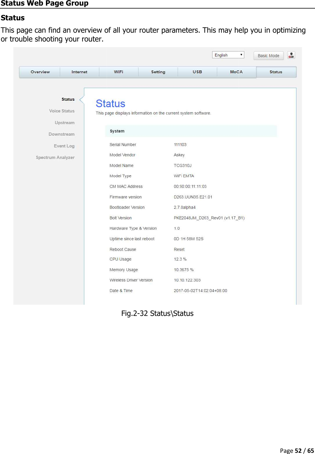
User Manual
Contents
1.
User Manual
2.
Users Manual_rev2.pdf
3.
Technical-User Manual_rev.1.pdf
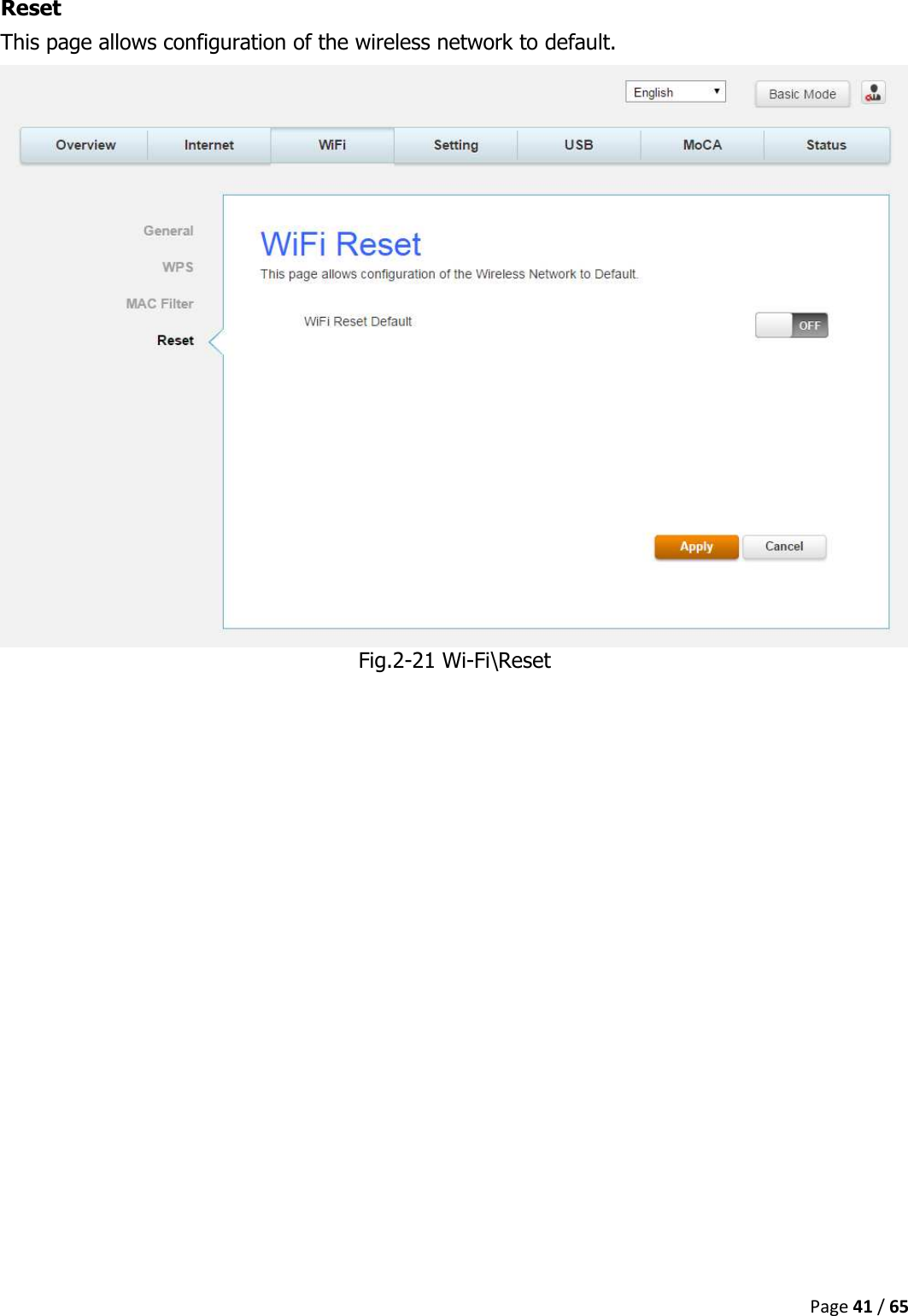
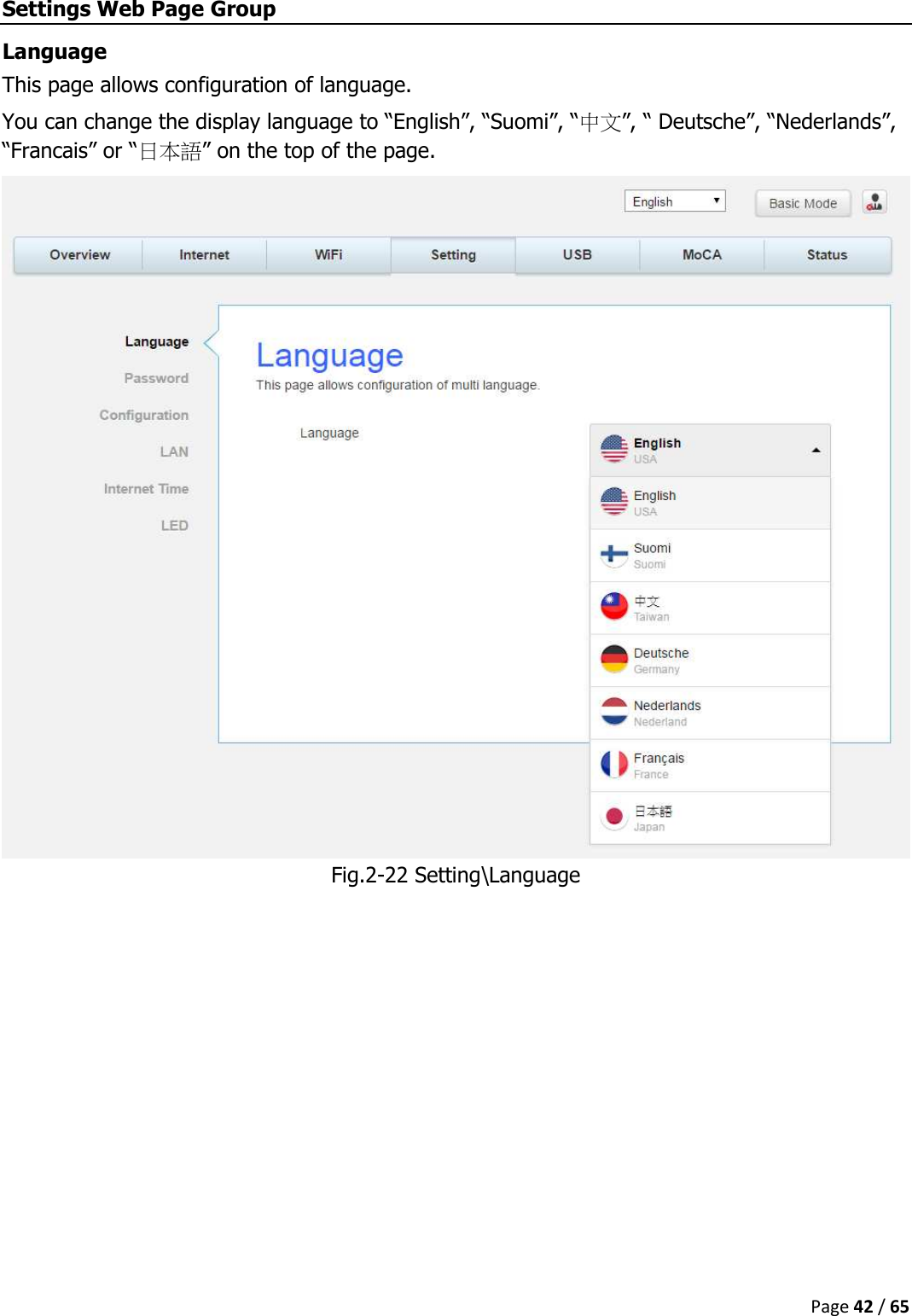
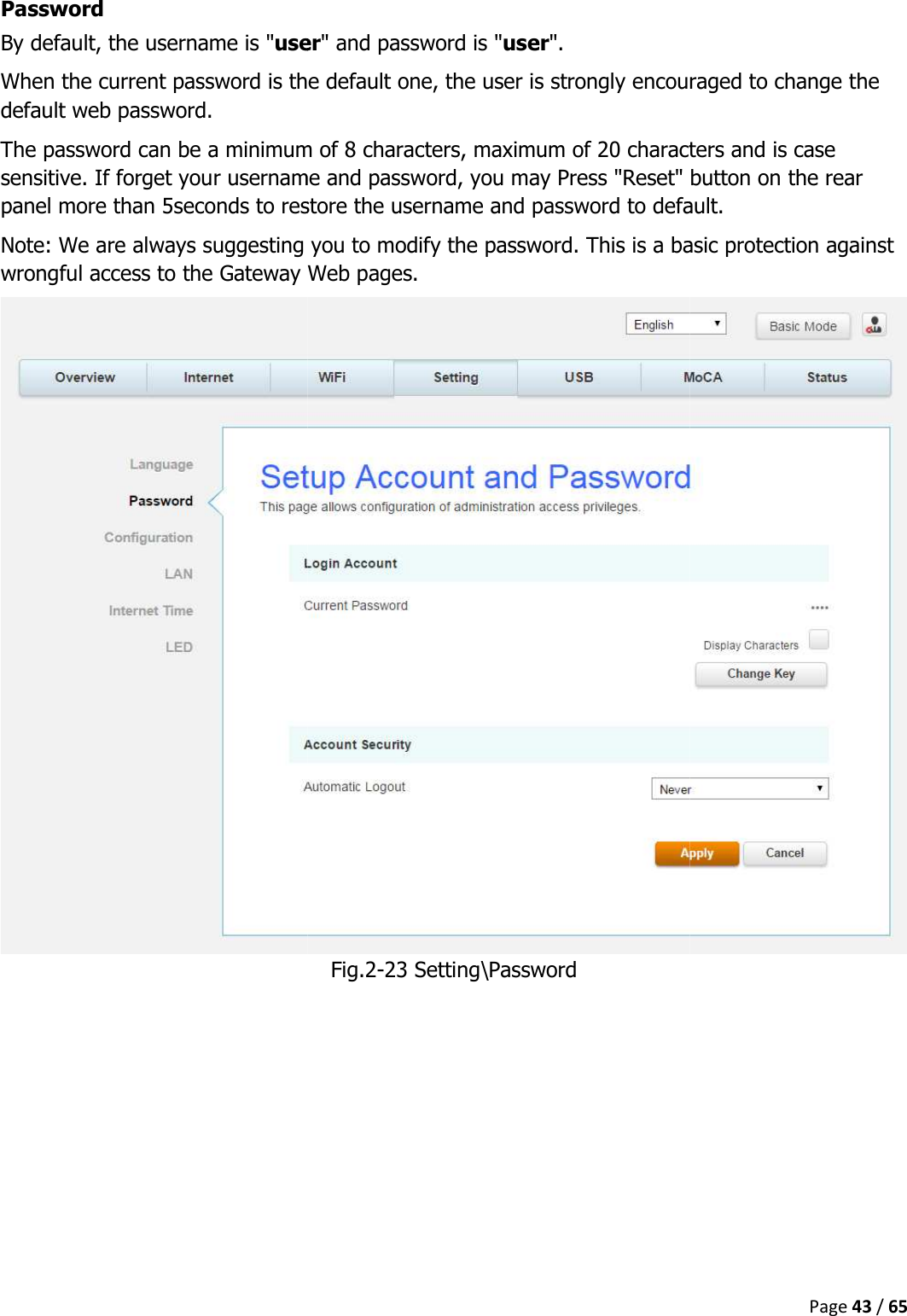
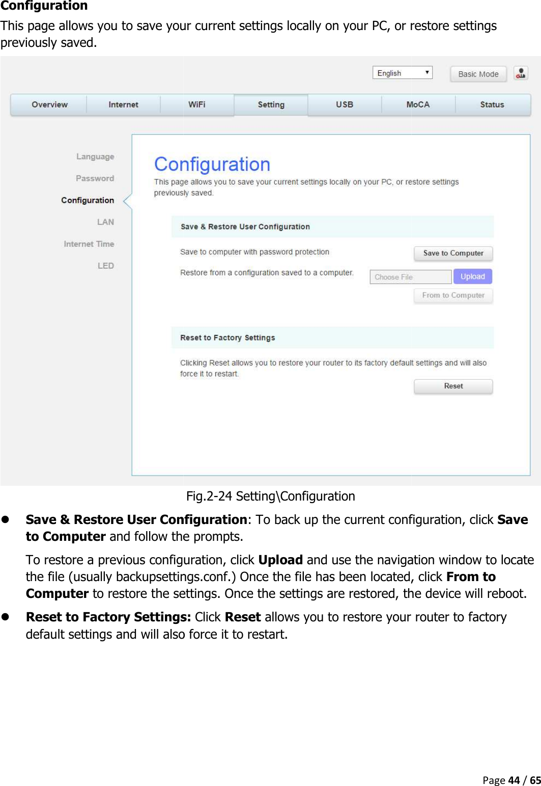
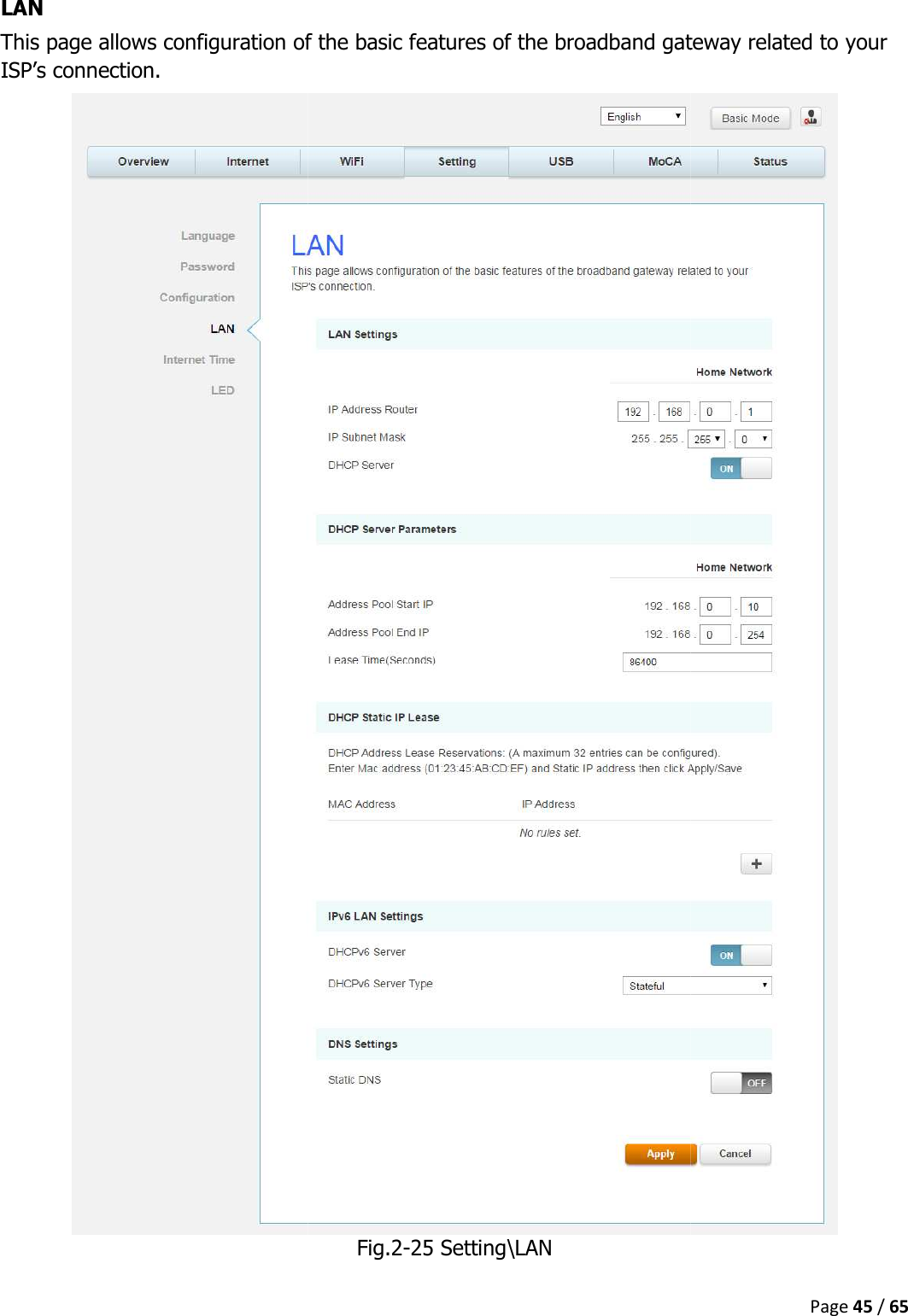
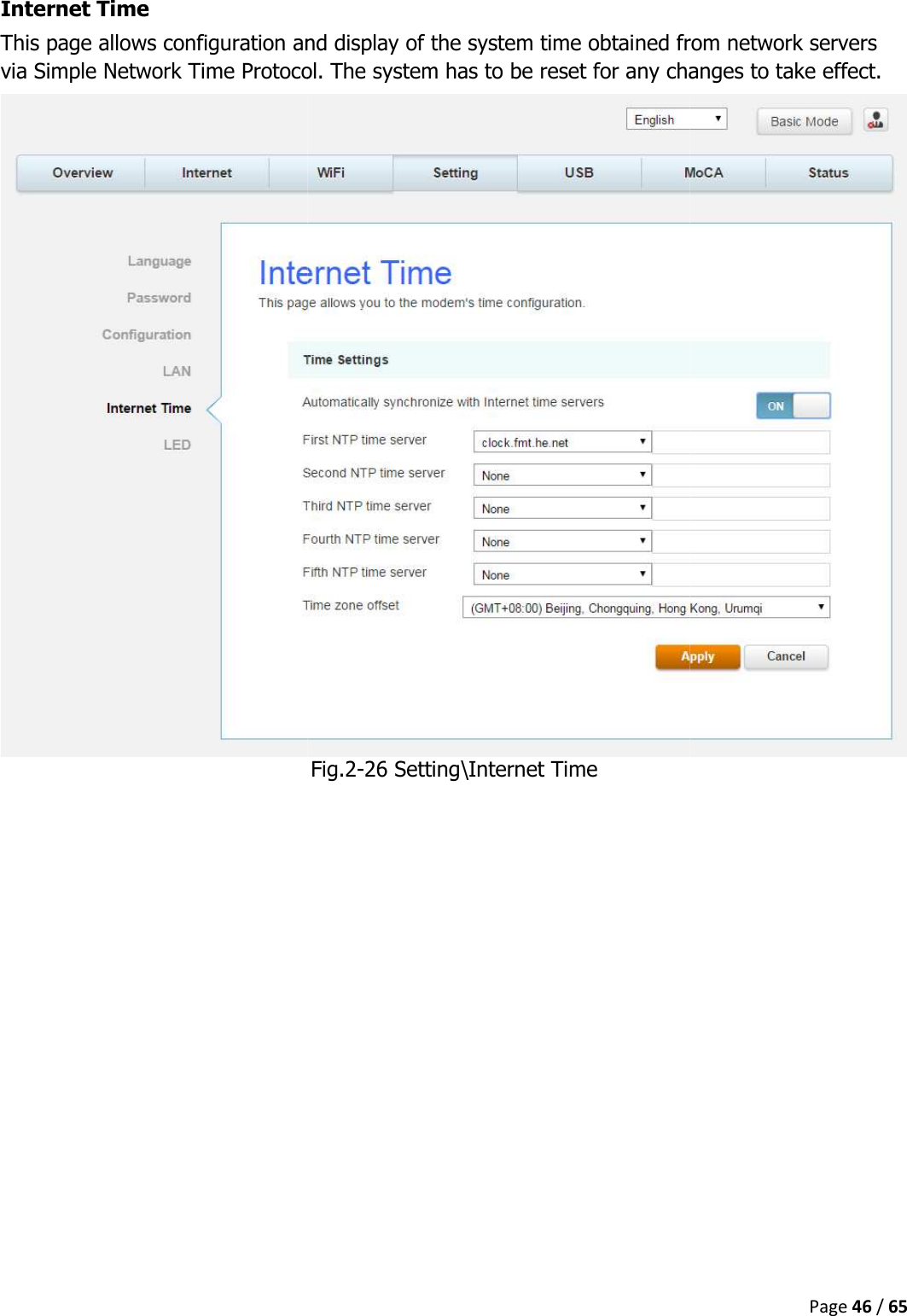
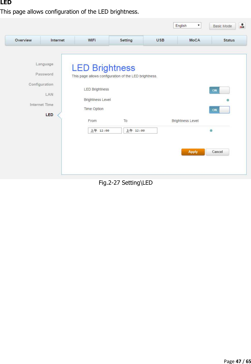
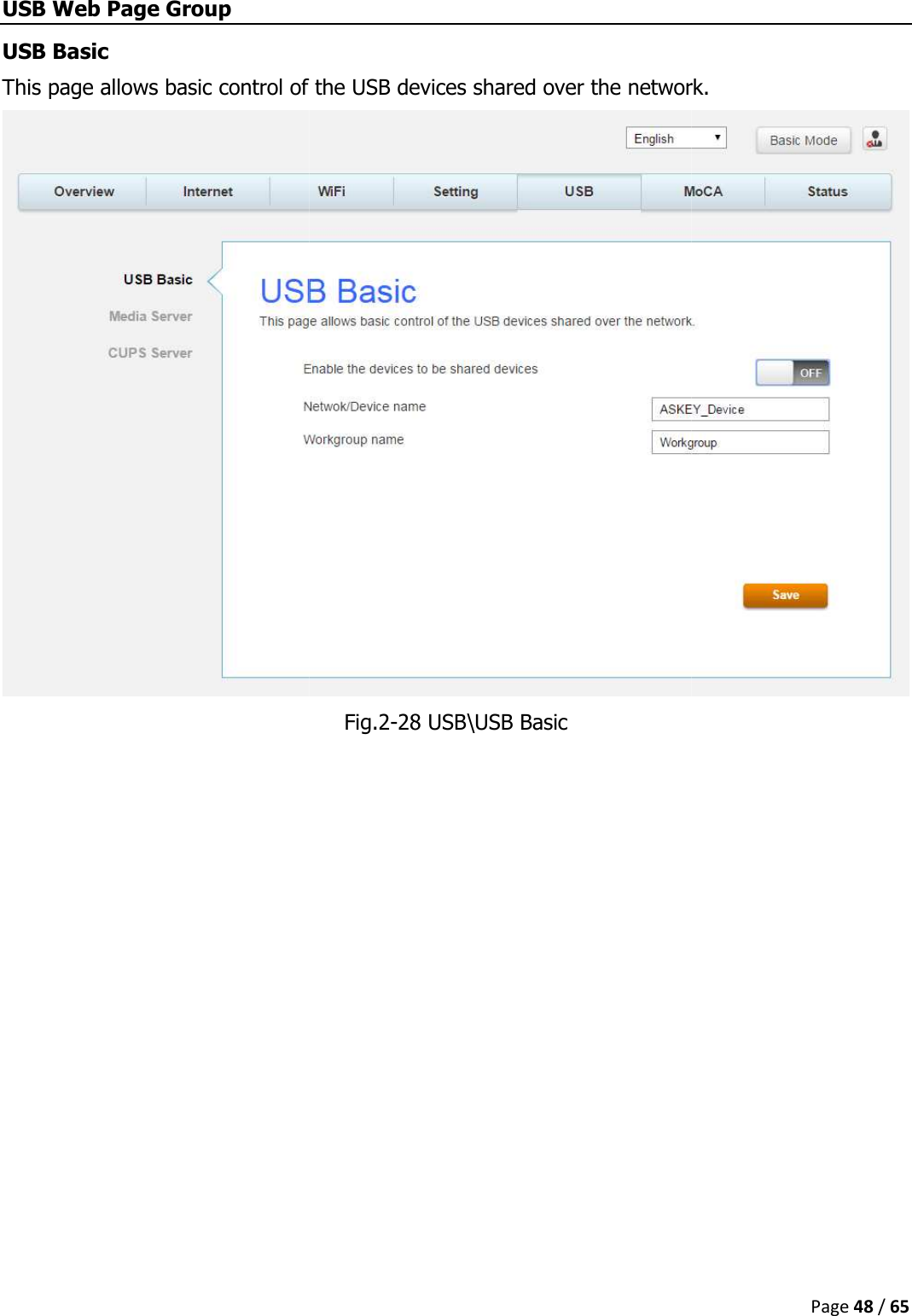
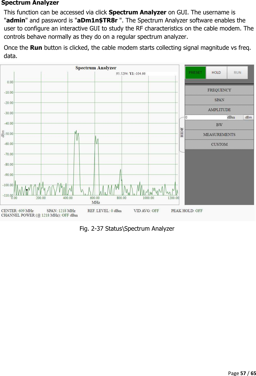
User Manual
Navigation menu
Upload a User Manual
Namespaces
Wiki Guide
HTML
PDF
Info
Views
User Manual
Discussion / Help
Navigation