Askey Computer TCG310 Cable Modem User Manual rev2
Askey Computer Corp Cable Modem Users Manual rev2
UserManual.wiki
>
Askey Computer
>
TCG310 User Manual
>
Users Manual_rev2.pdf
Contents
1.
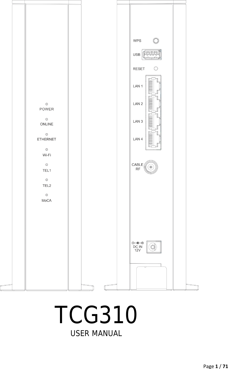
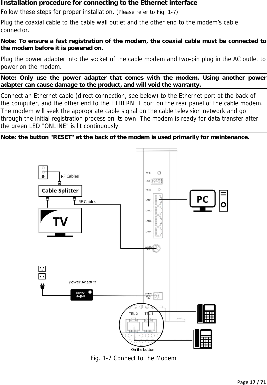
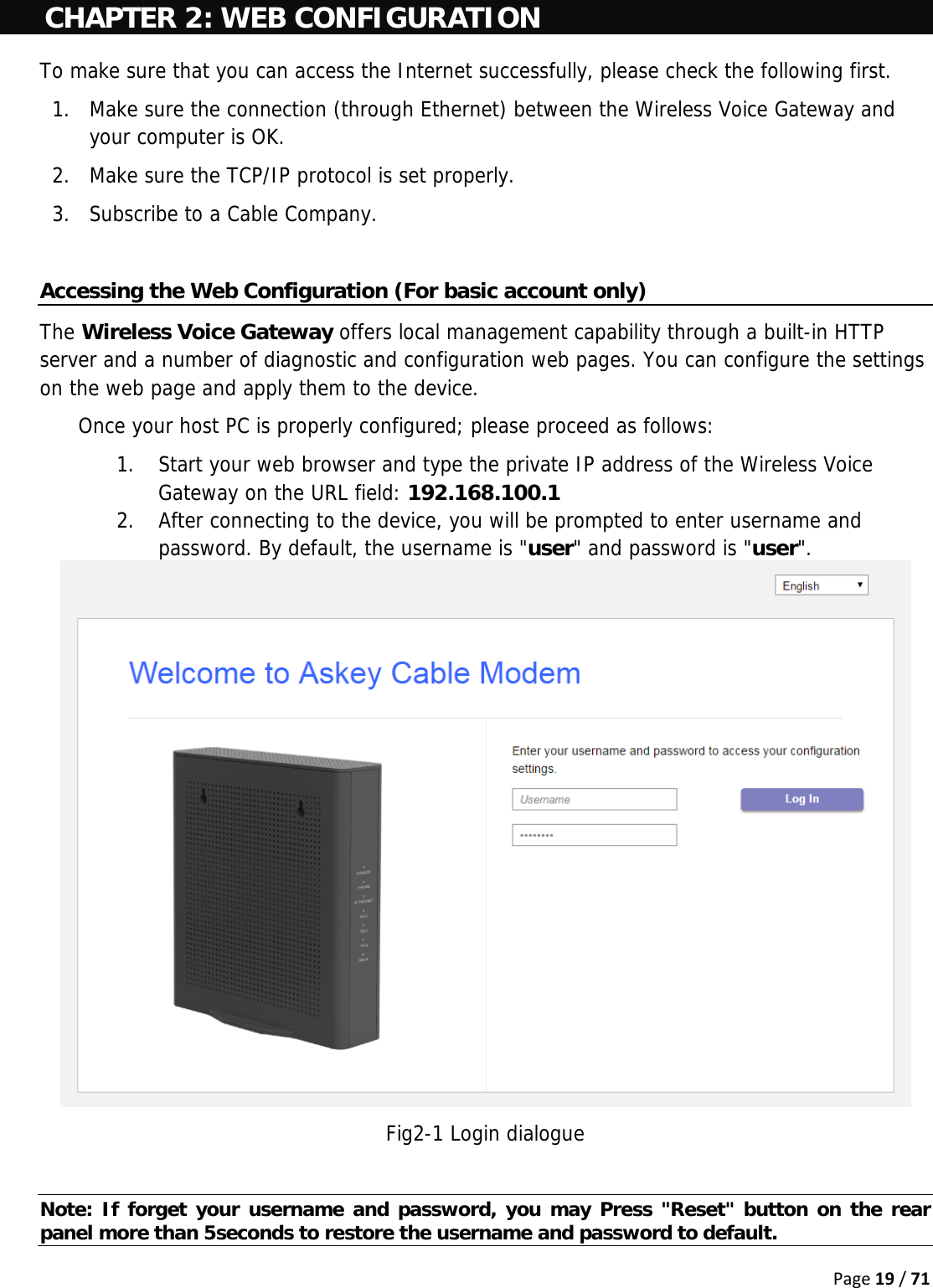
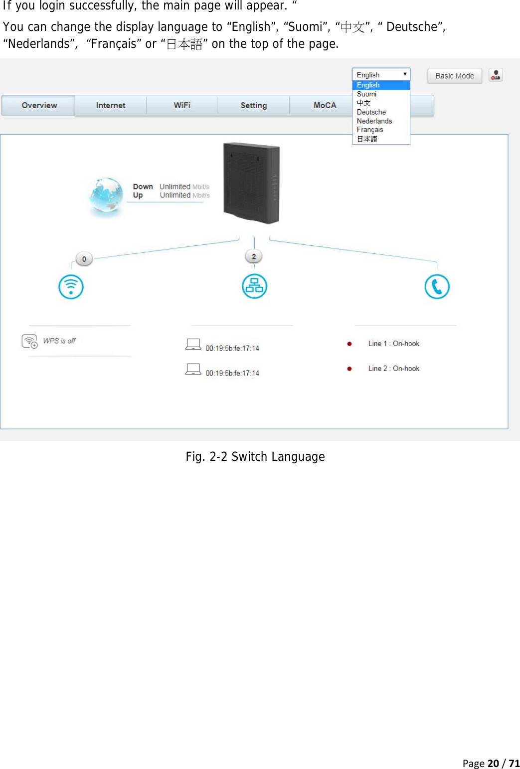
User Manual
2.
Users Manual_rev2.pdf
3.
Technical-User Manual_rev.1.pdf
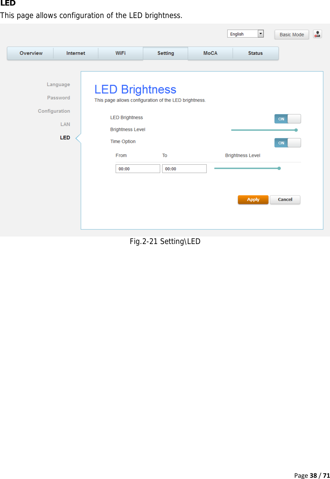
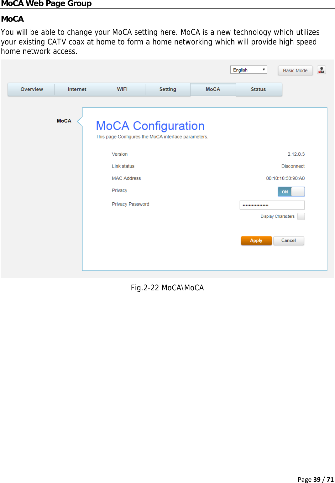
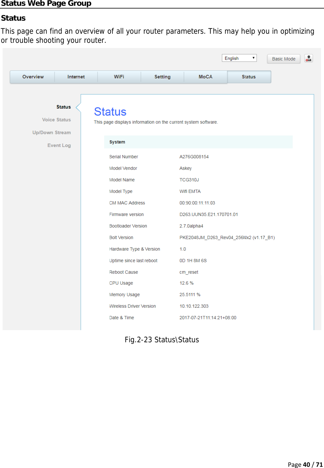
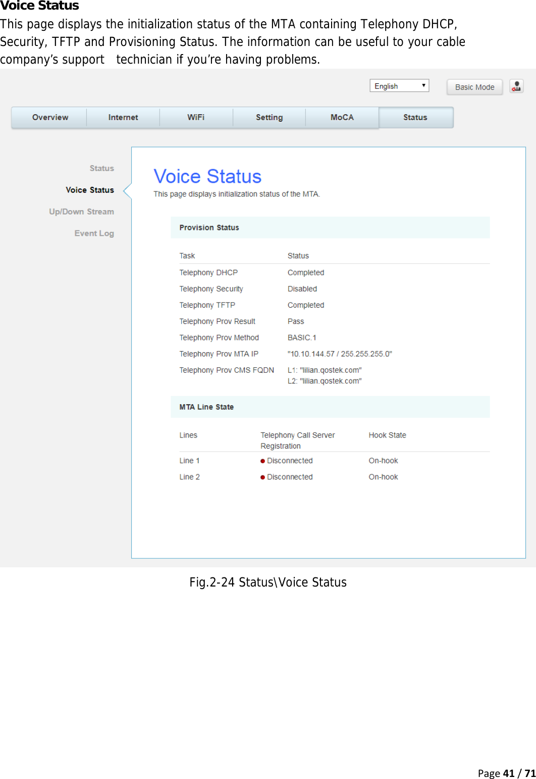
Users Manual_rev2.pdf
Navigation menu
Upload a User Manual
Namespaces
Wiki Guide
HTML
PDF
Info
Views
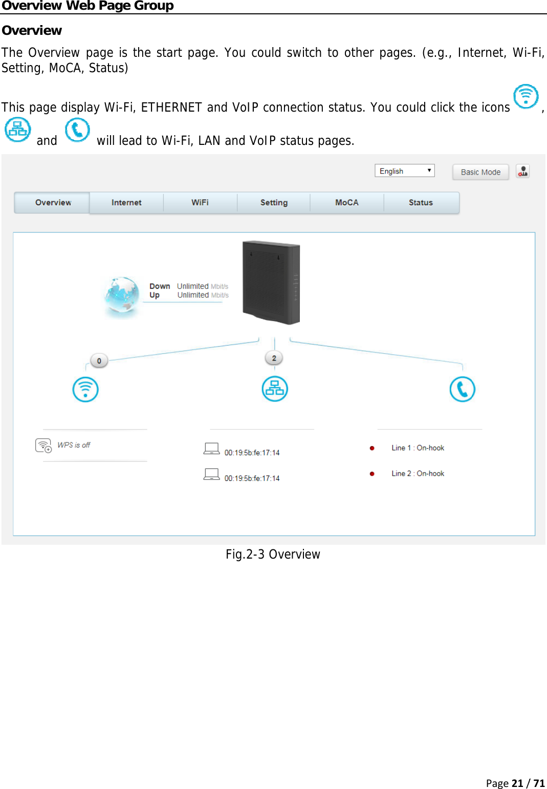
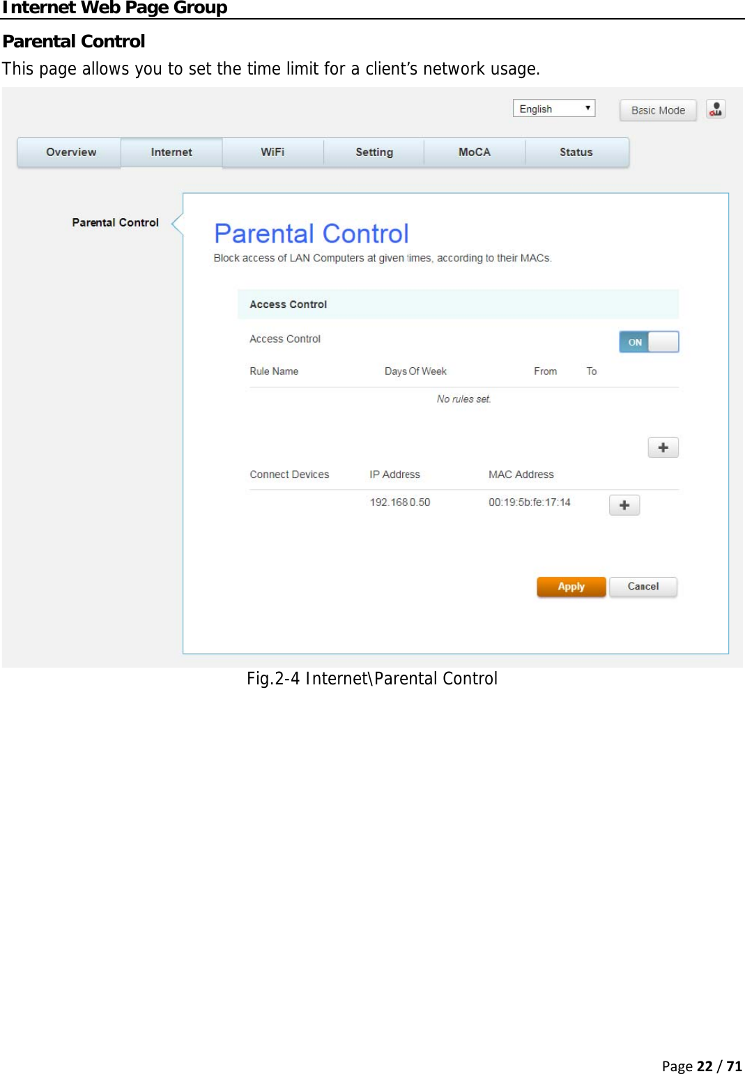
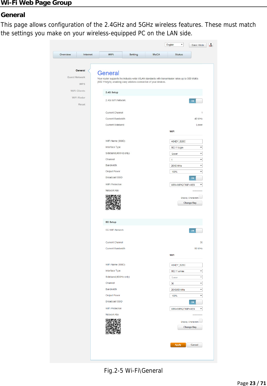
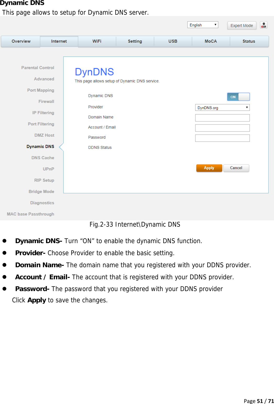
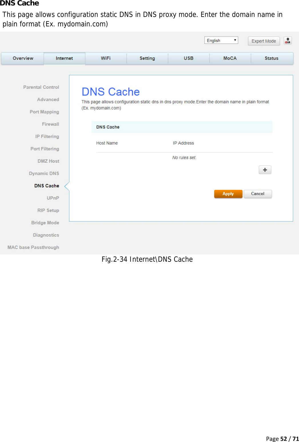
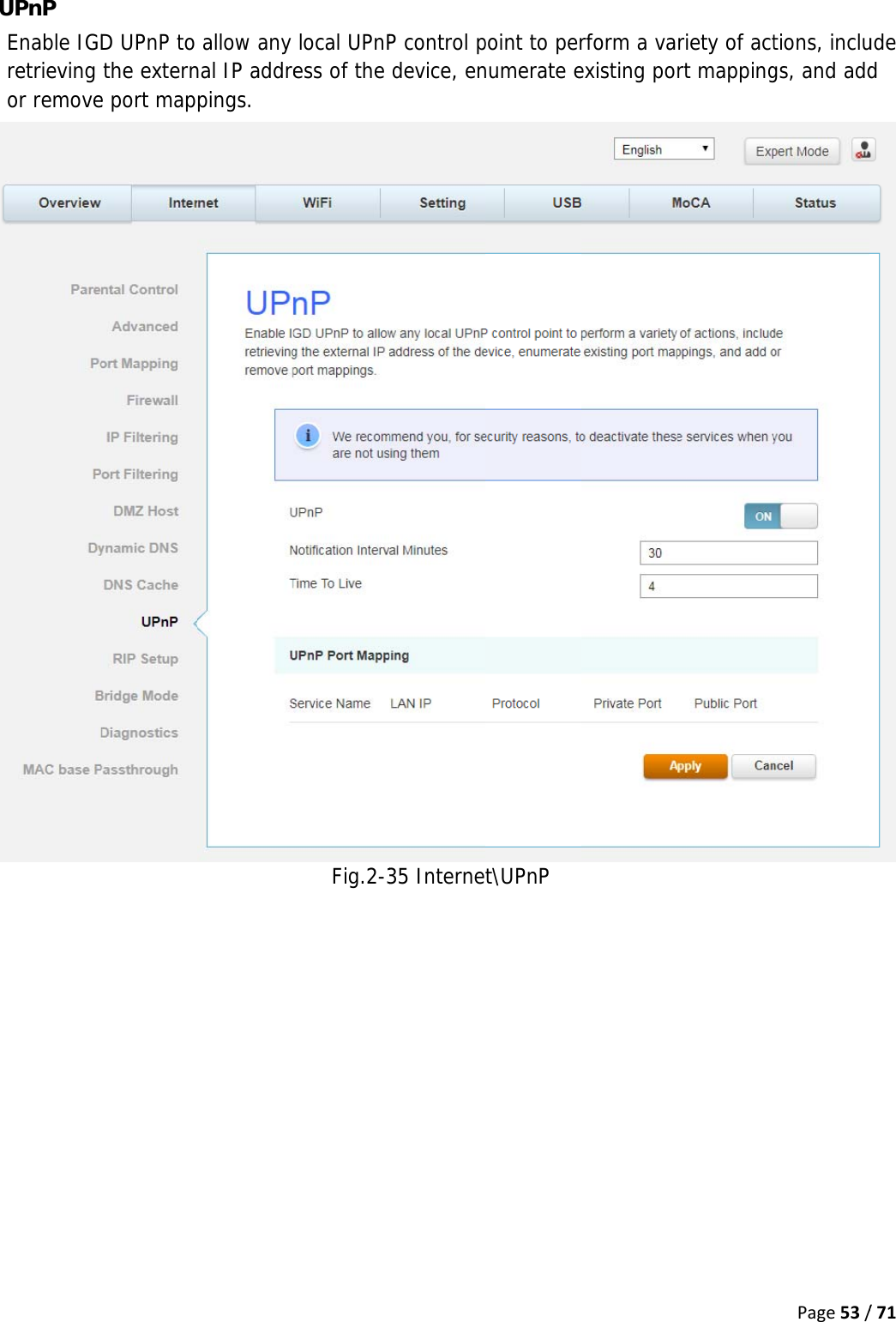
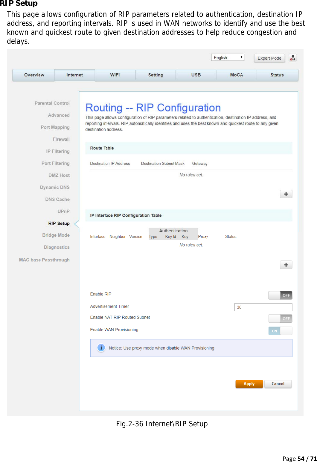
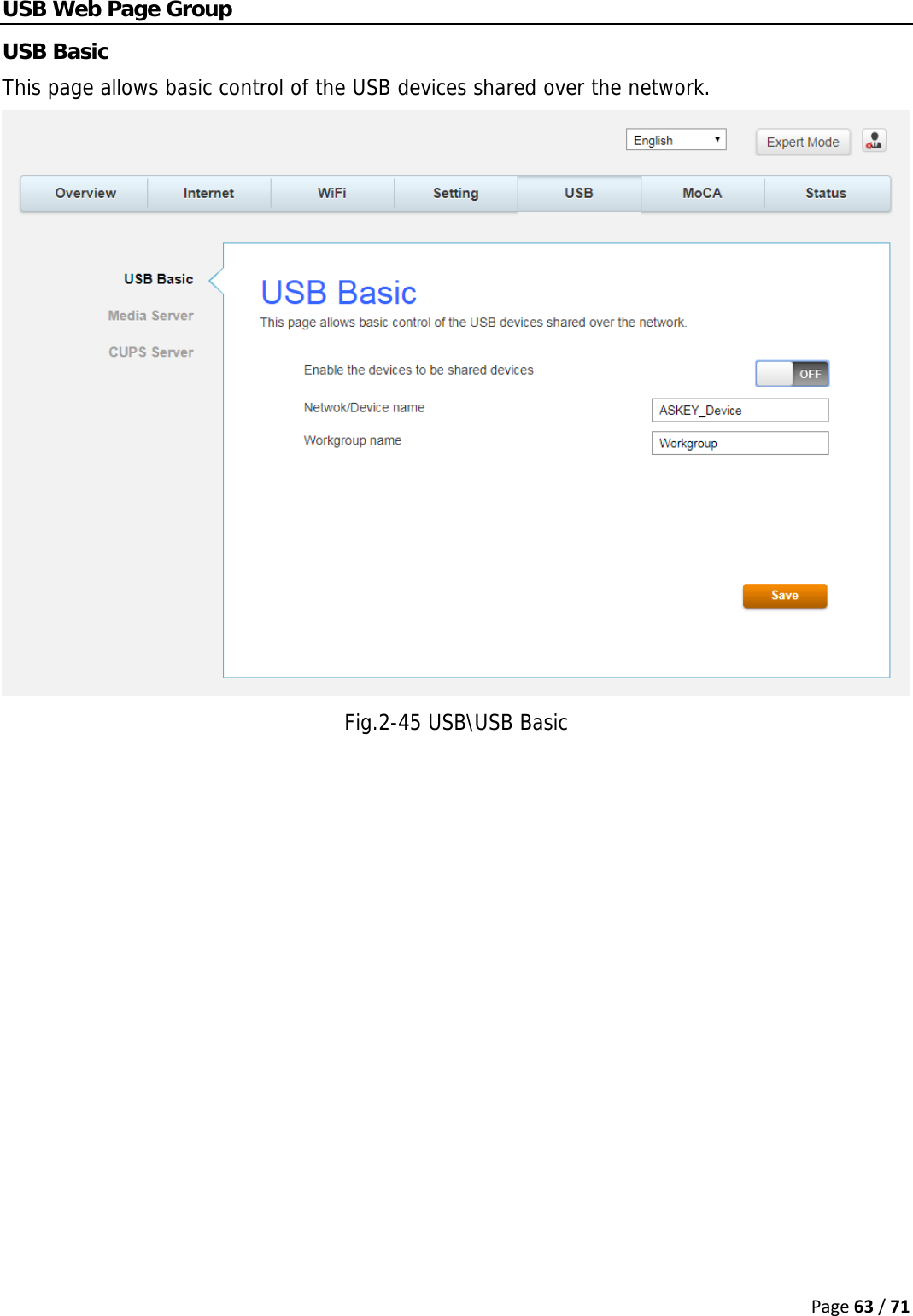
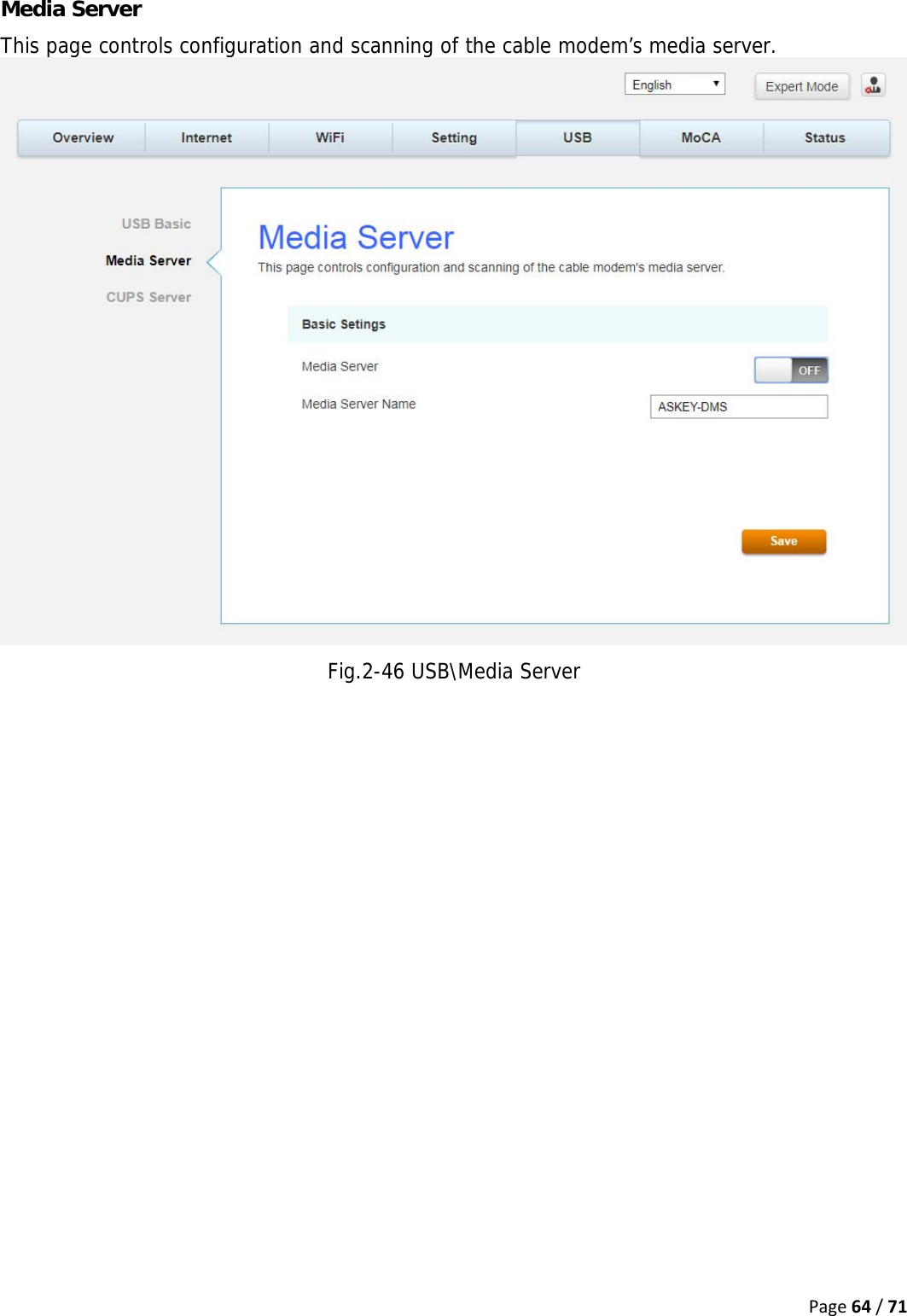
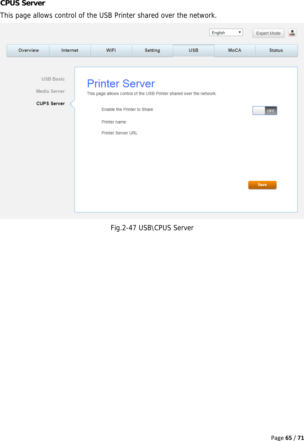
User Manual
Discussion / Help
Navigation