Askey Computer TCG310 Cable Modem User Manual rev2
Askey Computer Corp Cable Modem Users Manual rev2
Contents
- 1. User Manual
- 2. Users Manual_rev2.pdf
- 3. Technical-User Manual_rev.1.pdf
Users Manual_rev2.pdf
Page1/71
TCG310
USER MANUAL
Page2/71
SAFETY INSTRUCTIONS AND REGULATORY NOTICES ................................................................. 5
Chapter 1: Connections and Setup ......................................................................................................... 9
Cable Modem Overview .......................................................................................................... 9
Front Panel ........................................................................................................................ 9
Rear Panel ....................................................................................................................... 11
Bottom Side Panel for TEL ................................................................................................. 12
Wall Mounting .................................................................................................................. 13
Relationship among the Devices ............................................................................................. 14
What the Modem Does ...................................................................................................... 14
What the Modem Needs to Do Its Job ................................................................................. 14
Contact Your Local Cable Company ..................................................................................... 15
Connecting the Wireless Voice Gateway to a Single Computer .................................................... 15
Attaching the Cable TV Wire to the Wireless Voice Gateway ................................................... 16
Installation procedure for connecting to the Ethernet interface ............................................... 17
Telephone or Fax Connection ............................................................................................. 18
Chapter 2: WEB Configuration ............................................................................................................... 19
Accessing the Web Configuration (For basic account only) ......................................................... 19
Overview Web Page Group .................................................................................................... 21
Overview ......................................................................................................................... 21
Internet Web Page Group ...................................................................................................... 22
Parental Control ................................................................................................................ 22
Wi-Fi Web Page Group .......................................................................................................... 23
General ........................................................................................................................... 23
Guest Network ................................................................................................................. 27
WPS ................................................................................................................................ 31
Wi-Fi Clients ..................................................................................................................... 32
Reset .............................................................................................................................. 33
Settings Web Page Group ...................................................................................................... 34
Language ........................................................................................................................ 34
Password ......................................................................................................................... 35
Configuration ................................................................................................................... 36
LAN ................................................................................................................................ 37
Page3/71
LED ................................................................................................................................ 38
MoCA Web Page Group ......................................................................................................... 39
MoCA .............................................................................................................................. 39
Status Web Page Group ........................................................................................................ 40
Status ............................................................................................................................. 40
Voice Status ..................................................................................................................... 41
Up/Down Stream .............................................................................................................. 42
Event log ......................................................................................................................... 43
Accessing the Web Configuration (For admin account only) ....................................................... 44
Internet Web Page Group ...................................................................................................... 44
Advanced ........................................................................................................................ 44
Port Mapping ................................................................................................................... 46
Firewall ........................................................................................................................... 47
IP Filtering ....................................................................................................................... 48
Port Filtering .................................................................................................................... 49
DMZ Host ........................................................................................................................ 50
Dynamic DNS ................................................................................................................... 51
DNS Cache....................................................................................................................... 52
UPnP ............................................................................................................................... 53
RIP Setup ........................................................................................................................ 54
Bridge Mode ..................................................................................................................... 55
Diagnostic ........................................................................................................................ 56
MAC base Passthrough ...................................................................................................... 57
Wi-Fi Web Page Group .......................................................................................................... 58
Schedule ......................................................................................................................... 58
MAC Filter ........................................................................................................................ 59
WMM (Wi-Fi Multi-Media) ................................................................................................... 60
Settings Web Page Group ...................................................................................................... 61
Remote Access ................................................................................................................. 61
Internet Time ................................................................................................................... 62
USB Web Page Group ........................................................................................................... 63
Page4/71
USB Basic ........................................................................................................................ 63
Media Server .................................................................................................................... 64
CPUS Server ..................................................................................................................... 65
Chapter 3: Additional Information ........................................................................................................ 66
Frequently Asked Questions .................................................................................................. 66
General Troubleshooting ....................................................................................................... 67
Service Information .............................................................................................................. 68
Federal Communication Commission Interference Statement ..................................................... 69
CAUTION for UL (Check caution label on gift box) .................................................................... 71
Page5/71
SAFETY INSTRUCTIONS AND REGULATORY NOTICES
Product Safety Notice
Before installing or using the product, read these instructions carefully. Be sure to comply
strictly precautions.
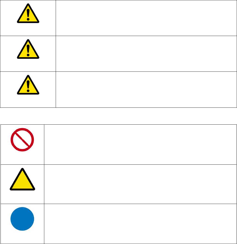
z Explanation of risk levels
DANGER
This indication is given where there is an immediate danger of death
or serious injury if the person in charge or any third party mishandles
the machine or does not avoid the dangerous situation when
operating or maintaining the machine.
WARNING
This indication is given where there is a potentiality for death or
serious injury if the person in charge or any third party mishandles
the machine or does not avoid the dangerous situation when
operating or maintaining the machine.
CAUTION
This indication is given where there is a danger of medium to minor
injury if the person in charge or any third party mishandles the
machine or does not avoid the dangerous situation when operating
or maintaining the machine.
z Explanation of pictorial warning indications and warning labels
Prohibited
It is used to prohibit its conduct in handling products.
Specific prohibited contents are indicated by pictures and sentences in or
near the figure symbol.
Caution
It is used to call attention to ignition, electric shock, high temperature,
etc. in the handling of products.
Specific notes content is indicated by a picture or sentence in or near the
figure symbol.
Instruction
Used to force actions based on instructions in the handling of products.
Specific instruction content is indicated by a picture or sentence in or near
the figure symbol.
Page6/71
z LIMITATIONS OF LIABILITY
This equipment has been designed for domestic use inside a building. In some
environments or circumstances, the use of wireless devices may be prohibited by
the owner of the building or responsible representatives of the organization. If in
doubt about the policy applying to the use of wireless devices in an organization
where a specific environment (e.g. airports), you should ask for permission to use
the device before turn it on. ASKEY assumes no liability for non-compliance with
regulations on the installation site, and radio interference created vis-à-vis third
parties and due to non-compliance with national regulations for this application.
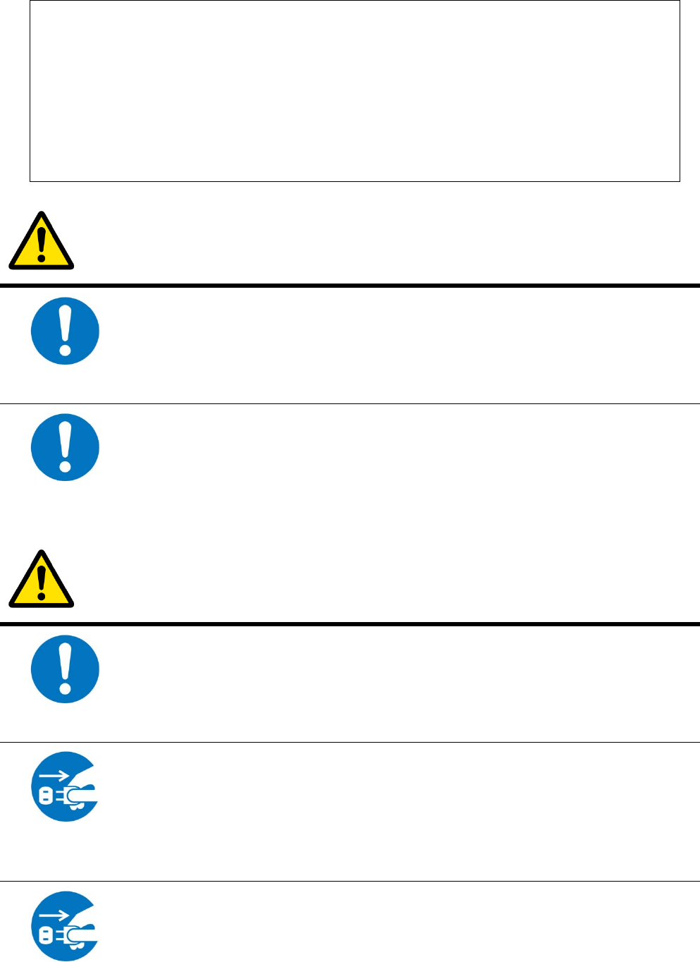
DANGER
Instruction
Do not overload wall outlet or extension cords as this may increase the
risk of electric shock or fire. If the power cord is frayed, replace it with a
new one.
Instruction
Do not attempt to connect with any computer accessory or electronic
product without instructions from qualified service personnel. This may
result in risk of electronic shock or fire.
WARNING
Instruction
Proper ventilation is necessary to prevent the product overheating. Do not
block or cover the slots and openings on the product, which are intended
for ventilation and proper operation.
Unplug the
power plug
When the product is expected to be not in use for a period of time,
unplug the power cord of the product to prevent it from the damage of
storm or sudden increases in rating.
Unplug the
Accidental penetrations of small metal objects (such as pins, paper clips,
etc.) disconnect the equipment from the mains as soon as possible (risk
of electric shock) and contact your Customer Service to find out how to
proceed. Do not reconnect the product as a foreign object has not been
eliminated. Unplug the product immediately if you notice it exudes a smell
Page7/71
power plug of burning or smoke. You should never open the unit yourself because
you could be electrocuted.
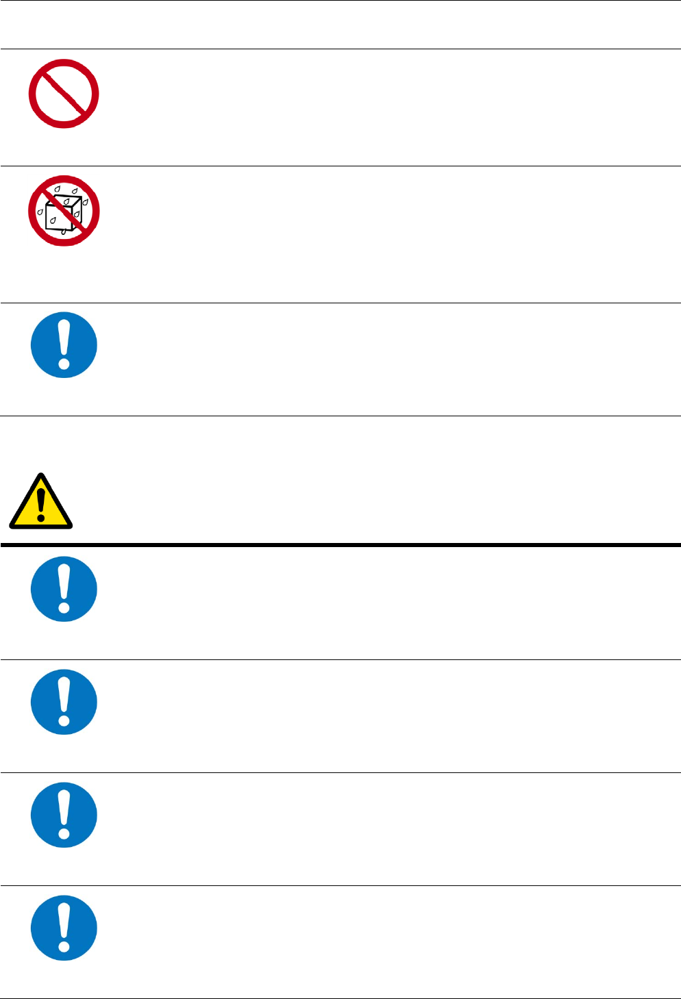
Prohibited
Do not place the product near any source of heat or expose it to direct
sunlight.
Water wet
prohibition
Do not expose the product to moisture. Never spill any liquid on the
product.
Instruction
Avoid connecting or using this product during a lightning storm.
Disturbances transmitted through the grid and / or telephone can cause
electric shock in the product and people.
CAUTION
Instruction
Use only power adapter supplied with the product. This appliance is
designed to operate in the rated voltage 110~240 VAC.
Instruction
Do not place this product on unstable stand or table.
Instruction
This product is designed for stationary use in an office or a room in the
home for a maximum ambient temperature of 40 ° C (104 ° F).
Instruction
To allow the disconnection of the device in case of problems, make sure
the base of the outlet you plug the power cord is easily accessible and is
located as close as possible to the equipment.
Page8/71
Instruction
Leave 7cm to 10cm around the appliance to ensure that proper
ventilation gets to it.
Be sure to
connect the
ground wire
The screen of the coaxial cable is intended to be connected to earth in
the building installation.
Disassembly
prohibited
Do not attempt to disassemble or open covers of this unit by yourself. Nor
should you attempt to service the product by yourself, which may void
the user’s authority to operate it. Contact qualified service personnel
under the following conditions:
1. If the power cord or plug is damaged or frayed.
2. If liquid has been spilled into the product.
3. If the product has been exposed to rain or water.
4. If the product does not operate normally when the operating
instructions are followed.
5. If the product has been dropped or the cabinet has been
damaged.
6. If the product exhibits a distinct change in performance.
7. If a cable is damaged or frayed provided.
8. If the unit is dropped or damaged in any way.
9. If there is a noticeable signs of overheating
Unplug the
power plug
Power off and unplug this product from the wall outlet when it is not in
use or before cleaning. Pay attention to the temperature of the power
adapter. The temperature might be high.
Instruction
Do not store the Cable Modem product in excessively hot, cold or damp
conditions. Operation Environmental:
‧ Operation Temperature: 5°C ~ 40°C
‧ Storage Temperature: -20°C ~ +70°C

Page9/71
CHAPTER 1: CONNECTIONS AND SETUP
Cable Modem Overview
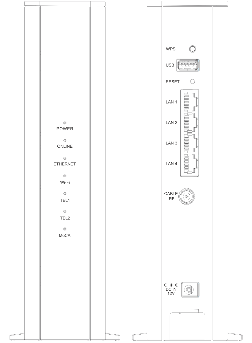
Front Panel
Fig. 1-1 Front Panel
POWER Indicates the power status.
ONLINE Displays the status of your cable connection. The light is off when no cable
connection is detected and fully lit when the modem has established a
connection with the network and data can be transferred.
ETHERNET Indicates the state of Ethernet ports.
Wi-Fi Indicates the traffic on the wireless network.
TEL
1 / 2 Indicates the status of the telephone ports.
MoCA Indicates the status of the MoCA functionality.

Page10/71
LED from top to bottom.
LED Status Description
POWER ON
OFF
The device is on.
The device boot fail or no power.
ONLINE
ON
OFF
FLASH
The device is ready for use. Now you can link to the internet.
The device is not link to the internet yet or not registration.
The device is in registration process or upgrade firmware.
ETHERNET
ON
OFF
FLASH
LAN port is connected to the PC.
LAN port is not connected to the PC.
Traffic on the LAN is working.
Wi-Fi
ON
OFF
FLASH
Wi-Fi is enabled.
Wi-Fi is disabled.
Wi-Fi traffic is working.
TEL 1 / 2
ON
OFF
FLASH
Phone is ready registration for use.
Phone is not able to use.
Phone interface is in registration process.
MoCA
ON
OFF
FLASH
MoCA is enabled.
MoCA is disabled.
MoCA traffic is working.
Table 1-1 LED behavior
Page11/71
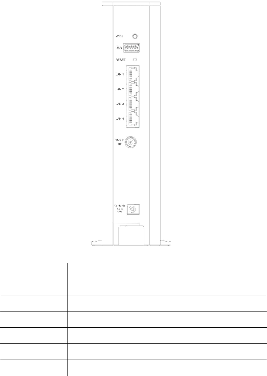
Rear Panel
Fig. 1-2 Rear Panel
Slot Description
WPS Enables scanning for available WPS client device
USB USB 3.0 host connector
RESET Reset/Reboot this Cable modem
LAN 1 / 2 / 3 / 4 Ethernet 10/100/1000 Base-T RJ-45 connector
CABLE RF F-Connector
12VDC 12V DC-IN Power connector.
Table 1-2 Rear Panel description
Page12/71
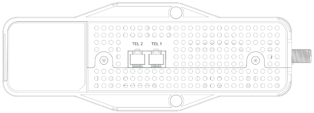
Bottom Side Panel for TEL
Fig. 1-3 Bottom Side Panel
The TEL 1 / 2 on the Bottom Side panel of TCG310, you can use telephony RJ-11
Connector.
Page13/71
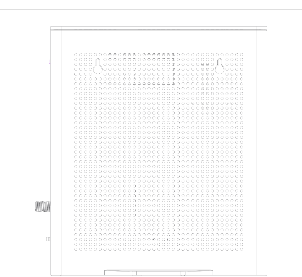
Wall Mounting
The number of the screw 2 pcs.
Direction for wall mounting: Tuner downward or leftward or rightward.
Dimension for the screw: diameter: 3.5 mm; length: 30 mm.
There are 2 slots on the side of the CABLE MODEM that can be used for wall mounting.
Note: When wall mounting the unit. Ensure that it is within reach of the power outlet.
Fig. 1-4 Wall Mounting
To do this:
1. For the cable modem, ensure that the wall you use is smooth, flat, dry and sturdy
and use the 2 screws holes.
2. The unit can be to use solid concrete wall and/or hard wood wall.
R
e
Th
P
a
W
Th
q
u
s
u
o
p
c
o
D
O
d
o
W
C
h
k
n
in
t
e
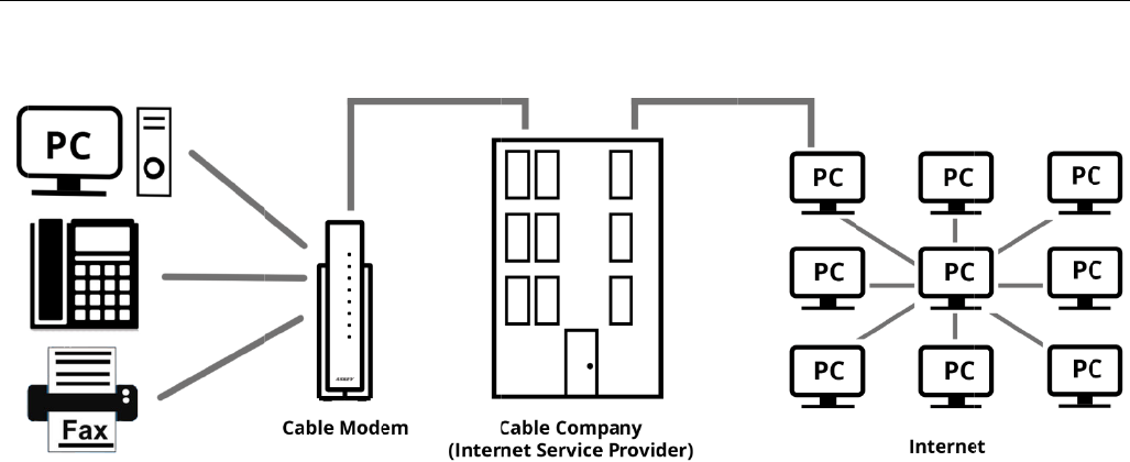
lationsh
h
is illustrat
a
cketCable
/
W
hat the
M
h
e Wireles
s
u
ality telep
u
bscribers
o
p
erate wit
h
o
mmunicat
O
CSIS/Eur
o
o
wnstream
W
hat the
M
The
R
servi
c
Pack
e
The
I
provi
d
(TSP)
acces
telep
h
T
elep
h
eck with
y
n
ow if you
t
ernet ser
v
ip amon
g
ion shows
/
Euro-Pac
k
M
odem D
o
s
Voice Ga
t
hone voic
e
o
n public
a
h
the Pack
e
ions. The
I
o
-DOCSIS
communi
c
M
odem N
e
R
i
g
ht Ca
b
c
es that us
e
tCable/Eu
I
nternet/
d
es you a
c
. The ISP
s Internet
h
ony acce
s
hone Net
w
y
our cable
need to in
v
ice work
f
g
the Dev
i
a cable c
o
k
etCable c
o
o
es
t
eway pro
v
e
and fax/
m
a
nd privat
e
e
tCable co
m
I
P traffic c
a
compliant
c
ations.
e
eds to D
b
le Comp
a
e cable
TV
ro-Packet
C
Telepho
n
c
cess to an
is your
g
a
t
content o
n
s
s to other
w
ork (PS
TN
company
t
stall speci
a
f
or you.
i
ces
o
mpany th
a
o
mpliant v
Fig. 1-5
C
v
ides hi
g
h
-
m
odem se
r
e
networks
m
pliant h
e
a
n transfe
r
head-end
o Its Job
a
ny: Mak
e
V
industry-
s
C
able com
p
n
y Servic
e
Internet
S
t
eway to t
h
n
the Worl
modems
o
N
).
t
o make s
u
a
l softwar
e
a
t offers
D
oice/data
s
C
onnectio
n
-
speed Int
e
r
vices ove
r
via an exi
e
ad-end eq
r
between
equipme
n
e
sure you
r
s
tandard
D
p
liant tech
n
e
Provide
r
S
ervice Pr
o
h
e Interne
t
d Wide W
e
o
r other t
e
u
re you ha
e
or re-con
D
OCSIS/Eu
r
s
ervices.
n
overview
e
rnet acce
r
residenti
a
stin
g
CAT
V
uipment a
the Wirel
e
n
t. The dat
a
r
local cabl
e
D
OCSIS/Eu
n
olo
g
y.
r
(ISP/T
S
o
vider (IS
P
t
and pro
v
e
b (WWW
)
e
lephony s
e
ve everyt
h
fi
g
ure you
r
o-DOCSI
S
ss as well
a
l, comme
r
V
infrastru
c
nd provid
e
e
ss Voice
G
a
security
e
compan
y
ro-DOCSI
S
S
P):
Y
our
c
P
) and Tel
e
v
ides you
w
)
. The TSP
e
rvices ov
e
h
in
g
you n
e
r compute
S
and
as cost-ef
f
r
cial, and
e
c
ture. It c
a
e
the IP-b
a
G
ateway a
n
secures u
p
y
provides
S
complia
n
c
able com
p
e
phony Se
r
w
ith a pipe
l
provides
y
e
r the Pub
l
e
ed to be
g
e
r to make
Page14
/
f
ective, tol
e
ducation
a
n inter-
a
sed voice
n
d
p
stream a
n
data
n
t and
p
any
r
vice Provi
d
l
ine to
y
ou with
l
ic Switche
g
in; they’ll
your cabl
e
/
71
l-
n
d
d
er
d
e

Page15/71
Contact Your Local Cable Company
You will need to contact your cable company to establish an Internet account before you can
use your gateway. You should have the following information ready (which you will find on the
sticker on the gateway):
• The serial number
• The model number
• The Cable Modem (CM) Media Access Control (MAC) address
• The Terminal Adapter (EMTA) MAC address
• Security information: Service Set Identifier (SSID), Encryption key / passphrase
(WPA2-PSK by default), channel number. Default values are indicated underneath the
modem on the sticker.
Please check the following with the cable company
The cable service to your home supports DOCSIS/Euro-DOCSIS compliant two-way
modem access.
Your internet account has been set up. (The Media Terminal Adapter will provide data
service if the cable account is set up but no telephony service is available.)
You have a cable outlet near your PC and it is ready for Cable Modem service.
Note: It is important to supply power to the modem at all times. Keeping your modem plugged
in will keep it connected to the Internet. This means that it will always be ready whenever you
need.
Important Information
Your cable company should always be consulted before installing a new cable outlet. Do not
attempt any rewiring without contacting your cable company first.
Please verify the following on the Wireless Voice Gateway
The Power LED should be lighted when plug-in the power supply.
Connecting the Wireless Voice Gateway to a Single Computer
This section of the manual explains how to connect your Wireless Voice Gateway to the
Ethernet port on your computer and install the necessary software. Please refer to Figure 1-7
to help you connect your Digital Cable Modem for the best possible connection.
Page16/71
Attaching the Cable TV Wire to the Wireless Voice Gateway
1. Locate the Cable TV wire. You may find it one of three ways:
a. Connected directly to a TV, a Cable TV converter box, or VCR. The line will be
connected to the jack, which should be labeled either IN, CABLE IN, CATV, CATV IN,
etc.
b. Connected to a wall-mounted cable outlet.
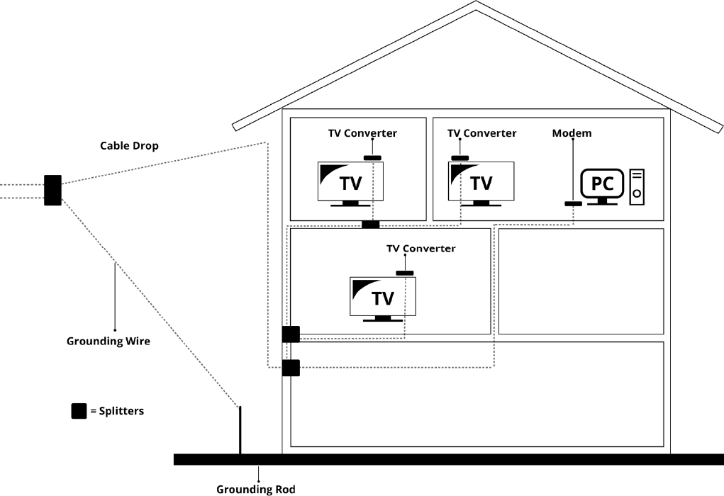
c. Coming out from under a baseboard heater or other location. See Figure 1-6 for the
wiring example.
Notes: For optimum performance, be sure to connect your Wireless Voice Gateway to the first point
the cable enters your home. The splitter must be rated for at least 1GHz.
Fig. 1-6 Basic Home Wiring
Page17/71
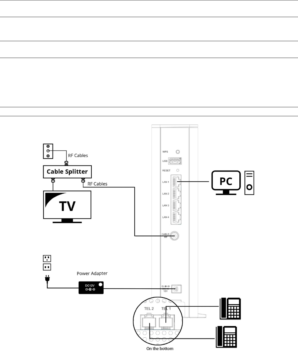
Installation procedure for connecting to the Ethernet interface
Follow these steps for proper installation. (Please refer to Fig. 1-7)
Plug the coaxial cable to the cable wall outlet and the other end to the modem’s cable
connector.
Note: To ensure a fast registration of the modem, the coaxial cable must be connected to
the modem before it is powered on.
Plug the power adapter into the socket of the cable modem and two-pin plug in the AC outlet to
power on the modem.
Note: Only use the power adapter that comes with the modem. Using another power
adapter can cause damage to the product, and will void the warranty.
Connect an Ethernet cable (direct connection, see below) to the Ethernet port at the back of
the computer, and the other end to the ETHERNET port on the rear panel of the cable modem.
The modem will seek the appropriate cable signal on the cable television network and go
through the initial registration process on its own. The modem is ready for data transfer after
the green LED "ONLINE" is lit continuously.
Note: the button "RESET" at the back of the modem is used primarily for maintenance.
Fig. 1-7 Connect to the Modem
Page18/71
Telephone or Fax Connection
When properly connected, most telephony devices can be used with the Wireless Voice
Gateway
just as with a conventional telephone service. To make a normal telephone call, pick
up the handset; listen for a dial tone, then dial the desired number. For services such as call
waiting, use the hook switch (or FLASH button) to change calls. The following procedures
describe some of the possible connection schemes for using telephony devices with the
Wireless Voice Gateway.
1. Connect a standard phone line cord directly from the phone (fax machine, answering
machine, caller ID box, etc.) to one of the TEL jacks on the
Wireless Voice Gateway.
2. If there is a phone line in your home which is NOT connected to another telephone service
provider, connect a standard phone line cord from a jack on this line to one of the TEL jacks
of the Wireless Voice Gateway. Connect a standard phone line cord directly from the phone
(fax machine, answering machine, caller ID box, etc.) to one of the other jacks in the house
that uses that line.
3. If you have a multi-line telephone, connect a standard phone line cord (not an RJ-14 type
line cord) from the phone to the TEL jacks on the Wireless Voice Gateway. (Other phones
can be added to each line by using standard phone line splitters.)
Page19/71
CHAPTER 2: WEB CONFIGURATION
To make sure that you can access the Internet successfully, please check the following first.
1. Make sure the connection (through Ethernet) between the Wireless Voice Gateway and
your computer is OK.
2. Make sure the TCP/IP protocol is set properly.
3. Subscribe to a Cable Company.
Accessing the Web Configuration (For basic account only)
The Wireless Voice Gateway offers local management capability through a built-in HTTP
server and a number of diagnostic and configuration web pages. You can configure the settings
on the web page and apply them to the device.
Once your host PC is properly configured; please proceed as follows:
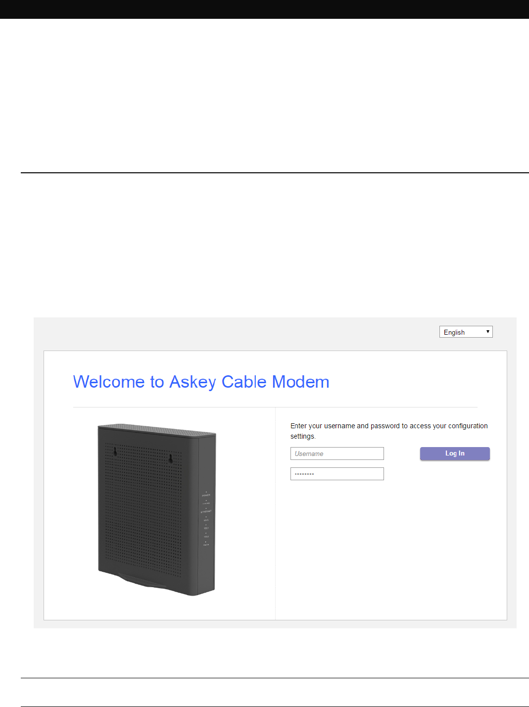
1. Start your web browser and type the private IP address of the Wireless Voice
Gateway on the URL field: 192.168.100.1
2. After connecting to the device, you will be prompted to enter username and
password. By default, the username is "user" and password is "user".
Fig2-1 Login dialogue
Note: If forget your username and password, you may Press "Reset" button on the rear
panel more than 5seconds to restore the username and password to default.
Page20/71
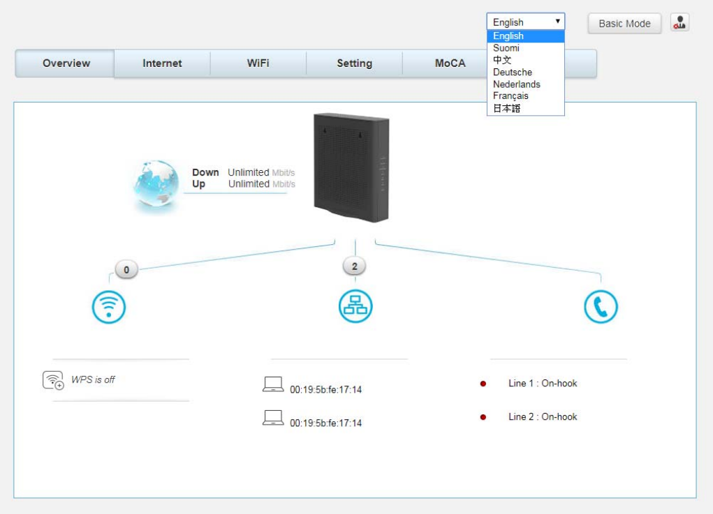
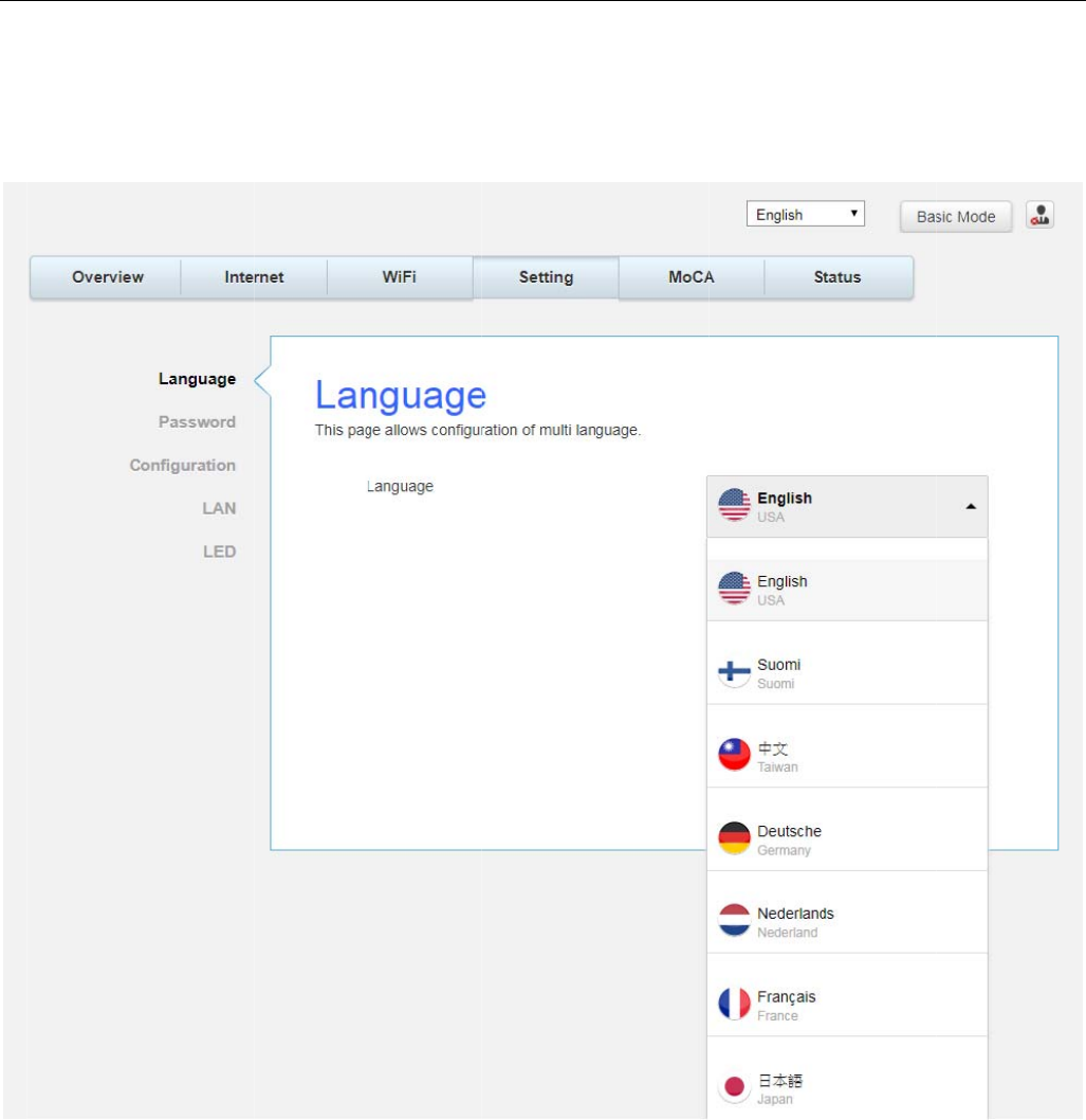
If you login successfully, the main page will appear. “
You can change the display language to “English”, “Suomi”, “中文”, “ Deutsche”,
“Nederlands”, “Français” or “日本語” on the top of the page.
Fig. 2-2 Switch Language
O
v
O
v
Th
S
e
Th
v
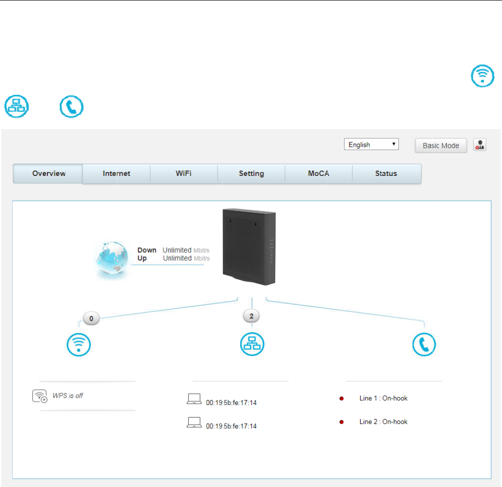
erview
W
v
erview
h
e Overvie
e
ttin
g
, Mo
C
h
is pa
g
e di
and
W
eb Pa
ge
w pa
g
e is
C
A, Status
)
splay Wi-
F
will l
e
e
Group
the start
)
F
i, ETHER
N
e
ad to Wi-
F
pa
g
e. Yo
u
N
ET and V
o
F
i, LAN an
d
Fi
g
u
could s
w
o
IP conne
c
d
VoIP sta
t
.2-3 Over
v
w
itch to ot
h
c
tion statu
s
t
us pages.
v
iew
h
er pa
g
es
.
s
. You co
u
.
(e.
g
., In
t
u
ld click th
e
Page21
/
t
ernet, Wi
-
e
icons
/
71
-
Fi,
,
I
n
P
a
Th
n
ternet
W
a
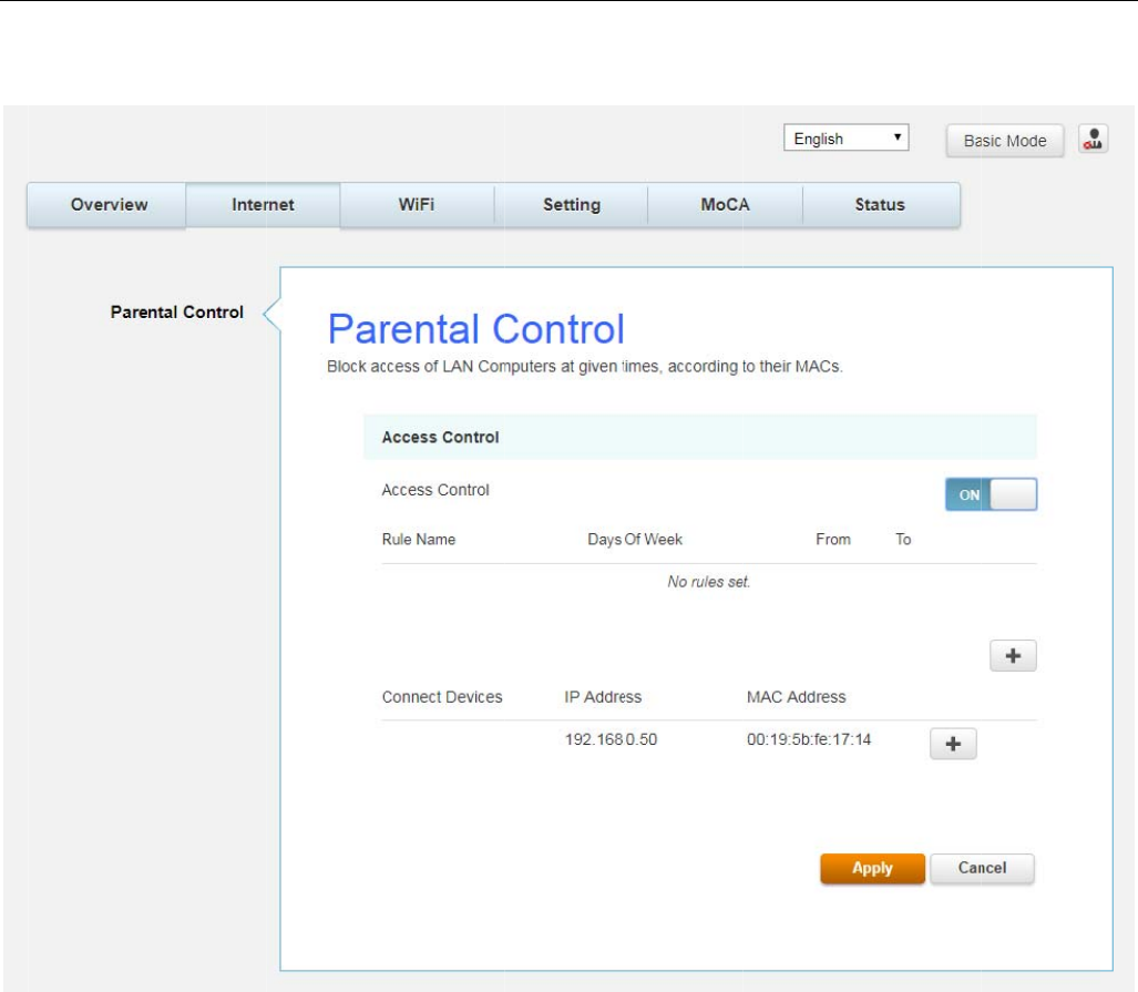
rental C
o
h
is pa
g
e al
W
eb Pa
g
e
G
o
ntrol
lows you t
G
roup
o set the
t
F
t
ime limit f
o
F
i
g
.2-4 Int
e
o
r a client
’
e
rnet\Pare
’
s network
ntal Contr
o
usa
g
e.
o
l
Page22
/
/
71
W
G
e
Th
th
e
W
i-Fi Web
e
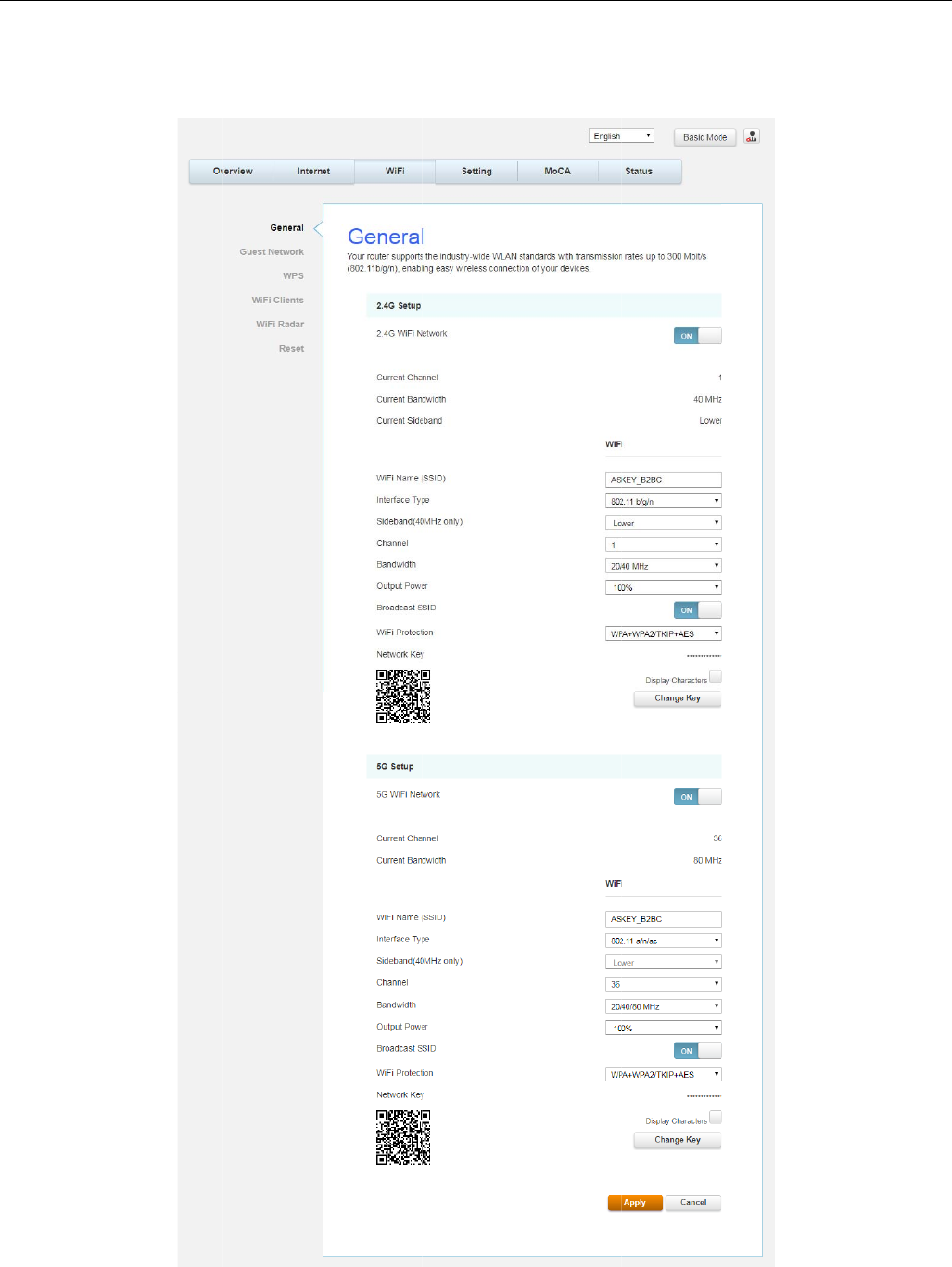
neral
h
is pa
g
e al
e
settin
g
s
Pa
g
e Gr
o
lows confi
g
you make
o
up
g
uration o
f
on your
w
f
the 2.4G
H
w
ireless-eq
u
Fig.2
-
H
z and 5G
u
ipped PC
-
5 Wi-Fi\G
e
Hz wireles
s
on the LA
N
e
neral
s
features
.
N
side.
.
T
hese m
u
Page23
/
u
st match
/
71
Page24/71
z 2.4GWi-Fi Network / 5GWi-Fi Network: It may help you to Enable or Disable the
2.4GHz / 5GHz wireless function.
z Current Channel: The channel that you choose will be displayed in this field.
z Current Bandwidth: The bandwidth that you choose will be displayed in this field.
z Current Sideband: The sideband that you choose will be displayed in this field.
z Wi-Fi Name (SSID): The SSID for 2.4GHz / 5GHz wireless function.
z Interface Type: There are three different modes can be selected. 2.4GHz can be
selected 802.11b/g, 802.11b/g/n and 802.11n only; 5GHz can be selected 802.11a,
802.11a/n/ac and 802.11n/ac only.
z Sideband (40MHz only): There is “Lower” and “Upper” can be selected if Bandwidth
40 MHz was enabled.
z Channel: In 802.11 Band 2.4GHz, there are 1 to 11 channels. In 802.11 Band 5GHz,
there are 36, 40, 44, 48, 52, 56, 60, 64, 149, 153, 157, 161 channels. Choose the one
that is suitable for this device.
z The 5.25-5.35GHz and 5.47-5.725GHz DFS bands are not available for USA marketing models
z Bandwidth: Select wireless channel width 20/40 MHz is for 2.4GHz Wi-Fi default value,
and 20/40/80 MHz is for 5GHz Wi-Fi default value. (Bandwidth taken by wireless
signals of this access point.)
z Output Power: This setting decides the output power of this device. You may use it to
economize on electricity by selecting lower percentage of power output. Control the
range of the AP by adjusting the radio output power.
z Broadcast SSID: Broadcasting the SSID causes the name of your network to appear in
the list of available networks.
z Wi-Fi Protection: The method of Wi-Fi protection can be OFF, WPA, WPA2/AES or
WPA+WPA2/TKIP+AES.
z Network key: The network key is the password that you use to authenticate with your
router.
z QR Code: Use QR code scanning APP on the smartphone to get Wi-Fi Name (SSID), Wi-
Fi Protection and Network key.
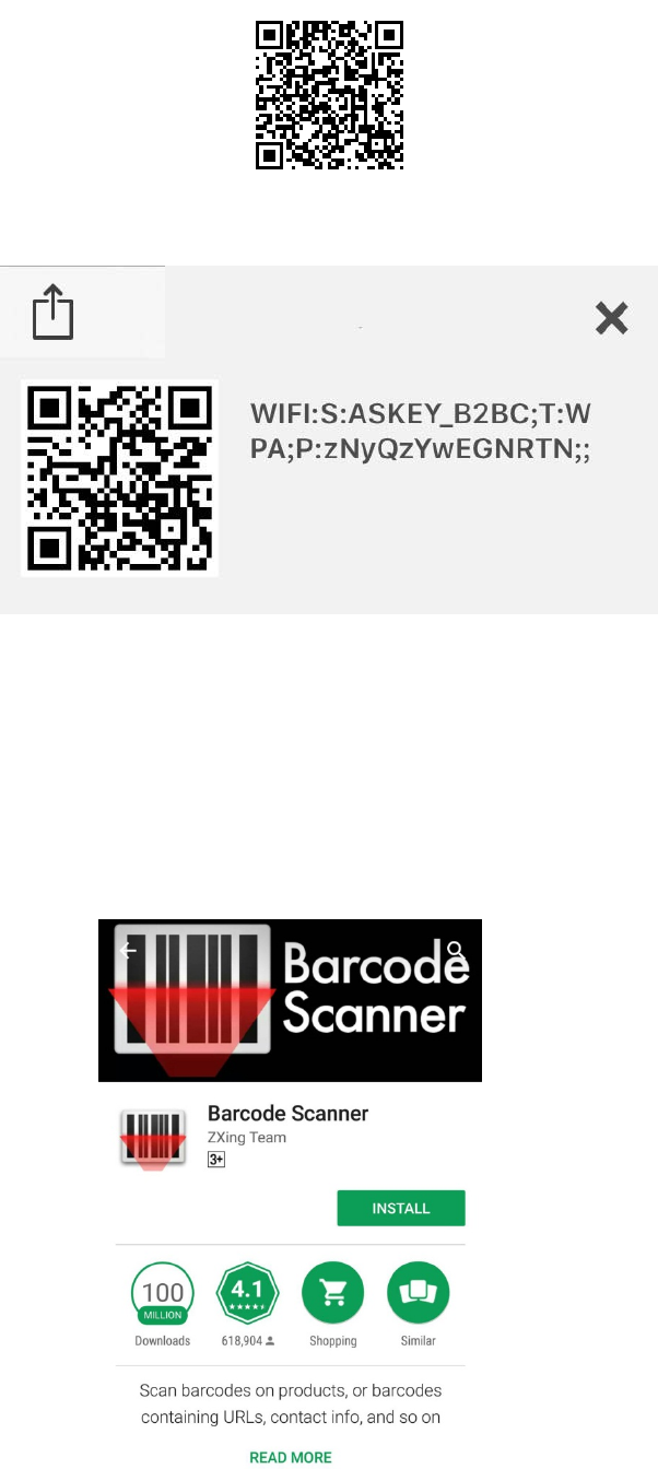
Page25/71
Fig.2-6 Wi-Fi\General\QR Code
Fig.2-7 Wi-Fi\General\Scanning result
z WIFI: S (SSID): ASKEY_B2BC
z T (Wi-Fi Protection): WPA
z P (Network key): zNyQzYwEGNRTN
For Android users, you can install “Barcode Scanner“ app to scan Wi-Fi QR code, and the smart
phone will be able to connect automatically without entering the SSID and password.
Fig.2-8 Wi-Fi\General\Android APP

Page26/71
802.11x Authentication introduction
If you enable the 802.11x authentication function, you will have to offer the following
information-
z WPA (Wi-Fi Protected Access)/WPA2:
It must be used in conjunction with an authentication server such as RADIUS to
provide centralized access control and management. It can provide stronger
encryption and authentication solution than none WPA modes. WPA2 is the second
generation of WPA security.
z WPA/WPA2 Encryption:
There are two types that you can choose, AES, TKIP+AES.
TKIP takes the original master key only as a starting point and derives its
encryption keys mathematically from this mater key. Then it regularly changes
and rotates the encryption keys so that the same encryption key will never be
used twice
AES provides security between client workstations operating in ad hoc mode. It
uses a mathematical ciphering algorithm that employs variable key sizes of 128,
192 or 256 bits.
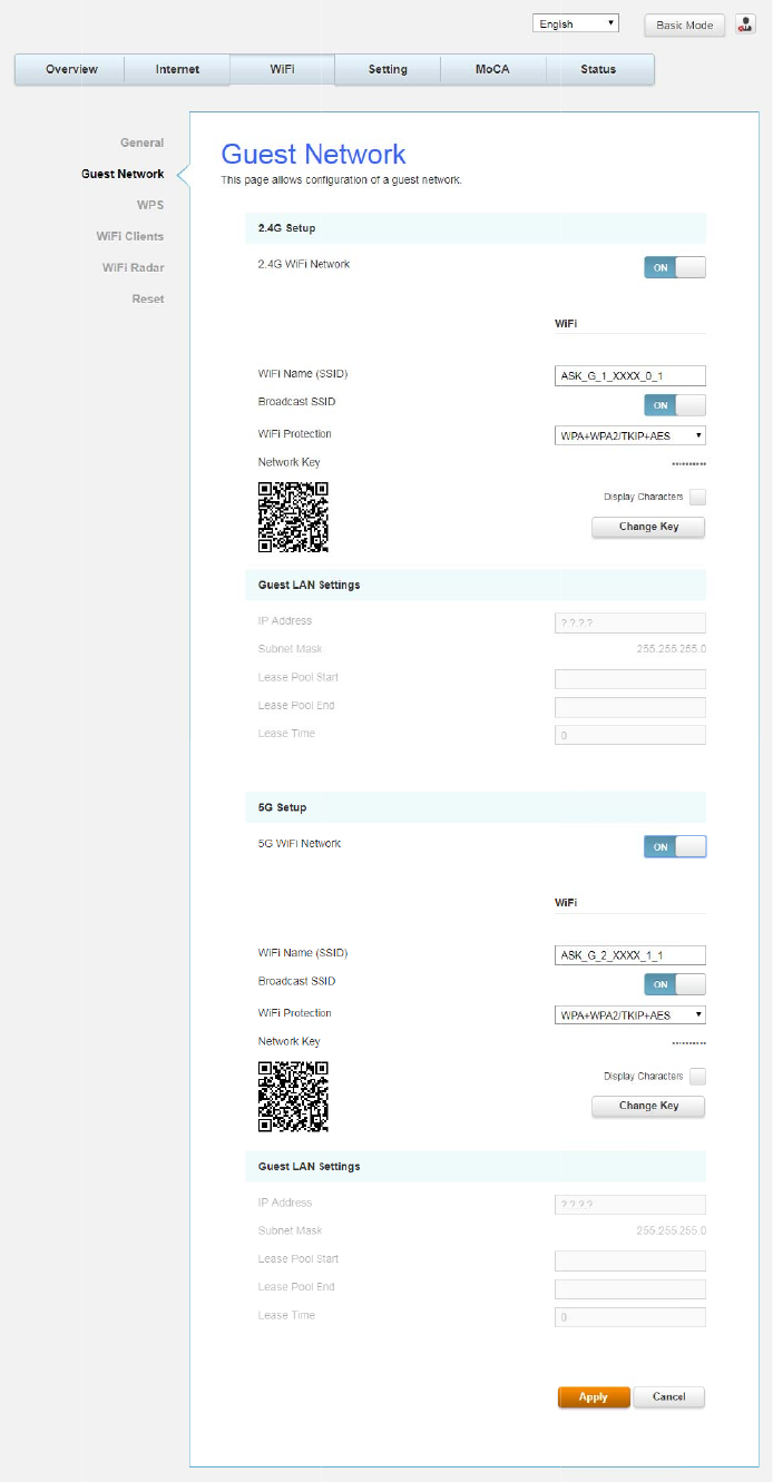
G
u
Th
u
est Net
w
h
is pa
g
e al
w
ork
lows confi
g
g
uration o
f
f
the 2.4G
H
Fig.2-9
W
H
z and 5G
W
i-Fi\Gues
t
Hz
g
uest
n
t
Network
n
etwork.
Page27
/
/
71
Page28/71
z 2.4G Wi-Fi Network / 5G Wi-Fi Network: It may help you to Enable or Disable the
2.4GHz / 5GHz wireless function.
z Wi-Fi Name (SSID): The SSID for 2.4GHz / 5GHz Guest wireless function.
z Broadcast SSID: Broadcasting the SSID causes the name of your network to appear in
the list of available networks.
z Wi-Fi Protection: The method of Wi-Fi protection can be OFF, WPA, WPA2/AES or
WPA+WPA2/TKIP+AES.
z Network key: The network key is the password that you use to authenticate with your
router.
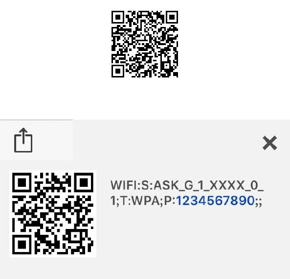
z QR Code: Use QR code scanning APP on the smartphone to get Wi-Fi Name (SSID), Wi-
Fi Protection and Network key.
Fig.2-10 Wi-Fi\General\QR Code
Fig.2-11 Wi-Fi\General\Scanning result
z WIFI: S (SSID): ASK_G_1_XXXX_0_1
z T (Wi-Fi Protection): WPA
z P (Network key): 1234567890

Page29/71
For Android users, you can install “Barcode Scanner“ app to scan Wi-Fi QR code, and the smart
phone will be able to connect automatically without entering the SSID and password.
Fig.2-12 Wi-Fi\General\Android APP
Guest LAN Settings
A private IP address and Subnet Mask for LAN sub netting.
For example 192.168.0.1./ 255.255.255.0.
z Configure the IP address numbers for the DHCP server with “Lease pool start” and
“Lease pool end”.
z Configure the IP address lease time with “Lease time” for DHCP server.

Page30/71
802.11x Authentication introduction
If you enable the 802.11x authentication function, you will have to offer the following
information-
z WPA (Wi-Fi Protected Access)/WPA2:
It must be used in conjunction with an authentication server such as RADIUS to
provide centralized access control and management. It can provide stronger
encryption and authentication solution than none WPA modes. WPA2 is the second
generation of WPA security.
z WPA/WPA2 Encryption:
There are two types that you can choose, AES, TKIP+AES.
TKIP takes the original master key only as a starting point and derives its
encryption keys mathematically from this mater key. Then it regularly changes
and rotates the encryption keys so that the same encryption key will never be
used twice
AES provides security between client workstations operating in ad hoc mode. It
uses a mathematical ciphering algorithm that employs variable key sizes of 128,
192 or 256 bits.
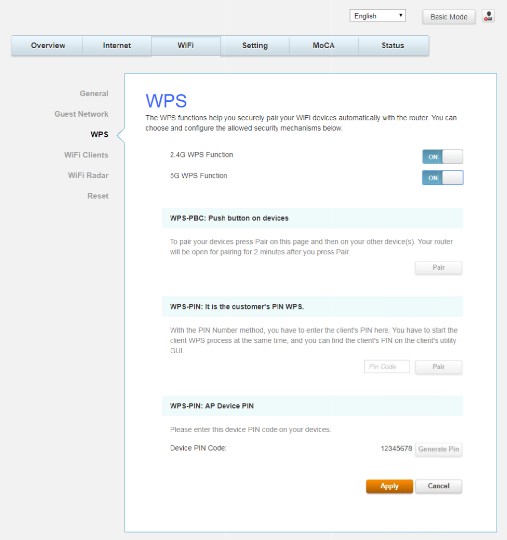
W
Th
of
A
c
N
e
se
t
W
PS
h
is page all
o
configurin
g
c
cess Point
(
e
twork via
W
t
tings on b
o
o
ws you to
c
g
and conn
e
(
AP), and y
o
W
PS, messa
o
th devices.
c
onfigure
W
e
cting your
W
o
ur PC (or
W
ges are ex
c
W
PS setting.
W
ireless ac
c
W
ireless De
v
c
hanged be
t
Fig.
2
Wi-Fi Prot
e
c
ess point.
I
v
ice) is call
e
t
ween the
S
2
-13 Wi-Fi
\
e
cted Setup
T
I
n this case
e
d the STA.
S
TA and AP
\
WPS
T
M
(WPS) is
, the Wirel
e
When con
f
in order to
an easy an
e
ss Voice G
a
f
iguring yo
u
configure t
h
Page31
/
d secure
w
a
teway
is t
h
u
r
Wireless
h
e
securit
y
/
71
w
ay
h
e
y
W
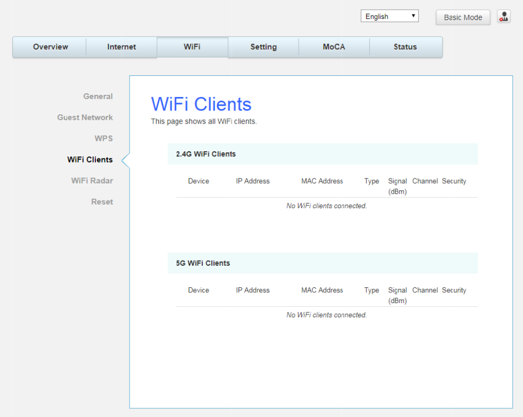
Th
W
i-Fi Clien
h
is pa
g
e s
h
ts
h
ows all Wi-Fi clients
.
Fig.2-14 Wi-Fi\Wi-
Fi Clients
Page32
/
/
71
Page33/71
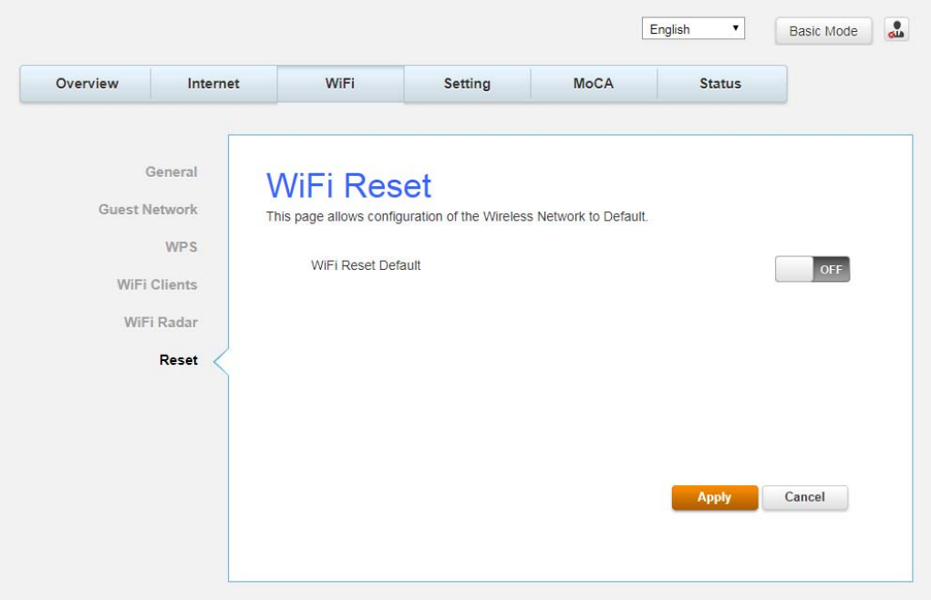
Reset
This page allows configuration of the wireless network to default.
Fig.2-16 Wi-Fi\Reset
S
e
L
a
Th
Yo
“F
e
ttin
g
s
W
a
n
g
ua
g
e
h
is pa
g
e al
o
u can cha
ran
ç
ais” o
r
W
eb Pa
g
e
G
lows confi
g
n
g
e the di
s
r
“日本語”
G
roup
g
uration o
f
s
play lan
gu
on the to
p
f
lan
g
uag
e
u
a
g
e to “
E
p
of the p
a
Fig.2-1
7
e
.
E
n
g
lish
”
, “
S
ag
e.
7
Setting\L
S
uomi”, “
中
an
g
ua
g
e
中文
”, “ De
u
u
tsche”, “
N
Page34
/
N
ederlands
/
71
”
,
Page35/71
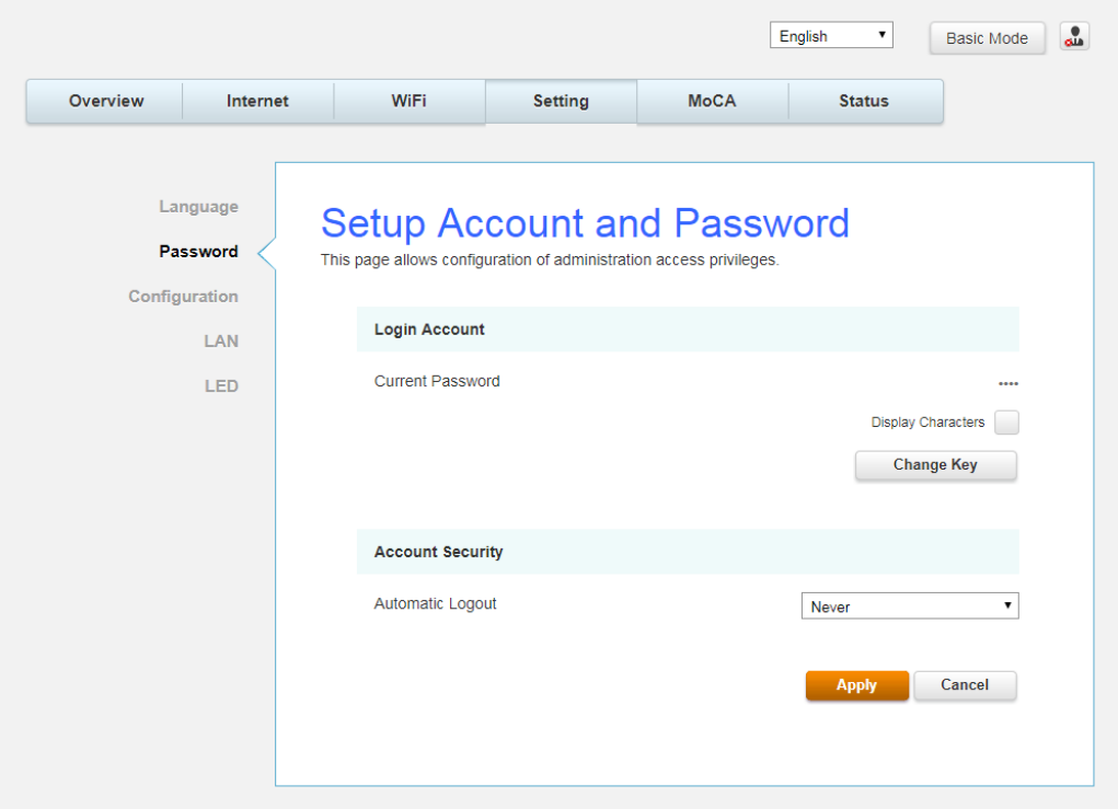
Password
By default, the username is "user" and password is "user".
When the current password is the default one, the user is strongly encouraged to change the
default web password.
The password can be a minimum of 8 characters, maximum of 20 characters and is case
sensitive. If forget your username and password, you may Press "Reset" button on the rear
panel more than 5seconds to restore the username and password to default.
Note: We are always suggesting you to modify the password. This is a basic protection against
wrongful access to the Gateway Web pages.
Fig.2-18 Setting\Password
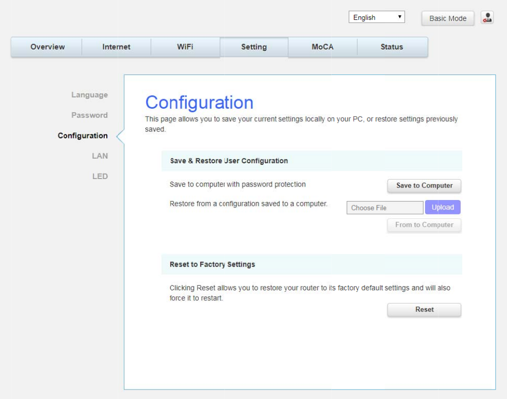
C
o
Th
pr
z
z
o
nfi
g
urat
i
h
is pa
g
e al
eviously s
a
Save
&
to Co
m
T
o rest
o
the file
(
Comp
u
Reset
t
default
s
i
on
lows you t
a
ved.
&
Restore
m
puter an
d
o
re a previ
o
(
usually b
a
u
ter to res
t
t
o Factor
y
s
ettin
g
s a
n
o save yo
u
User Co
n
d
follow th
o
us confi
g
a
ckupsetti
n
t
ore the s
e
y
Settin
gs
n
d will als
o
u
r current
s
Fig.2-19
S
n
fi
g
uratio
n
e prompts
uration, cl
ng
s.con
f
.)
e
ttin
g
s. On
s
: Click R
e
o
force it t
o
s
ettin
g
s lo
c
S
etting\Co
n
n
:
T
o bac
k
.
ick Uploa
d
Once the
f
ce the set
t
e
se
t
allow
s
o
restart.
c
ally on y
o
n
fi
g
uratio
n
k
up the c
u
d
and use
f
ile has be
e
t
in
g
s are r
e
s
you to re
o
ur PC, or
r
n
u
rrent con
f
the navi
ga
e
n located
,
e
stored, t
h
store your
r
estore se
t
f
i
g
uration,
a
tion wind
o
,
click Fro
m
h
e device
w
router to
Page36
/
t
tin
g
s
click Sav
e
o
w to loca
t
m
to
w
ill reboot
.
factory
/
71
e
t
e
.
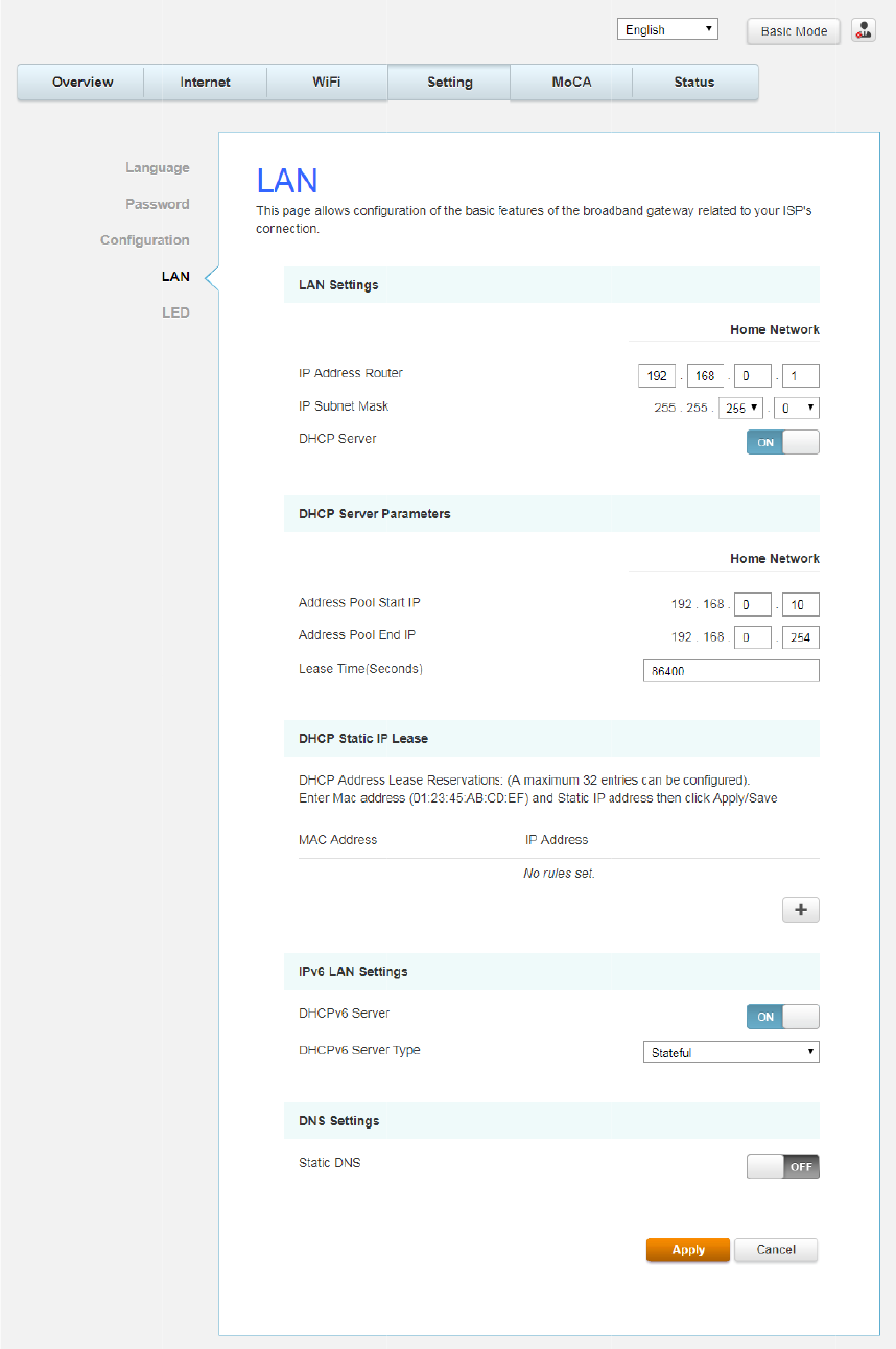
L
A
Th
IS
A
N
h
is pa
g
e al
P’s conne
c
lows confi
g
c
tion.
g
uration o
f
f
the basic
Fig.2
features
o
-20 Settin
g
o
f the bro
a
g
\LAN
a
dband
g
a
t
t
eway rela
t
Page37
/
t
ed to you
r
/
71
r
Page38/71
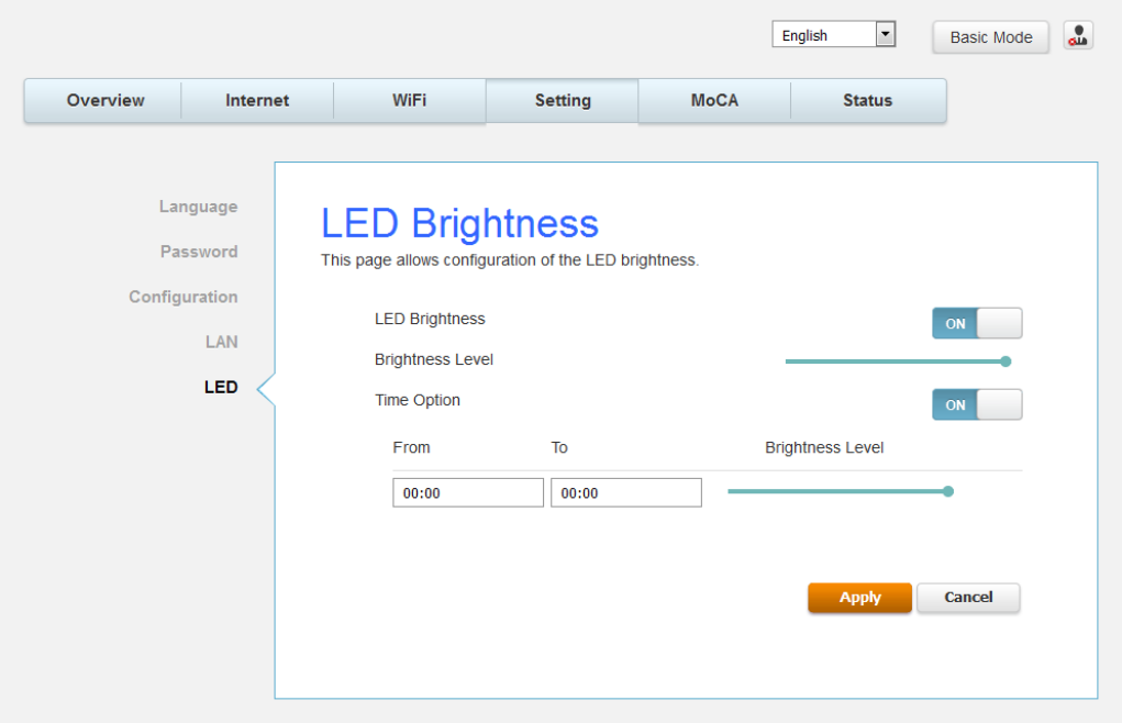
LED
This page allows configuration of the LED brightness.
Fig.2-21 Setting\LED
Page39/71
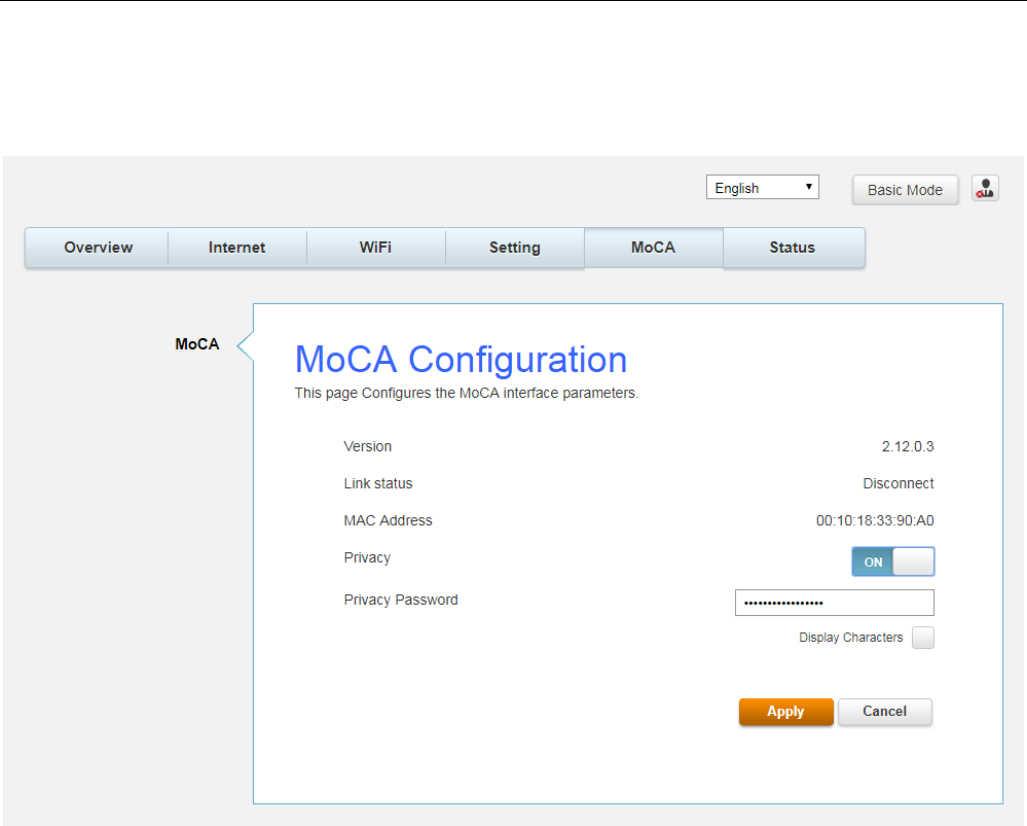
MoCA Web Page Group
MoCA
You will be able to change your MoCA setting here. MoCA is a new technology which utilizes
your existing CATV coax at home to form a home networking which will provide high speed
home network access.
Fig.2-22 MoCA\MoCA
S
t
S
t
Th
or
t
atus We
b
t
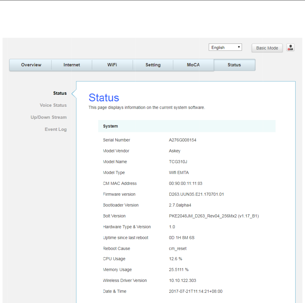
atus
h
is pa
g
e c
a
trouble s
h
b
Pa
g
e G
r
a
n find an
o
h
ootin
g
yo
u
r
oup
o
verview
o
u
r router.
o
f all your
Fig.2-
router par
a
23 Status
\
a
meters.
T
\
Status
T
his may help you in
Page40
/
optimizin
g
/
71
g
V
o
Th
S
e
c
o
o
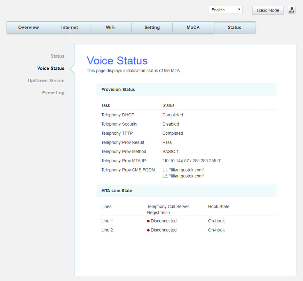
ice Stat
u
h
is pa
g
e di
e
curity,
T
F
T
o
mpany’s s
u
s
splays the
T
P and Pr
o
upport t
e
initializati
o
o
visionin
g
S
e
chnician i
f
o
n status
o
S
tatus. Th
e
f
you’re h
a
Fig.2-24
o
f the MT
A
e
informat
a
vin
g
probl
Status\Vo
i
A
containin
g
ion can b
e
ems.
i
ce Status
g
Telepho
n
e
useful to
n
y DHCP,
your cabl
e
Page41
/
e
/
71
U
p
Th
u
s
B
y
th
e
p
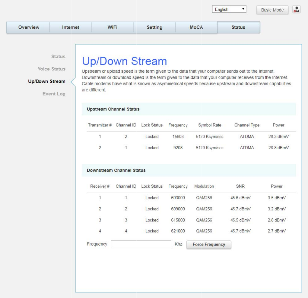
/Down
S
h
is pa
g
e r
e
s
eful to yo
u
y
enterin
g
d
e
CM locki
S
tream
e
ports curr
e
u
r cable c
o
d
ownstrea
n
g
to the
s
e
nt CM’s u
o
mpany’s
s
m freque
n
s
pecified f
r
Fi
pstream
/
s
upport te
c
n
cy in KHz
r
equency.
g
. 2-25 St
a
downstre
a
c
hnician if
y
and clicki
n
a
tus\ Up
/D
a
m inform
a
y
ou’re ha
v
ng
“Force
f
D
own Stre
a
a
tion. The
v
in
g
proble
f
requency”
a
m
informati
o
ms.
button, y
o
Page42
/
o
n can be
o
u can for
c
/
71
c
e
Page43/71
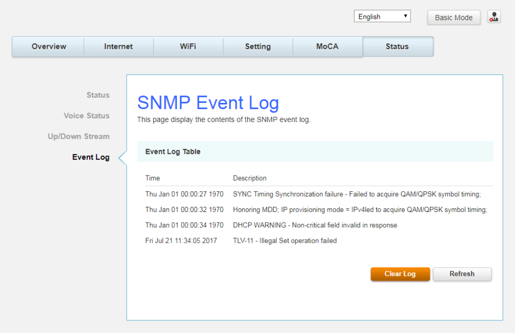
Event log
This page displays the contents of the SNMP event log.
Fig. 2-26 Status\Event log
Page44/71
Accessing the Web Configuration (For admin account only)
Once your host PC is properly configured; please proceed as follows:
1. Start your web browser and type the private IP address of the Wireless Gateway
on the URL field: 192.168.100.1
2. After connecting to the device, you will be prompted to enter username and
password. By default, the username is "admin" and password is "admin".
This section that introduces the admin account addition pages, and the same as
the basic mode pages refer to page 20 ~ 45, please.
Internet Web Page Group
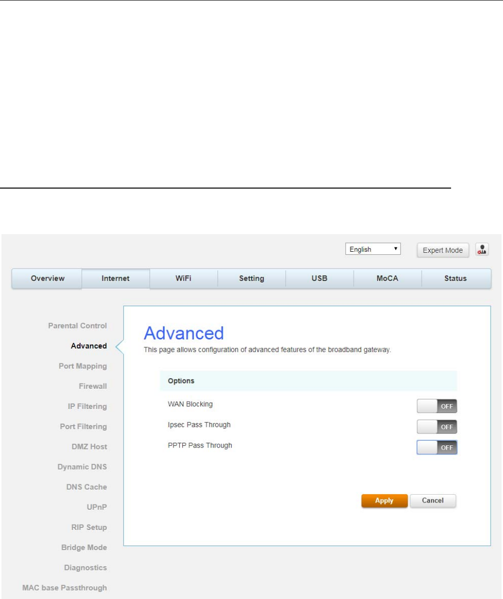
Advanced
This page allows you to configuration of advanced features of the broadband Gateway.
Fig.2-27 Internet\Advanced
Page45/71
z WAN Blocking prevents others on the WAN side from being able to ping your gateway.
With WAN Blocking enabled, your gateway will not respond to pings it receives, effectively
“hiding” your gateway.
z Ipsec PassThrough enables IpSec type packets to pass WAN Ù LAN. IpSec (IP Security)
is a security mechanism used in Virtual Private Networks (VPNs).
z PPTP PassThrough enables PPTP type packets to pass WAN Ù LAN. PPTP (Point to Point
Tunneling Protocol) is another mechanism sometimes used in VPNs.
P
z
z
P
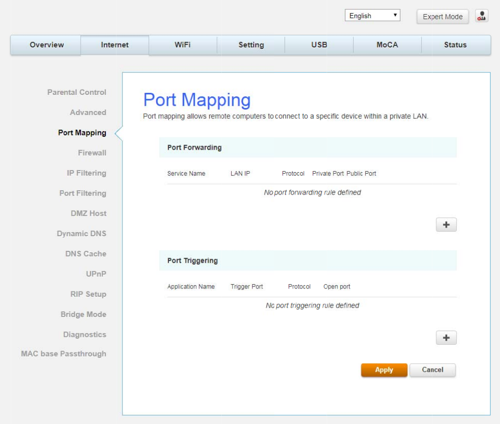
ort Map
p
T
his pa
g
e
Port F
o
to ori
g
i
n
to ori
g
i
n
outside
r
connec
t
you sp
e
Port T
r
the WA
N
g
ame p
l
work fo
r
p
in
g
allows co
n
o
rwardin
g
n
ate an IP
n
ate a con
n
r
s. Howev
e
t
ion to a p
a
e
cify.
r
i
gg
erin
g
N
side of
y
l
ayin
g
PC
o
r
you, eac
h
n
fi
g
uration
g
For LAN
connectio
n
n
ection on
e
r, someti
m
a
rticular P
C
Some Int
e
y
our
g
ate
w
o
n the LA
N
h
time you
of Port F
o
Fig.2-28 I
n
Ù WAN c
o
n
with a P
C
to your P
C
m
es you m
C
on your
L
e
rnet activi
w
ay be abl
e
N
side. Por
t
play the
g
o
rwardin
g
a
n
ternet\P
o
o
mmunica
t
C
on the
W
C
. This pro
t
ay wish f
o
L
AN if the
ties, such
e
to ori
g
in
a
t
tri
gg
erin
g
g
ame.
a
nd Port
T
o
rt Mappin
g
t
ions, the
g
W
AN; it will
t
ects you
f
o
r anyone
o
destinatio
n
as interac
t
a
te connec
t
g
is an ele
g
T
ri
gg
erin
g
.
g
g
ateway n
o
i
g
nore at
t
f
rom malic
i
o
utside to
n
port (ap
p
t
ive
g
amin
g
t
ions duri
n
g
ant mech
o
rmally on
t
empts of
t
i
ous attac
k
be able to
p
lication)
m
g
, require
ng
the
g
a
m
anism tha
t
Page46
/
ly allows
y
t
he WAN
P
k
s from
ori
g
inate
a
m
atches o
n
that a PC
o
m
e with yo
u
t
does this
/
71
y
ou
P
C
a
n
e
o
n
u
r
Page47/71
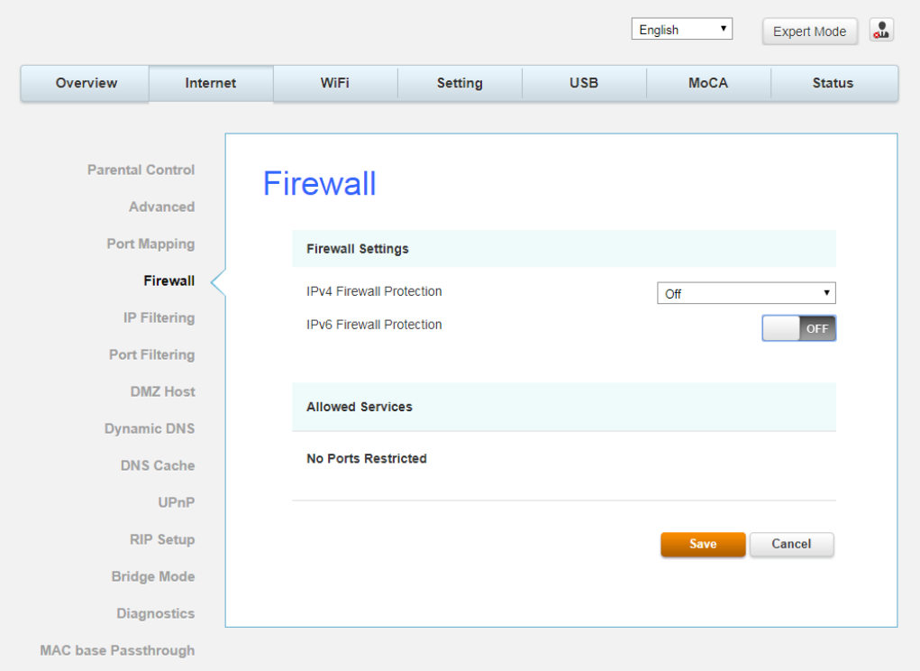
Firewall
This page allows you to enable/disable, and you can choose “Off”, “Low”, “Medium”, “High”
firewall protection.
The Low setting does not block any services/ports, however it does protect against invalid
packets and well known attacks. The Medium setting will cause the firewall to drop a packet
unless it is on a specific port of allowed services. The High setting is similar to medium, but
allows access to even fewer services. The Off setting allows all traffic to pass.
Fig.2-29 Internet\Firewall
Page48/71
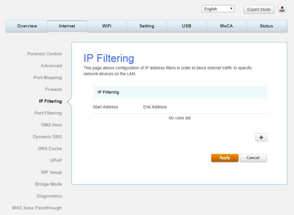
IP Filtering
This page enables you to enter the IP address ranges of PCs on your LAN that you don’t want
to have outbound access to the WAN. These PCs can still communicate with each other on
your LAN, but packets they send to WAN addresses are blocked by the gateway.
Fig.2-30 Internet\IP Filtering
Page49/71
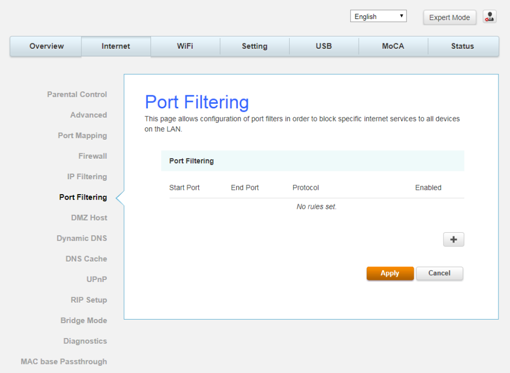
Port Filtering
This page enables you to enter the IP address ranges of PCs on your LAN that you don’t want
to have outbound access to the WAN. These PCs can still communicate with each other on
your LAN, but packets they send to WAN addresses are blocked by the gateway.
Fig.2-31 Internet\IP Filtering
D
D
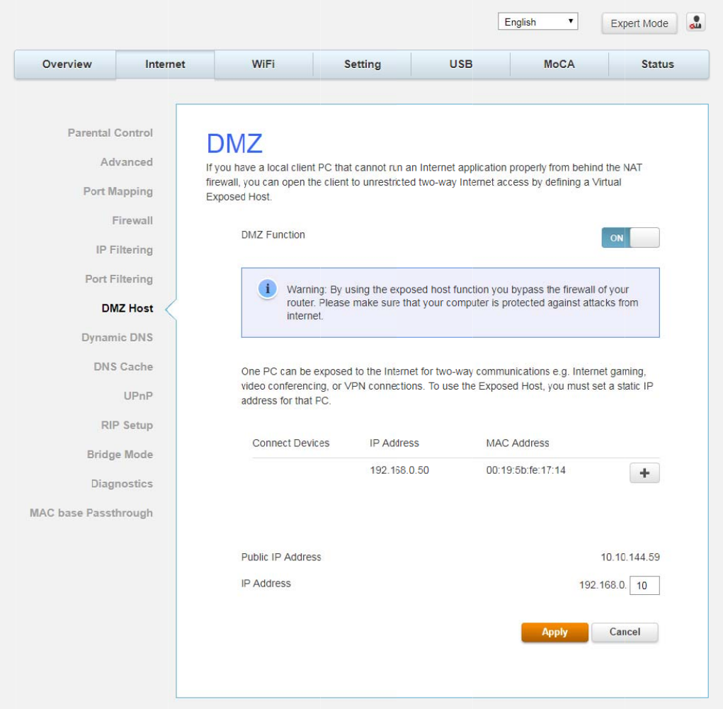
MZ Hos
t
Use this p
the WAN
s
able to ac
c
t
a
g
e to de
s
s
ide, for al
c
ess that
H
s
i
g
nate on
e
l ports. e.
g
H
TTP serv
e
e
PC on y
o
g
., if you
p
e
r by usin
g
Fig.2-32
o
ur LAN th
a
p
ut an HT
T
g
your
g
at
e
Internet\
D
a
t should
b
T
P server o
e
way IP a
d
D
MZ Host
b
e left acc
e
n this ma
c
d
dress as t
h
e
ssible to
a
c
hine, any
o
h
e destina
Page50
/
a
ll PCs fro
m
o
ne will be
tion.
/
71
m
Page51/71
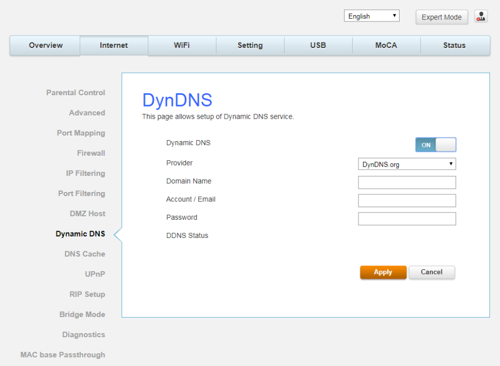
Dynamic DNS
This page allows to setup for Dynamic DNS server.
Fig.2-33 Internet\Dynamic DNS
z Dynamic DNS- Turn “ON” to enable the dynamic DNS function.
z Provider- Choose Provider to enable the basic setting.
z Domain Name- The domain name that you registered with your DDNS provider.
z Account / Email- The account that is registered with your DDNS provider.
z Password- The password that you registered with your DDNS provider
Click Apply to save the changes.
Page52/71
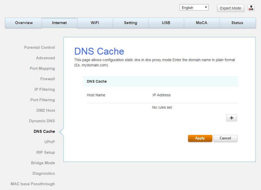
DNS Cache
This page allows configuration static DNS in DNS proxy mode. Enter the domain name in
plain format (Ex. mydomain.com)
Fig.2-34 Internet\DNS Cache
U
U
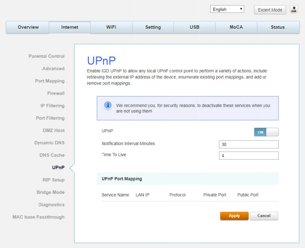
PnP
Enable IG
D
retrievin
g
or remov
e
D
UPnP to
the exter
n
e
port map
allow any
n
al IP addr
e
pin
g
s.
local UPn
P
e
ss of the
Fig.2-
3
P
control
p
device, e
n
3
5 Interne
p
oint to pe
r
n
umerate
e
t\UPnP
r
form a va
e
xistin
g
po
r
riety of ac
t
r
t mappin
g
Page53
/
t
ions, incl
u
g
s, and ad
d
/
71
u
de
d
R
I
I
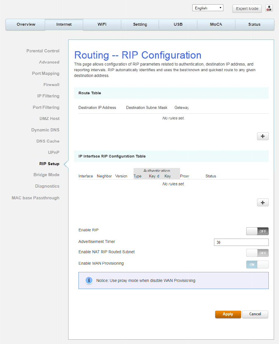
P Setup
T
his pa
g
e
address,
a
known an
d
delays.
allows co
n
a
nd reporti
d
quickest
n
fi
g
uration
n
g
interva
route to
g
of RIP pa
ls. RIP is
u
g
iven desti
n
Fig.2-3
6
rameters
r
u
sed in W
A
n
ation add
6
Internet
\
r
elated to
a
A
N networ
k
resses to
h
\
RIP Setu
p
a
uthentica
t
k
s to ident
i
h
elp reduc
e
p
t
ion, desti
n
i
fy and us
e
e
con
g
esti
o
Page54
/
n
ation IP
e
the best
o
n and
/
71
Page55/71
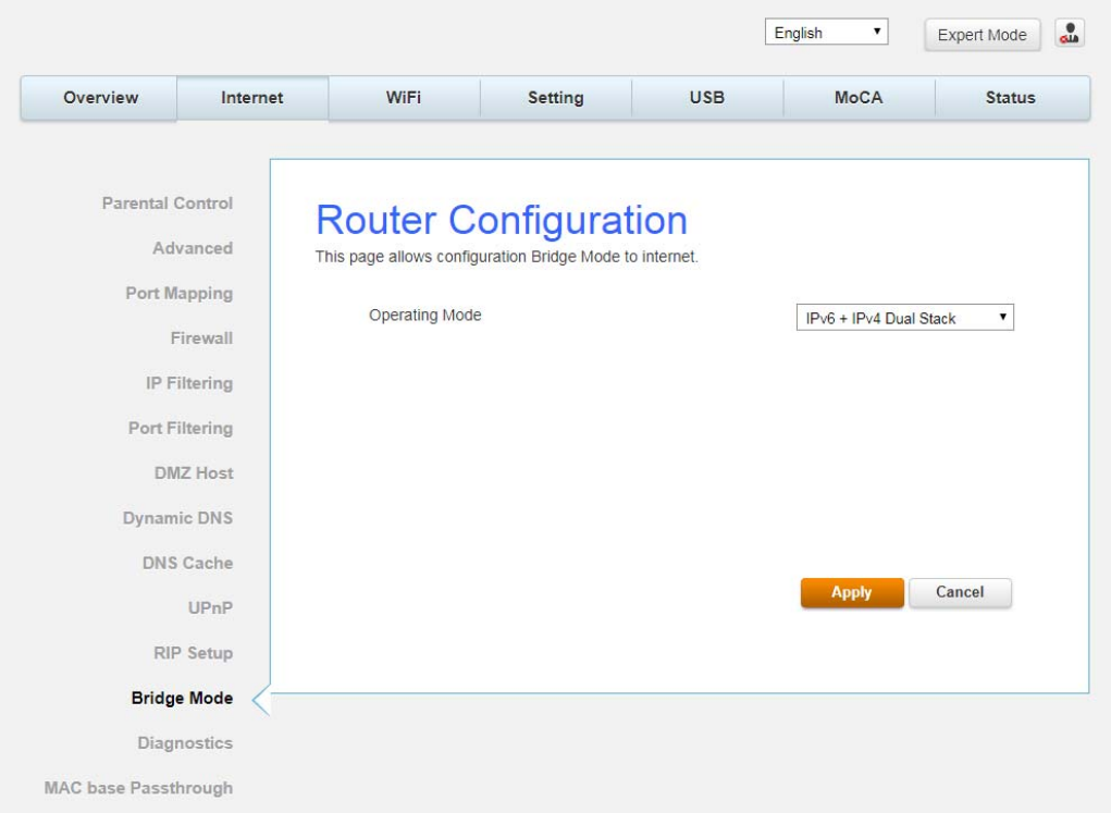
Bridge Mode
This page displays configuration Bridge Mode to internet.
Fig.2-37 Internet\Bridge Mode
D
D
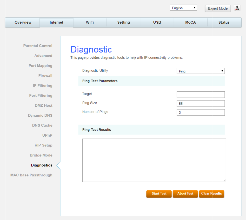
ia
g
nosti
c
T
his pa
g
e
When you
back to y
o
Result will
Results to
Note: Fire
w
behind th
e
most usef
u
your LAN
s
c
offers ba
s
pin
g
an I
n
o
urs. To u
s
be displa
y
clear the
r
w
alls may
e
m. Keep
t
u
l to verif
y
s
ide.
s
ic dia
g
nos
n
ternet de
v
s
e the pin
g
y
ed in the
r
esult con
t
cause pin
g
t
his in min
d
y
connecti
v
tic tools f
o
v
ice, you
s
g
Test, ent
e
lower par
t
t
ents.
g
s to fail b
d
when pi
n
v
ity with P
C
Fig.2-38
o
r you to u
s
end a pa
c
e
r the info
t
of the wi
n
ut still pro
v
ng
a devic
e
C
s which
d
Internet\
D
se when c
o
c
ket to its
T
rmation n
e
n
dow. Pre
s
v
ide you
T
e
that ma
y
d
o not hav
e
D
ia
g
nostic
o
nnectivit
y
T
CP/IP sta
c
e
eded and
s
s Abort T
e
T
CP/IP acc
e
y
be behin
d
e
firewalls,
y
problem
s
c
k, and it
s
press Sta
r
e
st to stop
,
e
ss to sele
d
a firewal
l
such as t
h
Page56
/
s
occur.
s
ends one
r
t Test; th
e
,
and Clea
r
cted devic
l
. Pin
g
is
h
e PCs on
/
71
e
r
es
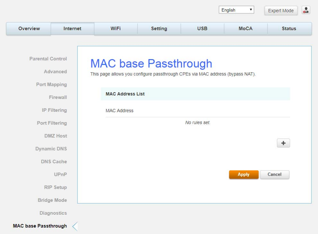
Page57/71
MAC base Passthrough
This page allows you configure passthrough CPEs via MAC address. (bypass NAT)
Fig.2-39 Internet\MAC base Passthrough
Page58/71
Wi-Fi Web Page Group
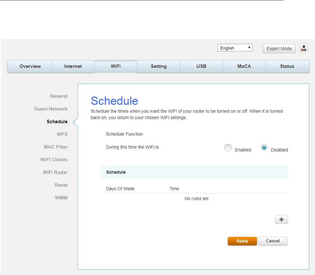
Schedule
Schedule the times when you want the Wi-Fi of your router to be turned on or off. When it is
turned back on, you return to your chosen Wi-Fi settings.
Fig.2-40 Wi-Fi\Schedule
M
M
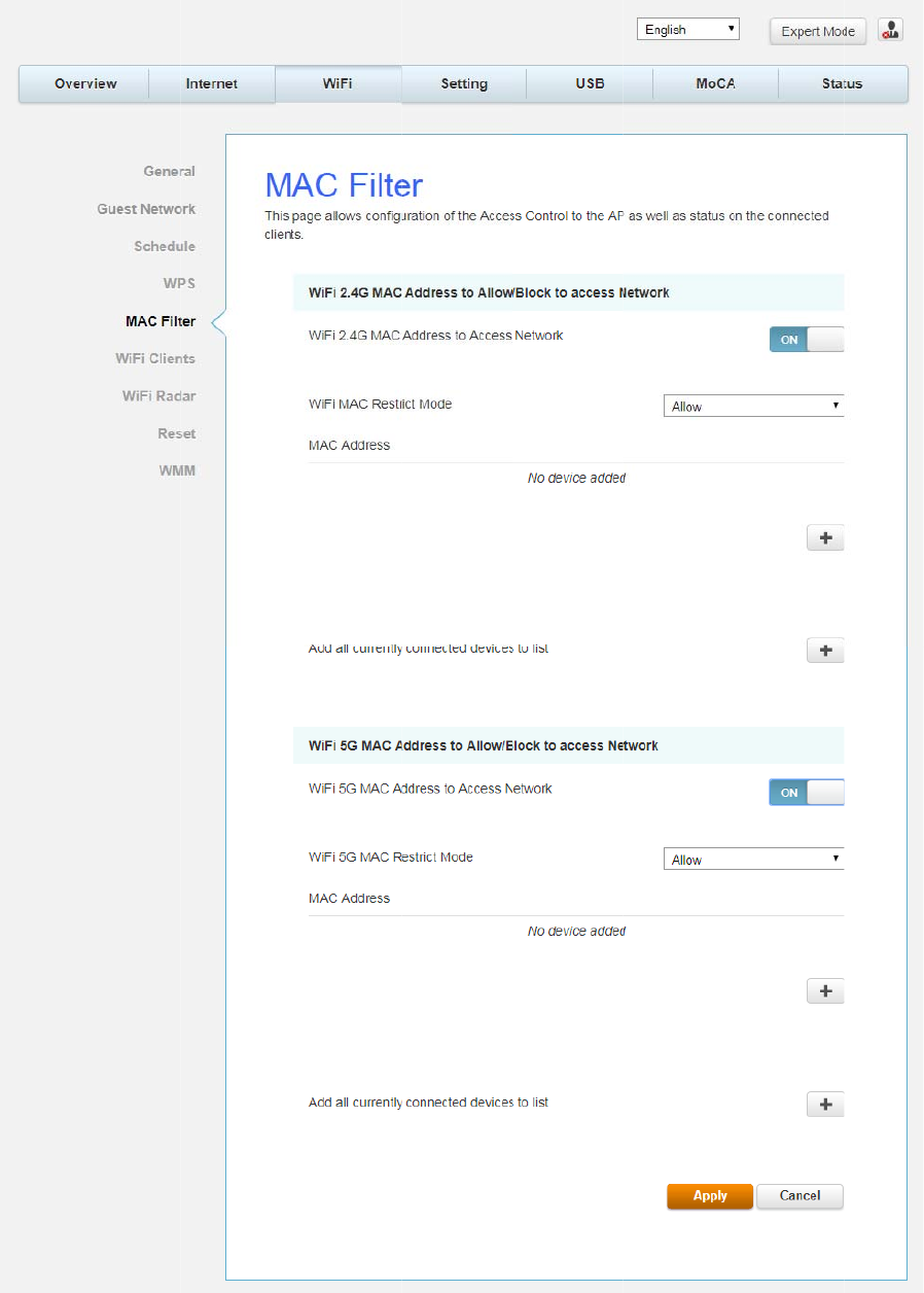
AC Filte
r
By enteri
n
Besides t
h
r
ng
MAC Ad
d
h
e list of M
A
d
ress, you
A
C filter,
a
can confi
g
a
ny local P
C
Fig.2-4
g
ure whic
h
C
s else w
o
1 Wi-Fi\M
A
h
local PCs
o
uld be blo
c
A
C Filter
are allow
e
c
ked to th
e
e
d access
t
e
WAN.
Page59
/
t
o the WA
N
/
71
N
.
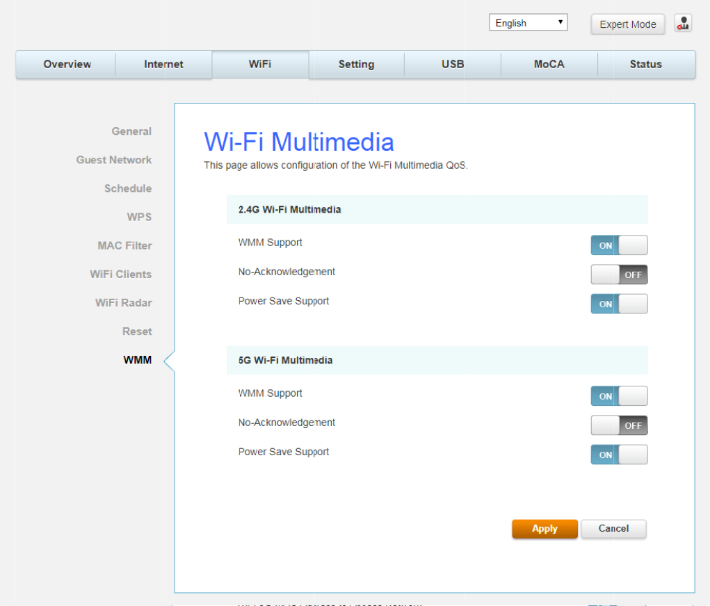
W
W
MM (W
i
T
his pa
g
e
Quality of
z WM
M
z No-
A
z Pow
e
that
a
that i
t
i
-Fi Multi
-
allows yo
u
Service (
Q
M
Suport-
A
cknowle
d
e
r Save S
u
a
re in pow
e
t
has left
p
-
Media)
u
to confi
g
Q
oS) whic
h
If enable
d
dg
ement
-
u
pport-
W
e
r-save m
o
p
ower-sav
e
ure Wi-Fi
M
h
is define
d
Fig.
2
d
, the WM
M
-
When en
a
W
hen Pow
e
o
de. Queu
e
e
mode.
M
ulti-Medi
a
d
by the I
E
2
-42 Wi-Fi\
W
M
informa
t
a
bled, ack
n
e
r Save is
e
e
d packet
s
a
(WMM).
E
EE standa
W
MM
t
ion Eleme
n
owled
g
m
e
e
nabled, t
h
s
are trans
m
WMM is a
n
rd 802.11
e
nt is inclu
d
e
nt for da
t
h
e AP que
u
m
itted wh
e
n
implem
e
e
.
d
ed in bea
c
t
a are not
u
es packe
t
e
n the ST
A
Page60
/
e
ntation of
c
on frame
.
t
ransmitte
t
s for STA
s
A
notifies
A
/
71
.
d.
s
A
P
Page61/71
Settings Web Page Group
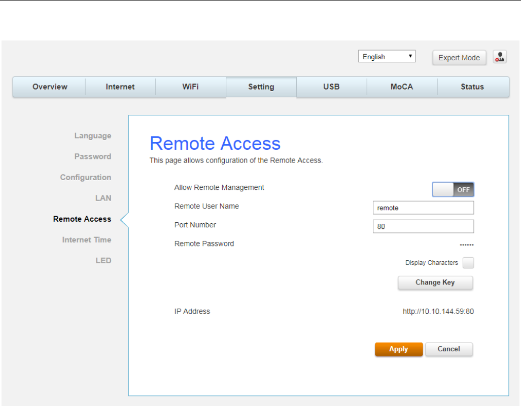
Remote Access
This page allows configuration of the Remote Access.
Fig. 2-43 Setting\Remote Access
z Allow Remote Management: It may help you to Enable or Disable the remote
access function.
z Remote User Name: The user name that when you remote access able to login.
z Port Number: Configure specific port number when you remote access to GUI.
z Remote Password: The remote password that when you remote access able to login.
z IP Address: The IP address that you can use to remote access.
Page62/71
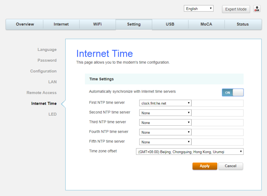
Internet Time
This page display configuration of time servers and the system time obtained from network
servers via Simple Network Time Protocol. The system has to be reset for any changes to
take effect.
Fig.2-44 Setting\Internet Time
Page63/71
USB Web Page Group
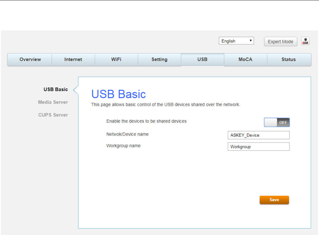
USB Basic
This page allows basic control of the USB devices shared over the network.
Fig.2-45 USB\USB Basic
Page64/71
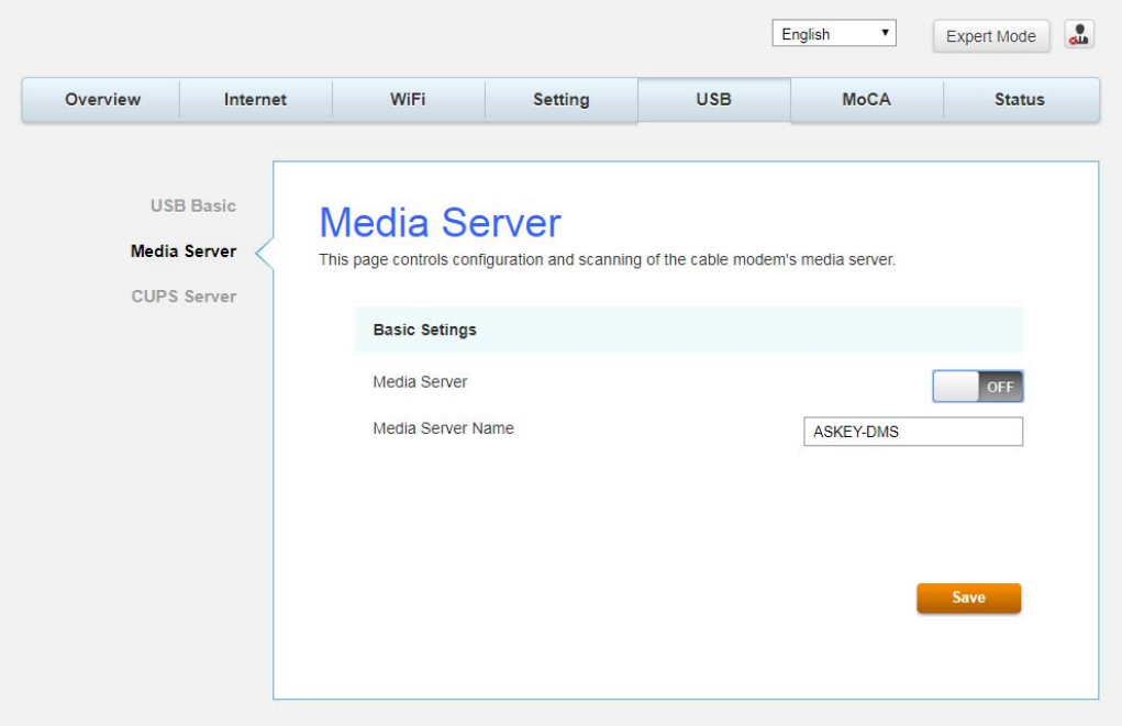
Media Server
This page controls configuration and scanning of the cable modem’s media server.
Fig.2-46 USB\Media Server
Page65/71
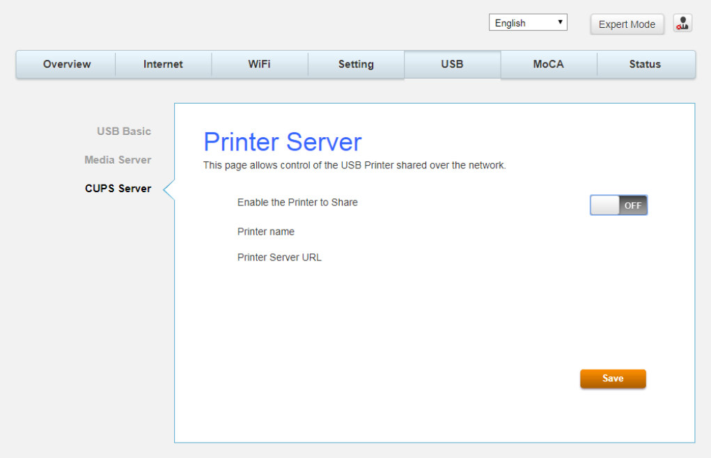
CPUS Server
This page allows control of the USB Printer shared over the network.
Fig.2-47 USB\CPUS Server

Page66/71
CHAPTER 3: ADDITIONAL INFORMATION
Frequently Asked Questions
Q. How do I get the system installed?
A. Professional installation from your cable provider is strongly recommended. They will ensure
proper cable connection to the modem and your computer. However, your retailer may have
offered a self- installation kit, including the necessary software to communicate with your
cable ISP.
Q. Once my Cable Modem is connected, how do I get access to the Internet?
A. Your local cable company provides your internet service*, offering a wide range of services
including email, chat, and news and information services, and a connection to the World
Wide Web.
Q. Can I watch TV, surf the Internet, and talk to my friends through the Cable
Modem at the same
time?
A. Absolutely!
Q. What do you mean by “Broadband?”
A. Simply put, it means you’ll be getting information through a “bigger pipe,” with more
bandwidth, than a standard phone line can offer. A wider, “broader” band means more
information, more quickly.
Q. What is DOCSIS and what does it mean?
A. “Data over Cable Service Interface Specifications” is the industry standard that most cable
companies are adopting as they upgrade their systems. Should you ever decide to move, the
Cable Modem will work with all upgraded cable systems that are DOCSIS-compliant.
* Monthly subscription fee applies.
** Additional equipment required. Contact your Cable Company and ISP for any restrictions or
additional fees.

Page67/71
General Troubleshooting
You can correct most problems you have with your product by consulting the troubleshooting
list that follows.
I can’t access the internet.
z Check all of the connections to your Cable Modem.
z Your Ethernet card may not be working. Check each product’s documentation for more
information.
z The Network Properties of your operating system may not be installed correctly or the
settings may be incorrect. Check with your ISP or cable company.
I can’t get the modem to establish an Ethernet connection.
z Even new computers don’t always have Ethernet capabilities – be sure to verify that your
computer has a properly installed Ethernet card and the driver software to support it.
z Check to see that you are using the right type of Ethernet cable.
The modem won’t register a cable connection.
z If the modem is in Initialization Mode, the INTERNET light will be flashing. Call your Cable
Company if it has not completed this 5-step process within 30 minutes, and note which
step it is getting stuck on.
z The modem should work with a standard RG-6 coaxial cable, but if you’re using a cable
other than the one your Cable Company recommends, or if the terminal connections are
loose, it may not work. Check with your Cable Company to determine whether you’re using
the correct cable.
z If you subscribe to video service over cable, the cable signal may not be reaching the
modem. Confirm that good quality cable television pictures are available to the coaxial
connector you are using by connecting a television to it. If your cable outlet is “dead”, call
your Cable Company.
z Verify that the Cable Modem service is DOCSIS compliant by calling your cable provider.

Page68/71
Service Information
If you purchased or leased your Cable Modem directly from your cable company, then warranty
service for the Digital Cable Modem may be provided through your cable provider or its
authorized representative. For information on 1) Ordering Service, 2) Obtaining Customer
Support, or 3) Additional Service Information, please contact your cable company. If you
purchased your Cable Modem from a retailer, see the enclosed warranty card.

Page69/71
Federal Communication Commission Interference Statement
This device complies with Part 15 of the FCC Rules. Operation is subject to the following two
conditions: (1) This device may not cause harmful interference, and (2) this device must accept
any interference received, including interference that may cause undesired operation.
This equipment has been tested and found to comply with the limits for a Class B digital device,
pursuant to Part 15 of the FCC Rules. These limits are designed to provide reasonable
protection against harmful interference in a residential installation. This equipment generates,
uses and can radiate radio frequency energy and, if not installed and used in accordance with
the instructions, may cause harmful interference to radio communications. However, there is
no guarantee that interference will not occur in a particular installation. If this equipment does
cause harmful interference to radio or television reception, which can be determined by turning
the equipment off and on, the user is encouraged to try to correct the interference by one of
the following measures:
- Reorient or relocate the receiving antenna.
- Increase the separation between the equipment and receiver.
- Connect the equipment into an outlet on a circuit different from that
to which the receiver is connected.
- Consult the dealer or an experienced radio/TV technician for help.
FCC Caution: Any changes or modifications not expressly approved by the party responsible for
compliance could void the user's authority to operate this equipment.
This transmitter must not be co-located or operating in conjunction with any other antenna or
transmitter.
For operation within 5.15 ~ 5.25GHz frequency range, it is restricted to indoor environment.
This device meets all the other requirements specified in Part 15E, Section 15.407 of the FCC
Rules.
Page70/71
FOR MOBILE DEVICE USAGE (>32cm/low power)
Radiation Exposure Statement:
This equipment complies with FCC radiation exposure limits set forth for an uncontrolled
environment. This equipment should be installed and operated with minimum distance 32cm
between the radiator & your body.
FOR COUNTRY CODE SELECTION USAGE (WLAN DEVICES)
Note: The country code selection is for non-US model only and is not available to all US model.
Per FCC regulation, all Wi-Fi products marketed in US must fix to US operation channels only.

Page71/71
CAUTION for UL (Check caution label on gift box)
North American Cable Installer:
This reminder is provided to call your attention to Article 820.93 of the National Electrical Code
(Section 54 of the Canadian Electrical Code, Part 1) which provides guidelines for proper
grounding and, in particular, specifies that the cable ground shall be connected to the
grounding system of the building as close to the point of cable entry as practical.