Askey Computer TCG310 Access Point User Manual UM PKE2048JM U84 RoHS TCG310 V1 0 20170502 1
Askey Computer Corp Access Point UM PKE2048JM U84 RoHS TCG310 V1 0 20170502 1
Contents
User Manual
Page 1 / 65
TCG310
USER MANUAL
Page 2 / 65
SAFETY INSTRUCTIONS AND REGULATORY NOTICES ................................................................. 5
Chapter 1: Connections and Setup ....................................................................................................... 10
Cable Modem Overview .......................................................................................................................................... 10
Front Panel ...................................................................................................................... 10
Rear Panel ....................................................................................................................... 12
Bottom Side Panel for TEL ................................................................................................. 13
Wall Mounting .................................................................................................................. 14
Relationship among the Devices ........................................................................................................................... 15
What the Modem Does ...................................................................................................... 15
What the Modem Needs to Do Its Job ................................................................................. 15
Contact Your Local Cable Company ..................................................................................... 16
Connecting the Wireless Voice Gateway to a Single Computer ..................................................................... 16
Attaching the Cable TV Wire to the Wireless Voice Gateway ................................................... 17
Installation procedure for connecting to the Ethernet interface ............................................... 18
Telephone or Fax Connection ............................................................................................. 19
Chapter 2: WEB Configuration ............................................................................................................... 20
Accessing the Web Configuration ......................................................................................................................... 20
Overview Web Page Group .................................................................................................................................... 22
Overview ......................................................................................................................... 22
Internet Web Page Group ...................................................................................................................................... 23
Advanced ........................................................................................................................ 23
Port Mapping.................................................................................................................... 24
Parental Control ................................................................................................................ 25
Firewall ........................................................................................................................... 26
IP Filtering ....................................................................................................................... 27
DMZ Host ........................................................................................................................ 28
Dynamic DNS ................................................................................................................... 29
DNS Cache....................................................................................................................... 30
UPnP ............................................................................................................................... 31
RIP Setup ........................................................................................................................ 32
Diagnostic ........................................................................................................................ 33
MAC base Passthrough ...................................................................................................... 34
Page 3 / 65
Wi-Fi Web Page Group ............................................................................................................................................ 35
General ........................................................................................................................... 35
WPS ................................................................................................................................ 39
MAC Filter ........................................................................................................................ 40
Reset .............................................................................................................................. 41
Settings Web Page Group ...................................................................................................................................... 42
Language ........................................................................................................................ 42
Password ......................................................................................................................... 43
Configuration ................................................................................................................... 44
LAN ................................................................................................................................ 45
Internet Time ................................................................................................................... 46
LED ................................................................................................................................ 47
USB Web Page Group .............................................................................................................................................. 48
USB Basic ........................................................................................................................ 48
Media Server .................................................................................................................... 49
CPUS Server ..................................................................................................................... 50
MoCA Web Page Group ........................................................................................................................................... 51
MoCA .............................................................................................................................. 51
Status Web Page Group .......................................................................................................................................... 52
Status ............................................................................................................................. 52
Voice Status ..................................................................................................................... 53
Upstream ......................................................................................................................... 54
Downstream .................................................................................................................... 55
Event log ......................................................................................................................... 56
Spectrum Analyzer ............................................................................................................ 57
Chapter 3: Additional Information ........................................................................................................ 58
Frequently Asked Questions .................................................................................................................................. 58
General Troubleshooting ......................................................................................................................................... 59
Service Information ................................................................................................................................................. 60
Federal Communication Commission Interference Statement ....................................................................... 61
Industry Canada statement: .................................................................................................................................. 63
CAUTION for UL (Check caution label on gift box) .......................................................................................... 65
Page 4 / 65
Page 5 / 65
SAFETY INSTRUCTIONS AND REGULATORY NOTICES
Product Safety Notice
Before installing or using the product, read these instructions carefully. Be sure to comply
strictly precautions.
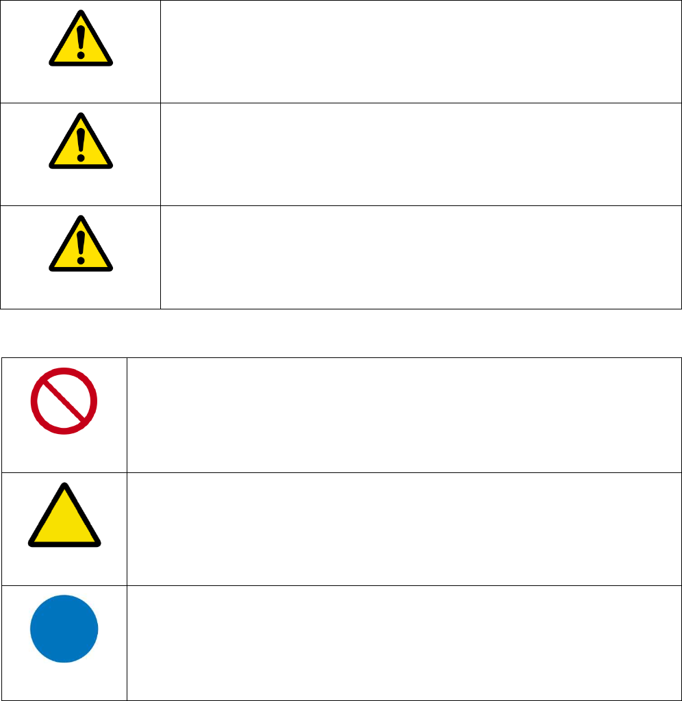
Explanation of risk levels
DANGER
This indication is given where there is an immediate danger of death
or serious injury if the person in charge or any third party mishandles
the machine or does not avoid the dangerous situation when
operating or maintaining the machine.
WARNING
This indication is given where there is a potentiality for death or
serious injury if the person in charge or any third party mishandles
the machine or does not avoid the dangerous situation when
operating or maintaining the machine.
CAUTION
This indication is given where there is a danger of medium to minor
injury if the person in charge or any third party mishandles the
machine or does not avoid the dangerous situation when operating
or maintaining the machine.
Explanation of pictorial warning indi
cations and warning labels
Prohibited
It is used to prohibit its conduct in handling products.
Specific prohibited contents are indicated by pictures and sentences in or
near the figure symbol.
Caution
It is used to call attention to ignition, electric shock, high temperature,
etc. in the handling of products.
Specific notes content is indicated by a picture or sentence in or near the
figure symbol.
Instruction
Used to force actions based on instructions in the handling of products.
Specific instruction content is indicated by a picture or sentence in or near
the figure symbol.
Page 6 / 65
LIMITATIONS OF LIABILITY
This equipment has been designed for domestic use inside a building. In some
environments or circumstances, the use of wireless devices may be prohibited by
the owner of the building or responsible representatives of the organization. If in
doubt about the policy applying to the use of wireless devices in an organization
where a specific environment (e.g. airports), you should ask for permission to use
the device before turn it on. ASKEY assumes no liability for non-compliance with
regulations on the installation site, and radio interference created vis-à-vis third
parties and due to non-compliance with national regulations for this application.
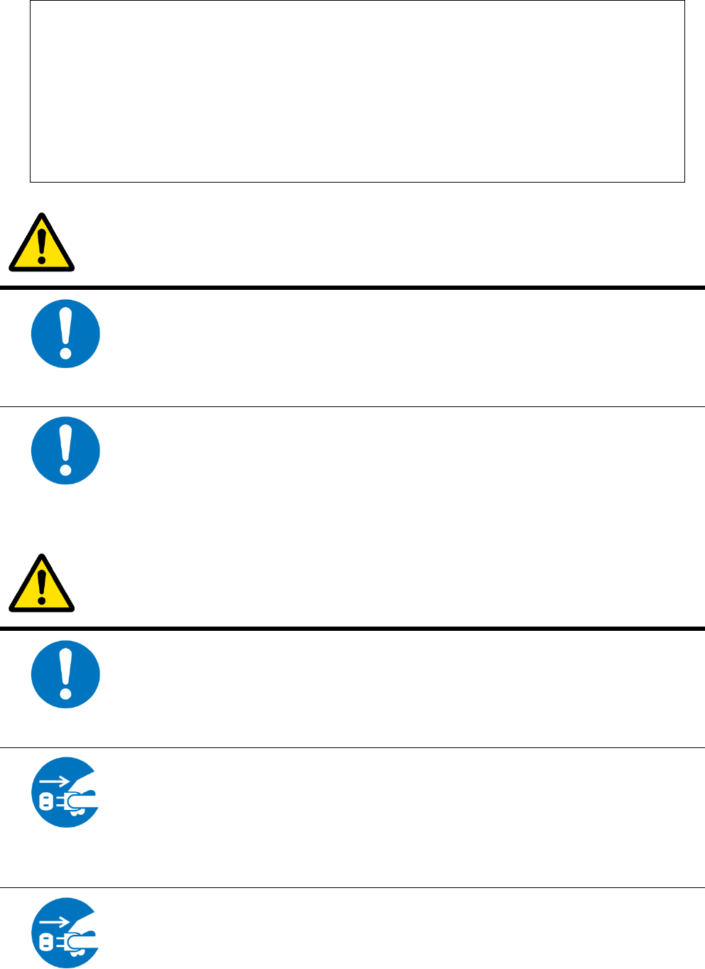
DANGER
Instruction
Do not overload wall outlet or extension cords as this may increase the
risk of electric shock or fire. If the power cord is frayed, replace it with a
new one.
Instruction
Do not attempt to connect with any computer accessory or electronic
product without instructions from qualified service personnel. This may
result in risk of electronic shock or fire.
WARNING
Instruction
Proper ventilation is necessary to prevent the product overheating. Do not
block or cover the slots and openings on the product, which are intended
for ventilation and proper operation.
Unplug the
power plug
When the product is expected to be not in use for a period of time,
unplug the power cord of the product to prevent it from the damage of
storm or sudden increases in rating.
Unplug the
Accidental penetrations of small metal objects (such as pins, paper clips,
etc.) disconnect the equipment from the mains as soon as possible (risk
of electric shock) and contact your Customer Service to find out how to
proceed. Do not reconnect the product as a foreign object has not been
eliminated. Unplug the product immediately if you notice it exudes a smell
Page 7 / 65
power plug
of burning or smoke. You should never open the unit yourself because
you could be electrocuted.
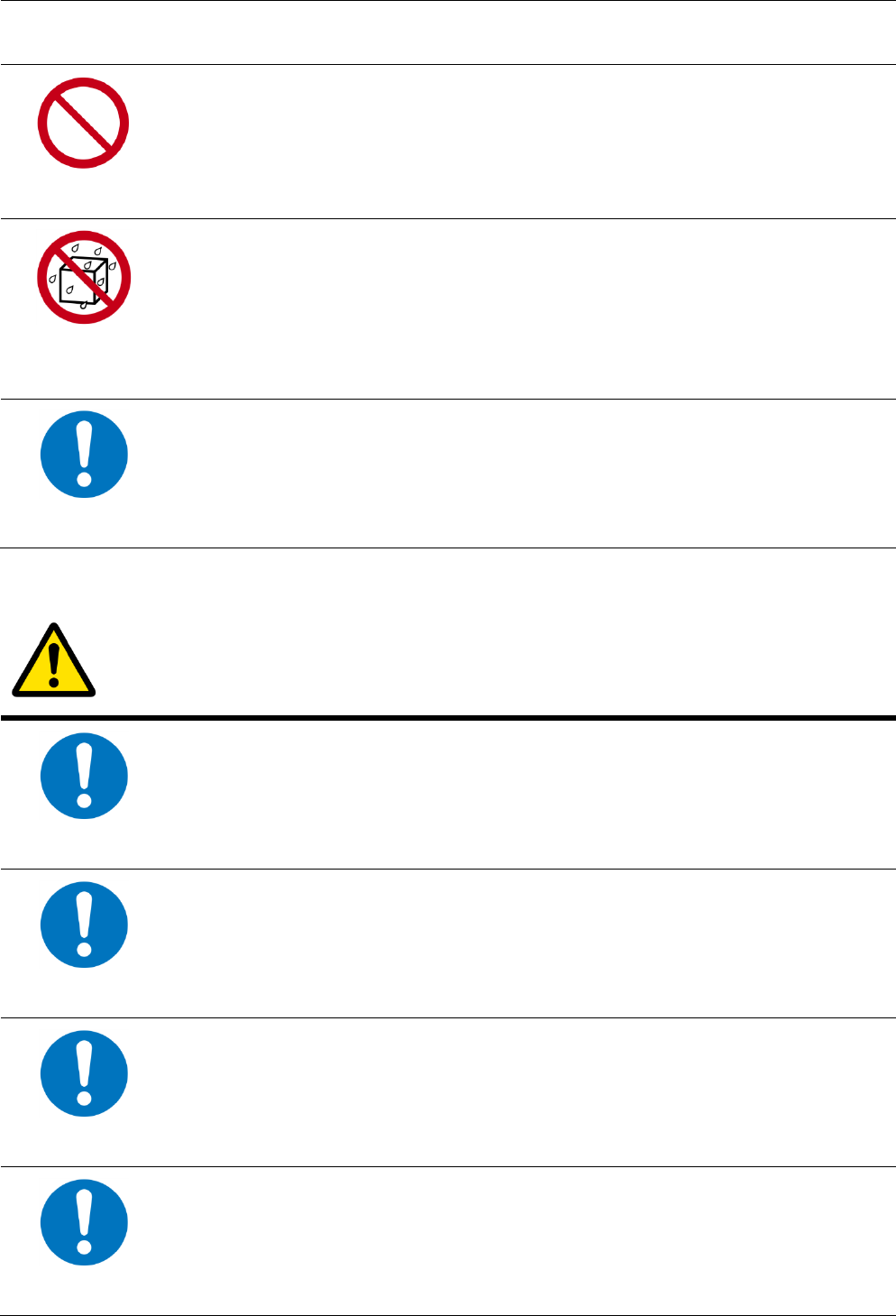
Prohibited
Do not place the product near any source of heat or expose it to direct
sunlight.
Water wet
prohibition
Do not expose the product to moisture. Never spill any liquid on the
product.
Instruction
Avoid connecting or using this product during a lightning storm.
Disturbances transmitted through the grid and / or telephone can cause
electric shock in the product and people.
CAUTION
Instruction
Use only power adapter supplied with the product. This appliance is
designed to operate in the rated voltage 90~100 VAC.
Instruction
Do not place this product on unstable stand or table.
Instruction
This product is designed for stationary use in an office or a room in the
home for a maximum ambient temperature of 40 ° C (104 ° F).
Instruction
To allow the disconnection of the device in case of problems, make sure
the base of the outlet you plug the power cord is easily accessible and is
located as close as possible to the equipment.
Page 8 / 65
Instruction
Leave 7cm to 10cm around the appliance to ensure that proper
ventilation gets to it.
Be sure to
connect the
ground wire
The screen of the coaxial cable is intended to be connected to earth in
the building installation.
Disassembly
prohibited
Do not attempt to disassemble or open covers of this unit by yourself. Nor
should you attempt to service the product by yourself, which may void
the user’s authority to operate it. Contact qualified service personnel
under the following conditions:
1. If the power cord or plug is damaged or frayed.
2. If liquid has been spilled into the product.
3. If the product has been exposed to rain or water.
4. If the product does not operate normally when the operating
instructions are followed.
5. If the product has been dropped or the cabinet has been
damaged.
6. If the product exhibits a distinct change in performance.
7. If a cable is damaged or frayed provided.
8. If the unit is dropped or damaged in any way.
9. If there is a noticeable signs of overheating
Unplug the
power plug
Power off and unplug this product from the wall outlet when it is not in
use or before cleaning. Pay attention to the temperature of the power
adapter. The temperature might be high.
Instruction
Do not store the Cable Modem product in excessively hot, cold or damp
conditions. Operation Environmental:
‧ Operation Temperature: 5°C ~ 40°C
‧ Storage Temperature: -20°C ~ +70°C
To clean the appliance, use a dry, clean soft cloth with no cleaning
solvent or abrasive products. Clean the ventilation openings regularly.

Page 9 / 65
Instruction
Instruction
Under normal use condition the user shall keep at least 20cm from the
Cable Modem product.
Page 10 / 65
CHAPTER 1: CONNECTIONS AND SETUP
Cable Modem Overview
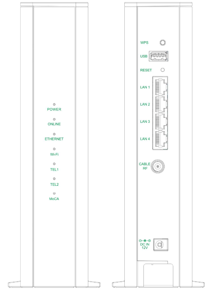
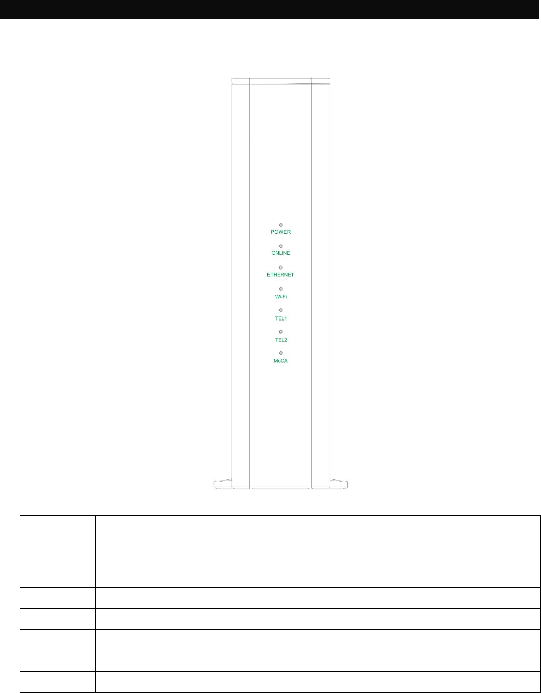
Front Panel
Fig. 1-1 Front Panel
POWER
Indicates the
power
status.
ONLINE
Displays the status of your cable connection.
The light is off when no cable
connection is detected and fully lit when the modem has established a
connection with the network and data can be transferred.
ETHERNET
In
dicates the state of Ethernet ports
.
Wi
-
Fi
Indicates the traffic on the wireless network
.
TEL
1 / 2 Indicates the status of the telephone ports.
MoCA
Indicates the status of the
MoCA
functionality
.

Page 11 / 65
LED from top to bottom.
LED
Status
Description
POWER
ON
OFF
The device is on.
The device boot fail or no power.
ONLINE
ON
OFF
FLASH
The device is ready for use. Now you can link to
the internet.
The device is not link to the internet yet or not registration.
The device is in registration process.
ETHERNET
ON
OFF
FLASH
LAN port is connected to the PC.
LAN port is not connected to the PC.
Traffic on the LAN is working.
Wi-Fi
ON
OFF
FLASH
Wi
-
Fi is enabled.
Wi-Fi is disabled.
Wi-Fi traffic is working.
TEL 1 / 2
ON
OFF
FLASH
Phone is ready registration for use.
Phone is not able to use.
Phone interface is in registration process.
MoCA
ON
OFF
FLASH
MoCA
is enabled.
MoCA is disabled.
MoCA traffic is working.
Table 1-1 LED behavior
Page 12 / 65
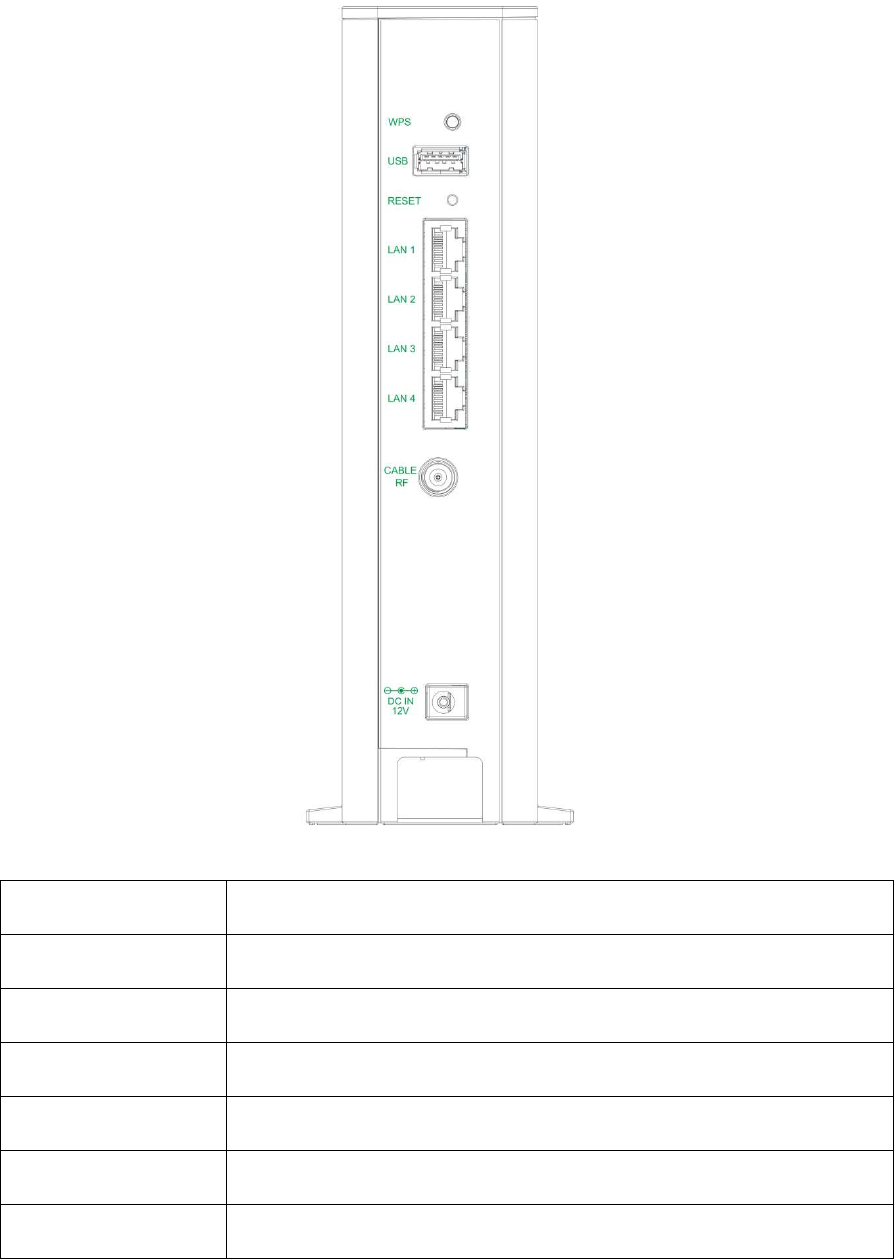
Rear Panel
Fig. 1-2 Rear Panel
Slot
Description
WPS Enables scanning for available WPS client device
USB
USB 3.0 host connector (software upgrade only)
RESET
Reset/Reboot this Cable modem
LAN 1 / 2 / 3 / 4
Ethernet 10/100/1000 Base-T RJ-45 connector
CABLE RF
F-Connector
12VDC
12V DC-IN Power connector.
Table 1-2 Rear Panel description
Page 13 / 65
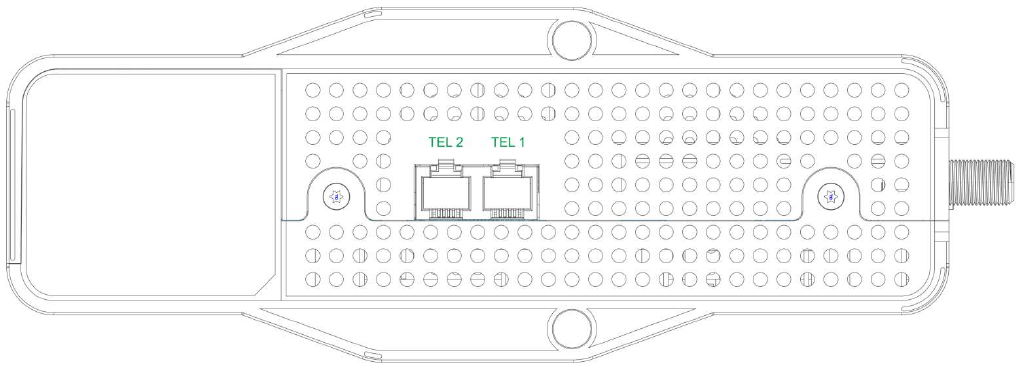
Bottom Side Panel for TEL
Fig. 1-3 Bottom Side Panel
The TEL 1 / 2 on the Bottom Side panel of TCG310, you can use telephony RJ-11
Connector.
Page 14 / 65
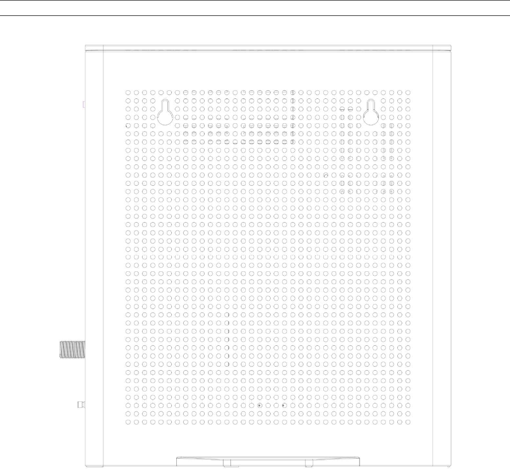
Wall Mounting
The number of the screw 2 pcs.
Direction for wall mounting: Tuner downward or leftward or rightward.
Dimension for the screw: diameter: 3.5 mm; length: 30 mm.
There are 2 slots on the side of the CABLE MODEM that can be used for wall mounting.
Note: When wall mounting the unit. Ensure that it is within reach of the power outlet.
Fig. 1-4 Wall Mounting
To do this:
1. For the cable modem, ensure that the wall you use is smooth, flat, dry and sturdy
and use the 2 screws holes.
2. The unit can be to use solid concrete wall and/or hard wood wall.
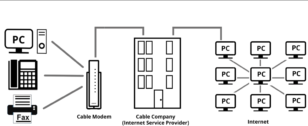
Relationship among the Devices
This illustration shows a cable company that offers
PacketCable/Euro-PacketCable
compliant voice/data
What the Modem Does
The Wireless Voice Gateway provides high
quality telephone voice and fax/modem services over residential, commercial, and education
subscribers on public and private networks via an existing CATV infras
operate with the PacketCable
compliant head
communications. The IP traffic can transfer between the Wireless Voice Gateway and
DOCSIS/Euro-DOCSIS
compliant head
downstream communications.
What the Modem Needs to Do Its Job
The Right Cable Company:
services that use cable
TV industry
PacketCable/Euro-
PacketCable
The Internet/Telephony Service Provider (ISP/TSP):
provides you access to an Internet Service Provider (ISP) and Telephony Service Provider
(TSP). The ISP is your gateway to the Internet
access Internet content on the World Wide Web (WWW). The TSP provides you with
telephony access to other modems or other telephony services over the Public Switched
Telephone Network (PSTN).
Check with your cable compan
y to make sure you have everything you need to begin; they’ll
know if you need to install special software or re
internet service work for you.
Relationship among the Devices
This illustration shows a cable company that offers
DOCSIS/Euro-
DOCSIS
compliant voice/data
services.
Fig. 1-5 Connection overview
The Wireless Voice Gateway provides high
-
speed Internet access as well as cost
quality telephone voice and fax/modem services over residential, commercial, and education
subscribers on public and private networks via an existing CATV infras
tructure. It can inter
compliant head
-
end equipment and provide the IP
communications. The IP traffic can transfer between the Wireless Voice Gateway and
compliant head
-end equipment. The data sec
urity secures upstream and
What the Modem Needs to Do Its Job
The Right Cable Company:
Make sure your local cable company provides data
TV industry
-standard DOCSIS/Euro-
DOCSIS
PacketCable
compliant technology.
The Internet/Telephony Service Provider (ISP/TSP):
Your cable company
provides you access to an Internet Service Provider (ISP) and Telephony Service Provider
(TSP). The ISP is your gateway to the Internet
and provides you with a pipeline to
access Internet content on the World Wide Web (WWW). The TSP provides you with
telephony access to other modems or other telephony services over the Public Switched
Telephone Network (PSTN).
y to make sure you have everything you need to begin; they’ll
know if you need to install special software or re
-
configure your computer to make your cable
Page 15 / 65
DOCSIS
and
speed Internet access as well as cost
-effective, toll-
quality telephone voice and fax/modem services over residential, commercial, and education
tructure. It can inter
-
end equipment and provide the IP
-based voice
communications. The IP traffic can transfer between the Wireless Voice Gateway and
urity secures upstream and
Make sure your local cable company provides data
DOCSIS
compliant and
Your cable company
provides you access to an Internet Service Provider (ISP) and Telephony Service Provider
and provides you with a pipeline to
access Internet content on the World Wide Web (WWW). The TSP provides you with
telephony access to other modems or other telephony services over the Public Switched
y to make sure you have everything you need to begin; they’ll
configure your computer to make your cable

Page 16 / 65
Contact Your Local Cable Company
You will need to contact your cable company to establish an Internet account before you can
use your gateway. You should have the following information ready (which you will find on the
sticker on the gateway):
• The serial number
• The model number
• The Cable Modem (CM) Media Access Control (MAC) address
• The Terminal Adapter (EMTA) MAC address
• Security information: Service Set Identifier (SSID), Encryption key / passphrase
(WPA2-PSK by default), channel number. Default values are indicated underneath the
modem on the sticker.
Please check the following with the cable company
The cable service to your home supports DOCSIS/Euro-DOCSIS compliant two-way
modem access.
Your internet account has been set up. (The Media Terminal Adapter will provide data
service if the cable account is set up but no telephony service is available.)
You have a cable outlet near your PC and it is ready for Cable Modem service.
Note: It is important to supply power to the modem at all times. Keeping your modem plugged
in will keep it connected to the Internet. This means that it will always be ready whenever you
need.
Important Information
Your cable company should always be consulted before installing a new cable outlet. Do not
attempt any rewiring without contacting your cable company first.
Please verify the following on the Wireless Voice Gateway
The Power LED should be lighted when plug-in the power supply.
Connecting the Wireless Voice Gateway to a Single Computer
This section of the manual explains how to connect your Wireless Voice Gateway to the
Ethernet port on your computer and install the necessary software. Please refer to Figure 1-7
to help you connect your Digital Cable Modem for the best possible connection.
Page 17 / 65
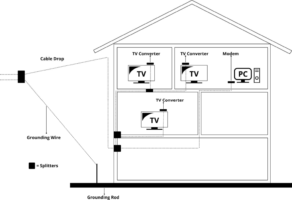
Attaching the Cable TV Wire to the Wireless Voice Gateway
1. Locate the Cable TV wire. You may find it one of three ways:
a. Connected directly to a TV, a Cable TV converter box, or VCR. The line will be
connected to the jack, which should be labeled either IN, CABLE IN, CATV, CATV IN,
etc.
b. Connected to a wall-mounted cable outlet.
c. Coming out from under a baseboard heater or other location. See Figure 1-6 for the
wiring example.
Notes: For optimum performance, be sure to connect your Wireless Voice Gateway to the first point
the cable enters your home. The splitter must be rated for at least 1GHz.
Fig. 1-6 Basic Home Wiring
Page 18 / 65
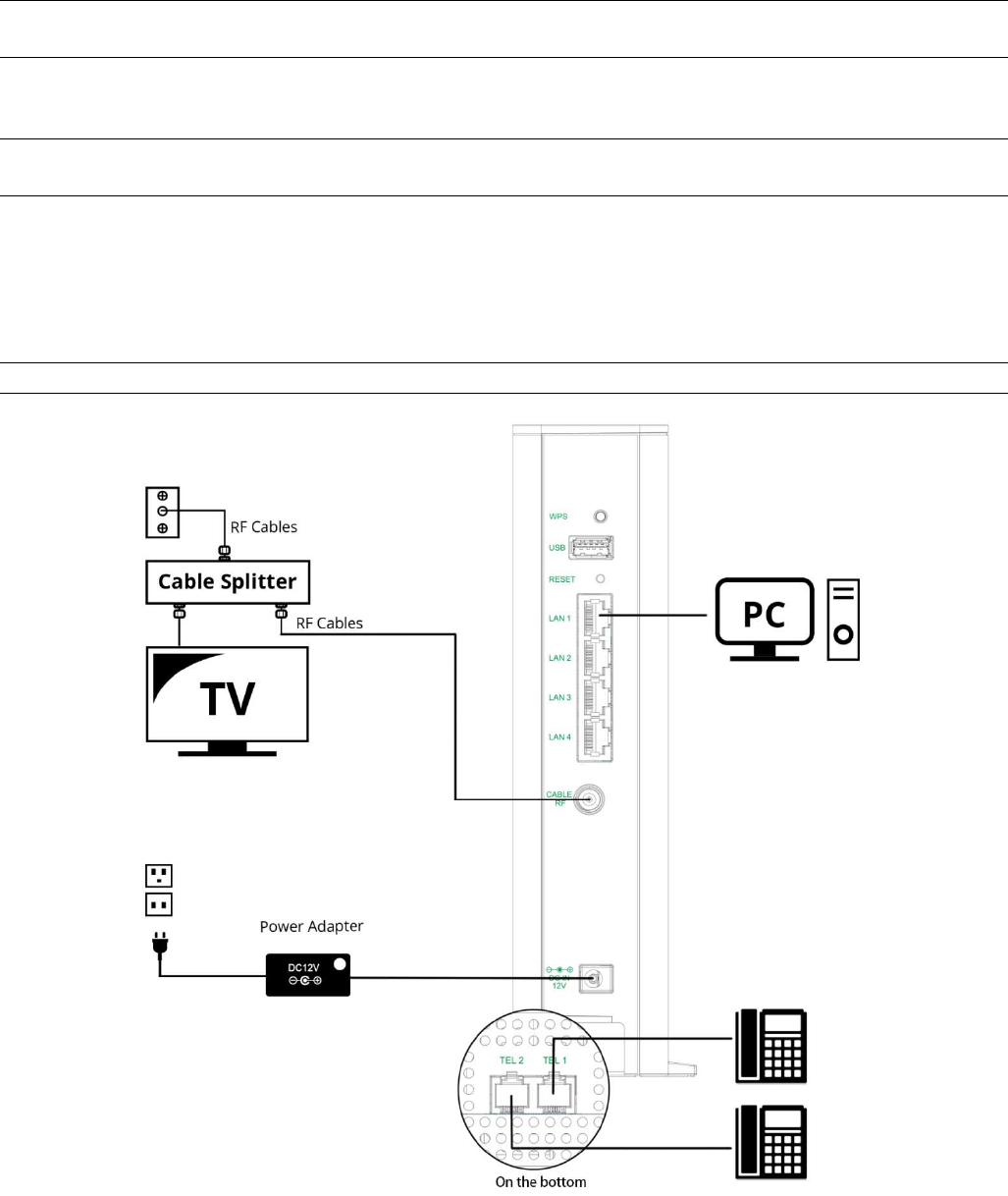
Installation procedure for connecting to the Ethernet interface
Follow these steps for proper installation.
(Please refer to Fig. 1-7)
Plug the coaxial cable to the cable wall outlet and the other end to the modem’s cable
connector.
Note: To ensure a fast registration of the modem, the coaxial cable must be connected to
the modem before it is powered on.
Plug the power adapter into the socket of the cable modem and two-pin plug in the AC outlet to
power on the modem.
Note: Only use the power adapter that comes with the modem. Using another power
adapter can cause damage to the product, and will void the warranty.
Connect an Ethernet cable (direct connection, see below) to the Ethernet port at the back of
the computer, and the other end to the ETHERNET port on the rear panel of the cable modem.
The modem will seek the appropriate cable signal on the cable television network and go
through the initial registration process on its own. The modem is ready for data transfer after
the green LED "ONLINE" is lit continuously.
Note: the button "RESET" at the back of the modem is used primarily for maintenance.
Fig. 1-7 Connect to the Modem
Page 19 / 65
Telephone or Fax Connection
When properly connected, most telephony devices can be used with the Wireless Voice
Gateway
just as with a conventional telephone service. To make a normal telephone call, pick
up the handset; listen for a dial tone, then dial the desired number. For services such as call
waiting, use the hook switch (or FLASH button) to change calls. The following procedures
describe some of the possible connection schemes for using telephony devices with the
Wireless Voice Gateway.
1. Connect a standard phone line cord directly from the phone (fax machine, answering
machine, caller ID box, etc.) to one of the TEL jacks on the
Wireless Voice Gateway.
2. If there is a phone line in your home which is NOT connected to another telephone service
provider, connect a standard phone line cord from a jack on this line to one of the TEL jacks
of the Wireless Voice Gateway. Connect a standard phone line cord directly from the phone
(fax machine, answering machine, caller ID box, etc.) to one of the other jacks in the house
that uses that line.
3. If you have a multi-line telephone, connect a standard phone line cord (not an RJ-14 type
line cord) from the phone to the TEL jacks on the Wireless Voice Gateway. (Other phones
can be added to each line by using standard phone line splitters.)
Page 20 / 65
CHAPTER 2: WEB CONFIGURATION
To make sure that you can access the Internet successfully, please check the following first.
1. Make sure the connection (through Ethernet) between the Wireless Voice Gateway and
your computer is OK.
2. Make sure the TCP/IP protocol is set properly.
3. Subscribe to a Cable Company.
Accessing the Web Configuration
The Wireless Voice Gateway offers local management capability through a built-in HTTP
server and a number of diagnostic and configuration web pages. You can configure the settings
on the web page and apply them to the device.
Once your host PC is properly configured; please proceed as follows:
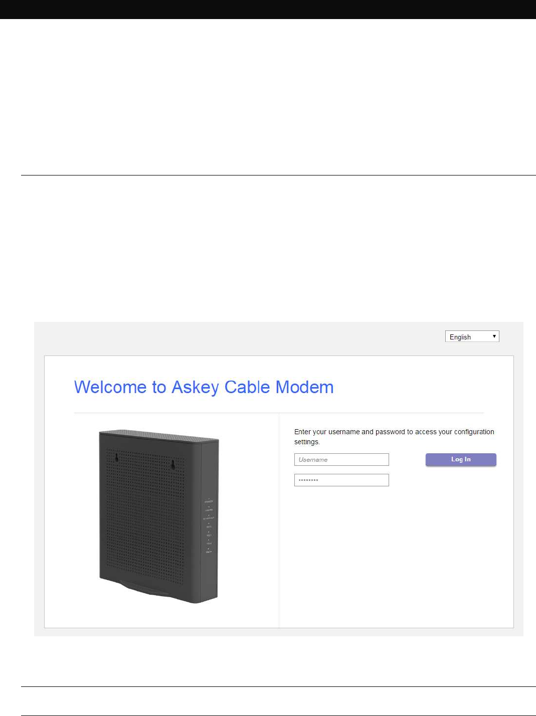
1. Start your web browser and type the private IP address of the Wireless Voice
Gateway on the URL field: 192.168.100.1
2. After connecting to the device, you will be prompted to enter username and
password. By default, the username is "user" and password is "user".
Fig2-1 Login dialogue
Note: If forget your username and password, you may Press "Reset" button on the rear
panel more than 5seconds to restore the username and password to default.
Page 21 / 65
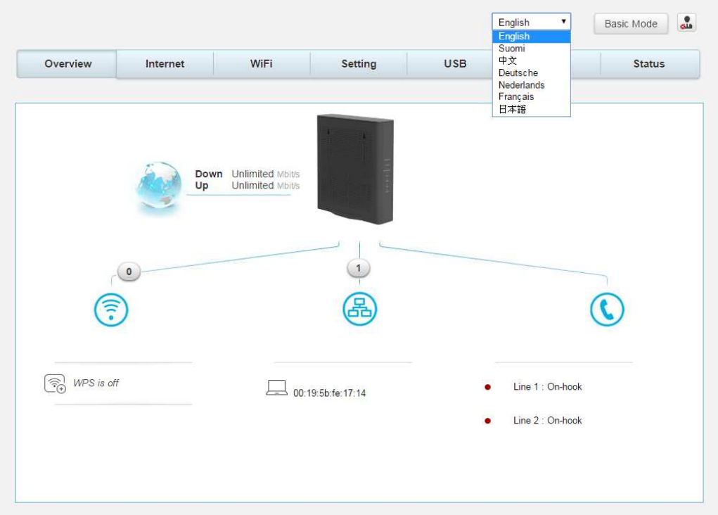
If you login successfully, the main page will appear.
You can change the display language to “English”, “Suomi”, “中文”, “ Deutsche”,
“Nederlands”, “Francais” or “日本語” on the top of the page.
Fig. 2-2 Switch Language
Overview Web Page Group
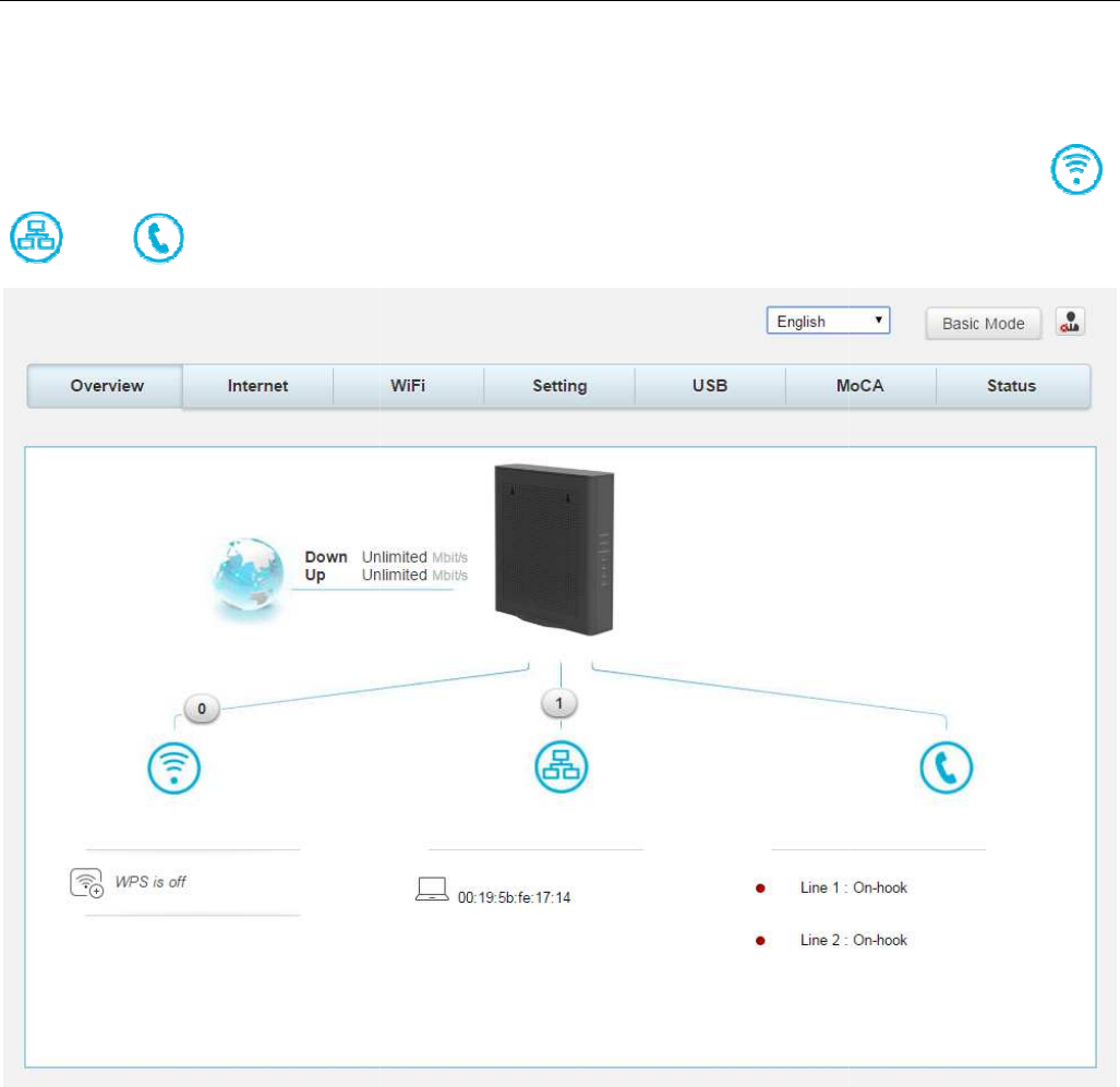
Overview
The Overview page is the start page. You could switch to other page
Setting, USB, MoCA, Status)
This page display Wi-Fi
, ETHERNET and VoIP connection status. You could click the icons
and will lead to Wi-
Fi
The Overview page is the start page. You could switch to other page
s
. (e.g.,
, ETHERNET and VoIP connection status. You could click the icons
Fi
, LAN and VoIP status pages.
Fig.2-3 Overview
Page 22 / 65
. (e.g.,
Internet, Wi-Fi,
, ETHERNET and VoIP connection status. You could click the icons
,
Page 23 / 65
Internet Web Page Group
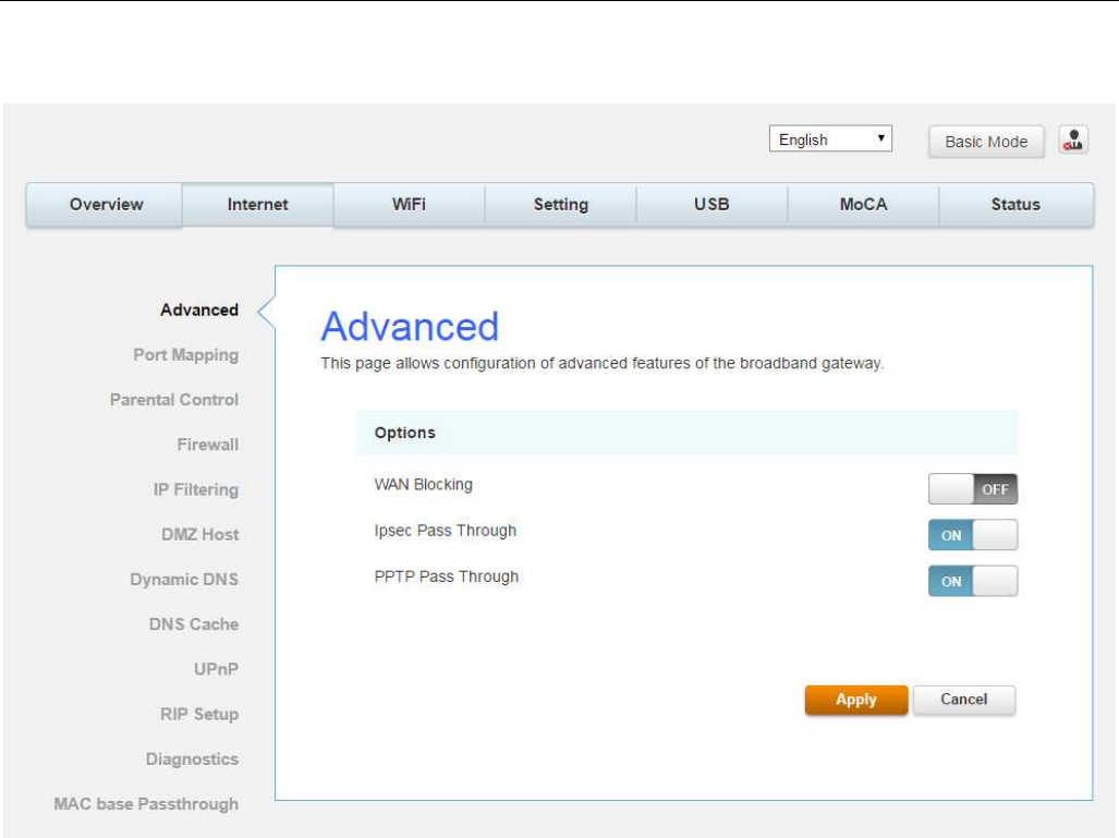
Advanced
This page allows you to enable/disable some advanced features of the Wireless Voice Gateway.
Fig.2-4 Internet\Advanced
WAN Blocking prevents others on the WAN side from being able to ping your gateway.
With WAN Blocking enabled, your gateway will not respond to pings it receives, effectively
“hiding” your gateway.
Ipsec PassThrough enables IpSec type packets to pass WAN LAN. IpSec (IP Security)
is a security mechanism used in Virtual Private Networks (VPNs).
PPTP PassThrough enables PPTP type packets to pass WAN LAN. PPTP (Point to Point
Tunneling Protocol) is another mechanism sometimes used in VPNs.
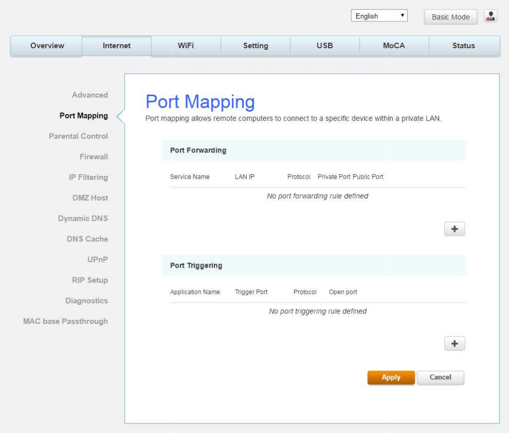
Port Mapping
This page allows configuration of
Port Forwarding For LAN
to originate an IP connection with a PC on the WAN; it will ignore attempts of the WAN PC
to originate a connection onto your PC. This protects you from malicious attacks from
outsiders. However, so
metimes you may wish for anyone outside to be able to originate a
connection to a particular PC on your LAN if the destination port (application) matches one
you specify.
Port Triggering
Some Internet activities, such as interactive gaming, require that a
the WAN side of your gateway be able to originate connections during the game with your
game playing PC on the LAN side. Port triggering is an elegant mechanism that does this
work for you, each time you play the game.
This page allows configuration of
Port Forwarding and Port Triggering.
Fig.2-5 Internet\Port Mapping
WAN communications, the gateway normally only allows you
to originate an IP connection with a PC on the WAN; it will ignore attempts of the WAN PC
to originate a connection onto your PC. This protects you from malicious attacks from
metimes you may wish for anyone outside to be able to originate a
connection to a particular PC on your LAN if the destination port (application) matches one
Some Internet activities, such as interactive gaming, require that a
the WAN side of your gateway be able to originate connections during the game with your
game playing PC on the LAN side. Port triggering is an elegant mechanism that does this
work for you, each time you play the game.
Page 24 / 65
WAN communications, the gateway normally only allows you
to originate an IP connection with a PC on the WAN; it will ignore attempts of the WAN PC
to originate a connection onto your PC. This protects you from malicious attacks from
metimes you may wish for anyone outside to be able to originate a
connection to a particular PC on your LAN if the destination port (application) matches one
Some Internet activities, such as interactive gaming, require that a
PC on
the WAN side of your gateway be able to originate connections during the game with your
game playing PC on the LAN side. Port triggering is an elegant mechanism that does this
Page 25 / 65
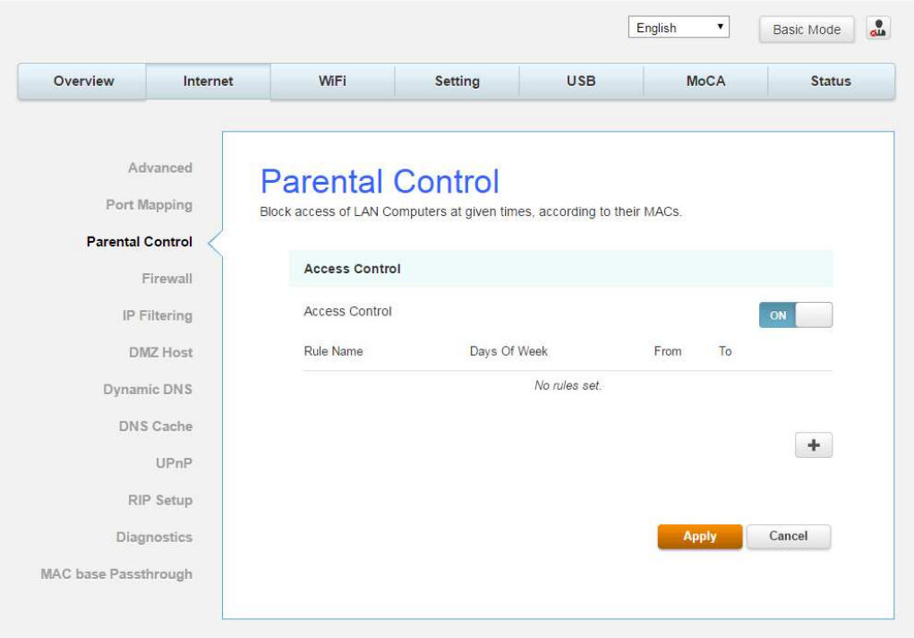
Parental Control
This page allows you to set the time limit for a client’s network usage.
Fig.2-6 Internet\Parental Control
Page 26 / 65
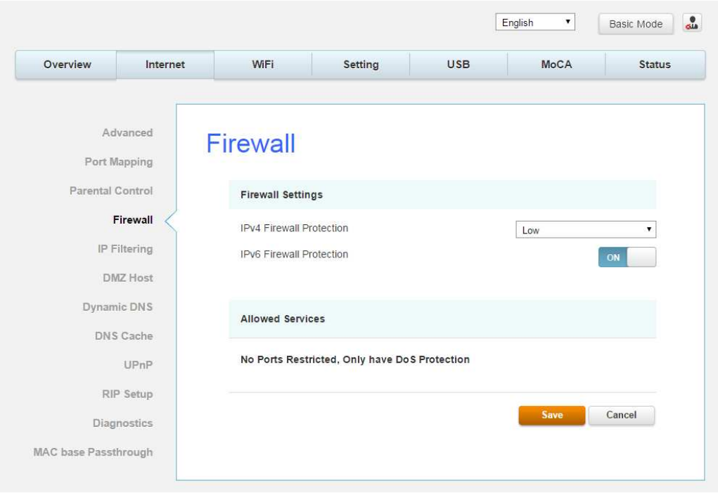
Firewall
This page allows you to enable/disable, and you can choose “Off”, “Low”, “Medium”, “High”
firewall protection.
The Low setting does not block any services/ports, however it does protect against invalid
packets and well known attacks. The Medium setting will cause the firewall to drop a packet
unless it is on a specific port of allowed services. The High setting is similar to medium, but
allows access to even fewer services. The Off setting allows all traffic to pass.
Fig.2-7 Internet\Firewall
Page 27 / 65
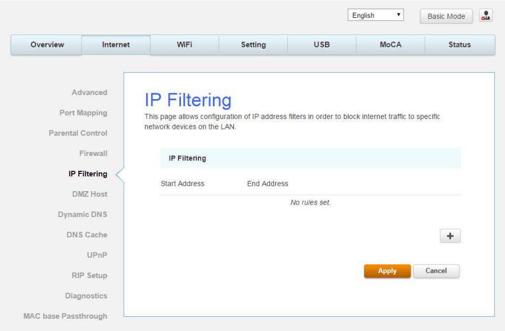
IP Filtering
This page enables you to enter the IP address ranges of PCs on your LAN that you don’t want
to have outbound access to the WAN. These PCs can still communicate with each other on your
LAN, but packets they send to WAN addresses are blocked by the gateway.
Fig.2-8 Internet\IP Filtering
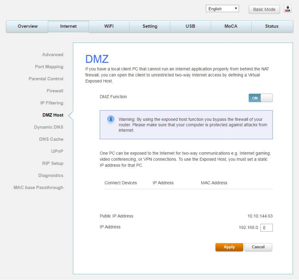
DMZ Host
Use this page to designate one PC on your LAN that should be left
WAN side, for all ports. e.g., if you put an HTTP server on this machine, anyone will be able to
access that HTTP server by using your gateway IP address as the destination.
Use this page to designate one PC on your LAN that should be left
accessible to all PCs from the
WAN side, for all ports. e.g., if you put an HTTP server on this machine, anyone will be able to
access that HTTP server by using your gateway IP address as the destination.
Fig.2-9 Internet\DMZ Host
Page 28 / 65
accessible to all PCs from the
WAN side, for all ports. e.g., if you put an HTTP server on this machine, anyone will be able to
access that HTTP server by using your gateway IP address as the destination.
Page 29 / 65
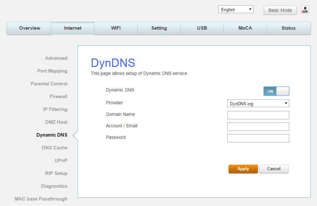
Dynamic DNS
This page allows to setup for Dynamic DNS server.
Fig.2-10 Internet\Dynamic DNS
Dynamic DNS- Turn “ON” to enable the dynamic DNS function.
Provider- Choose Provider to enable the basic setting.
Domain Name- The domain name that you registered with your DDNS provider.
Account / Email- The account that is registered with your DDNS provider.
Password- The password that you registered with your DDNS provider
Click Apply to save the changes.
Page 30 / 65
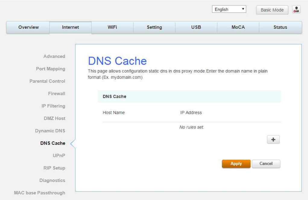
DNS Cache
This page allows configuration static DNS in DNS proxy mode. Enter the domain name in plain
format (Ex. mydomain.com)
Fig.2-11 Internet\DNS Cache
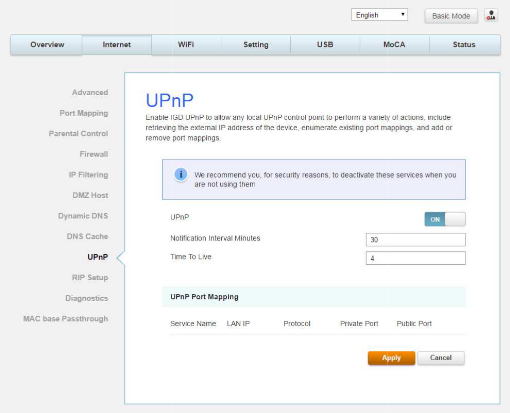
UPnP
Enable IGD UPnP to allow any local UPnP control point to perform a variety of actions, include
retrieving the external IP address of the device, enumerate existing port mappings, and add or
remove port mappings.
Enable IGD UPnP to allow any local UPnP control point to perform a variety of actions, include
retrieving the external IP address of the device, enumerate existing port mappings, and add or
Fig.2-12 Internet\UPnP
Page 31 / 65
Enable IGD UPnP to allow any local UPnP control point to perform a variety of actions, include
retrieving the external IP address of the device, enumerate existing port mappings, and add or
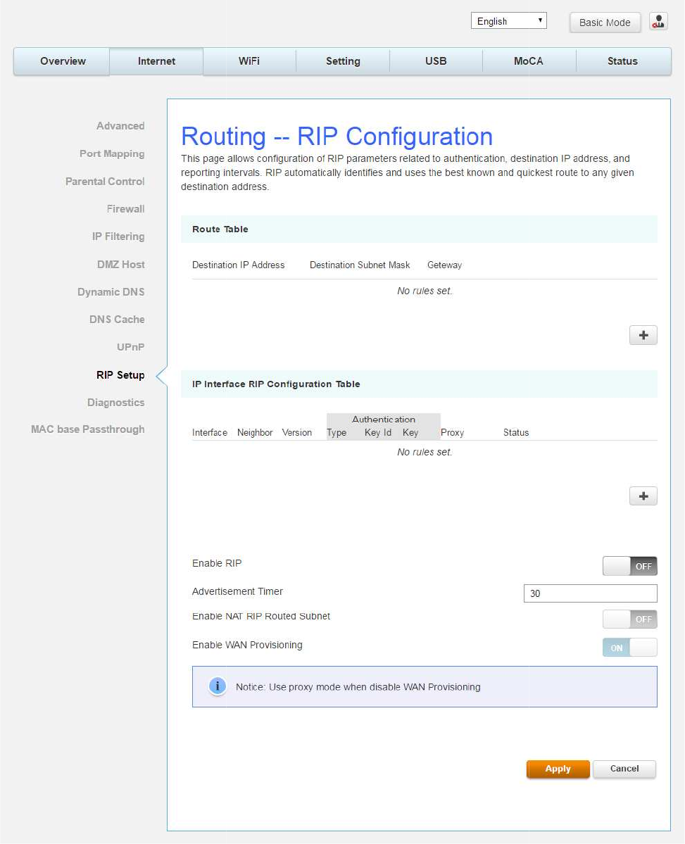
RIP Setup
This page allows configuration of RIP parameters related to authentication, destionation
address, and reporting intervals. RIP is used in WAN networks to identify and use the best
known and quickest route to given destination addresses to help reduce congestion and delays.
This page allows configuration of RIP parameters related to authentication, destionation
address, and reporting intervals. RIP is used in WAN networks to identify and use the best
known and quickest route to given destination addresses to help reduce congestion and delays.
Fig.2-13 Internet\RIP Setup
Page 32 / 65
This page allows configuration of RIP parameters related to authentication, destionation
IP
address, and reporting intervals. RIP is used in WAN networks to identify and use the best
known and quickest route to given destination addresses to help reduce congestion and delays.
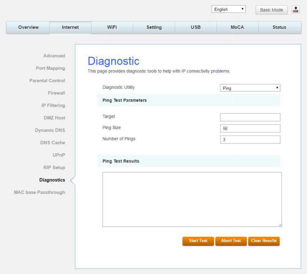
Diagnostic
This page offers basic diagnostic tools for you to
you
ping an Internet device, you send a packet to its TCP/IP stack, and it sends one back to
yours. To use
the ping Test, enter the information needed and press S
be displayed in the
lower part of the window. Press Abort Test to stop, and Clear Results to
clear the result contents.
Note: Firewalls may cause pings to fail but still provide you TCP/IP
access to selected devices behind
behind a firewall. Ping is most useful to
such as the PCs on your LAN side.
This page offers basic diagnostic tools for you to
use
when connectivity problems occur. When
ping an Internet device, you send a packet to its TCP/IP stack, and it sends one back to
the ping Test, enter the information needed and press S
tart Test; the Result will
lower part of the window. Press Abort Test to stop, and Clear Results to
Note: Firewalls may cause pings to fail but still provide you TCP/IP
access to selected devices behind
them.
Keep this in mind when ping a device that may be
behind a firewall. Ping is most useful to
verify connectivity with PCs which do not have firewalls,
such as the PCs on your LAN side.
Fig.2-14 Internet\Diagnostic
Page 33 / 65
when connectivity problems occur. When
ping an Internet device, you send a packet to its TCP/IP stack, and it sends one back to
tart Test; the Result will
lower part of the window. Press Abort Test to stop, and Clear Results to
Note: Firewalls may cause pings to fail but still provide you TCP/IP
Keep this in mind when ping a device that may be
verify connectivity with PCs which do not have firewalls,
Page 34 / 65
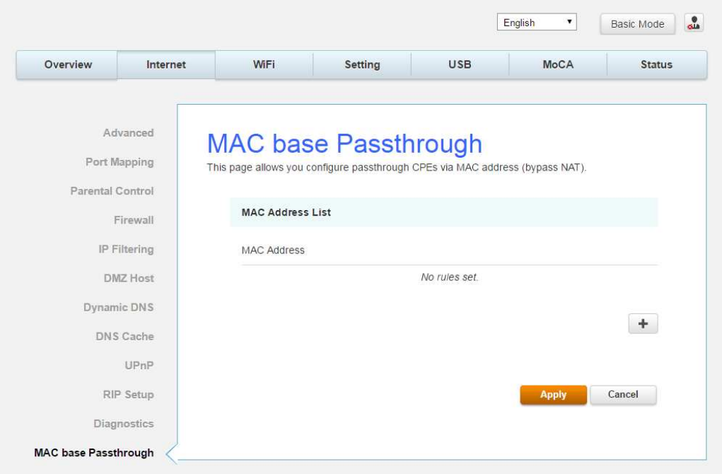
MAC base Passthrough
This page allows you configure passthrough CPEs via MAC address. (bypass NAT)
Fig.2-15 Internet\MAC base Passthrough
Page 35 / 65
Wi-Fi Web Page Group
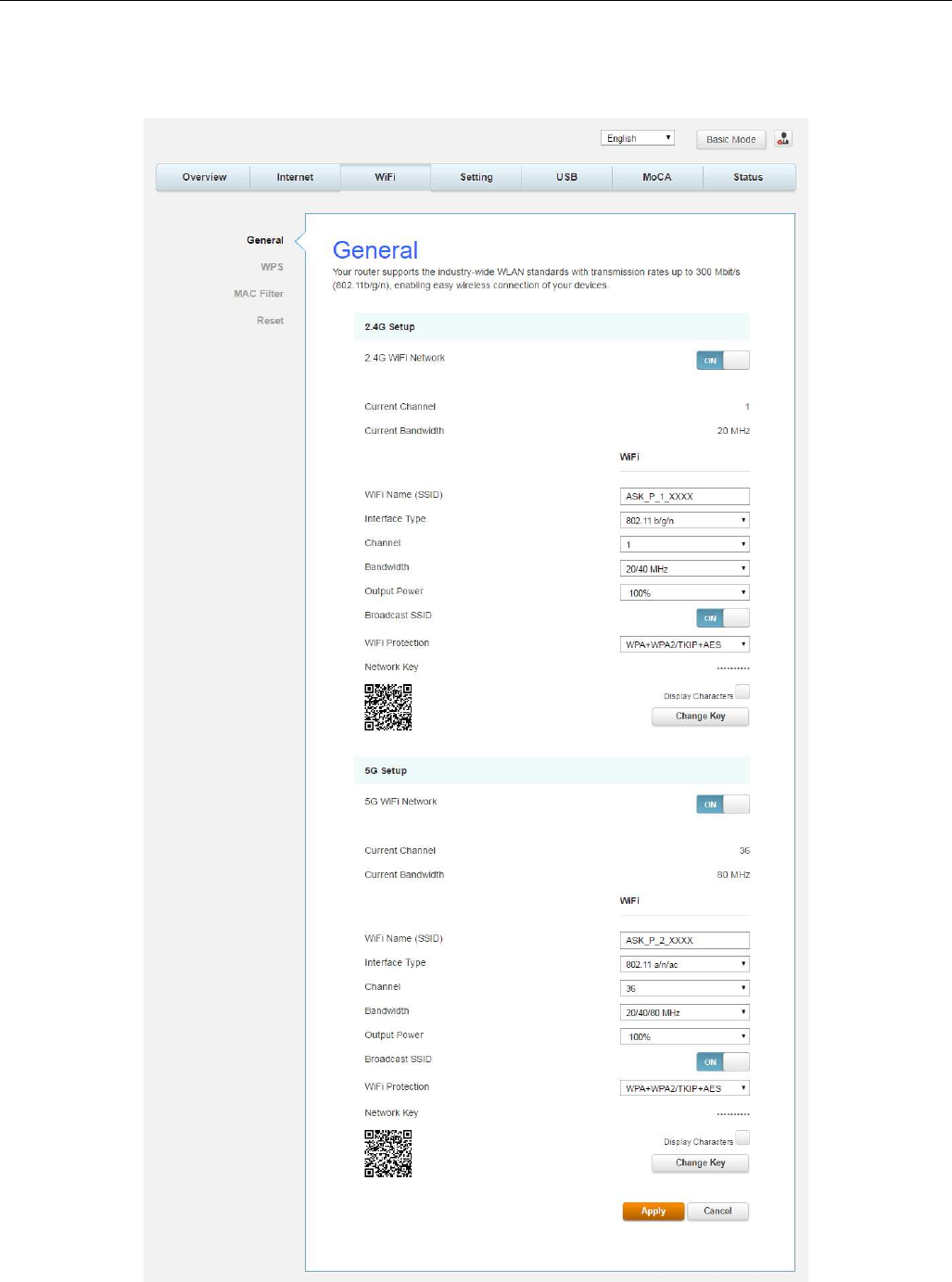
General
This page allows configuration of the 2.4GHz and 5GHz wireless features. These must match
the settings you make on your wireless-equipped PC on the LAN side.
Fig.2-16 Wi-Fi\General
Page 36 / 65
2.4GWi-Fi Network / 5GWi-Fi Network: It may help you to Enable or Disable the
2.4GHz / 5GHz wireless function.
Current Channel: The channel that you choose will be displayed in this field.
Current Bandwidth: The bandwidth that you choose will be displayed in this field.
Wi-Fi Name (SSID): The SSID for 2.4GHz / 5GHz wireless function.
Interface Type: There are three different modes can be selected. 2.4GHz can be
selected 802.11b/g, 802.11b/g/n and 802.11n only; 5GHz can be selected 802.11a,
802.11a/n/ac and 802.11n/ac only.
Channel: In 802.11 Band 2.4GHz, there are 1 to 11 channels. In 802.11 Band 5GHz,
there are 36, 40, 44, 48, 52, 56, 60, 64, 100, 104, 108, 112, 116, 120, 124, 128, 132,
136, 140, 144, 149, 153, 157, 161, 165 channels for all country. Choose the one that is
suitable for this device.
Bandwidth: Select wireless channel width 20/40 MHz is for 2.4GHz Wi-Fi default value,
and 20/40/80 MHz is for 5GHz Wi-Fi default value. (Bandwidth taken by wireless
signals of this access point.)
Output Power: This setting decides the output power of this device. You may use it to
economize on electricity by selecting lower percentage of power output. Control the
range of the AP by adjusting the radio output power.
Broadcast SSID: Broadcasting the SSID causes the name of your network to appear in
the list of available networks.
Wi-Fi Protection: The method of Wi-Fi protection can be OFF, WPA2/AES or
WPA+WPA2/TKIP+AES.
Network key: The network key is the password that you use to authenticate with your
router.
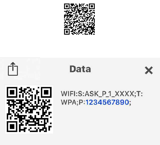
QR Code: Use the smart phone scan QR code APP to get Wi-Fi Name (SSID), Wi-Fi
Protection and Network key.
Page 37 / 65
Fig.2-17 Wi-Fi\General\QR Code
Fig.2-18 Wi-Fi\General\Scanning result
WIFI: S (SSID): ASK_P1_XXXX
T (Wi-Fi Protection): WPA
P (Network key): 1234567890

Page 38 / 65
802.11x Authentication introduction
If you enable the 802.11x authentication function, you will have to offer the following
information-
WEP-64 (Wired Equivalent Privacy):
WEP-64 is a simple security protocol for wireless networks that encrypts transmitted
data. The WEP key can be entered as a string of 10 hexadecimal characters (0–9 and
A–F).
WPA (Wi-Fi Protected Access)/WPA2:
It must be used in conjunction with an authentication server such as RADIUS to
provide centralized access control and management. It can provide stronger
encryption and authentication solution than none WPA modes. WPA2 is the second
generation of WPA security.
WPA/WPA2 Encryption:
There are two types that you can choose, AES, TKIP+AES.
TKIP takes the original master key only as a starting point and derives its
encryption keys mathematically from this mater key. Then it regularly changes
and rotates the encryption keys so that the same encryption key will never be
used twice
AES provides security between client workstations operating in ad hoc mode. It
uses a mathematical ciphering algorithm that employs variable key sizes of 128,
192 or 256 bits.
Page 39 / 65
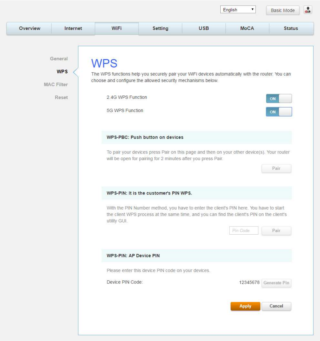
WPS
This page allows you to configure WPS setting. Wi-Fi Protected Setup
TM
(WPS) is an easy and secure
way
of configuring and connecting your Wireless access point. In this case, the Wireless Voice Gateway
is the
Access Point (AP), and your PC (or Wireless Device) is called the STA. When configuring your
Wireless
Network via WPS, messages are exchanged between the STA and AP in order to configure the
security
settings on both devices.
Fig.2-19 Wi-Fi\WPS
Page 40 / 65
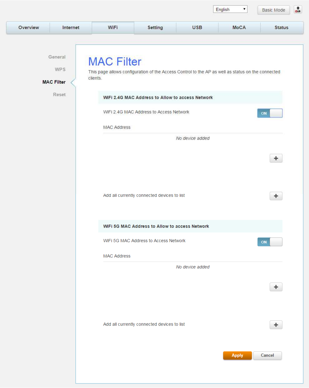
MAC Filter
By entering MAC Address, you can configure which local PCs are allowed access to the WAN.
Besides the list of MAC filter, any local PCs else would be blocked to the WAN.
Fig.2-20 Wi-Fi\MAC Filter
Page 41 / 65
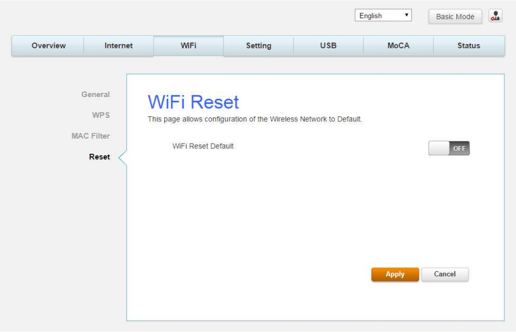
Reset
This page allows configuration of the wireless network to default.
Fig.2-21 Wi-Fi\Reset
Page 42 / 65
Settings Web Page Group
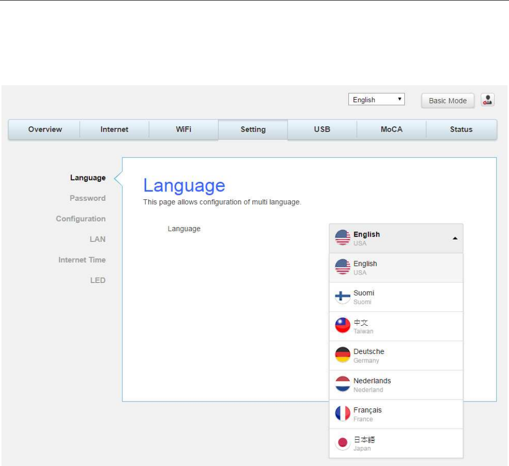
Language
This page allows configuration of language.
You can change the display language to “English”, “Suomi”, “中文”, “ Deutsche”, “Nederlands”,
“Francais” or “日本語” on the top of the page.
Fig.2-22 Setting\Language
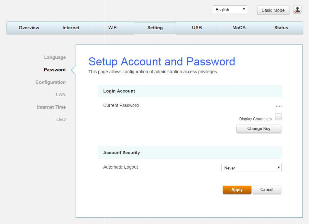
Password
By default, the username is "
user
When the current password is the default one, the user is strongly encouraged to change the
default web password.
The password can be a minimum of 8 characters, maximum of 20 characters and is case
sensitive. If forget your username and password, you may Press "Reset" button on the rear
panel more than 5seconds to restore the username and passwor
Note: We are always suggesting you to modify the password. This is a basic protection against
wrongful access to the Gateway Web pages.
user
" and password is "user".
When the current password is the default one, the user is strongly encouraged to change the
The password can be a minimum of 8 characters, maximum of 20 characters and is case
sensitive. If forget your username and password, you may Press "Reset" button on the rear
panel more than 5seconds to restore the username and passwor
d to default.
Note: We are always suggesting you to modify the password. This is a basic protection against
wrongful access to the Gateway Web pages.
Fig.2-23 Setting\Password
Page 43 / 65
When the current password is the default one, the user is strongly encouraged to change the
The password can be a minimum of 8 characters, maximum of 20 characters and is case
sensitive. If forget your username and password, you may Press "Reset" button on the rear
d to default.
Note: We are always suggesting you to modify the password. This is a basic protection against
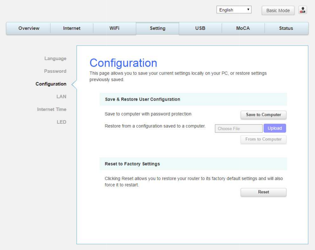
Configuration
This page allows you to save your current settings locally on
previously saved.
Save & Restore User Configuration
to Computer
and follow the prompts.
To restore a previous configuration, click
the file (usually backupsettings.conf
Computer
to restore the settings. Once the settings are restored, the device will reboot.
Reset to Factory Settings
default settings and will also force it to restart.
This page allows you to save your current settings locally on
your PC, or restore settings
Fig.2-24 Setting\Configuration
Save & Restore User Configuration
:
To back up the current configuration, click
and follow the prompts.
To restore a previous configuration, click
Upload
and use the navigation window to locate
the file (usually backupsettings.conf
.) Once the file has bee
n located, click
to restore the settings. Once the settings are restored, the device will reboot.
Reset to Factory Settings
: Click Reset
allows you to restore your router to factory
default settings and will also force it to restart.
Page 44 / 65
your PC, or restore settings
To back up the current configuration, click
Save
and use the navigation window to locate
n located, click
From to
to restore the settings. Once the settings are restored, the device will reboot.
allows you to restore your router to factory
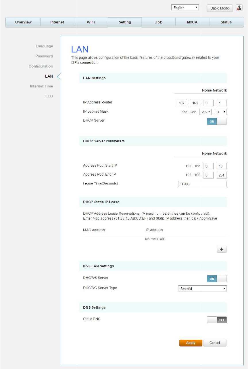
LAN
This page allows configuration of the basic features of the broadband gateway related to your
ISP’s connection.
This page allows configuration of the basic features of the broadband gateway related to your
Fig.2-25 Setting\LAN
Page 45 / 65
This page allows configuration of the basic features of the broadband gateway related to your
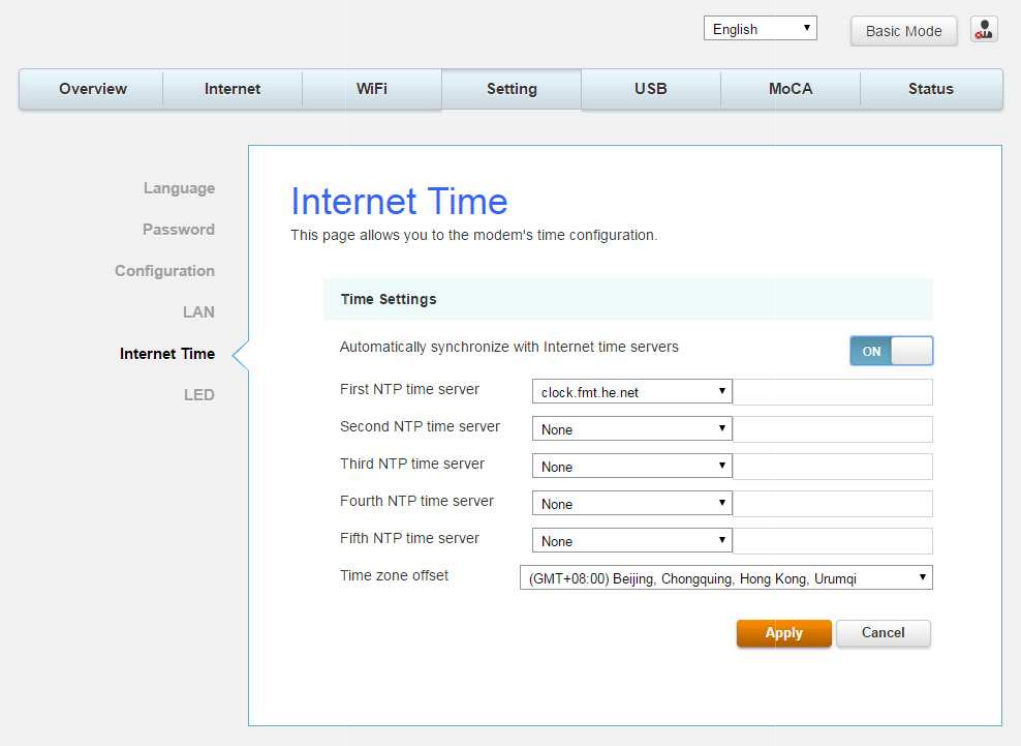
Internet Time
This page allows configuration and display of the system time obtained from network servers
via Simple Network Time Protocol. The system has to be reset for any changes to take effect.
This page allows configuration and display of the system time obtained from network servers
via Simple Network Time Protocol. The system has to be reset for any changes to take effect.
Fig.2-26 Setting\Internet Time
Page 46 / 65
This page allows configuration and display of the system time obtained from network servers
via Simple Network Time Protocol. The system has to be reset for any changes to take effect.
Page 47 / 65
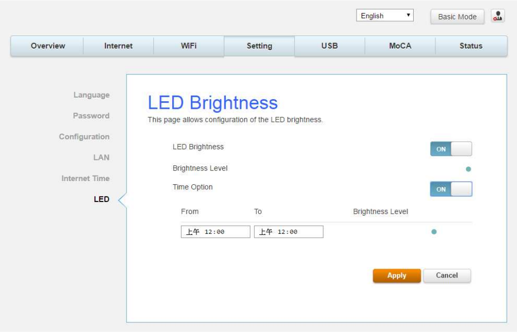
LED
This page allows configuration of the LED brightness.
Fig.2-27 Setting\LED
USB Web Page Group
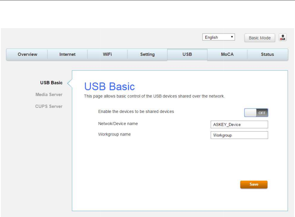
USB Basic
This page
allows basic control of the USB devices shared over the network.
allows basic control of the USB devices shared over the network.
Fig.2-28 USB\USB Basic
Page 48 / 65
allows basic control of the USB devices shared over the network.
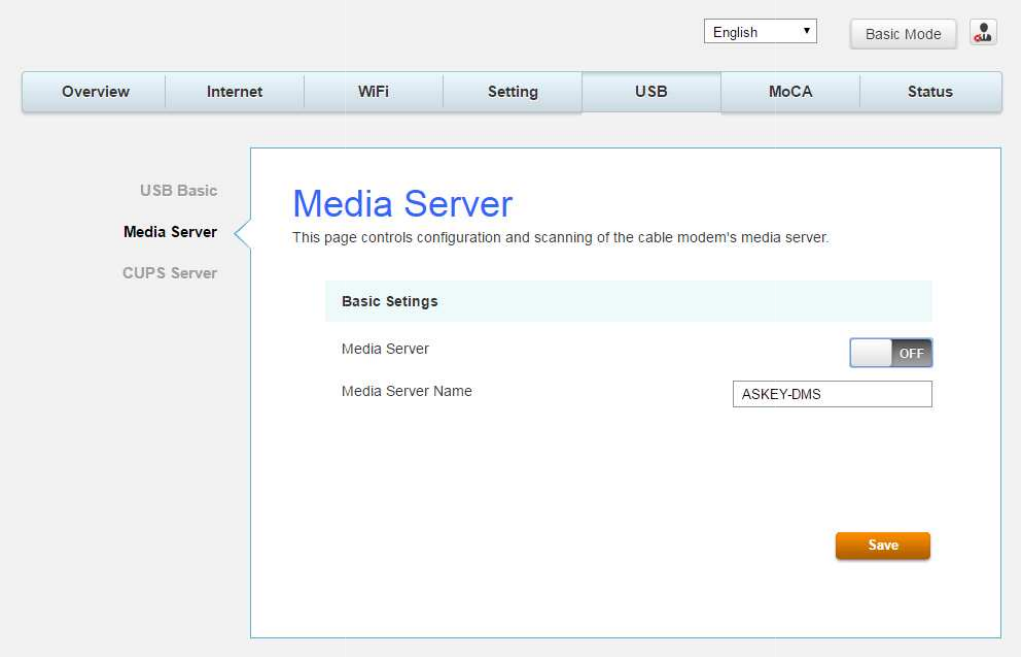
Media Server
This page
controls configuration
controls configuration
and scanning of the cable modem’
s media server.
Fig.2-29 USB\Media Server
Page 49 / 65
s media server.
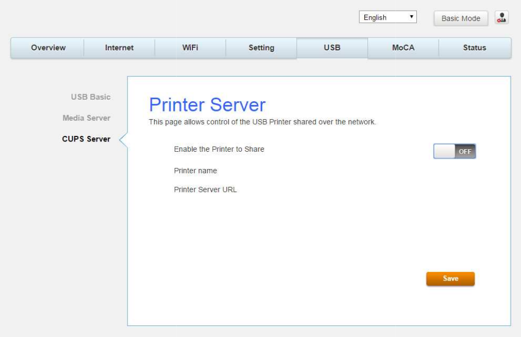
CPUS Server
This page
allows control of the USB
allows control of the USB
Printer shared over the network.
Fig.2-30 USB\CPUS Server
Page 50 / 65
Page 51 / 65
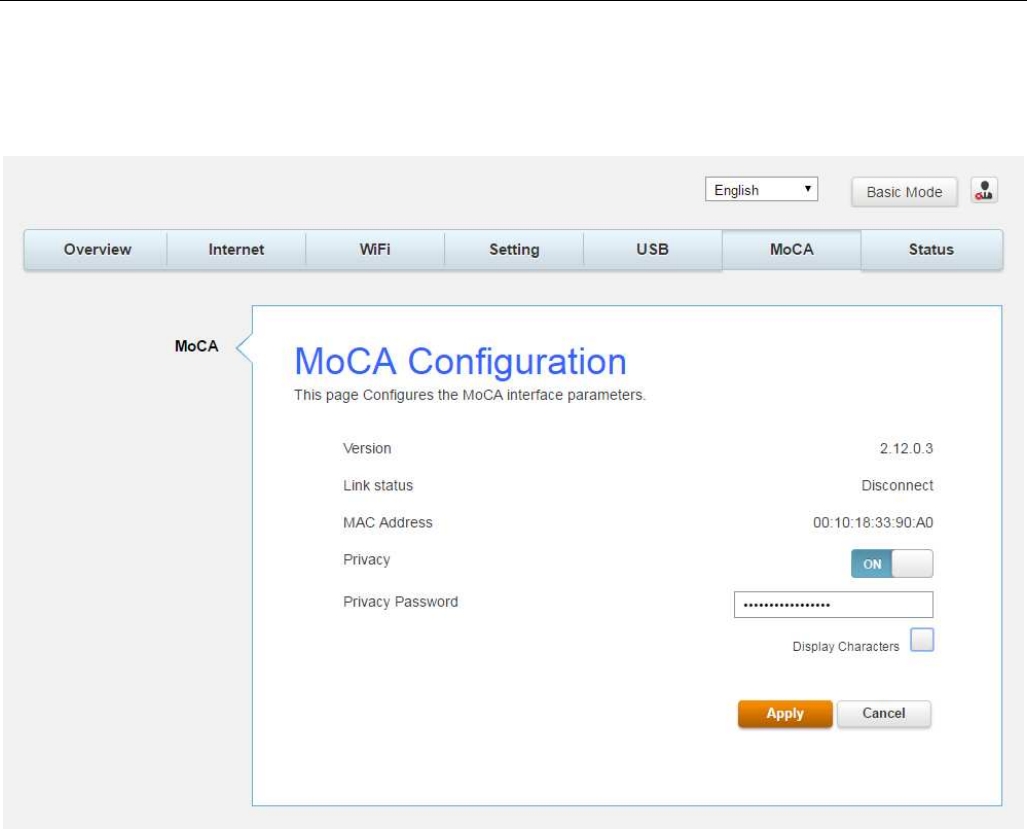
MoCA Web Page Group
MoCA
You will be able to change your MoCA setting here. MoCA is a new technology which utilizes
your existing CATV coax at home to form a home networking which will provide high speed
home network access.
Fig.2-31 MoCA\MoCA
Status Web Page Group
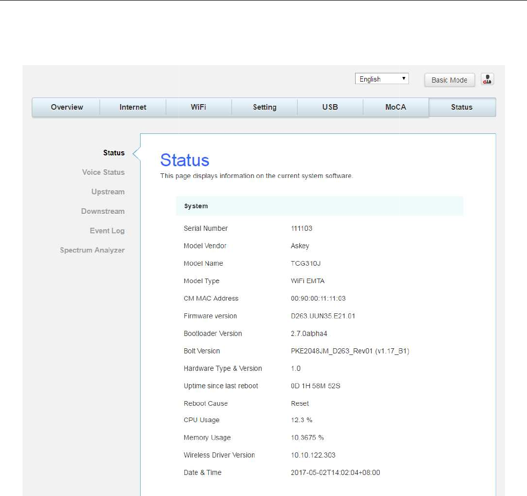
Status
This page can find an overview of all your router parameters. This may
or trouble shooting your router.
This page can find an overview of all your router parameters. This may
help you in optimizing
Fig.2-32 Status\Status
Page 52 / 65
help you in optimizing
Page 53 / 65
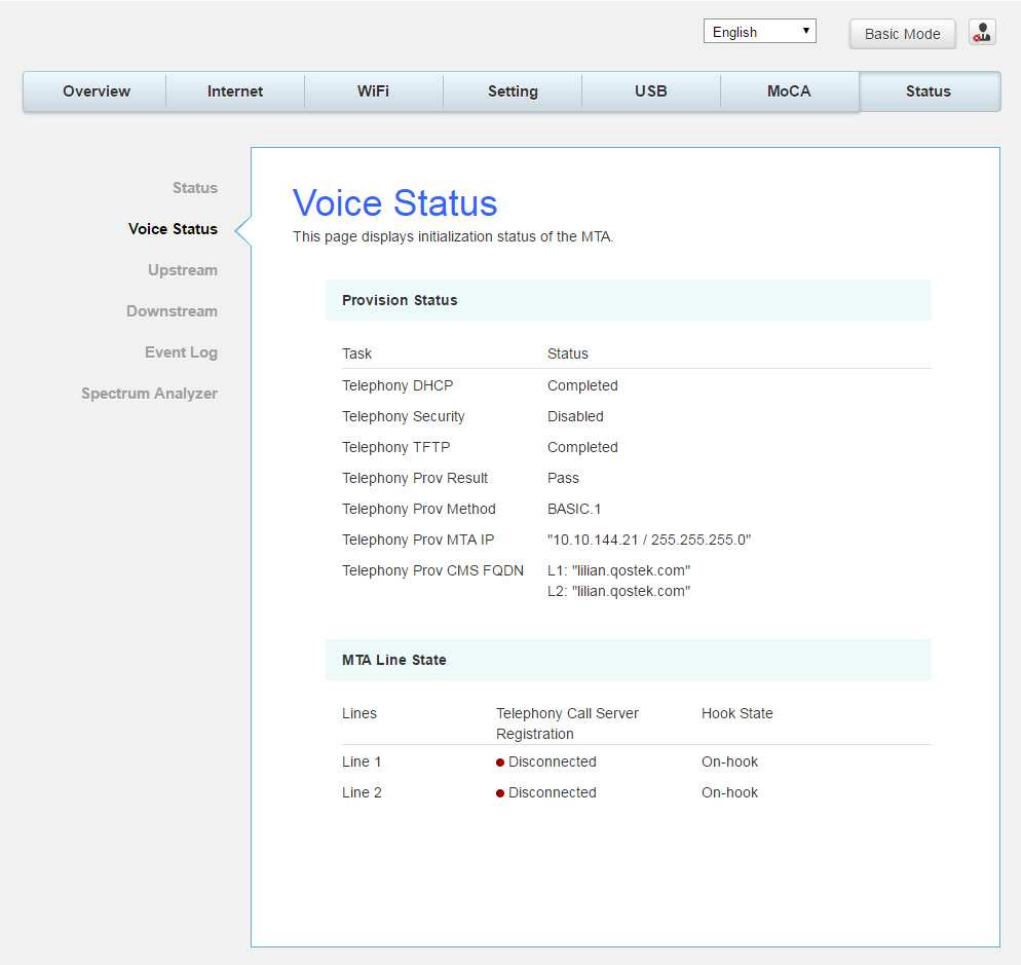
Voice Status
This page displays the initialization status of the MTA containing Telephony DHCP,
Security, TFTP and Provisioning Status. The information can be useful to your cable
company’s support technician if you’re having problems.
Fig.2-33 Status\Voice Status
Page 54 / 65
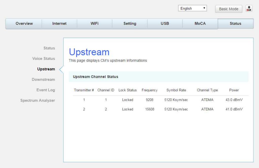
Upstream
This page reports current CM’s upstream information containing Transmitter #, Channel ID,
Lock Status, Frequency, Symbol Rate, Channel Type and Power. The information can be useful
to your cable company’s support technician if you’re having problems.
Fig. 2-34 Status\Upstream
Page 55 / 65
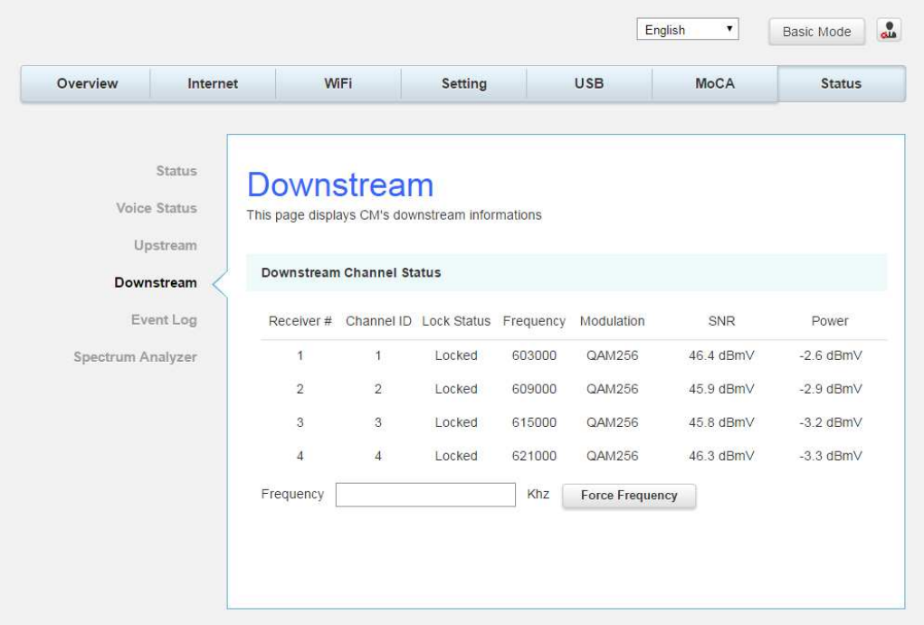
Downstream
This page reports current CM’s downstream information containing Receiver #, Channel ID,
Lock Status, Frequency, Modulation, SNR and Power. The information can be useful to your
cable company’s support technician if you’re having problems. By entering frequency in KHz and
clicking “Force frequency” button, you can force the CM locking to the specified frequency.
Fig. 2-35 Status\Downstream
Page 56 / 65
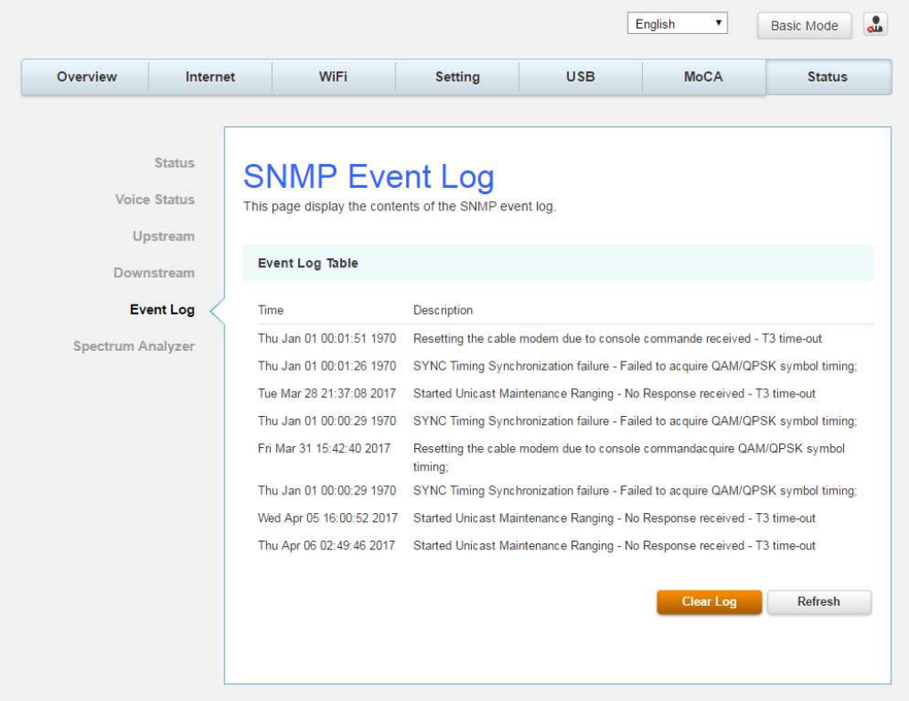
Event log
This page displays the contents of the SNMP event log.
Fig. 2-36 Status\Event log
Page 57 / 65
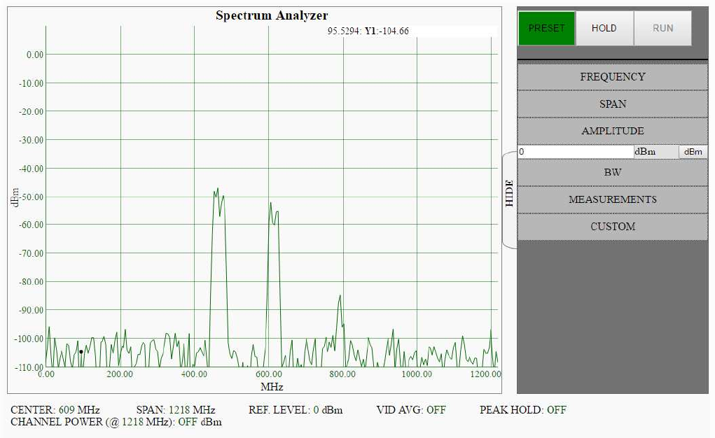
Spectrum Analyzer
This function can be accessed via click Spectrum Analyzer on GUI. The username is
"admin" and password is "aDm1n$TR8r ". The Spectrum Analyzer software enables the
user to configure an interactive GUI to study the RF characteristics on the cable modem. The
controls behave normally as they do on a regular spectrum analyzer.
Once the Run button is clicked, the cable modem starts collecting signal magnitude vs freq.
data.
Fig. 2-37 Status\Spectrum Analyzer

Page 58 / 65
CHAPTER 3: ADDITIONAL INFORMATION
Frequently Asked Questions
Q. How do I get the system installed?
A. Professional installation from your cable provider is strongly recommended. They will ensure
proper cable connection to the modem and your computer. However, your retailer may have
offered a self- installation kit, including the necessary software to communicate with your
cable ISP.
Q. Once my Cable Modem is connected, how do I get access to the Internet?
A. Your local cable company provides your internet service*, offering a wide range of services
including email, chat, and news and information services, and a connection to the World
Wide Web.
Q. Can I watch TV, surf the Internet, and talk to my friends through the Cable
Modem at the same
time?
A. Absolutely!
Q. What do you mean by “Broadband?”
A. Simply put, it means you’ll be getting information through a “bigger pipe,” with more
bandwidth, than a standard phone line can offer. A wider, “broader” band means more
information, more quickly.
Q. What is DOCSIS and what does it mean?
A. “Data over Cable Service Interface Specifications” is the industry standard that most cable
companies are adopting as they upgrade their systems. Should you ever decide to move, the
Cable Modem will work with all upgraded cable systems that are DOCSIS-compliant.
* Monthly subscription fee applies.
** Additional equipment required. Contact your Cable Company and ISP for any restrictions or
additional fees.

Page 59 / 65
General Troubleshooting
You can correct most problems you have with your product by consulting the troubleshooting
list that follows.
I can’t access the internet.
Check all of the connections to your Cable Modem.
Your Ethernet card may not be working. Check each product’s documentation for more
information.
The Network Properties of your operating system may not be installed correctly or the
settings may be incorrect. Check with your ISP or cable company.
I can’t get the modem to establish an Ethernet connection.
Even new computers don’t always have Ethernet capabilities – be sure to verify that your
computer has a properly installed Ethernet card and the driver software to support it.
Check to see that you are using the right type of Ethernet cable.
The modem won’t register a cable connection.
If the modem is in Initialization Mode, the INTERNET light will be flashing. Call your Cable
Company if it has not completed this 5-step process within 30 minutes, and note which
step it is getting stuck on.
The modem should work with a standard RG-6 coaxial cable, but if you’re using a cable
other than the one your Cable Company recommends, or if the terminal connections are
loose, it may not work. Check with your Cable Company to determine whether you’re using
the correct cable.
If you subscribe to video service over cable, the cable signal may not be reaching the
modem. Confirm that good quality cable television pictures are available to the coaxial
connector you are using by connecting a television to it. If your cable outlet is “dead”, call
your Cable Company.
Verify that the Cable Modem service is DOCSIS compliant by calling your cable provider.

Page 60 / 65
Service Information
If you purchased or leased your Cable Modem directly from your cable company, then warranty
service for the Digital Cable Modem may be provided through your cable provider or its
authorized representative. For information on 1) Ordering Service, 2) Obtaining Customer
Support, or 3) Additional Service Information, please contact your cable company. If you
purchased your Cable Modem from a retailer, see the enclosed warranty card.

Page 61 / 65
Federal Communication Commission Interference Statement
This device complies with Part 15 of the FCC Rules. Operation is subject to the following two
conditions: (1) This device may not cause harmful interference, and (2) this device must accept
any interference received, including interference that may cause undesired operation.
This equipment has been tested and found to comply with the limits for a Class B digital device,
pursuant to Part 15 of the FCC Rules. These limits are designed to provide reasonable
protection against harmful interference in a residential installation. This equipment generates,
uses and can radiate radio frequency energy and, if not installed and used in accordance with
the instructions, may cause harmful interference to radio communications. However, there is
no guarantee that interference will not occur in a particular installation. If this equipment does
cause harmful interference to radio or television reception, which can be determined by turning
the equipment off and on, the user is encouraged to try to correct the interference by one of
the following measures:
- Reorient or relocate the receiving antenna.
- Increase the separation between the equipment and receiver.
- Connect the equipment into an outlet on a circuit different from that
to which the receiver is connected.
- Consult the dealer or an experienced radio/TV technician for help.
FCC Caution: Any changes or modifications not expressly approved by the party responsible for
compliance could void the user's authority to operate this equipment.
This transmitter must not be co-located or operating in conjunction with any other antenna or
transmitter.
For operation within 5.15 5.25GHz / 5.47 5.725GHz frequency range, it is restricted to indoor
environment. This device meets all the other requirements specified in Part 15E, Section
15.407 of the FCC Rules.
Page 62 / 65
FOR MOBILE DEVICE USAGE (>28cm/low power)
Radiation Exposure Statement:
This equipment complies with FCC radiation exposure limits set forth for an uncontrolled
environment. This equipment should be installed and operated with minimum distance 28cm
between the radiator & your body.
FOR COUNTRY CODE SELECTION USAGE (WLAN DEVICES)
Note: The country code selection is for non-US model only and is not available to all US model.
Per FCC regulation, all Wi-Fi products marketed in US must fix to US operation channels only.

Page 63 / 65
Industry Canada statement:
This device complies with ISED’s licence-exempt RSSs. Operation is subject to the following two
conditions: (1) This device may not cause harmful interference, and (2) this device must accept
any interference received, including interference that may cause undesired operation.
Le présent appareil est conforme aux CNR d’ ISED applicables aux appareils radio exempts de
licence. L’exploitation est autorisée aux deux conditions suivantes : (1) le dispositif ne doit pas
produire de brouillage préjudiciable, et (2) ce dispositif doit accepter tout brouillage reçu, y
compris un brouillage susceptible de provoquer un fonctionnement indésirable.
Caution :
(i) the device for operation in the band 5150-5250 MHz is only for indoor use to reduce the
potential for harmful interference to co-channel mobile satellite systems;
(ii) the maximum antenna gain permitted for devices in the bands 5250-5350 MHz and 5470-
5725 MHz shall be such that the equipment still complies with the e.i.r.p. limit;
(iii) the maximum antenna gain permitted for devices in the band 5725-5850 MHz shall be such
that the equipment still complies with the e.i.r.p. limits specified for point-to-point and non-
point-to-point operation as appropriate; and
(v) Users should also be advised that high-power radars are allocated as primary users (i.e.
priority users) of the bands 5250-5350 MHz and 5650-5850 MHz and that these radars could
cause interference and/or damage to LE-LAN devices.
Avertissement:
Le guide d’utilisation des dispositifs pour réseaux locaux doit inclure des instructions précises
sur les restrictions susmentionnées, notamment :
(i) les dispositifs fonctionnant dans la bande 5150-5250 MHz sont réservés uniquement pour
une utilisation à l’intérieur afin de réduire les risques de brouillage préjudiciable aux systèmes
de satellites mobiles utilisant les mêmes canaux;
(ii) le gain maximal d'antenne permis pour les dispositifs utilisant les bandes de 5250 à 5 350
MHz et de 5470 à 5725 MHz doit être conforme à la limite de la p.i.r.e;
(iii) le gain maximal d'antenne permis (pour les dispositifs utilisant la bande de 5 725 à 5 850
MHz) doit être conforme à la limite de la p.i.r.e. spécifiée pour l'exploitation point à point et
l’exploitation non point à point, selon le cas;
Page 64 / 65
(v) De plus, les utilisateurs devraient aussi être avisés que les utilisateurs de radars de haute
puissance sont désignés utilisateurs principaux (c.-à-d., qu’ils ont la priorité) pour les bandes
5250-5350 MHz et 5650-5850 MHz et que ces radars pourraient causer du brouillage et/ou des
dommages aux dispositifs LAN-EL.
FOR MOBILE DEVICE USAGE (>28cm/low power)
Radiation Exposure Statement:
This equipment complies with ISED radiation exposure limits set forth for an uncontrolled
environment. This equipment should be installed and operated with minimum distance 28cm
between the radiator & your body.
Déclaration d'exposition aux radiations:
Cet équipement est conforme aux limites d'exposition aux rayonnements ISED établies pour un
environnement non contrôlé. Cet équipement doit être installé et utilisé avec un minimum de 28
cm de distance entre la source de rayonnement et votre corps.

Page 65 / 65
CAUTION for UL (Check caution label on gift box)
North American Cable Installer:
This reminder is provided to call your attention to Article 820.93 of the National Electrical Code
(Section 54 of the Canadian Electrical Code, Part 1) which provides guidelines for proper
grounding and, in particular, specifies that the cable ground shall be connected to the
grounding system of the building as close to the point of cable entry as practical.