Atlas Copco BLM STA6K Data analyser User Manual
Atlas Copco BLM Data analyser
User Manual
User Guide
STa 6000
Atlas Copco Industrial Technique AB
9836 8243 01
2016-06
Edition 3.1

STa 6000 User Guide Revision history
9836 8243 01 Edition 3.1 3 (324)
Revision history
Edition Date Author Description
Reference
Minimum
Software version
(ToolsTalk BLM)
Reference
Firmware
version
1.0 17 April 2014 M. Grippa First issue 8.0.x 1.0
2.0 15 July 2014 M. Grippa General manual update 8.0.x 1.0x
2.1 01 October
2014
M. Grippa Free test added (par. 6.1), Identifier
updated (par. 11), Display layout updated 8.1.x 1.1x
2.2 04 February
2015
M. Grippa RBU AA added, Statistics and reports
updated, Test execution window updated,
Pset programming updated (par. 7.1),
Settings updated (par. 16), EAP-TLS
security type added (par. 21), transducer
management updated, MRTT-C firmware
update added
8.3.x 2.0x
2.3 21 May 2015 M. Grippa FCC Certification added (par. 1.5), Power
Focus Calibration updated (par. 10.1),
PowerMACS Calibration updated (par.
10.2), Other Controller Calibration updated
(par. 10.3), Text Execution updated (par.
17.2), Execute the Pset (par. 7.2.1), STa
6000 text editing added (par. 3.3), Only
angle strategy added (par. 8.2.2)
8.4.x 2.1x
2.4 21 July 2015 C. Pacente Main parameters and control strategy
updated (par. 7.1.1), Batch parameters
updated (par. 7.1.5), Cm/Cmk (ISO -
CNOMO) statistics updated (par. 14.1.2),
Cm/Cmk (ISO - CNOMO) report updated
(par. 14.2.2), Real time statistics on the
STa 6000 display updated (par. 14.4.1),
CNOMO standard E41.32.110N added
(par. 14.4.2), Controller Configuration
updated (par. 16.1)
8.5.x 2.2x

Revision history STa 6000 User Guide
4 (324) 9836 8243 01 Edition 3.1
Edition Date Author Description
Reference
Minimum
Software version
(ToolsTalk BLM)
Reference
Firmware
version
2.5 11 November
2015
C. Pacente EC Declaration of Conformity updated
(par.1.4), MET Certification added (par.
1.5), Battery Charger updated (par.
2.3.5.1), Mini USB Port updated (par. 3.6),
Main parameters and control strategy
updated (par. 7.1.1), Torque parameters
updated (par. 7.1.2), Angle parameters
updated (par. 7.1.3), Time updated (par.
7.1.4), Pulse parameters updated (par.
7.1.5), Options updated (par. 7.1.6),
Subgroup parameters added (par. 7.1.7),
Results Notes option updated (par. 7.2.2),
Results Viewer updated (par. 12),
Cm/Cmk (ISO - CNOMO) report updated
(par. 14.1.2), Cm/Cmk (Shifting samples)
added (par. 14.4.2.2), Offline
Programming updated (par. 15
),
Controller configuration updated (par.
16.1), Test execution window
customization updated (par. 16.9)
8.6.x 2.3x
3.0 17 March
2016
C. Pacente Specifications updated (par. 1.3), FCC
Rules added (par. 1.5), STa 6000
Versions updated (par. 2.1), Presentation
updated (par. 2.3), IRC-W / IRC-B radio
modules updated (par. 2.3.4), Software
installation updated (par. 4.1), Software
registration updated (par. 4.1.1), ToolsTalk
BLM Overview updated (par. 4.2), STa
6000 Map updated (par. 4.2.4),
Transducers updated (par. 5), Non-ACTA
Transducers Database updated (par. 5.1),
ACTA Transducers Information updated
(par. 5.2), Pset updated (par. 7), Tools
Testing updated (par. 8), Calibration
Report updated (par. 10.4), Identifier
updated (par. 11), Identifier Concepts
updated (par. 11.1), Configuring a work
order updated (par. 11.3.2), Configuring
result parts updated (par. 11.3.3), Printing
identifiers strings updated (par. 11.3.4),
9.0.x 3.0x

STa 6000 User Guide Revision history
9836 8243 01 Edition 3.1 5 (324)
Edition Date Author Description
Reference
Minimum
Software version
(ToolsTalk BLM)
Reference
Firmware
version
Scanning barcodes with STa 6000
updated (par. 11.4), View one trace
updated (par. 13.1), Traces comparison
updated (par. 13.2), Copy, Print and
Export traces updated (par. 13.3), STa
6000 settings updated (par. 16), Controller
configuration updated (par. 16.1),
Information updated (par. 16.2), IRC-C
added (par. 16.4), SPC Rules updated
(par. 16.6), Memory updated (par. 16.7),
Working with IRC-Connect (and relative
sub-paragraphs) added (par. 18),
Troubleshooting Guide updated (par. 23)
3.1 14 June 2016 C. Pacente Specifications updated (par. 1.3), EC
Declaration of Conformity updated (par.
1.4), FCC Rules updated (par. 1.5),
Transducers updated (par. 5), Saving
Psets (from STa 6000 to PC) added (par.
7.3), PowerMACS calibration updated (par.
10.2), STa 6000 communication method
settings Manual / Serial communication
(Mode 1 ÷ 50) added (par. 10.2.1), STa
6000 communication method settings
Serial communication (Mode 0) added (par.
10.2.2), Identifier Prerequisites and Details
updated (par. 11.2)
9.1.x 3.1x
Copyright Atlas Copco Industrial Technique AB
NOTE: This manual may be altered without further notice.
For further information log on to the Atlas Copco website: www.atlascopco.com
NOTE:
The programming software (ToolsTalk BLM) may be updated with no changes about
the STa 6000 functionalities. The minimum software version indicated here is required for the
reference firmware version.
NOTE: In the event of conflicts between translations of this User Guide, always refer to the
official English version.

Table of Contents STa 6000 User Guide
6 (324) 9836 8243 01 Edition 3.1
Table of Contents
Table of Contents ............................................................................................................ 6
BATTERY INFORMATION according to European regulation 2006/66/EC ...................... 12
1 INTRODUCTION ............................................................................................................. 13
1.1 About this Document .............................................................................................. 13
1.2 Reference Documents ............................................................................................ 15
1.3 Specifications ......................................................................................................... 15
1.4 EC Declaration of Conformity ................................................................................. 21
1.5 FCC Rules .............................................................................................................. 22
2 SYSTEM OVERVIEW ...................................................................................................... 23
2.1 STa 6000 Versions ................................................................................................. 24
2.1.1 Basic ........................................................................................................................ 25
2.1.2 QC (Quality Control) ................................................................................................ 25
2.1.3 AA (Advanced Analysis) .......................................................................................... 26
2.2 STa 6000 Typical Applications Scenario ................................................................. 26
2.2.1 Stand-alone STa 6000 ............................................................................................. 26
2.2.2 STa 6000 connected to Torque Supervisor ............................................................. 27
2.3 Presentation ........................................................................................................... 28
2.3.1 STa 6000 assembly ................................................................................................. 31
2.3.2 RBU ......................................................................................................................... 32
2.3.3 QAT Barcode reader ................................................................................................ 34
2.3.4 IRC-W / IRC-B radio modules.................................................................................. 35
2.3.5 Battery ...................................................................................................................... 36
2.3.5.1 Battery Charger .......................................................................................... 36
2.3.6 External power supply ............................................................................................. 38
2.3.7 SRTT-L .................................................................................................................... 38
3 USER INTERFACES ....................................................................................................... 42
3.1 Connector ............................................................................................................... 42
3.2 Display.................................................................................................................... 43
3.3 Keyboard ................................................................................................................ 44
3.4 Buzzer .................................................................................................................... 45
3.5 Network Port ........................................................................................................... 45
3.6 Mini USB Port ......................................................................................................... 45
4 WORKING WITH ToolsTalk BLM ................................................................................... 46
4.1 Software Installation ............................................................................................... 47
4.1.1 Software registration ................................................................................................ 51
4.1.2 Software upgrade .................................................................................................... 51
4.2 ToolsTalk BLM Overview ........................................................................................ 52
4.2.1 Menu list ................................................................................................................... 53
4.2.2 Toolbar ..................................................................................................................... 54

STa 6000 User Guide Table of Contents
9836 8243 01 Edition 3.1 7 (324)
4.2.3 Status bar ................................................................................................................ 55
4.2.4 STa 6000 Map ......................................................................................................... 55
4.3 Settings in ToolsTalk BLM ...................................................................................... 56
4.4 Connecting to the STa 6000 ................................................................................... 56
4.4.1 USB connection ....................................................................................................... 57
4.4.2 Ethernet connection ................................................................................................. 58
4.5 Enabling LOG File .................................................................................................. 61
4.6 Saving Programs (from STa 6000 to PC) ............................................................... 62
5 TRANSDUCERS ............................................................................................................. 64
5.1 Non-ACTA Transducers Database ......................................................................... 66
5.1.1 Adding a transducer to the database ...................................................................... 66
5.1.2 Selecting the transducer for the test ........................................................................ 68
5.1.3 Transducer information ............................................................................................ 70
5.2 ACTA Transducers Information .............................................................................. 71
6 GETTING STARTED WITH STa 6000 ............................................................................ 73
6.1 Executing a Free Test ............................................................................................ 75
6.2 Executing a Quick Test .......................................................................................... 76
7 PSET............................................................................................................................... 79
7.1 Programming a Pset .............................................................................................. 79
7.1.1 Main parameters and control strategy ..................................................................... 83
7.1.2 Torque parameters .................................................................................................. 85
7.1.3 Angle parameters .................................................................................................... 88
7.1.4 Time ......................................................................................................................... 89
7.1.5 Pulse parameters .................................................................................................... 91
7.1.6 Options .................................................................................................................... 92
7.1.7 Subgroup parameters .............................................................................................. 93
7.2 Running a Pset....................................................................................................... 97
7.2.1 Execute the Pset ..................................................................................................... 97
7.2.2 Results Notes option ............................................................................................. 100
7.2.3 Customize the Pset execution window .................................................................. 101
7.2.4 View on-screen traces ........................................................................................... 102
8 TOOLS TESTING ......................................................................................................... 103
8.1 Click-Wrenches Testing ....................................................................................... 109
8.1.1 Test setup for click-wrench test ............................................................................. 111
8.1.1.1 Measure delay time ................................................................................. 111
8.1.1.2 Reset time ................................................................................................ 112
8.1.1.3 End cycle time ......................................................................................... 112
8.1.1.4 Slip Torque .............................................................................................. 113
8.1.1.5 Direction (CW/CCW)................................................................................ 113
8.1.1.6 Filter frequency (Fcut).............................................................................. 113
8.1.1.7 Unit........................................................................................................... 113
8.2 Power Tools Testing ............................................................................................ 114
8.2.1 Test setup for power tool test ................................................................................ 116
8.2.1.1 Measure delay time ................................................................................. 116

Table of Contents STa 6000 User Guide
8 (324) 9836 8243 01 Edition 3.1
8.2.1.2 Reset time ................................................................................................ 116
8.2.1.3 End cycle time .......................................................................................... 117
8.2.1.4 Filter frequency (Fcut) .............................................................................. 117
8.2.1.5 Direction (CW/CCW) ................................................................................ 117
8.2.1.6 Unit ........................................................................................................... 117
8.2.2 Angle Test .............................................................................................................. 118
8.3 Peak Wrench Testing ........................................................................................... 119
8.3.1 Test setup for peak wrench test............................................................................. 120
8.3.1.1 End cycle time .......................................................................................... 120
8.3.1.2 Filter frequency (Fcut) .............................................................................. 121
8.3.1.3 Direction (CW/CCW) ................................................................................ 121
8.3.1.4 Unit ........................................................................................................... 121
8.4 Pulse Tools Testing .............................................................................................. 122
8.4.1 Test setup for Pulse Tool test ................................................................................ 125
8.4.1.1 End cycle time .......................................................................................... 125
8.4.1.2 Torque coefficient .................................................................................... 126
8.4.1.3 Filter frequency (Fcut) .............................................................................. 127
8.4.1.4 Direction (CW/CCW) ................................................................................ 127
8.4.1.5 Minimum pulse and maximum pulse ....................................................... 128
8.4.1.6 Unit ........................................................................................................... 128
8.4.1.7 Threshold ................................................................................................. 128
8.4.2 Test setup for ACTA Pulse Tool test ..................................................................... 128
8.4.2.1 Measure delay time.................................................................................. 128
8.4.2.2 Reset time ................................................................................................ 129
8.4.2.3 End cycle time .......................................................................................... 130
8.4.2.4 Filter frequency (Fcut) .............................................................................. 130
8.4.2.5 Direction (CW/CCW) ................................................................................ 130
8.4.2.6 Minimum pulse and maximum pulse ....................................................... 130
8.4.2.7 Unit ........................................................................................................... 130
9 JOINTS TESTING ......................................................................................................... 131
9.1.1 Yield Point (JOINT ANALYSIS) ............................................................................. 131
9.1.2 Residual Torque/Time ........................................................................................... 134
9.1.2.1 Breakaway detection algorithm ................................................................ 135
9.1.3 Residual Torque/Angle .......................................................................................... 137
9.1.3.1 Breakaway detection algorithm ................................................................ 140
9.1.4 Residual Torque/Peak ........................................................................................... 142
9.1.5 Loose and Re-tight ................................................................................................ 144
10 POWER FOCUS, PowerMACS AND GENERIC CONTROLLER CALIBRATION ........ 145
10.1 Power Focus calibration ....................................................................................... 145
10.2 PowerMACS calibration ........................................................................................ 154
10.2.1 STa 6000 communication method settings Manual / Serial communication
(Mode 1 ÷ 50) ......................................................................................................... 155
10.2.2 STa 6000 communication method settings Serial communication (Mode 0) ..... 160
10.3 Other Controller Calibration .................................................................................. 164
10.4 Calibration Report ................................................................................................. 168

STa 6000 User Guide Table of Contents
9836 8243 01 Edition 3.1 9 (324)
11 IDENTIFIER .................................................................................................................. 170
11.1 Identifier Concepts ............................................................................................... 171
11.2 Identifier Prerequisites and Details ....................................................................... 172
11.3 Configuration of Identifier Functions ..................................................................... 173
11.3.1 Configuring identifiers ............................................................................................ 173
11.3.2 Configuring a work order ....................................................................................... 175
11.3.3 Configuring result parts ......................................................................................... 175
11.3.4 Printing identifier strings ........................................................................................ 176
11.4 Scanning Barcodes with STa 6000....................................................................... 178
12 RESULTS VIEWER ...................................................................................................... 182
13 TRACES VIEWER ........................................................................................................ 191
13.1 View One Trace ................................................................................................... 191
13.2 Traces Comparison .............................................................................................. 197
13.3 Copy, Print and Export Traces ............................................................................. 201
14 STATISTICS ................................................................................................................. 202
14.1 On-Screen Statistics ............................................................................................ 202
14.1.1 X-R Charts ............................................................................................................. 204
14.1.2 Cm/Cmk (ISO - CNOMO) report............................................................................ 206
14.2 ToolsTalk BLM Statistics ...................................................................................... 210
14.2.1 X-R Charts ............................................................................................................. 210
14.2.2 Cm-Cmk (ISO - CNOMO) report ........................................................................... 213
14.3 SPC Rules and Results ........................................................................................ 217
14.4 Statistics Formulas ............................................................................................... 223
14.4.1 Cm/Cmk calculation ............................................................................................... 223
14.4.2 CAM/Cpk Calculation ............................................................................................ 223
14.4.2.1 CNOMO standard E41.32.110N .............................................................. 223
14.4.2.2 Cm/Cmk (Shifting samples) ..................................................................... 226
15 OFFLINE PROGRAMMING .......................................................................................... 227
16 STa 6000 SETTINGS .................................................................................................... 231
16.1 Controller Configuration ....................................................................................... 232
16.2 Information ........................................................................................................... 236
16.3 MRTT-C ............................................................................................................... 237
16.4 IRC-C ................................................................................................................... 239
16.5 Printer .................................................................................................................. 240
16.6 SPC Rules ........................................................................................................... 241
16.7 Memory ................................................................................................................ 241
16.8 Ethernet ............................................................................................................... 242
16.9 WLAN Settings ..................................................................................................... 243
16.9.1 WLAN profiles ........................................................................................................ 243
16.9.2 WLAN interfaces .................................................................................................... 246
16.10Test execution window customization .................................................................. 248
17 WORKING WITH Torque Supervisor .......................................................................... 253

Table of Contents STa 6000 User Guide
10 (324) 9836 8243 01 Edition 3.1
17.1 Connecting the STa 6000 to Torque Supervisor ................................................... 255
17.2 Test Execution ...................................................................................................... 258
17.2.1 Route of Statistic Control tests .............................................................................. 260
17.2.2 Route options ......................................................................................................... 261
17.2.2.1 Result confirmation and result summary ................................................. 261
17.2.2.2 ...................................................................... 261
17.2.2.3 Route execution mode ............................................................................. 261
17.2.2.4 Route lock ................................................................................................ 262
17.2.3 Test strategies and parameters ............................................................................. 262
18 WORKING WITH IRC-Connect .................................................................................... 265
18.1 How to configure the IRC-W / IRC-B radio module ............................................... 266
18.2 How to pair the STa 6000 with the IRC-Connect ................................................... 270
18.3 How to connect the STa 6000 with the IRC-Connect ............................................ 275
18.3.1 ............................................................................ 275
18.3.2 Offline testing ......................................................................................................... 277
18.3.2.1 Offline test programming through Pset menu .......................................... 277
18.3.2.2 Offline test programming through Tool menu .......................................... 279
18.4 How to execute a test by interfacing the STa 6000 with the IRC-Connect ............. 283
18.4.1 cable replac connection from the
Pset menu .............................................................................................................. 283
18.4.2 connection from the
Tool menu .............................................................................................................. 286
18.4.3 Offline test execution ............................................................................................. 289
18.4.3.1 Working with STa 6000 (P/N 8059 0956 60) ........................................... 289
18.4.3.2 Working with STa 6000 PLUS (P/N 8059 0956 61) ................................. 293
18.5 IRC-Connect live result monitor ............................................................................ 298
19 MAINTENANCE ............................................................................................................ 305
19.1 Yearly Calibration ................................................................................................. 305
19.2 STa 6000 Cleaning ............................................................................................... 305
19.3 Battery Pack Maintenance .................................................................................... 305
20 CALCULATING CORRECTION COEFFICIENTS FOR MRTT-C EXTENSIONS ........... 306
20.1 Torque Correction Coefficient ............................................................................... 306
20.2 Angle Correction Coefficient ................................................................................. 307
20.3 Correction Formulas ............................................................................................. 307
21 STa 6000 FACTORY SETTINGS .................................................................................. 308
22 APPENDIX A EAP-TLS SECURITY TYPE ................................................................. 309
23 TROUBLESHOOTING GUIDE ...................................................................................... 311
23.1 STa 6000 Diagnostic ............................................................................................ 314
23.2 STa 6000 Remote Display .................................................................................... 315
23.3 MRTT-C Firmware Recovery Procedure ............................................................... 316
24 ABBREVIATIONS ......................................................................................................... 318
25 INDEX ........................................................................................................................... 319

STa 6000 User Guide Safety Information
9836 8243 01 Edition 3.1 11 (324)
SAFETY INFORMATION
WARNING: PLEASE
CAREFULLY
READ THE
STa 6000
SAFETY
INFORMATION (No. 9836 5229 00) PRIOR TO USE THE PRODUCT AND PAY
ATTENTION TO THE SAFETY INSTRUCTIONS PROVIDED.
Battery Information STa 6000 User Guide
12 (324) 9836 8243 01 Edition 3.1
BATTERY INFORMATION according to European
regulation 2006/66/EC
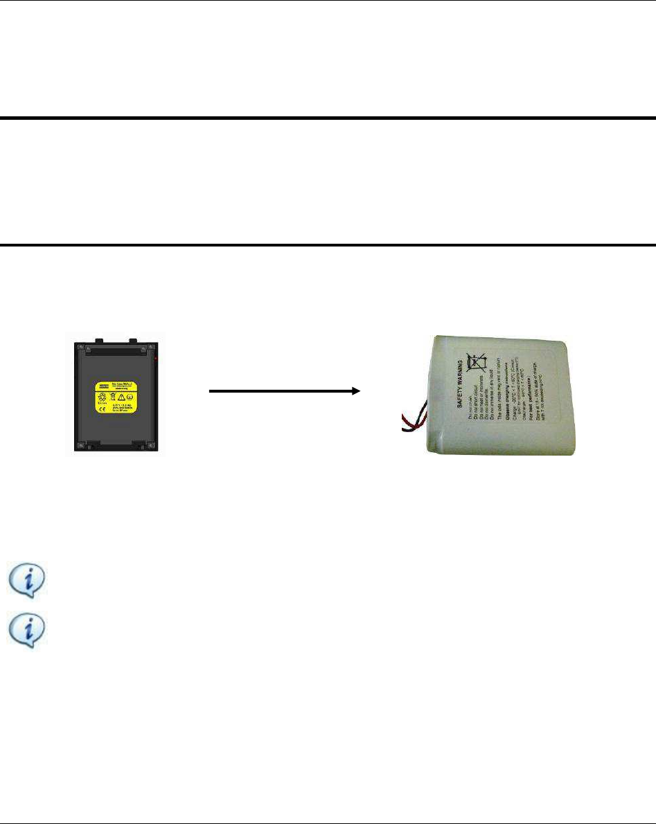
BATTERY PACK SPECIFICATION
P/N: 8059 0955 61
TYPE: Lithium-ion, 3.75V 6.8Ah
WEIGHT: 155g
The cells are installed inside the battery shell:
NOTE: Once removed, the wasted batteries must be dismissed according to local regulations.
NOTE: Battery

STa 6000 User Guide Introduction
9836 8243 01 Edition 3.1 13 (324)
1 INTRODUCTION
1.1 About this Document
This document is a User Guide for the STa 6000 and it is divided into the main following parts:
Part Name Description
Chapter 1 Introduction This chapter introduces this user guide and provides the
STa 6000 technical specifications.
Chapter 2 System Overview This chapter introduces the STa 6000 with its models and
accessories.
Chapter 3 User Interfaces This chapter provides an overview of the user interfaces
available on the STa 6000 (display, keyboard, ports, etc).
Chapter 4 Working with ToolsTalk
BLM
This chapter introduces the operations of the STa 6000
management software.
Chapter 5 Transducers This chapter describes which type of transducer can be
connected to the STa 6000.
Chapter 6 Getting Started with STa
6000
This chapter explains to the operator how to use the STa
6000 in the Quick Programming mode.
Chapter 7 Pset This chapter explains how to create, configure and
execute a test program.
Chapter 8 Tool Testing This chapter details how to set the parameters to test
click-wrenches, slip-wrenches, power and impulse tools.
Chapter 9 Joint Testing This chapter details how to set the parameters to test a
joint using the various residual torque strategies, and the
joint analysis function.
Chapter 10 Power Focus / PowerMACS
Calibration
This chapter explains how to calibrate the torque of the
tools/spindles of Power Focus and PowerMACS, using
the STa 6000 with a reference transducer.
Chapter 11 Identifier This chapter describes the use of barcode readings with
the STa 6000.

Introduction STa 6000 User Guide
14 (324) 9836 8243 01 Edition 3.1
Part Name Description
Chapter 12 Results Viewer This chapter explains how to retrieve the test results from
the instrument.
Chapter 13 Trace Viewer This chapter explains how to retrieve the test traces from
the instrument.
Chapter 14 Statistics This chapter shows the SPC and Cm-Cmk statistics
produced by the STa 6000 and ToolsTalk BLM.
Chapter 15 Offline Programming This chapter explains how to define tightening programs
and STa 6000 configuration offline, to transfer then the
file to one or more STa 6000.
Chapter 16 STa 6000 Settings This chapter explains how to setup the STa 6000 and its
accessories.
Chapter 17 Working with Torque
Supervisor
This chapter explains the use of the STa 6000 with
Torque Supervisor.
Chapter 18 Working with IRC-Connect This chapter explains the use of the STa 6000 with IRC-
Connect.
Chapter 19 Maintenance This chapter describes the required maintenance for the
STa 6000.
Chapter 20 Torque / Angle Coefficient
Calculation for MRTT-C
Extension
This chapter shows the operator how to calculate the
correction coefficients when an extension is used with
the MRTT-C.
Chapter 21 STa 6000 Factory Settings This chapter shows the STa 6000 factory settings.
Chapter 22 Appendix A EAP-TLS
security type
This chapter described how to configure the IRC-W
module for EAP-TLS security type.
Chapter 23 Troubleshooting Guide This chapter provides a guide to solve the most common
problems with the STa 6000.
Chapter 24 Abbreviations Table of abbreviations used in this user guide.
Chapter 25 Index Index used in this user guide.

STa 6000 User Guide Introduction
9836 8243 01 Edition 3.1 15 (324)
1.2 Reference Documents
The following is a list of important documents useful for a complete view of the product in all its
applications:
STa 6000 Safety Information (No. 9836 5229 01): Multilanguage safety instructions and declaration of
conformity
ToolsTalk BLM registration procedure: How to register the software on the Atlas Copco website
STa 6000 calibration procedure: Procedure to calibrate the STa 6000 (only for use of authorized
calibration centers)
Installation guides for STa 6000 modules: Detailed installation instructions, delivered with each part
IRTT-B, SRTT-B, MRTT-B and MRTT-C User Guides
IRC-Connect User Guide (No. 9836 6340 01)
Torque Supervisor User Guide (No. 9836 2866 01)
1.3 Specifications
TECHNICAL
Torque range: The torque range is defined by the transducer connected to the STa 6000.
Maximum accuracy error: ± 0.1 %.
Maximum linearity error: ± 0.015 %.
Angle measurement
Results memory capacity: 50000 test results
Traces memory capacity: 50000 traces (average duration: 30 s)
Pset memory capacity: 1000 Psets (1 for STa 6000 Basic)
Tools memory capacity: 1000 Tools (1 for STa 6000 Basic)
Number representation for torque values:
Nominal Torque (T) Measured torque shown on display
T < 5 M 1 three digits after decimal point
Measured torque < 1 four digits after decimal point
5 < T 50 M 10 two digits after decimal point
Measured torque < 10 three digits after decimal point
50 < T 500 M 100 one digits after decimal point
Measured torque < 100 two digits after decimal point

Introduction STa 6000 User Guide
16 (324) 9836 8243 01 Edition 3.1
Nominal Torque (T) Measured torque shown on display
500 < T 5000 M 1000 no digits after decimal point
Measured torque < 1000 one digits after decimal point
T > 5000 no digits after decimal point
NOTE: In the above table, the Unit of Measurement of the torque can be set according to the
following available options: N·m, kgf·m, kgf·cm, lbf·ft, lbf·in, ozf·ft, ozf·in, kp·m, dN·m , kN
Sampling frequency:
- Click-wrench test: 2 kHz
- Power tool test: 5 kHz
- Peak test: 1 kHz
- Pulse tool and ACTA pulse tool test: 10 kHz
Maximum number of identifier strings: 1000
Units of Measurement supported: N·m, kgf·m, kgf·cm, lbf·ft, lbf·in, ozf·ft, ozf·in, kp·m, dN·m , kN
EXTERNAL POWER SUPPLY
Input power: 100 ÷ 240 VAC, 50 ÷ 60 Hz
AC Power Consumption: 21 W maximum
Output: 6VDC, max 3.0A
BATTERY PACK
Battery power supply: 3.75 V, 6.8 Ah
Battery type: Lithium-ion (Li-ion)
Endurance: 8 hours in normal usage, 6 hours in continuous operation (1 test every 30 seconds)
Recharging max. 8 hours
BATTERY CHARGER
Input power: 100 ÷ 230 VAC
AC Power Consumption: 70 W maximum
Output: 4.2 VDC 13 W maximum
Overvoltage category: II
STa 6000 User Guide Introduction
9836 8243 01 Edition 3.1 17 (324)
SRTT-L
Torque measurement range: 0.1 ÷ 30 Nm
Torque static accuracy (from 20% to 100% of the transducer capacity): ± 0.25% of rated max.
transducer capacity
Overload capacity: 125% of rated max. transducer capacity
Temperature stability: 0.1% of capacity/10°C
Bridge resistance: 350 ohm
Operation humidity: 10-75% non-condensing
Operating temperature: 5 to 40°C
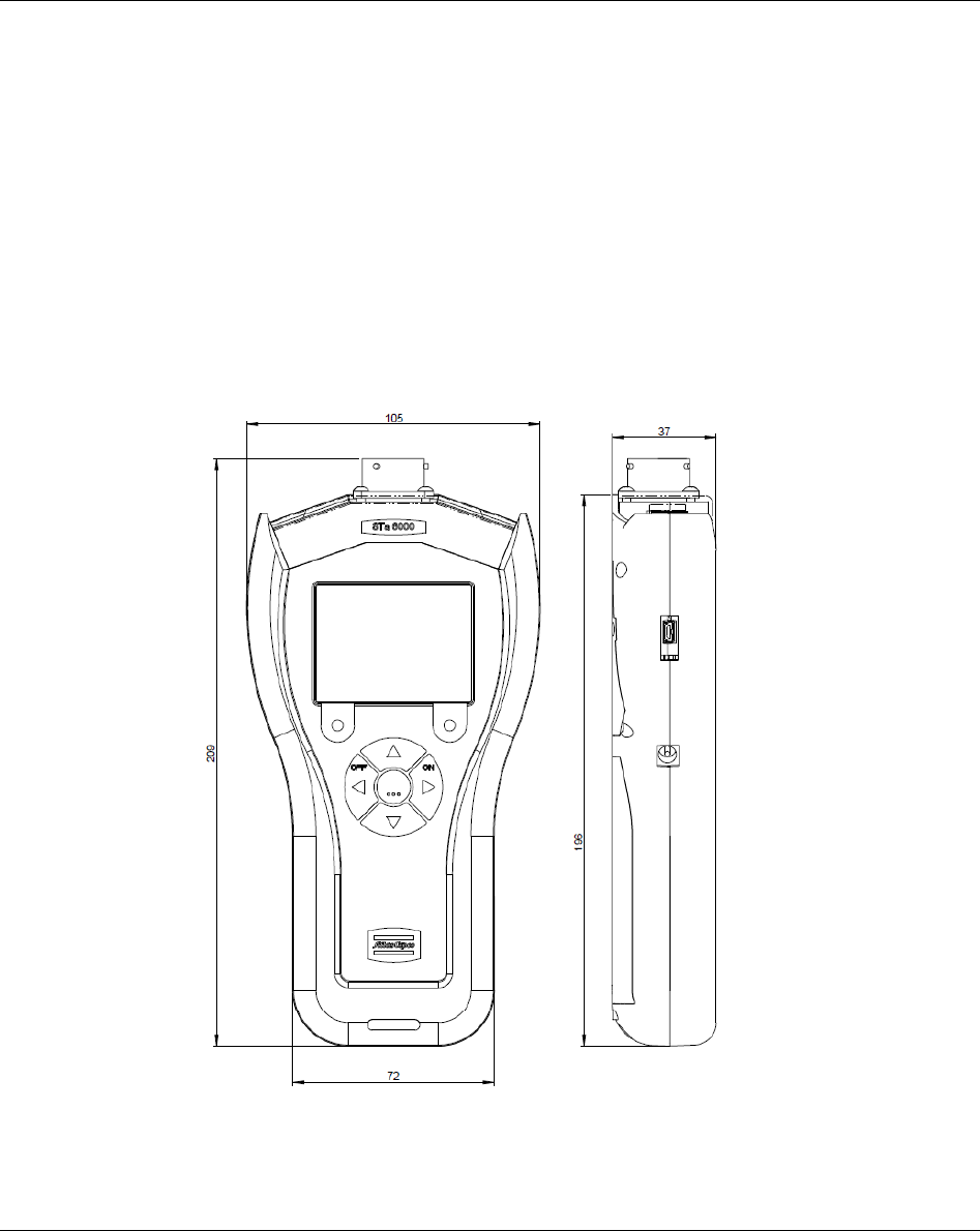
DIMENSIONS AND WEIGHT
Dimensions are in mm.
Max Weight (with battery): 500 g

Introduction STa 6000 User Guide
18 (324) 9836 8243 01 Edition 3.1
INTERFACES
MiniUSB 2.0 port
Transducer connector: 19 poles military connector for:
- IRTT-B and IRTT
- SRTT-B and SRTT
- MRTT-B and MRTT
- MRTT-C
- SRTT-L
- mV/V torque transducers (0.4 mV/V to 2.5 mV/V, bridge resistance 350 to 1000 Ohm)
Barcode reader module (optional):
- Visible laser diode 650 nm
- Output power: 1 mW maximum
- Scan rate: 104 ± 12 scans/second (bi-directional)
- Scan angle: 47° ± 3°
- Scan patterns: Linear
- Minimum Print contrast: Minimum 20% absolute dark/light reflectance measured at 650 nm
- Ambient light:
o Sunlight: 10000 ft candles (107640 Lux)
o Artificial: 450 ft candles (4484 Lux)
- EMI/RFI: FCC Part 15 Class B, EN 55024/CISPR 22, AS 3548, VCCI
- Laser Safety: IEC 60825 class 2
IRC-W dual band radio module (optional):
- Minimum IRC-W module firmware version: 2.14
- Type: 802.11a/b/g/n
- Frequencies:
CHANNEL CENTER FREQUENCY (MHz) EU USA Max. E.I.R.P. (mW)
1 2412 YES YES
0.9
2 2417 YES YES
3 2422 YES YES
4 2427 YES YES
5 2432 YES YES
6 2437 YES YES
0.79
7 2442 YES YES
8 2447 YES YES
9 2452 YES YES
10 2457 YES YES
STa 6000 User Guide Introduction
9836 8243 01 Edition 3.1 19 (324)
CHANNEL CENTER FREQUENCY (MHz) EU USA Max. E.I.R.P. (mW)
11 2462 YES YES
0.58
12 2467 YES N/A
13 2472 YES N/A
14 2484 N/A N/A
CHANNEL CENTER FREQUENCY (MHz) FCC U-NII
Band(s) EU USA Max. E.I.R.P.
(mW)
36 5180 U-NII-1 YES YES
0.41
40 5200 U-NII-1 YES YES
44 5220 U-NII-1 YES YES
48 5240 U-NII-1 YES YES
52 5260 U-NII-2A YES YES
56 5280 U-NII-2A YES YES 0.52
60 5300 U-NII-2A YES YES
64 5320 U-NII-2A YES YES 0.64
100 5500 U-NII-2C YES YES
2.11
104 5520 U-NII-2C YES YES
108 5540 U-NII-2C YES YES
112 5560 U-NII-2C YES YES
116 5580 U-NII-2C YES YES
1.67
132 5660 U-NII-2C YES YES
136 5680 U-NII-2C YES YES
140 5700 U-NII-2C YES YES
1.3
149 5745 U-NII-3 YES YES
153 5765 U-NII-3 YES YES
157 5785 U-NII-3 YES YES
161 5805 U-NII-3 YES YES
165 5825 U-NII-3 YES YES
Introduction STa 6000 User Guide
20 (324) 9836 8243 01 Edition 3.1
IRC-B radio module (optional):
- Bluetooth: v4.0 (Bluetooth low energy and Classic Bluetooth)
- Frequencies:
FREQUENCY RANGE (MHz) EU USA
2402 ÷ 2480 YES YES
CENTER FREQUENCY (MHz) Max. E.I.R.P. (mW)
2402 0.37
2441 0.39
2480 0.47
- Throughout: 1.3 Mbps (Classic Bluetooth)
- Microprocessor capacity: 72 MHz, ARM 32-bit Cortex M3 processor with 64kB RAM and
384kB flash
ENVIRONMENTAL
The following conditions must be observed during operation:
Internal Use only
Environmental Class: II
IP Index according to EN IEC 60529: IP40
Room Temperature: 5 to 40°C
Atmospheric humidity: 95%, non-condensing
Altitude: Up to 2000m
SYSTEM REQUIREMENTS
The following are the PC minimum requirements for installation of STa 6000 Management Software
(ToolsTalk BLM):
Processor: 400 MHz (800 MHz or above recommended)
Memory: 256 Mb or above
Hard disk space: 610 Mb (1 Gb or above recommended)
Display: 800 x 600, 256 colors (1024 x 768, High Color (16-bit) recommended)
Operating Systems: Windows XP Service Pack 2 (SP2), Windows 7, Windows 8.1, Windows 10
Internet Explorer 5.01 or later (required for installation of the .NET Framework)
Windows Installer 3.1

STa 6000 User Guide Introduction
9836 8243 01 Edition 3.1 21 (324)
Microsoft Excel 2007 or later (required to view the exported file with the tightening results)
NOTE: A system should meet these or the minimum requirements for the operating system,
whichever is higher.
CALIBRATION CERTIFICATE
STa 6000 is provided with an Atlas Copco BLM factory calibration certificate.
1.4 EC Declaration of Conformity
The STa 6000 is in conformity with the requirements of the council Directives on 06/22/1998 on the
approximation of the laws of the Member States relating:
2004/108/EC EMC Directive Electromagnetic Compatibility
2011/65/EC ROHS Directive Risk Of Hazardous Substances
1999/05/EC R&TTE Directive Radio and Telecommunications Terminal Equipment
Safety complies with the following regulations:
STa 6000
EN 61010-1:2010 Safety requirements for electrical equipment for
measurement, control and laboratory use. General
requirements
Battery charger
IEC 60950-1:2005 + A1:2009 + A2:2013 Safety of electronic equipment within the field of
audio/video, information technology and
communication technology. General requirements
The STa 6000 is marked with the following symbol:

Introduction STa 6000 User Guide
22 (324) 9836 8243 01 Edition 3.1
The STa 6000 may be operated in the following countries:
Country ISO 3166
2 letter code
Country ISO 3166
2 letter code
Country ISO 3166
2 letter code
Country ISO 3166
2 letter code
Austria AT Germany DE Malta MT United
Kingdom
GB
Belgium BE Greece GR Netherlands NL Iceland IS
Cyprus CY Hungary HU Poland PL Liechtenstein LI
Czech
Republic
CZ Ireland IE Portugal PT Norway NO
Denmark DK Italy IT Slovakia SK Switzerland CH
Estonia EE Latvia LV Slovenia SI Bulgaria BG
Finland FI Lithuania LT Spain ES Romania RO
France FR Luxembourg LU Sweden SE Turkey TR
1.5 FCC Rules
The STa 6000 complies with part 15 of the FCC Rules.
STATEMENT FCC 15.19
Operation is subject to the following two conditions:
(1)
The STa 6000 may not cause harmful interference.
(2)
The STa 6000 MUST accept any interference received, including interference that may cause
undesired operation.
STATEMENT FCC 15.21
Changes or modifications made to this equipment not expressly approved by the party responsible for
The FCC ID of the STa 6000 is as follows:
FCC ID: 2AEWDSTA6K
This device contains:
- FCC ID: PVH0941
- FCC ID: PVH0946
STa 6000 User Guide System Overview
9836 8243 01 Edition 3.1 23 (324)
2 SYSTEM OVERVIEW
The STa 6000 is a modular instrument designed for optimal operations in:
Tool testing: The STa 6000 (QC and AA versions) offers a set of tests for evaluating click-wrenches,
slip-wrenches, power tools and pulse tools, measuring the torque/angle values and producing results
with statistical parameters. This makes possible to keep the quality of the tightening operations on a
production line under control. The test results can be retrieved by the STa 6000 management software
(ToolsTalk BLM), or exported into Microsoft Excel.
Quality tests: The STa 6000 (QC and AA versions) offers a set of strategies to perform residual
torque tests and joint analysis. With this instrument it is possible to keep under control the quality of
the tightenings on the assembly line and to perform analysis of the joints characteristics.
Tightening operations: Not available in this software version.
NOTE: The STa 6000 can also work in conjunction with Torque Supervisor, which sends the
route of tests and retrieve the results.
STa 6000
Transducers (cable or wireless)
PC
ToolsTalk BLM
Barcode reader
IRC
-
W

System Overview STa 6000 User Guide
24 (324) 9836 8243 01 Edition 3.1
2.1 STa 6000 Versions
This chapter provides an overview of the STa 6000 versions. The STa 6000 version is defined by the
Rapid Backup Unit (RBU) installed:
Basic (no RBU) QC AA RBU
HARDWARE CAPABILITY
Number of Channel
1
1
1
Torque
Yes
Yes
Yes
Angle (Encoder or Gyroscope)
Yes
Yes
Yes
MRTT
-
C connection for joint checks
Yes
Yes
Yes
Size in mm
110x200x45
110x200x45
110x200x45
Weight
[grams]
500
500
5
00
Color Display
Yes
Yes
Yes
Keyboard
Yes
Yes
Yes
Result Storage
50000
50000
50000
Traces Storage
50000
50000
50000
RBU
Rapid Backup Unit
No
Yes
Yes
Direct power Supply (slow charger 6H)
Yes
Yes
Yes
RJ45 (Ethernet)
Yes
Yes
Yes
USB
Yes
Yes
Yes
No
n Atlas Copco analog transducer connection
Yes
Yes
Yes
SOFTWARE CAPABILITY - ONBOARD
Languages
Yes
Yes
Yes
Multi
-
units
Yes
Yes
Yes
Pset 1 (not saved) 1000 1000
Batch Count Yes Yes Yes
CW/CCW Yes Yes Yes
Database - Tool No 1000 1000
Quick Programming Yes Yes Yes
Power Focus and PowerMACS calibration No Yes Yes
Traces on display No Yes Yes
Advanced analysis graphs on display No No Yes
Custom measurement screen No Yes Yes
Wi-Fi print Yes (with IRC-W module) Yes (with IRC-W module) Yes (with IRC-W module)
Ethernet print Yes Yes Yes
SOFTWARE FUNCTIONALTIES - ONBOARD
Tool Check
Wrench testing Yes Yes Yes
Power tool testing Yes Yes Yes
Pulse Tool testing Yes Yes Yes
Min, Max, Med, Sigma statistics Yes Yes Yes
Cm/Cmk No Yes Yes
STa 6000 User Guide System Overview
9836 8243 01 Edition 3.1 25 (324)
SPC
No
Yes
Yes
Joint Check
Yield Point
Yes
Yes
Yes
Residual Torque/Time
Yes
Yes
Yes
Residual Torque/Angle
Yes
Yes
Yes
Residual Torque/Peak
Yes
Yes
Yes
Loose and Tight
Yes
Yes
Yes
SOFTWARE CAPABILITY - CONNECTIVITY
ToolsTalk BLM to view/export results and traces vi
a
Wi-Fi (with IRC-W), USB/RJ45 Yes Yes Yes
ToolsTalk BLM to program test strategies via Wi
-
Fi
(with IRC-W), USB/RJ45 No Yes Yes
Torque Supervisor via Wi
-
Fi (with IRC
-
W),
USB/RJ45 No Yes Yes
API via Wi
-
Fi (with IRC
-
W), USB/RJ45
No
Yes (with API RBU)
Yes
(with API RBU)
2.1.1 Basic
The STa 6000 without a RBU installed works as STa Basic. It provides the Quick
Programming mode with tools testing menu (Click-wrench, Power Tool, Peak Wrench and
Pulse Tool). One Pset and one Tool can be defined directly on the STa 6000 menu (not by
ToolsTalk BLM), but they are not saved in the STa 6000 Basic memory.
The results are stored in the STa 6000 memory and can be retrieved (and possibly printed)
by the management software (ToolsTalk BLM), but they cannot be transferred to any remote
devices; they can be exported to Excel.
2.1.2 QC (Quality Control)
The STa 6000 QC provides tool test and quality test functions. This
includes tests of tightening tools (Click-wrench, Power Tool, Peak
Wrench and Pulse Tool), and tests of joints to evaluate the residual
torque. Free test function is also available.
It provides Pset definition, transducers database, real time statistics
on the display. This instrument provides also Power Focus /
PowerMACS calibration function.
The results are stored in the STa 6000 memory and can be retrieved (and possibly printed) by the
management software (ToolsTalk BLM), or exported to Excel.
This version can also work in conjunction with Torque Supervisor.
NOTEWorking with Torque Supervisor
RBU - QC
System Overview STa 6000 User Guide
26 (324) 9836 8243 01 Edition 3.1
2.1.3 AA (Advanced Analysis)
The STa 6000 AA provides the same function of the QC version,
plus the Cm-Cmk histogram and SPC X/R Charts available on the
STa 6000 display.
2.2 STa 6000 Typical Applications Scenario
This chapter provides a quick overview of the main applications of the STa 6000.
2.2.1 Stand-alone STa 6000
The STa 6000 can work as a stand-alone instrument, programmed by its management software (ToolsTalk
BLM), which can display the traces, retrieve tightening results, to be exported in a Microsoft Excel file,
and possibly printed, if required.
NOTEWorking with ToolsTalk BLMer details.
RBU - AA
STa 6000 User Guide System Overview
9836 8243 01 Edition 3.1 27 (324)
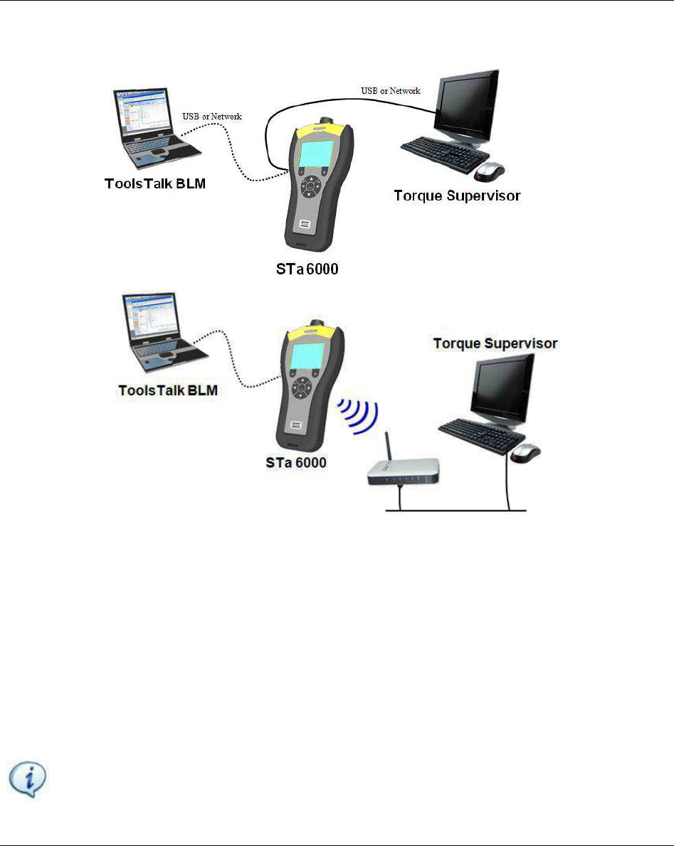
2.2.2 STa 6000 connected to Torque Supervisor
The STa 6000 QC and AA versions can work in conjunction with Torque Supervisor. The communication
is performed trough USB, network cable or IRC-W.
In this application Torque Supervisor generates and sends to the STa 6000 the list of tests to be done (the
!"s, Torque Supervisor downloads the results and stores them in the
tool statistics.
The ToolsTalk BLM is necessary only for settings of the STa 6000; for basic operation of the STa 6000
with Torque Supervisor, it can be not necessary. In the typical application the Torque Supervisor is
installed in one or more dedicated PC, and ToolsTalk BLM on another one. However, they can run on the
same PC.
NOTE: Refer to the Working with Torque Supervisor
System Overview STa 6000 User Guide
28 (324) 9836 8243 01 Edition 3.1
2.3 Presentation
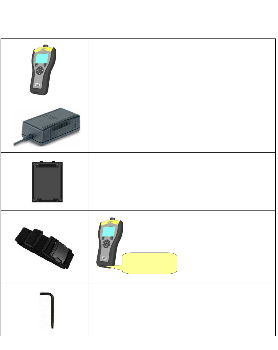
The STa 6000 is modular. The following items are delivered with the STa 6000 package:
STa 6000 Controller
(STa 6000 PLUS 1)
The main module of the STa 6000, which contains all the
hardware and firmware.
Controller is provided without battery.
External Power Supply (P/N 4612 0300 21) (delivered with the STa
6000 package)
Power supply. If battery and battery charger are used, the external
power supply is not strictly necessary.
Battery cover (delivered with the STa 6000 package)
This battery cover must be installed in the STa 6000 when the
battery is not used (STa 6000 powered by the external power
supply).
Nylon Strap (delivered with the STa 6000 package)
The nylon strap can be attached to the STa 6000 for
easy portability. It is allowed to tie the Nylon Strap on
the own belt.
Torx wrench (delivered with the STa 6000 package)
This wrench is used to remove the STa 6000 back cover to install
the RBU or IRC-W module or Barcode module.
Attach here the
nylon strap
STa 6000 User Guide System Overview
9836 8243 01 Edition 3.1 29 (324)
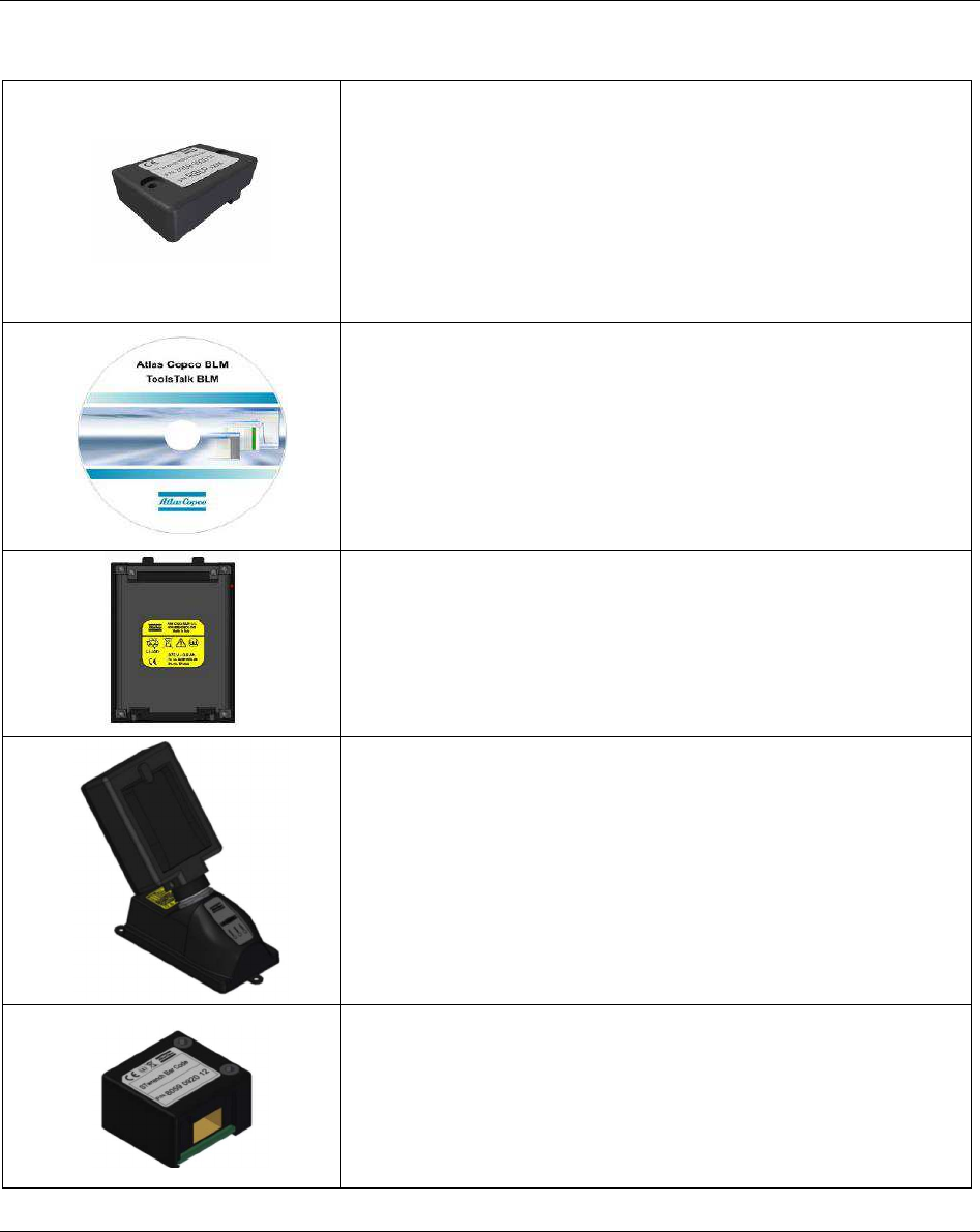
The following are additional modules for the STa 6000:
STa 6000 RBU (Rapid Backup Unit)
(RBU QC )
(RBU AA P/N 8059 0956 63)
Module to be installed in the STa 6000. It defines the STa 6000
type and stores test programs, tools and transducers archives,
STa 6000 configuration.
If not used, the STa 6000 works as STa 6000 Basic.
ToolsTalk BLM (P/N 8059 0981 10)
The STa 6000 management software. It features STa 6000
programming, STa 6000 configuration, retrieving results and
traces from the STa 6000.
STa 6000 Battery (P/N 8059 0955 61)
Power supply.
NOTE: Battery is optional. The STa 6000 can be powered also by
the external power supply.
Battery charger adapter (P/N 8059 0955 75)
The STa 6000 battery can be recharged when installed in the
unit by the external power supply, or on the specific battery
charger.
The battery charger is the same of the STwrench; it requires the
adapter to recharge the STa 6000 battery.
QAT Barcode module (P/N 8059 0920 12)
Module for scanning barcode labels on assembly components
for easy traceability.
It cannot be installed on the STa 6000 Basic.
System Overview STa 6000 User Guide
30 (324) 9836 8243 01 Edition 3.1
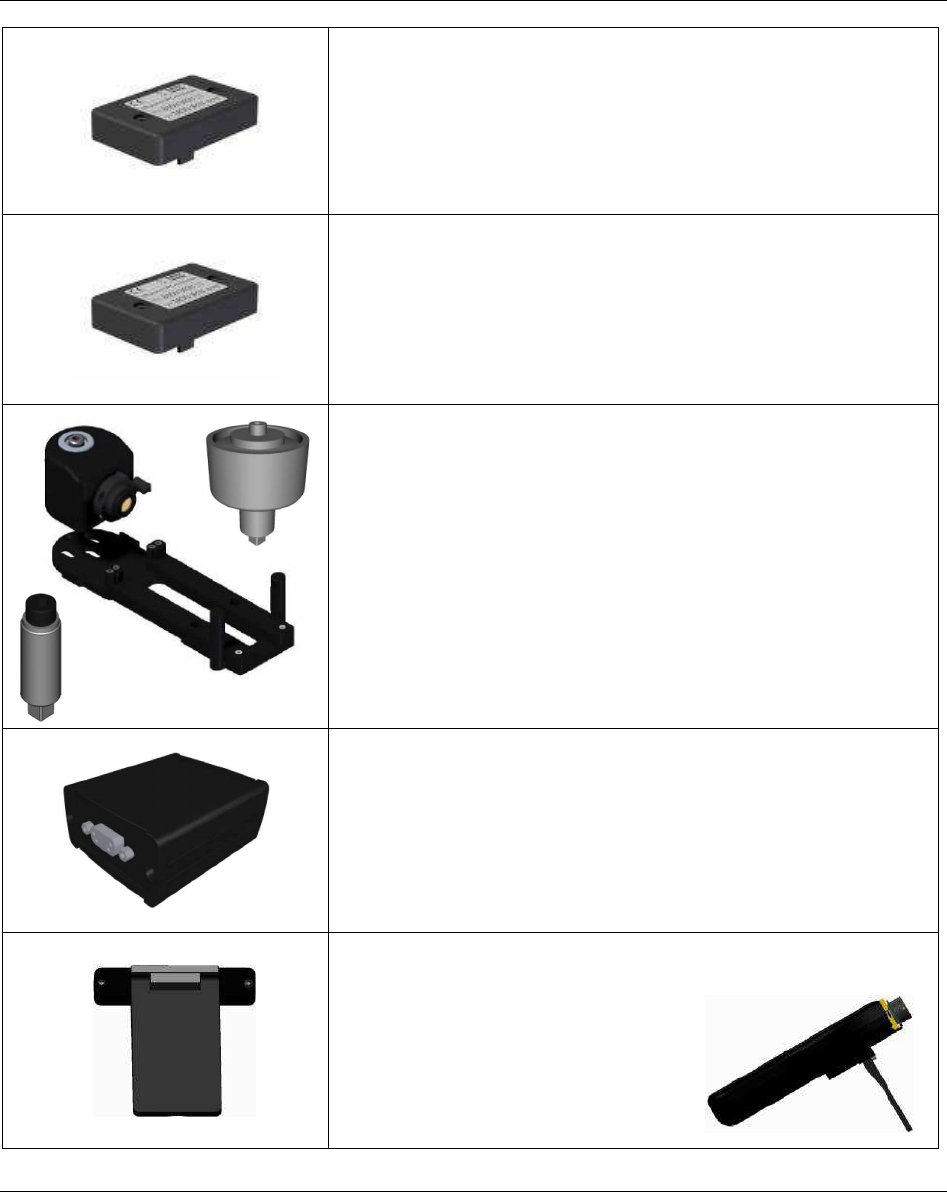
QAT IRC-B radio module (P/N 8059 0920 10)
Radio module for interfacing the STa 6000 with printer, Torque
Supervisor and ToolsTalk BLM.
It is possible to install one or two radio modules in the STa
6000.
QAT IRC-W dual band radio module (P/N 8059 0920 15)
Radio module for interfacing the STa 6000 with printer, Torque
Supervisor and ToolsTalk BLM.
It is possible to install one or two radio modules in the STa
6000.
SRTT-L main plate (P/N 8059 0955 85)
Torque transducer to be installed on the STa 6000 to create a
single unit with the transducer and the measurement system.
Mechanical joint simulators are also available to test power an
impulse tools on the SRTT-L.
USB / Serial Adapter (P/N 8059 0956 74)
This box is used to connect the STa 6000 to the Power Focus and
PowerMACS for calibration.
STa 6000 Stand (P/N 8059 0956 73)
This stand MUST be installed on
the back of the STa 6000. It is not
allowed to insert the STa 6000
Stand into the own belt. It may get
an easy reading once it is leaned on
a desk.
STa 6000 User Guide System Overview
9836 8243 01 Edition 3.1 31 (324)
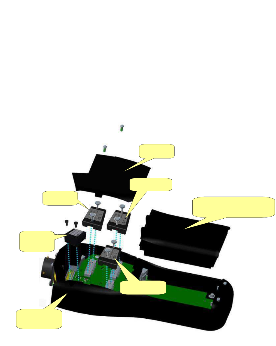
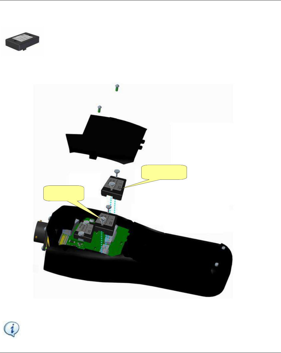
2.3.1 STa 6000 assembly
The STa 6000 is delivered in separated packages for each module; in order to start working with the
instrument, put all the pieces together:
1. Remove the cover from the controller.
2. If purchased, insert the RBU and IRC-W / IRC-B radio module(s) inside the controller. Tighten the
screws (to the torque applied by the fingers. Do not use pliers).
3. If purchased, insert the QAT Barcode Reader module and tighten the two mounting screws.
4. Mount the cover (tighten the two screws).
5. Insert battery, or connect the external power supply.
Battery, or battery cover if
battery not purchased
Cover
RBU
STa 6000
controller
Barcode
reader
Radio 1
Radio 2
System Overview STa 6000 User Guide
32 (324) 9836 8243 01 Edition 3.1
The STa 6000 is ready for the use:
NOTE: Once the STa 6000 is assembled with the IRC-W / IRC-B radio module(s), it is not
recommended to work by placing it either close to the head or close to the reproductive system.
The next paragraphs describe all the STa 6000 modules and user interfaces in detail.
NOTE: To start working with the STa 6000 immediately, Getting Started
with STa6000
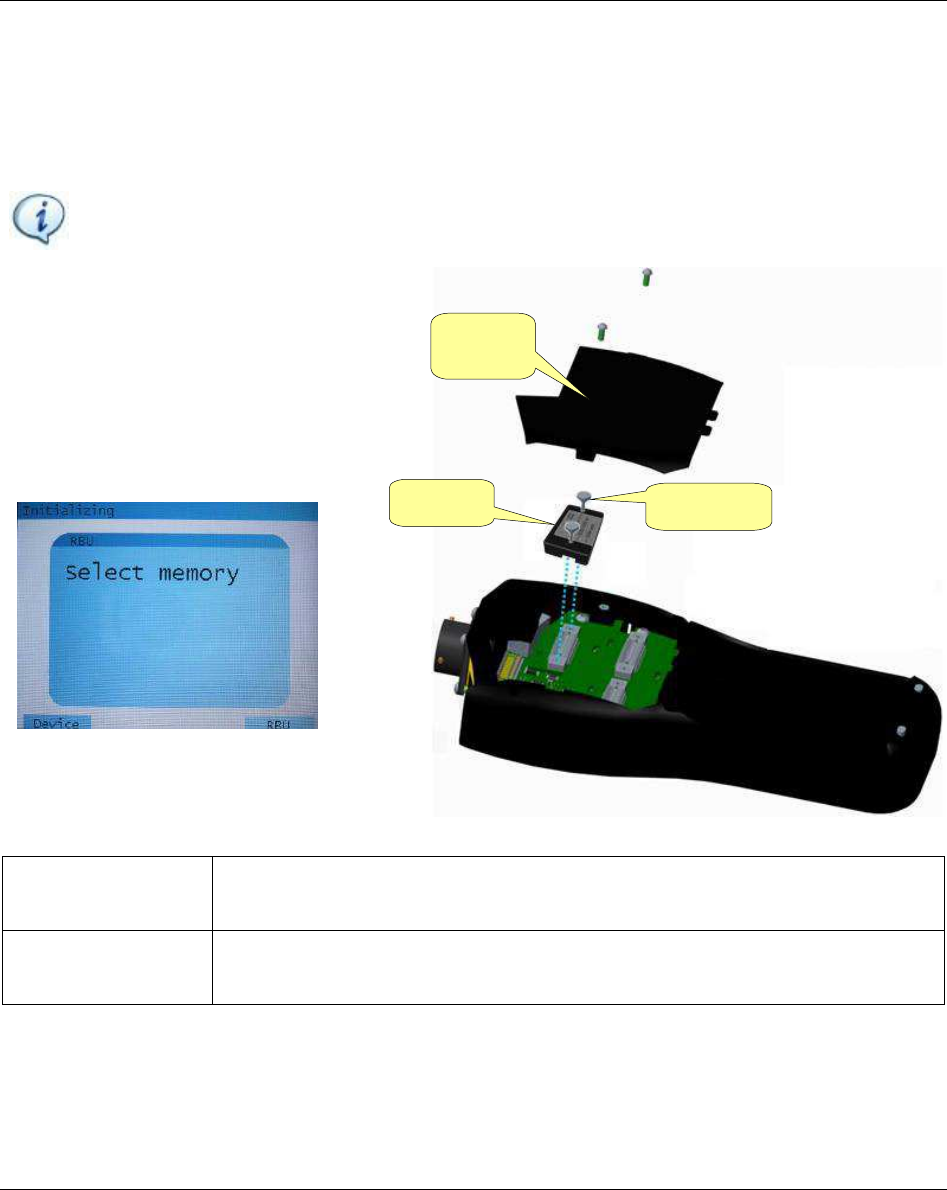
2.3.2 RBU
RBU (Rapid Backup Unit) is a memory chip which defines which functions are
activated and provides backup for the test programs.
It stores also the specific settings of the own STa 6000 (STa6000
Factory Settingsthe default configuration); by installing the RBU in another STa
6000 it is possible to get an exact copy of the original one (except for test results, stored
in the STa 6000 memory and not in the RBU).
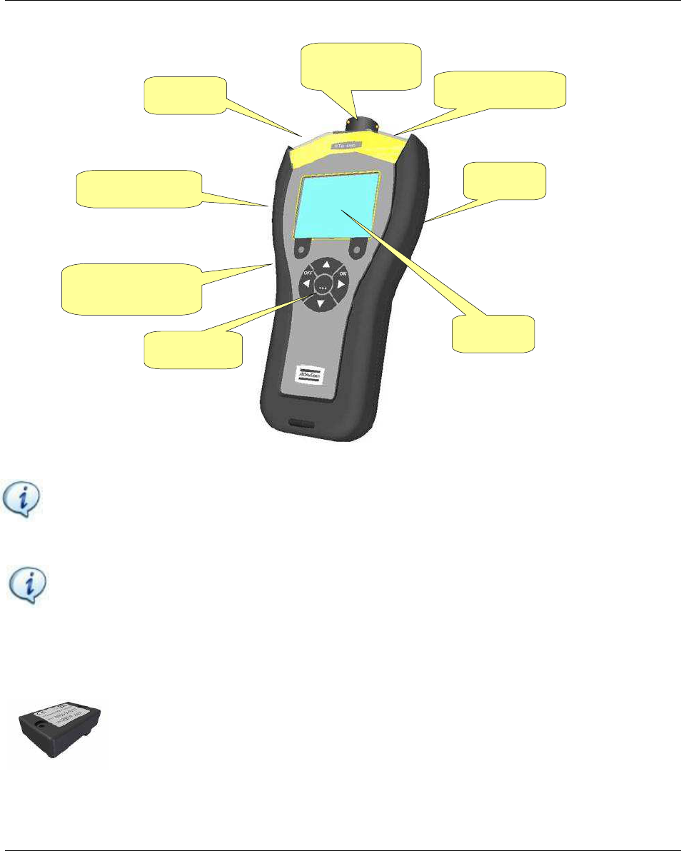
Display
Buzzer
Barcode reader
Keyboard
External power
supply connector
Mini USB port
Network
Connector for
transducers
STa 6000 User Guide System Overview
9836 8243 01 Edition 3.1 33 (324)
The following types of RBU are available:
RBU QC: Enables the strategies to evaluate the residual torque and to execute the joint analysis.
RBU AA: Same of RBU QC plus histogram and X/R charts on the STa 6000 display.
If the RBU is not installed, the STa 6000 works as STa 6000 Basic.
NOTE: RBUs of the STanalyser can be converted into RBU for STa 6000; in that case, once
installed on the STa 6000, they cannot be used any longer in the STanalyser.
To insert the RBU in the STa 6000, turn
off the STa 6000, remove the back cover,
insert the RBU module, and tighten the
two nuts by hands (do not use pliers).
The first time of RBU usage, the
following message is shown:
Device The data are loaded from the STa 6000 memory; all the data present in the RBU
are overwritten.
RBU The data (STa 6000 settings and all the test programs) are loaded from the RBU;
all the data stored in the STa 6000 memory are overwritten.
RBU
Screws
Back
cover
System Overview STa 6000 User Guide
34 (324) 9836 8243 01 Edition 3.1
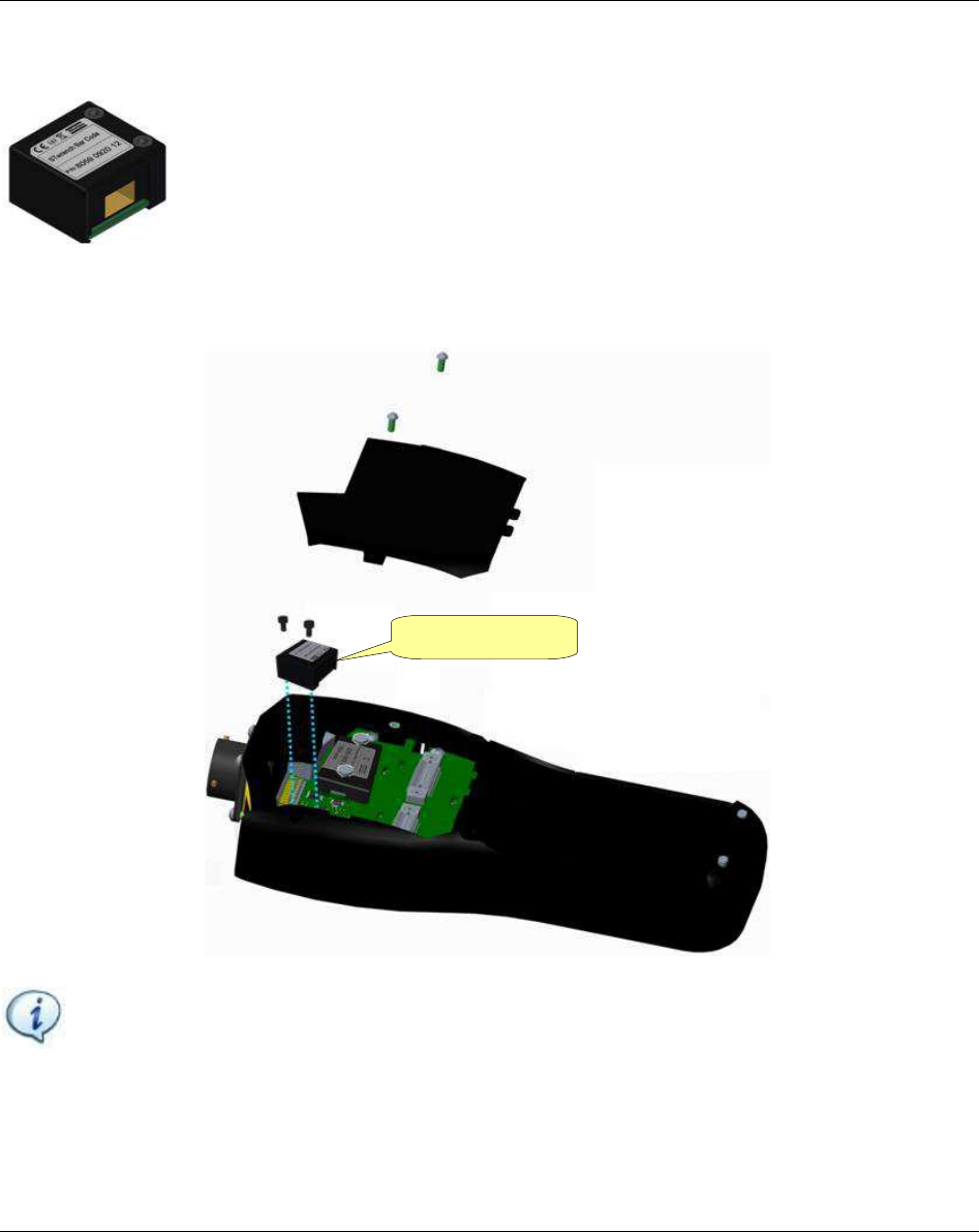
2.3.3 QAT Barcode reader
The QAT Barcode reader is a module to be installed into the STa 6000 to permit
scanning of barcodes.
An identifier, or barcode string, may be used to select the tightening program to be
executed, identify motor vehicles (VIN) and other work pieces, variants and
operators. The tightening result can then be saved together with this information.
To install the barcode reader module, turn off the STa 6000, remove the cover (by removing the two
screws) and insert the module (tighten the two screws):
NOTEIdentifier##
QAT Barcode
STa 6000 User Guide System Overview
9836 8243 01 Edition 3.1 35 (324)
2.3.4 IRC-W / IRC-B radio modules
The IRC-W Dual Band radio module / IRC-B radio module is used to interface the STa
6000 with the Printer, Torque Supervisor and ToolsTalk BLM.
It is possible to install one or two modules.
To install the IRC-W / IRC-B module, turn off the STa 6000, remove the cover and insert the IRC-W /
IRC-B module (tighten the two screws with the fingers).
After having installed the module(s) the radio module parameters must be set trough ToolsTalk BLM.
NOTE: Talking about Torque Supervisor$ Working with Torque
Supervisor
Radio 2
Radio 1
System Overview STa 6000 User Guide
36 (324) 9836 8243 01 Edition 3.1
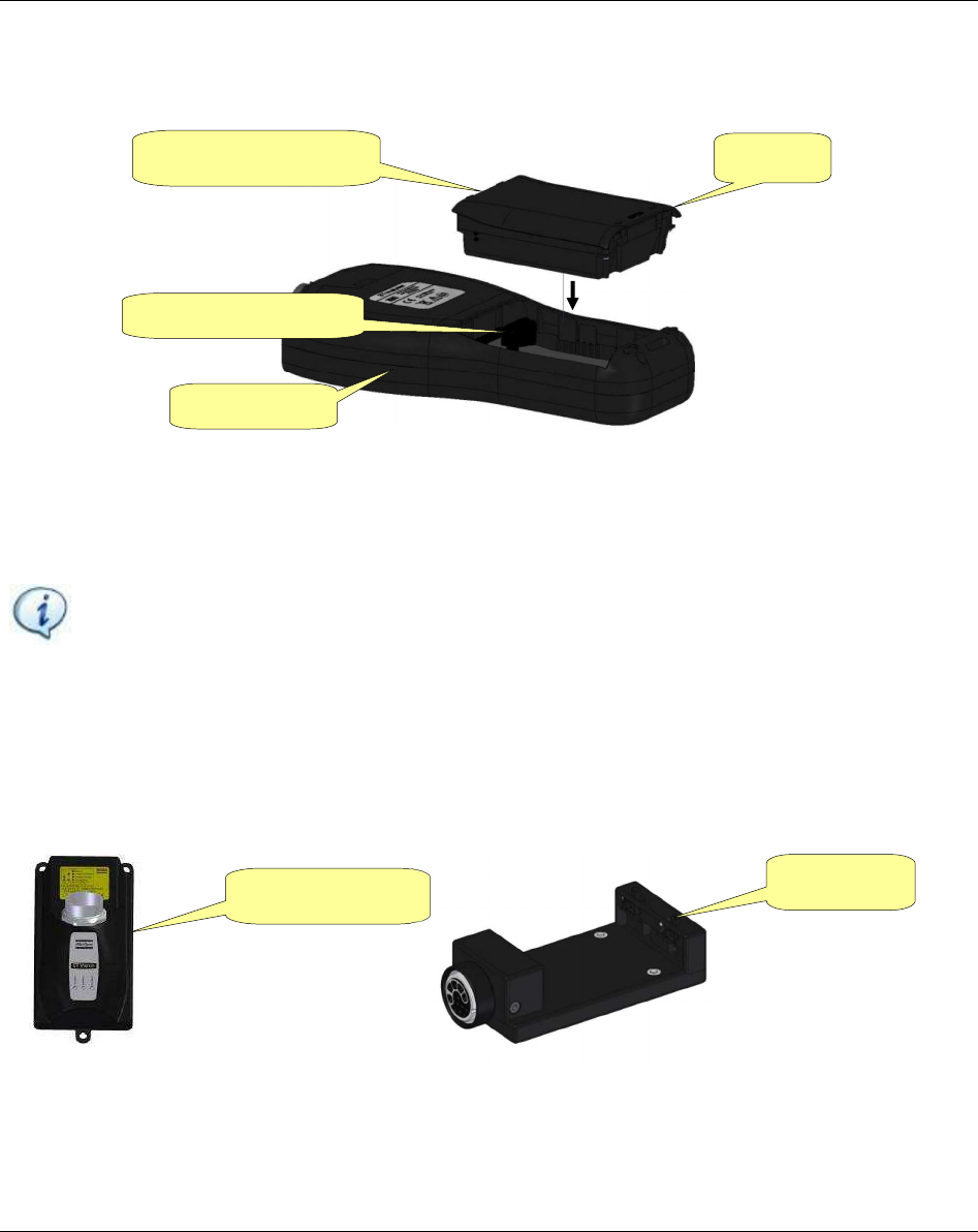
2.3.5 Battery
STa 6000 can operate powered by its battery pack or by the external power supply.
When the battery is not used, install the original cover supplied with the STa 6000.
To install the battery, turn off the STa 6000, remove the cover and then install the battery.
To replace a battery, switch off the STa 6000, remove the battery and install the new one.
NOTE: Refer to the Maintenance for important notes about how to keep battery in
a good working order.
2.3.5.1 Battery Charger
The battery can be charged either when installed in the STa 6000 (by the external power supply) or with
the specific battery charger. The battery charger is the same used for the STwrench. The specific adapter
to connect the STa 6000 battery is required.
Battery charger Adapter
Controller
Battery
1. Remove the cover
2. Insert this side first
STa 6000 User Guide System Overview
9836 8243 01 Edition 3.1 37 (324)
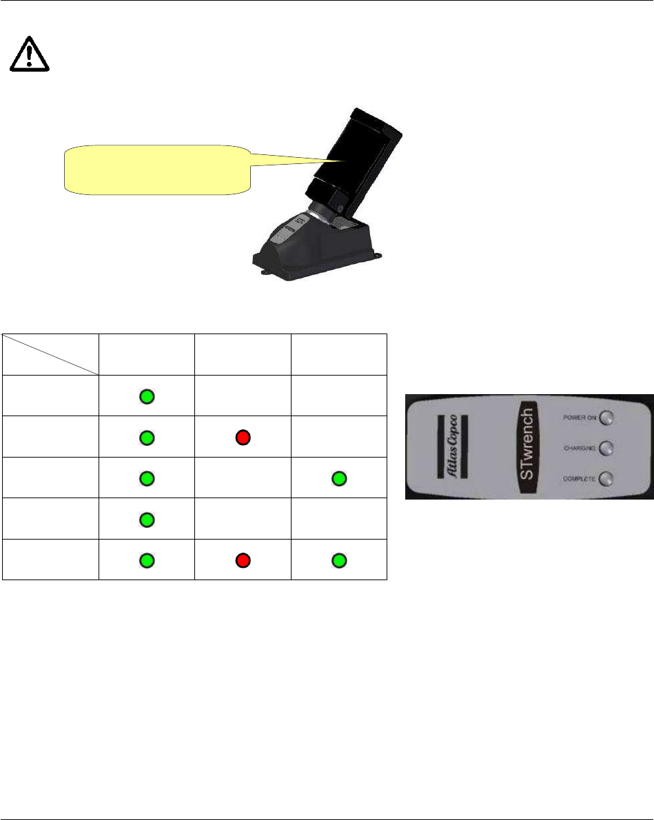
WARNING: The Battery Charger must be installed close to the AC Power (220 V) in order to
be easily managed by the user in case of malfunction.
Simply connect the input AC power cable to the battery charger and plug in the battery in the
adapter.
The three LEDs on the battery charger indicate the battery charge status:
In case of Over temperature, disconnect the battery from the battery charger, disconnect charger from AC
power, wait few minutes, reconnect the battery charger to AC power and the battery to the charger, and
check if the problem gets solved.
In case of Error, disconnect and then reconnect the battery to the battery charger and check if the problem
gets solved.
LED
Status POWER ON CHARGING COMPLETE
Power on
Charging in
progress
Charging
complete
Over
temperature Blinking
Error
Insert STa 6000 battery
in the adapter
System Overview STa 6000 User Guide
38 (324) 9836 8243 01 Edition 3.1
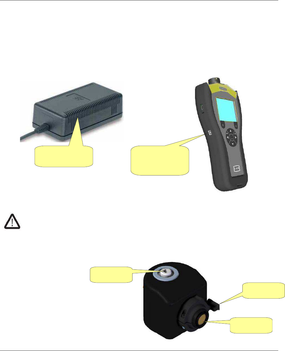
2.3.6 External power supply
The external power supply provides power to the instrument, and it also charges the battery when the
battery is installed in the STa 6000. The battery is charged even if the STa 6000 is switched off.
The battery icon on the STa 6000 shows the recharging process only when the STa 6000 is switched on.
Connect the external power supply to AC power 100 ÷ 230 VAC 50/60 Hz, and plug the connector into
the STa 6000.
WARNING: Use only the power supply ordered from Atlas Copco. Warranty does not cover
damages to the STa 6000 caused by the use of a different external power supply.
2.3.7 SRTT-L
The SRTT-L is a torque
transducer to be installed on the
STa 6000 to create a single unit
with the transducer and the
measurement system.
External power
supply
Connector for
external power
supply
Transducer
Connector
Lever
STa 6000 User Guide System Overview
9836 8243 01 Edition 3.1 39 (324)
The following models are available:
Code Description Capacity
8059 0955 86 SRTT-L 1 Nm 1 Nm
8059 0955 87 SRTT-L 4 Nm 4 Nm
8059 0955 88 SRTT-L 12 Nm 12 Nm
8059 0955 89 SRTT-L 30 Nm 30 Nm
8059 0955 85 SRTT-L main plate -
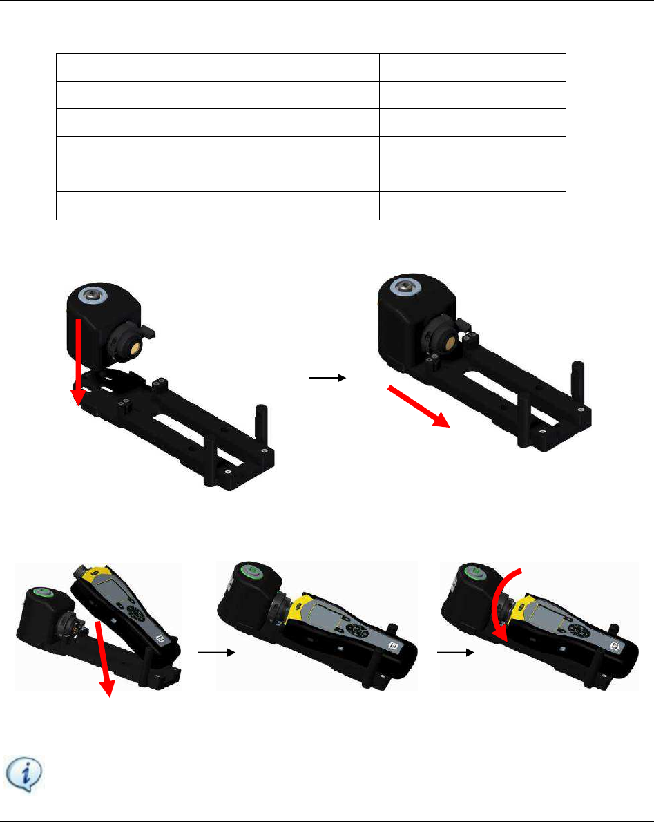
To use the SRTT-L, install first the transducer on the main plate:
Then, insert and slide the STa 6000 on the main plate, and finally rotate the SRTT-L lever to connect the
SRTT-L to the STa 6000:
There is no need of any setup. Simply switch on the STa 6000 and the SRTT-L is ready to use.
NOTE: The barcode reader feature is not available when the STa6000 is connected with the
SRTT-L.
System Overview STa 6000 User Guide
40 (324) 9836 8243 01 Edition 3.1
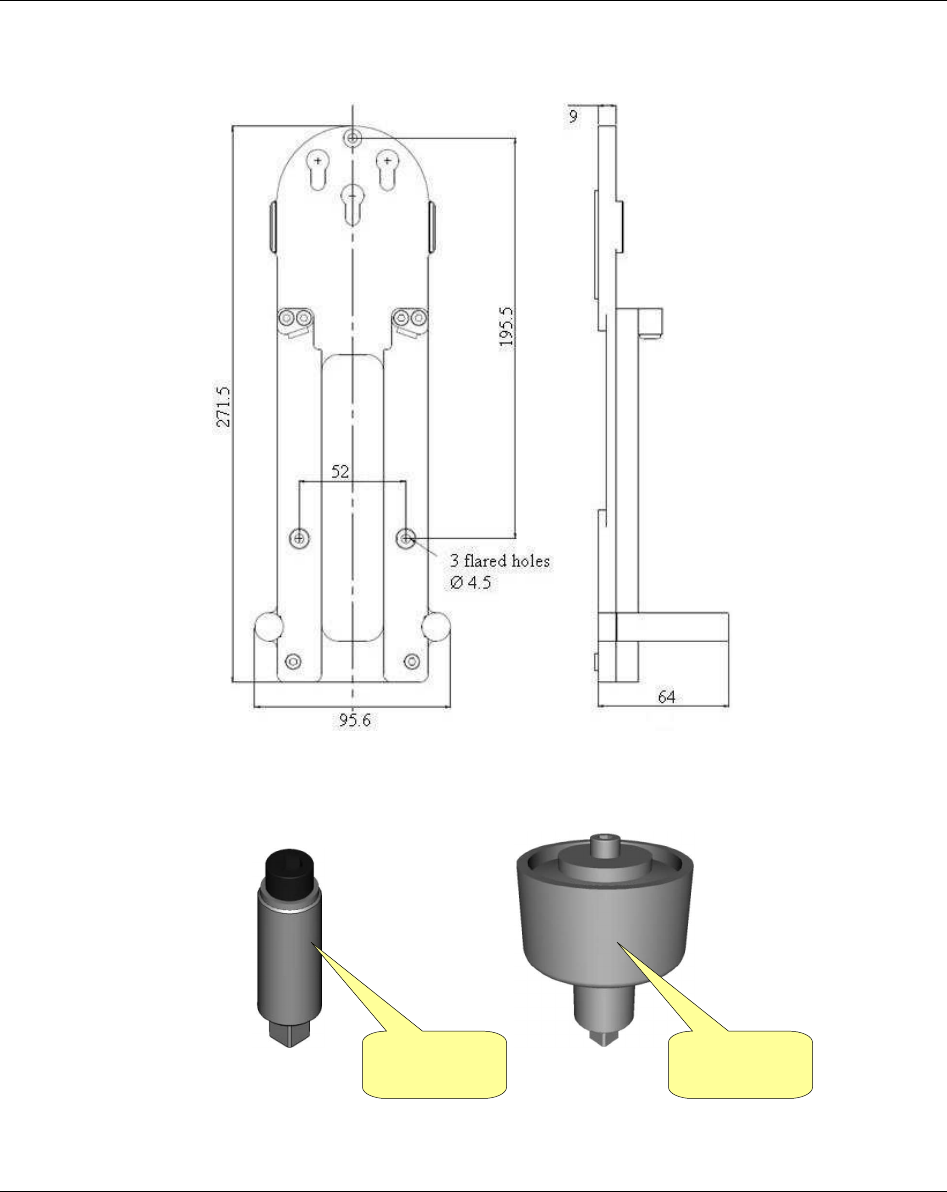
The plate can be attached to a table; refer to the following mechanical drawing for dimensions
(dimensions are in millimeters):
A series of mechanical joint simulators are available to test power and impulse tools on the SRTT-L:
Soft joint
simulation
Hard joint
simulation

STa 6000 User Guide System Overview
9836 8243 01 Edition 3.1 41 (324)
The following models are available:
Code Description Drive To be used on
4145098480 Test Joint M4 Soft 1Nm M4 SRTT-L 1 Nm
4145098483 Test Joint M4 Hard 1Nm M4 SRTT-L 1 Nm
4145098482 Test Joint M6 Soft 4Nm M6 SRTT-L 4 Nm
4145098485 Test Joint M6 Hard 4Nm M6 SRTT-L 4 Nm
4145098580 Test Joint M6 Soft 12Nm M6 SRTT-L 12 Nm
4145098582 Test Joint M6 Hard 12Nm M6 SRTT-L 12 Nm
4145098581 Test Joint M8 Soft 12Nm M8 SRTT-L 12 Nm
4145098583 Test Joint M8 Hard 12Nm M8 SRTT-L 12 Nm
4145098680 Test Joint M8 Soft 30Nm M8 SRTT-L 30 Nm
4145098682 Test Joint M8 Hard 30Nm M8 SRTT-L 30 Nm
4145098681 Test Joint M10 Soft 30Nm M10 SRTT-L 30 Nm
4145098683 Test Joint M10 Hard 30Nm M10 SRTT-L 30 Nm