Atoms Labs ADRC45HD IP Camera User Manual
Atoms Labs LLC IP Camera Users Manual
UserManual.wiki
>
Atoms Labs
>
ADRC45HD User Manual
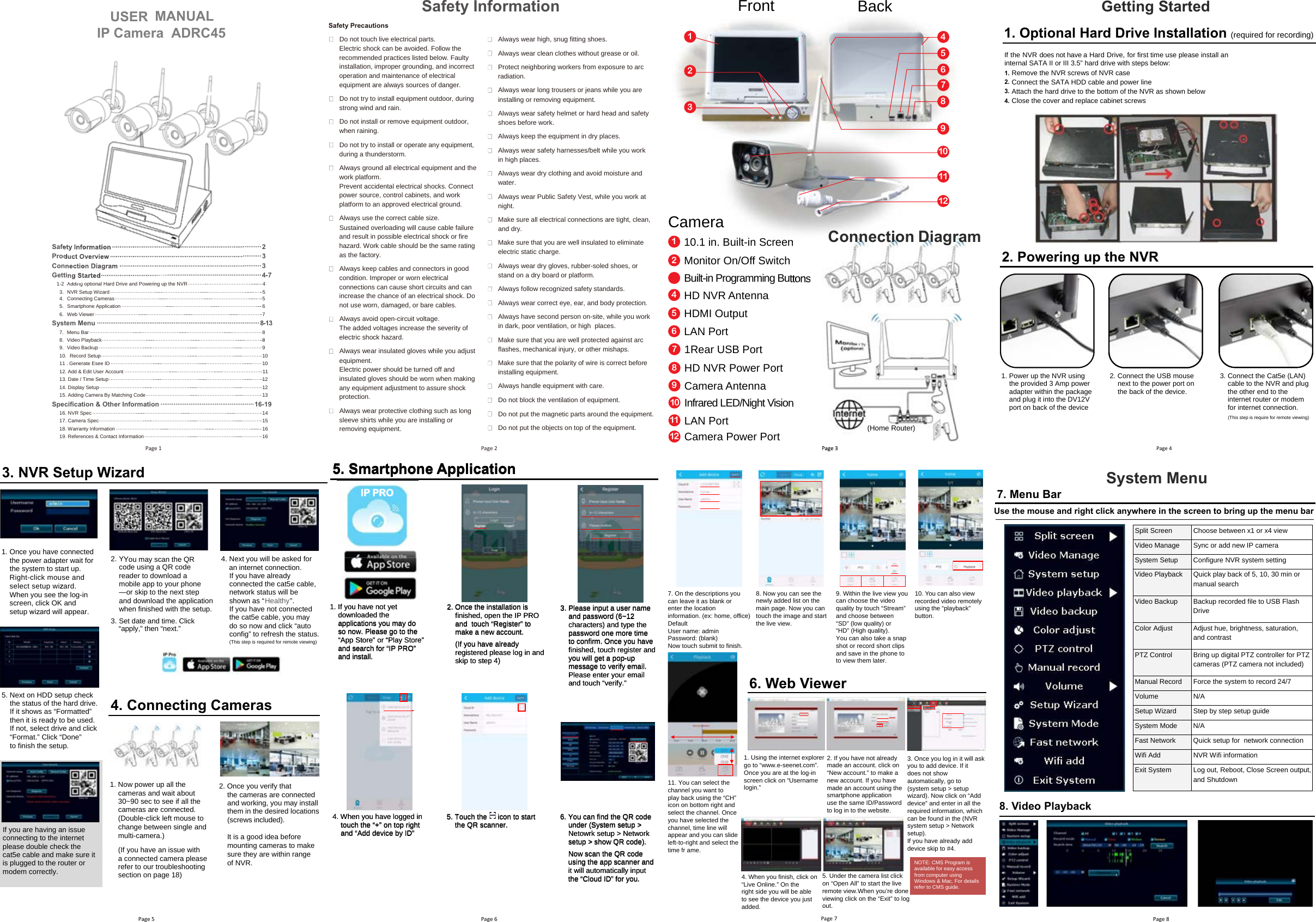
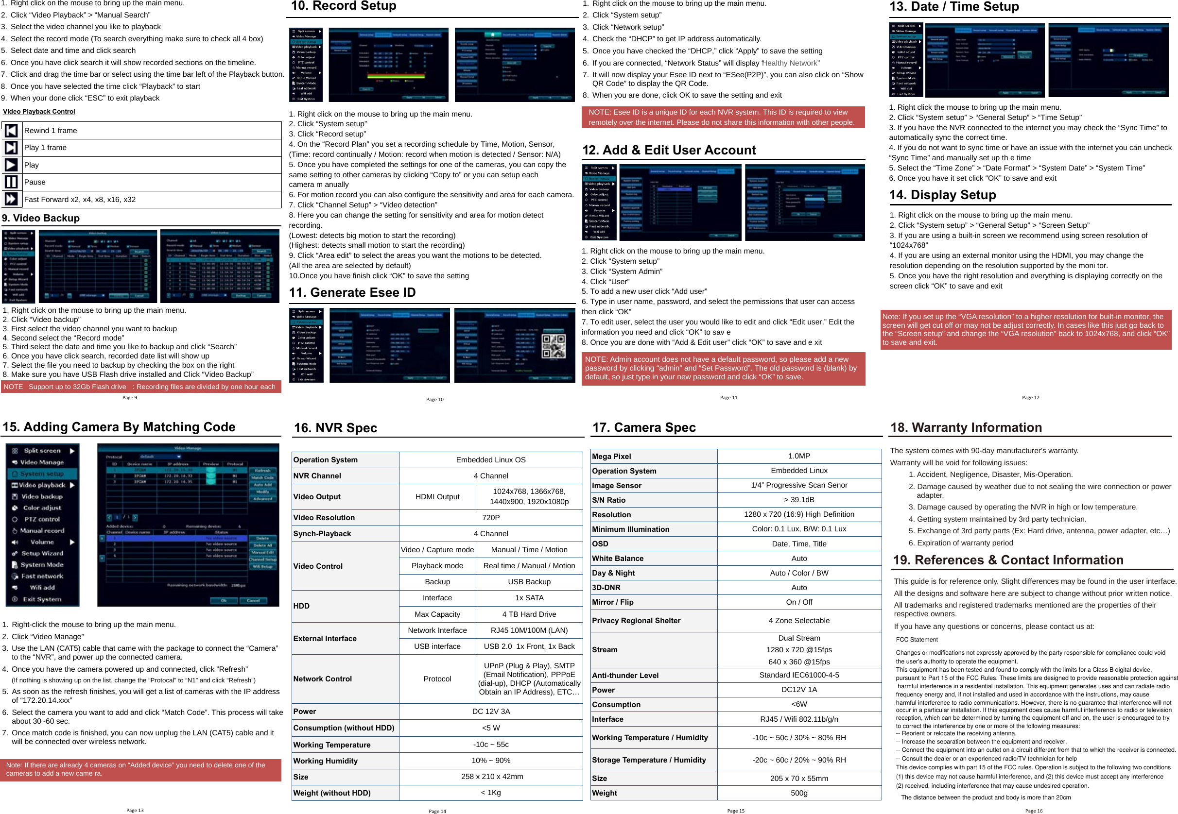
Users Manual
Navigation menu
Upload a User Manual
Namespaces
Wiki Guide
HTML
PDF
Info
Views
User Manual
Discussion / Help
Navigation