Atoms Labs ADRC45HD IP Camera User Manual
Atoms Labs LLC IP Camera Users Manual
Users Manual
Safety Information ················································································ 2
Product Overview ················································································· 3
Connection Diagram ············································································ 3
7-4 ······················································································ d etratS g nitteG
1-2 Adding optional Hard Drive and Powering up the NVR ············ · ······························· · ······ 4 ·
3. NVR Setup Wiz ard ······························· · ······························· · ······························· · ·········· · 5
4. Connecting Cameras ······························· · ······························· · ······························· · ······· · 5
5. Smartphone Application ······························· · ······························· · ······························ · · · 6
6. Web Viewer ······························· · ······························· · ······························· · ··················· · 7
System Menu ······················································································· 8-13
7. Menu Bar ······························· · ······························· · ······························· · ····················· · 8
8. Video Playback ······························· · ······························· · ······························· · ················ · 8
9. Video Backup ······························· · ······························· · ······························· · ················ · 9
10. Record Setup ······························· · ······························· · ······························· · ················ · 10
11 . Generate Esee ID ······························· · ······························· · ······························· · ·········· 10
12. Add & Edit User Account ······························· · ······························· · ···························· · · 11
13. Date / Time Setup ······························· · ······························· · ······························· · ··········· · 12
14. Display Setup ······························· · ······························· · ······························· · ················ · 12
15. Adding Camera By Matching Code ······························· · ······························· · ··············· · 13
Specification & Other Information ·················································· 16-19
16. NVR Spec ······························· · ······························· · ······························· · ···················· · 14
17. Camera Spec ······························· · ······························· · ······························· · ················ · 15
18. Warranty Information ······························· · ······························· · ······························· · ······ · 16
19. References & Contact Information ······························· · ······························· · ················ · 16
Safety Precautions
Do not touch live electrical parts.
Electric shock can be avoided. Follow the
recommended practices listed below. Faulty
installation, improper grounding, and incorrect
operation and maintenance of electrical
equipment are always sources of danger.
Do not try to install equipment outdoor, during
strong wind and rain.
Do not install or remove equipment outdoor,
when raining.
Do not try to install or operate any equipment,
during a thunderstorm.
Always ground all electrical equipment and the
work platform.
Prevent accidental electrical shocks. Connect
power source, control cabinets, and work
platform to an approved electrical ground.
Always use the correct cable siz e.
Sustained overloading will cause cable failure
and result in possible electrical shock or fire
haz ard. Work cable should be the same rating
as the factory.
Always keep cables and connectors in good
condition. Improper or worn electrical
connections can cause short circuits and can
increase the chance of an electrical shock. Do
not use worn, damaged, or bare cables.
Always avoid open-circuit voltage.
The added voltages increase the severity of
electric shock haz ard.
Always wear insulated gloves while you adjust
equipment.
Electric power should be turned off and
insulated gloves should be worn when making
any equipment adjustment to assure shock
protection.
Always wear protective clothing such as long
sleeve shirts while you are installing or
removing equipment.
Always wear high, snug fitting shoes.
Always wear clean clothes without grease or oil.
Protect neighboring workers from exposure to arc
radiation.
Always wear long trousers or jeans while you are
installing or removing equipment.
Always wear safety helmet or hard head and safety
shoes before work.
Always keep the equipment in dry places.
Always wear safety harnesses/belt while you work
in high places.
Always wear dry clothing and avoid moisture and
water.
Always wear Public Safety Vest, while you work at
night.
Make sure all electrical connections are tight, clean,
and dry.
Make sure that you are well insulated to eliminate
electric static charge.
Always wear dry gloves, rubber-soled shoes, or
stand on a dry board or platform.
Always follow recogniz ed safety standards.
Always wear correct eye, ear, and body protection.
Always have second person on-site, while you work
in dark, poor ventilation, or high places.
Make sure that you are well protected against arc
flashes, mechanical injury, or other mishaps.
Make sure that the polarity of wire is correct before
installing equipment.
Always handle equipment with care.
Do not block the ventilation of equipment.
Do not put the magnetic parts around the equipment.
Do not put the objects on top of the equipment.
Safety Information Front
Camera
Back
1
3
2
3
4
5
6
7
8
9
10
11
12
5. Next on HDD setup check
the status of the hard drive.
If it shows as “Formatted”
then it is ready to be used.
If not, select drive and click
“Format.” Click “Done”
to finish the setup.
If you are having an issue
connecting to the internet
please double check the
cat5e cable and make sure it
is plugged to the router or
modem correctly.
4. Connecting Cameras
1. Now power up all the
cameras and wait about
30~90 sec to see if all the
cameras are connected.
(Double-click left mouse to
change between single and
multi-camera.)
(If you have an issue with
a connected camera please
refer to our troubleshooting
section on page 18)
2. Once you verify that
the cameras are connected
and working, you may install
them in the desired locations
(screws included).
It is a good idea before
mounting cameras to make
sure they are within range
of NVR.
3. NVR Setup Wizard
2. Y You may scan the QR
3. Set date and time. Click
“apply,” then “next.”
code using a QR code
reader to download a
mobile app to your phone
— or skip to the next step
and download the application
when finished with the setup.
1. Once you have connected
the power adapter wait for
the system to start up.
Right-click mouse and
select setup wizzard.
When you see the log-in
screen, click OK and
setup wizard will appear.
4. Next you will be asked for
an internet connection.
If you have already
connected the cat5e cable,
network status will be
shown as “Healthy”.
If you have not connected
the cat5e cable, you may
do so now and click “auto
config” to refresh the status.
(This step is required for remote viewing)
IP PRO
1. If you have not yet
downloaded the
applications you may do
so now. Please go to the
“App Store” or “Play Store”
and search for “IP PRO”
and install.
2. Once the installation is
finished, open the IP PRO
and touch “Register” to
make a new account.
(If you have already
registered please log in and
skip to step 4)
3. Please input a user name
and password (6~12
characters) and type the
password one more time
to confirm. Once you have
finished, touch register and
you will get a pop-up
message to verify email.
Please enter your email
and ”.yfirev“ hcuot
4. When you have logged in
touch the “+ ” on top right
and “Add device by ID”
5. Touch the icon to start
the QR scanner. 6. Y ou can find the QR code
under (System setup >
Netowrk setup > Network
setup > show QR code).
Now scan the QR code
using the app scanner and
it will automatically input
the “Cloud ID” for you.
5. Smartphone Application
II
I
PP
P
P P
P
RR
R
OO
O
5. Smartphone Application5. Smartphone Application
5. Smartphone Application
IP PRO
1. If you have not yet
downloaded the
applications you may do
so now. Please go to the
“App Store” or “Play Store”
and search for “IP PRO”
and install.
2. Once the installation is
finished, open the IP PRO
and touch “Register” to
make a new account.
(If you have already
registered please log in and
skip to step 4)
3. Please input a user name
and password (6~12
characters) and type the
password one more time
to confirm. Once you have
finished, touch register and
you will get a pop-up
message to verify email.
Please enter your email
and ”.yfirev“ hcuot
4. When you have logged in
touch the “+ ” on top right
and “Add device by ID”
5. Touch the icon to start
the QR scanner.
5. Touch the icon to start 5. Touch the icon to start
5. Touch the icon to start
5. Touch the icon to start 5. Touch the icon to start
5. Touch the icon to start
5. Touch the icon to start 5. Touch the icon to start
5. Touch the icon to start
5. Touch the icon to start 5. Touch the icon to start
5. Touch the icon to start
5. Touch the icon to start
5. Touch the icon to start
5. Touch the icon to start
5. Touch the icon to start
5. Touch the icon to start
5. Touch the icon to start 5. Touch the icon to start
5. Touch the icon to start
5. Touch the icon to start 5. Touch the icon to start
5. Touch the icon to start
5. Touch the icon to start
5. Touch the icon to start
5. Touch the icon to start
5. Touch the icon to start
5. Touch the icon to start
6. Y ou can find the QR code
under (System setup >
Netowrk setup > Network
setup > show QR code).
Now scan the QR code
using the app scanner and
it will automatically input
the “Cloud ID” for you.
5. Smartphone Application
USER
IP Camera ADRC45
MANUAL
Safety Information ················································································ 2Safety Information ················································································ 2
Safety Information ················································································ 2
Product Overview ················································································· 3 Product Overview ················································································· 3
Product Overview ················································································· 3
Connection Diagram ············································································ 3 Connection Diagram ············································································ 3
Connection Diagram ············································································ 3
7-4 ······················································································ d etratS g nitteG 7-4 ······················································································ d etratS g nitteG
7-4 ······················································································ d etratS g nitteG
A A
A
ddingdding
dding
Page 1 Page 2
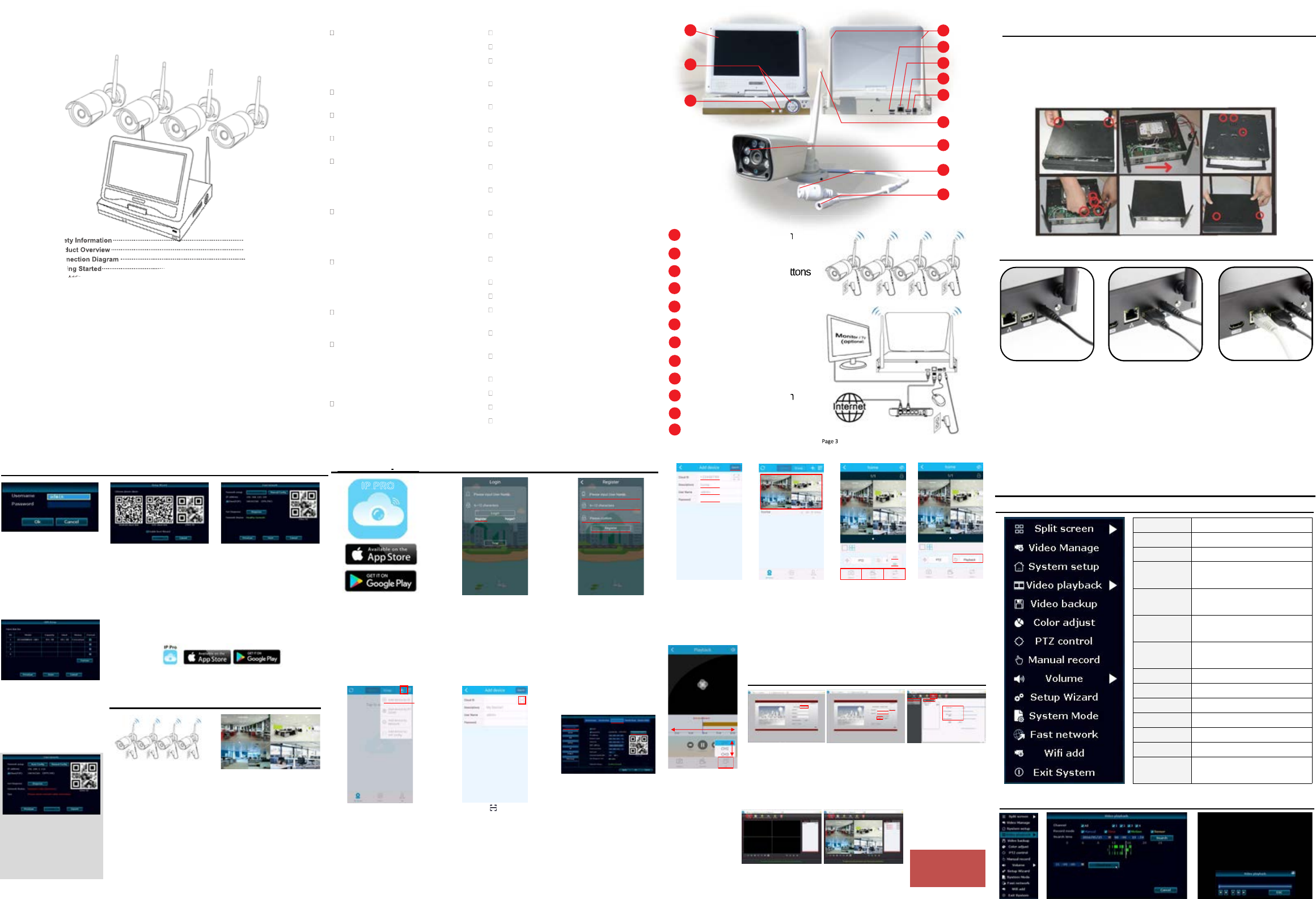
10.1 in. Built-in Screen
1
Monitor On/Off Switch
2
Built-in Programming Buttons
HD NVR Antenna
4
HDMI Output
5
LAN Port
6
1Rear USB Port
7
HD NVR Power Port
8
Camera Antenna
9
Infrared LED/Night Vision
10
LAN Port
11
Camera Power Port
12
Page 3
10.1 in. Built-in Screen10.1 in. Built-in Screen
10.1 in. Built-in Screen
g Buttonsg Buttons
g Buttons
onon
on
Page 3Page 3
Page 3
Connection Diagram
(Home Router)
2. Powering up the NVR
1. Power up the NVR using
the provided 3 Amp power
adapter within the package
and plug it into the DV12V
port on back of the device
2. Connect the USB mouse
next to the power port on
the back of the device.
3. Connect the Cat5e (LAN)
cable to the NVR and plug
the other end to the
internet router or modem
for internet connection.
(This step is require for remote viewing)
Getting Started
1. Optional Hard Drive Installation (required for recording)
If the NVR does not have a Hard Drive, for first time use please install an
internal SATA II or III 3.5” hard drive with steps below:
Remove the NVR screws of NVR case
Connect the SATA HDD cable and power line
Attach the hard drive to the bottom of the NVR as shown below
Close the cover and replace cabinet screws
1.
2.
3.
4.
Page 4
Page 5 Page 6 Page 7
7. On the descriptions you
can leave it as blank or
enter the location
information. (ex: home, office)
Default
User name: admin
Password: (blank)
Now touch submit to finish.
8. Now you can see the
newly added list on the
main page. Now you can
touch the image and start
the live view.
9. Within the live view you
can choose the video
quality by touch “Stream”
and choose between
“SD” (low quality) or
“HD” (High quality).
Y ou can also take a snap
shot or record short clips
and save in the phone to
to view them later.
11. Y ou can select the
channel you want to
play back using the “CH”
icon on bottom right and
select the channel. Once
you have selected the
channel, time line will
appear and you can slide
left-to-right and select the
time fr ame.
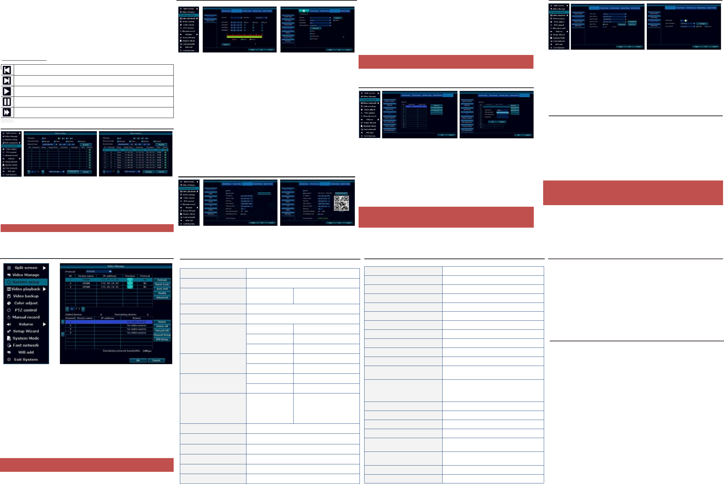
7. Menu Bar
8. Video Playback
System Menu
Split Screen Choose between x1 or x4 view
Video Manage Sync or add new IP camera
System Setup Configure NVR system setting
Video Playback Quick play back of 5, 10, 30 min or
manual search
Video Backup Backup recorded file to USB Flash
Drive
Color Adjust Adjust hue, brightness, saturation,
and contrast
PTZ Control Bring up digital PTZ controller for PTZ
cameras (PTZ camera not included)
Manual Record Force the system to record 24/7
Volume N/A
Setup Wiz ard Step by step setup guide
System Mode N/A
Fast Network Quick setup for network connection
Wifi Add NVR Wifi information
Exit System Log out, Reboot, Close Screen output,
and Shutdown
10. Y ou can also view
recorded video remotely
using the “playback”
button.
6. Web Viewer
1. Using the internet explorer
go to “www.e-seenet.com”.
Once you are at the log-in
screen click on “Username
login.”
2. If you have not already
made an account. click on
“New account.” to make a
new account. If you have
made an account using the
smartphone application
use the same ID/Password
to log in to the website.
3. Once you log in it will ask
you to add device. If it
does not show
automatically, go to
(system setup > setup
wiz ard). Now click on “Add
device” and enter in all the
required information, which
can be found in the (NVR
system setup > Network
setup).
If you have already add
device skip to # 4.
4. When you finish, click on
“Live Online.” On the
right side you will be able
to see the device you just
added.
5. Under the camera list click
on “Open All” to start the live
remote view.When you’re done
viewing click on the “Exit” to log
out.
NOTE: CMS Program is
available for easy access
from computer using
Windows & Mac. For details
refer to CMS guide.
Use the mouse and right click anywhere in the screen to bring up the menu bar
Page 8
Page 9
1. Right click on the mouse to bring up the main menu.
2. Click “Video Playback” > “Manual Search”
3. Select the video channel you like to playback
4. Select the record mode (To search everything make sure to check all 4 box)
5. Select date and time and click search
6. Once you have click search it will show recorded sections on the timeline.
7. Click and drag the time bar or select using the time bar left of the Playback button.
8. Once you have selected the time click “Playback” to start
9. When your done click “ESC” to exit playback
Rewind 1 frame
Play 1 frame
Play
Pause
Fast Forward x2, x4, x8, x16, x32
Video Playback Control
NOTE Support up to 32Gb Flash drive
: Recording files are divided by one hour each
1. Right click on the mouse to bring up the main menu.
2. Click “Video backup”
3. First select the video channel you want to backup
4. Second select the “Record mode”
5. Third select the date and time you like to backup and click “Search”
6. Once you have click search, recorded date list will show up
7. Select the file you need to backup by checking the box on the right
8. Make sure you have USB Flash drive installed and Click “Video Backup”
9. Video Backup
Page 10
1. Right click on the mouse to bring up the main menu.
2. Click “System setup”
3. Click “Record setup”
4. On the “Record Plan” you set a recording schedule by Time, Motion, Sensor,
(Time: record continually / Motion: record when motion is detected / Sensor: N/A)
5. Once you have completed the settings for one of the cameras, you can copy the
same setting to other cameras by clicking “Copy to” or you can setup each
camera m anually
6. For motion record you can also configure the sensitivity and area for each camera.
7. Click “Channel Setup” > “Video detection”
8. Here you can change the setting for sensitivity and area for motion detect
recording.
(Lowest: detects big motion to start the recording)
(Highest: detects small motion to start the recording)
9. Click “Area edit” to select the areas you want the motions to be detected.
(All the area are selected by default)
10.Once you have finish click “OK” to save the setting
10. Record Setup
11. Generate Esee ID
1. Right click on the mouse to bring up the main menu.
2. Click “System setup”
3. Click “Network setup”
4. Check the “DHCP” to get IP address automatically.
5. Once you have checked the “DHCP,” click “Apply” to save the s gnitte
6. If you are connected, “Network Status” will display “Healthy Network”
7. It will now display your Esee ID next to “ESee(P2P)”, you can also click on “Show
QR Code” to display the QR Code.
8. When you are done, click OK to save t tixe dna gnittes eh
NOTE: Esee ID is a unique ID for each NVR system. This ID is required to view
remotely over the internet. Please do not share this information with other people.
12. Add & Edit User Account
1. Right click on the mouse to bring up the main menu.
2. Click “System setup”
3. Click “System Admin”
4. Click “User”
5. To add a new user click “Add user”
6. Type in user name, password, and select the permissions that user can access
then click “OK”
7. To edit user, select the user you would like to edit and click “Edit user.” Edit the
information you need and click “OK” to sav e
8. Once you are done with “Add & Edit user” click “OK” to save and e xit
NOTE: Admin account does not have a default password, so please add a new
password by clicking “admin” and “Set Password”. The old password is (blank) by
default, so just type in your new password and click “OK” to save.
Page 11 Page 12
13. Date / Time Setup
1. Right click the mouse to bring up the main menu.
2. Click “System setup” > “General Setup” > “Time Setup”
3. If you have the NVR connected to the internet you may check the “Sync Time” to
automatically sync the correct time.
4. If you do not want to sync time or have an issue with the internet you can uncheck
“Sync Time” and manually set up th e time
5. Select the “Time Zone” > “Date Format” > “System Date” > “System Time”
6. Once you have it set click “OK” to save and exit
14. Display Setup
1. Right click on the mouse to bring up the main menu.
2. Click “System setup” > “General Setup” > “Screen Setup”
3. If you are using a built-in screen we recommend using screen resolution of
“1024x768”
4. If you are using an external monitor using the HDMI, you may change the
resolution depending on the resolution supported by the moni tor.
5. Once you have the right resolution and everything is displaying correctly on the
screen click “OK” to save and exit
Page 14
16. NVR Spec
Operation System Embedded Linux OS
NVR Channel 4 Channel
Video Output HDMI Output 1024x768, 1366x768,
1440x900, 1920x1080p
Video Resolution 720P
Synch-Playback 4 Channel
Video Control
Video / Capture mode Manual / Time / Motion
Playback mode Real time / Manual / Motion
Backup USB Backup
HDD
Interface 1x SATA
Max Capacity 4 TB Hard Drive
External Interface
Network Interface RJ45 10M/100M (LAN)
USB interface USB 2.0 1x Front, 1x Back
Network Control Protocol
UPnP (Plug & Play), SMTP
(Email Notification), PPPoE
(dial-up), DHCP (Automatically
Obtain an IP Address), ETC…
Power DC 12V 3A
Consumption (without HDD) <5 W
Working Temperature -10c ~ 55c
Working Humidity 10% ~ 90%
Size 258 x 210 x 42mm
Weight (without HDD) < 1Kg
Page 15
17. Camera Spec
Mega Pixel 1.0MP
Operation System Embedded Linux
Image Sensor 1/4” Progressive Scan Senor
S/N Ratio > 39.1dB
Resolution 1280 x 720 (16:9) High Definition
Minimum Illumination Color: 0.1 Lux, B/W: 0.1 Lux
OSD Date, Time, Title
White Balance Auto
Day & Night Auto / Color / BW
3D-DNR Auto
Mirror / Flip On / Off
Privacy Regional Shelter 4 Zone Selectable
Stream
Dual Stream
1280 x 720 @15fps
640 x 360 @15fps
Anti-thunder Level Standard IEC61000-4-5
Power DC12V 1A
Consumption <6W
Interface RJ45 / Wifi 802.11b/g/n
Working Temperature / Humidity -10c ~ 50c / 30% ~ 80% RH
Storage Temperature / Humidity -20c ~ 60c / 20% ~ 90% RH
Size 205 x 70 x 55mm
Weight 500g
Page 16
18. Warranty Information
The system comes with 90-day manufacturer’s .ytnarraw
:seussi gniwollof rof diov eb lliw ytnarraW
1. Accident, Negligence, Disaster, Mis-Operation.
2. Damage caused by weather due to not sealing the wire connection or power
adapter.
3. Damage caused by operating the NVR in high or low temperature.
4. Getting system maintained by 3rd party technician.
5. Exchange of 3rd party parts (Ex: Hard drive, antenna, power adapter, etc…)
6. Expiration of warranty period
19. References & Contact Information
This guide is for reference only. Slight differences may be found in the user interface.
All the designs and software here are subject to change without prior written notice.
All trademarks and registered trademarks mentioned are the properties of their
respective owners.
If you have any questions or concerns, please contact us at:
Note: If you set up the “VGA resolution” to a higher resolution for built-in monitor, the
screen will get cut off or may not be adjust correctly. In cases like this just go back to
the “Screen setup” and change the “VGA resolution” back to 1024x768, and click “OK”
to save and exit.
Page 13
15. Adding Camera By Matching Code
1. Right-click the mouse to bring up the main menu.
2. Click “Video Manage”
3. Use the LAN (CAT5) cable that came with the package to connect the “Camera”
to the “NVR”, and power up the connected camera.
4. Once you have the camera powered up and connected, click “Refresh”
(If nothing is showing up on the list, change the “Protocal” to “N1” and click “Refresh”)
5. As soon as the refresh finishes, you will get a list of cameras with the IP address
of “172.20.14.xx ”x
6. Select the camera you want to add and click “Match Code”. This process will take
about 30~60 sec.
7. Once match code is finished, you can now unplug the LAN (CAT5) cable and it
will be connect .krowten sseleriw revo de
Note: If there are already 4 cameras on “Added device” you need to delete one of the
cameras to add a new came ra.
FCC Statement
Changes or modifications not expressly approved by the party responsible for compliance could void
the user's authority to operate the equipment.
This equipment has been tested and found to comply with the limits for a Class B digital device,
pursuant to Part 15 of the FCC Rules. These limits are designed to provide reasonable protection against
harmful interference in a residential installation. This equipment generates uses and can radiate radio
frequency energy and, if not installed and used in accordance with the instructions, may cause
harmful interference to radio communications. However, there is no guarantee that interference will not
occur in a particular installation. If this equipment does cause harmful interference to radio or television
reception, which can be determined by turning the equipment off and on, the user is encouraged to try
to correct the interference by one or more of the following measures:
-- Reorient or relocate the receiving antenna.
-- Increase the separation between the equipment and receiver.
-- Connect the equipment into an outlet on a circuit different from that to which the receiver is connected.
-- Consult the dealer or an experienced radio/TV technician for help
This device complies with part 15 of the FCC rules. Operation is subject to the following two conditions
(1) this device may not cause harmful interference, and (2) this device must accept any interference
(2) received, including interference that may cause undesired operation.
The distance between the product and body is more than 20cm