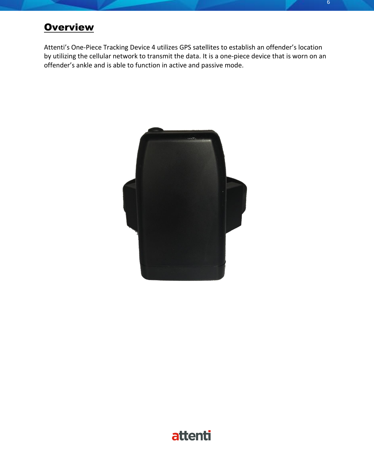
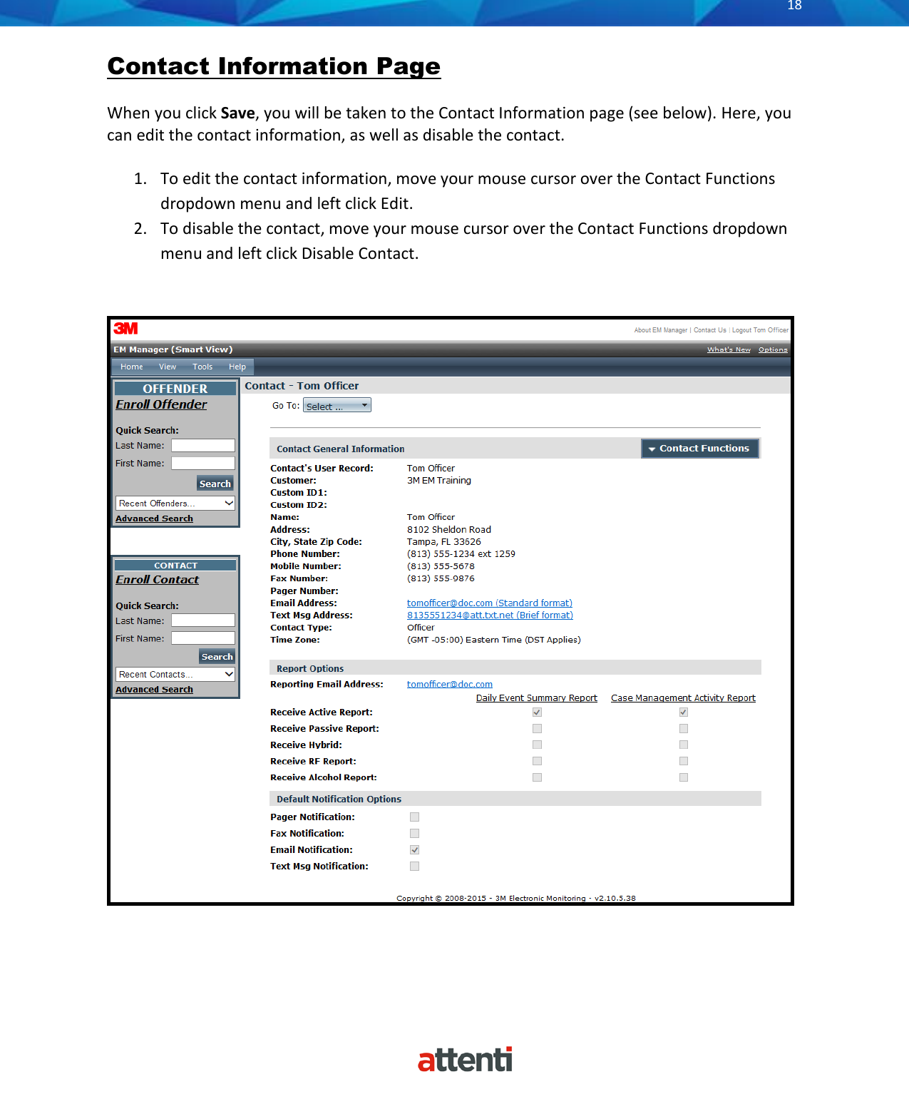
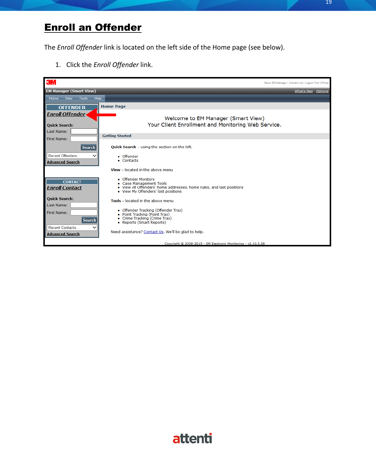
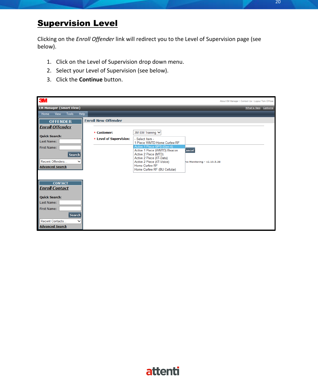
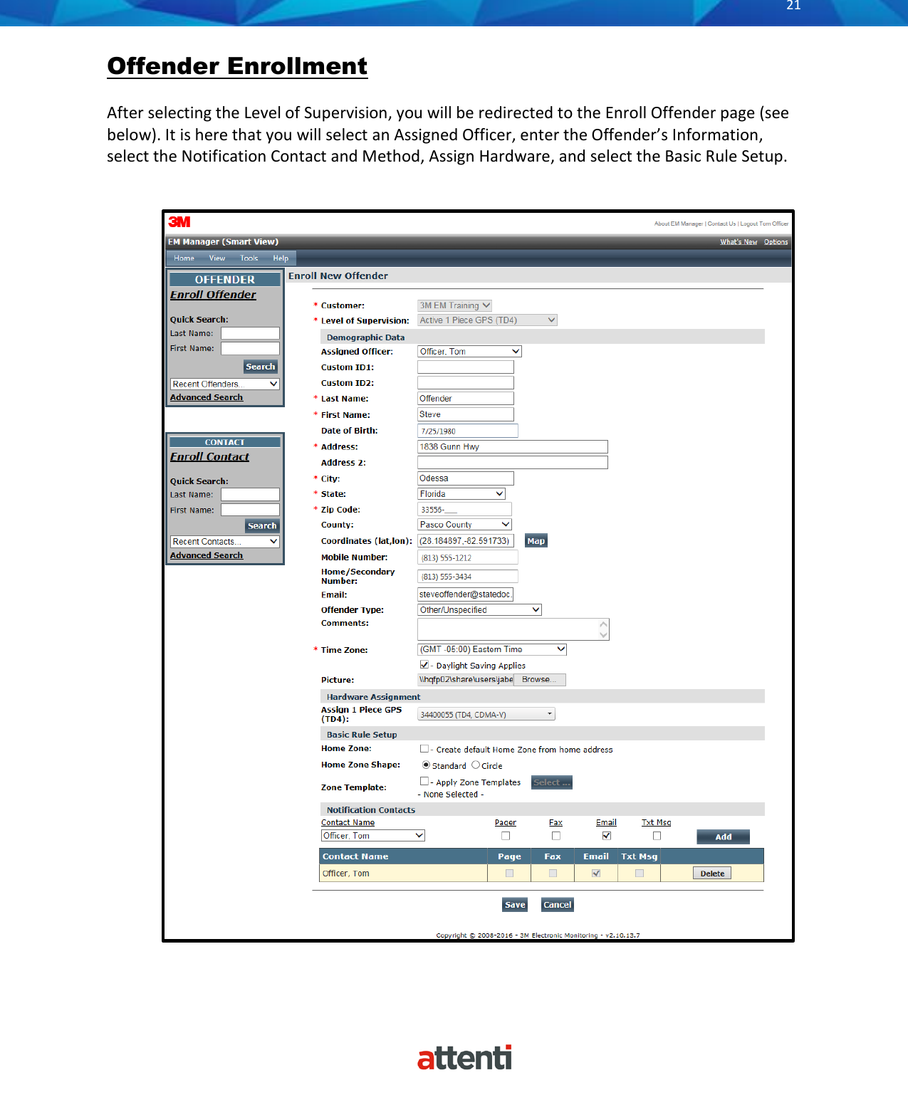
Attenti US TSSDW40143 1-Piece (3G Gen 4) Offender Tracking Device User Manual

Attenti 1-Piece (3G Gen 4) Offender Tracking Device

User manual

       1 Piece (Gen 4) User Manual  Attenti One-Piece Tracking Device 4 User Manual  January 16, 2018
      2          Copyright ©2018 Attenti. All rights reserved. No  part  of  this  publication  may  be  reproduced,  stored  in  a  retrieval  system,  or transmitted,  in  any  form  or  by  any  means,  electronic,  mechanical,  photocopying, recording, or otherwise, without the prior written permission of Attenti. The  information  in  this  document  is  subject  to  change  without  notice.  The  software mentioned in this document is furnished under license and may only be used or copied in accordance with the terms of such license. Contact software manufacturers directly for  terms  of  software  licenses  for  any  software  mentioned  in  this  document  not originating from Attenti. All  brand  or  product  names  are  the  trademarks  or  registered  trademarks  of  their respective holders.
      3          SAFETY INFORMATION  Please read, understand, and follow all safety information contained in these instructions prior to the use of this Attenti device.  Retain these instructions for future reference.  Intended Use:  This Attenti device is part of an electronic monitoring system, which performs data transfer using cellular network to a monitoring platform. This device has not been tested for and is not intended for use on airplanes, in hazardous environments, in healthcare facilities, or where cellular phones or other intentional transmitters are restricted.  Safety information for Trained Customer (e.g., officer, agency representative, ministry of justice) and Offender.   WARNING • Avoid placing a device next to an implanted electronic device (e.g., don’t carry the device in a shirt or jacket pocket directly near an implanted device).  • To reduce the risks associated with fire or explosion: - Do not intentionally open or damage the device. - Do not enter areas with potentially explosive atmosphere. Potentially explosive areas are often, but not always, clearly marked.  • To reduce the risks associated with hazardous voltage: - Do not modify AC/DC power adapter plug. - Do not force the power plug into an outlet where it does not fit. - Use only a Attenti provided power adapter to recharge or power the device. - Do not unplug AC/DC adapter by power cord. Handle the adapter by the body only. - Do not modify, decorate, or attempt to service the device. Return to Attenti authorized personnel or location for repair or service. There are no user serviceable parts. - Do not attempt to charge the device using an outdoor outlet. Only use the AC/DC adapter indoors. - Do not expose power adapter to rain, steam or wet conditions.  Explanation of Signal Word Consequences   WARNING:   Indicates a hazardous situation which, if not avoided, could result in serious injury or death    CAUTION:   Indicates a hazardous situation which, if not avoided, could result in minor or moderate injury and/or property damage.               NOTICE:   Indicates a situation which, if not avoided, could result in property damage.
      4           CAUTION • To reduce the risks associated with hot surfaces: - Do not touch thermal pads on device or charger if charging is interrupted.  Safety information for Trained Customer only.   WARNING • To reduce the risks associated with fire or explosion: - Do not attempt to access or replace battery. Battery is not user-replaceable. The device shall be opened by Attenti authorized service only. - Ensure storage temperature of device is within the range as specified in device manual.  CAUTION • To reduce the risks associated with sharp points: - Use caution when handling pin trays.  Safety information for Offender only.   WARNING • To reduce the risks associated with fire or explosion: - Risk of explosion if battery is replaced by an incorrect type. Dispose of used batteries according to the instructions. - Do not use device outside of the operation temperature range specified in device manual. Contact the agency representative from which you are monitored to get operation temperature range.  • To reduce the risks associated with hazardous voltage: - If the device or power cord becomes damaged, contact the agency representative from which you are monitored.  NOTICE • Only authorized personnel can turn off or remove the device.
      5          Table of Contents  Overview ................................................................................................................................................ 6 Operating Features ................................................................................................................................ 7 Operating Details ................................................................................................................................... 9 Communication ...................................................................................................................................... 9 LEDs ...................................................................................................................................................... 10 Enrollment ........................................................................................................................................... 14 Enroll a Contact .................................................................................................................................... 15 Contact Information Page .................................................................................................................. ..18 Enroll an Offender ................................................................................................................................ 19 Supervision Level ................................................................................................................................. 20 Map Offender’s Address ...................................................................................................................... 24 Offender General Information Page .................................................................................................... 25 Create Schedule for Home Inclusion Zone ........................................................................................... 26 Create Exclusion Zone .......................................................................................................................... 30 Attaching the 1 Piece ........................................................................................................................... 33 Unassign Hardware .............................................................................................................................. 38 Removing the 1 Piece ........................................................................................................................... 42 Appendix .............................................................................................................................................. 44 Rule Definitions .................................................................................................................................... 44 1 Piece Self Test ................................................................................................................................... 46
      6          Overview  Attenti’s One-Piece Tracking Device 4 utilizes GPS satellites to establish an offender’s location by utilizing the cellular network to transmit the data. It is a one-piece device that is worn on an offender’s ankle and is able to function in active and passive mode.
      7          1 Piece Operating Features  Battery Life: The device should be given a full charge (4.2 volts) to supply a full day of battery life. It takes approximately 2 to 2 ½ hours to acquire a full charge. The battery will last approximately 24-30 hours if fully charged. The daily life of the battery is dependent upon the call-in interval of the device, how often it goes to rest, and how many violations are created. The battery must be charged each day in order to continue to track your offender’s locations.   Note: Battery tests are conducted using specific Attenti devices in controlled testing environments. Actual performance and results may be affected by cellular network, location, signal strength, feature configuration, usage, and many other factors. Battery life and charge cycles vary by use and settings.  Vibrate feature: The 1 Piece will vibrate upon violation and when the device receives an alert from the officer.  If the offender causes a violation, the 1 Piece will vibrate three times consecutively and once every ten minutes until they clear the violation.  If the officer sends the offender a notification (an alert) to contact them, the 1 Piece will vibrate for ten consecutive seconds. As soon as the offender acknowledges the notification, the vibration will stop. All three LED lights will be flashing red to indicate that the offender needs to acknowledge the officer’s notification.  If the offender doesn’t acknowledge the notification, then every ten minutes it will vibrate once until they acknowledge the notification.  Storing GPS Points: The 1 Piece will store an offender’s location (GPS point) when in motion (moving) every minute. If the 1 Piece does not experience any motion for two consecutive minutes, the 1 Piece will go to “rest” and collect a GPS point every hour instead of each minute. As soon as any motion is generated, the 1 Piece will resume recording points on a minute-to-minute basis. However, if the offender causes a geographic zone violation and is in motion, the 1 Piece will begin to store a point every 15 seconds.   Call-in intervals: The 1 Piece will contact Attenti every hour while in active mode and every six hours while in passive mode. While in active mode, it will also contact Attenti immediately upon violation.  Automatic Redial: If the 1 Piece is unable to communicate with Attenti because of poor cellular coverage, it will continue to try to call and download its information until it is successful.  Waterproof: The 1 Piece is waterproof down to 66 feet.
      8          1 Piece Operating Features, cont.  Rubber strap: The 1 Piece strap is designed to last nine months to one year.   Magnetized Charger: The 1 Piece has a magnetized charger to prevent an accidental disconnect when the battery is being recharged.
      9          1 Piece Operating Details Communication  The 1 Piece has a SIM card, which is similar to the data transmitter/receiver found in most cellular phones. The 1 Piece uses the SIM card to transmit and download the GPS points and alarms it has recorded to Attenti’s servers. The call-in intervals are determined by the agency’s contract specifications. Examples may be hourly, every six hours, or immediately upon alarm.  Active Mode:  • The standard 1 Piece call-in interval is once every hour while in compliance. • The 1 Piece will call Attenti as soon as a violation occurs.  Passive Mode:  • The standard 1 Piece call-in interval is once every six hours. • The 1 Piece will not call Attenti when a violation occurs. The officer will only be made aware of violations when they view the GPS maps or the Daily Event Summary Report (DESR) that is emailed to the officer.  • Violations will also be displayed in Case Management and on the Offender Monitor.
      10          Operating Details  LEDs  There are three LEDs on the top of the 1 Piece, identified as Power, GPS, and Zone. The three LEDs work separately and provide the offender with information. The 1 Piece will vibrate to provide an indication that the offender must look at the LEDs.
      11          Operating Details  LEDs  Power  This LED indicates the condition of the 1 Piece battery.  Prior to Activation:  Before activating the device, the officer should conduct a battery test. To do this, simply hold down the silver activation button for three seconds and observe the condition of the Battery LED.  • If the “PWR” LED is green, there is a sufficient charge to activate the 1 Piece. • If the “PWR” LED is red, or does not light up at all, the 1 Piece needs to be charged.   After Activation:  • If the “PWR” LED is blinking green, there is a sufficient charge. • If the “PWR” LED is blinking red, the 1 Piece needs to be charged.  1 Piece on Charger:  When the 1 Piece is connected to the charger, the Power LED will be solid (not flashing) green or red.  • If the LED is red: The 1 Piece is not fully charged and should not be disconnected from the charger • If the LED is green: The 1 Piece battery has been completely charged and the charger may be disconnected • When the 1 Piece is connected to the charger, it will vibrate once indicating a good connection.  When the battery is fully charged, the 1 Piece will vibrate once indicating that it is okay to remove from the charger.
      12          Operating Details  LEDs  GPS  Officer:  • During activation, the officer will see this LED flashing green in unison with the flashing “Zone” LED.   Offender:  • In normal conditions, the GPS LED will be off. • The offender will see this LED flashing red to indicate a Motion No GPS warning or violation. When the violation has cleared, the LED will stop blinking.
      13          Operating Details  LEDs  Zone  Officer:  • During activation, the officer will see this LED flashing green in unison with the flashing “GPS” LED.  Offender:  • In normal conditions, the Zone LED will be off. • The offender will see this LED flashing red to indicate an Inclusion or Exclusion Zone warning and/or violation. When the violation has been cleared, the LED will stop blinking.
      14          Enrollment  EM Manager (Smart  View) Log In  To access the secure website, go to https://smartview.ptm.com. You will be required to enter a user ID and password.  When using EM Manager (Smart View) for the first time, you will create your own password.  Enter your User ID (often your three initials and last four digits of your social security number), the temporary password that was emailed to you, and click OK. The next screen will tell you that your password has expired.  Create your password, (the password you select must contain at least 8 characters), and click OK. You will now be logged into EM Manager (Smart View).  Note: If you forget your password, click the Forgot Password link. A new temporary password will be emailed to you. To create your new password, follow the instructions contained within the email.
      15          Enroll a Contact The Enroll Contact link is located on the left side of the Home page (see below). It is here that you will enter the officer’s information (name, address, phone number, etc.), report types, and default notification settings. 1. Click the Enroll Contact link on the left side of the Home page.  2. You  will  be  redirected  to  the  Enroll  Contact  page  (see  below).  Enter  all  Contact information. 3. Click Save.
      16          Enroll a Contact, Cont.
      17          Enroll a Contact, Cont.  Demographic Data Enter the Contact’s information. • All fields with red asterisks (*) are required fields. Report Options Enter an email address where the selected reports will be sent. Choose Daily Event Summary Report and/or Case Management Activity Report. Default Notification Options Select the type of Notification you would like to be your default method. The notification method is dependent upon the information that you enter into the Notification Email or Text Message fields. • Pager • Fax • E-mail • Text Message  Finish Enrollment When you have completed the form, click Save.
      18          Contact Information Page  When you click Save, you will be taken to the Contact Information page (see below). Here, you can edit the contact information, as well as disable the contact.  1. To edit the contact information, move your mouse cursor over the Contact Functions dropdown menu and left click Edit. 2. To disable the contact, move your mouse cursor over the Contact Functions dropdown menu and left click Disable Contact.
      19          Enroll an Offender The Enroll Offender link is located on the left side of the Home page (see below).  1. Click the Enroll Offender link.
      20          Supervision Level  Clicking on the Enroll Offender link will redirect you to the Level of Supervision page (see below).   1. Click on the Level of Supervision drop down menu. 2. Select your Level of Supervision (see below). 3. Click the Continue button.
      21          Offender Enrollment  After selecting the Level of Supervision, you will be redirected to the Enroll Offender page (see below). It is here that you will select an Assigned Officer, enter the Offender’s Information, select the Notification Contact and Method, Assign Hardware, and select the Basic Rule Setup.
      22          Offender Enrollment, Cont.  Demographic Data  1. Enter the Offender's Information. • All fields with red asterisks (*) are required fields 2. Click the Map button to geo-code the offender’s address. This is required if you are creating a Home Inclusion Zone for the offender. 3. Select the Offender Type. 4. Select the Time Zone. Hardware Assignment 5. Locate the serial number on the device. 6. Click on the drop down menu and select that serial number for the device.  Basic Rule Setup 7. Click the box next to Create Default Home Zone from Home Address. For information on how to edit the schedule for the Home Rule, refer to page 26. 8. Choose the appropriate Contact from the Notification Contact drop down list. The selected Contact will be notified for all rules. 9. Click the Add button. 10. Select the type of Notification (if you haven’t chosen your Default Notification Method on your Contact record) • Pager • Fax • E-mail • Text Message  Finish Enrollment 11.  When you have completed entering the information, click Save.
      23          Map Offender’s Address  Clicking the Map button on the Offender Enrollment screen will generate a map that displays a pushpin at the offender’s residence. Ensure that the pushpin location is correct and click the Submit button. It is also possible to edit the location by clicking the Edit Pushpin button.
      24          Offender General Information Page  When Enrollment has been completed, you will be redirected to the Offender General Information page (see below).  Here, you can Edit Offender Information, Disable the Offender, View GPS Points, Unassign Hardware, Edit Rules, Send Alerts, and Download Points.
      25          Create Schedule for Home Inclusion Zone 1. Click on the Home Rule (see below).
      26          Create Schedule for Home Inclusion Zone, Cont. 2. Move your cursor over the Rules Functions drop-down menu and left click Edit.
      27          Create Schedule for Home Inclusion Zone, Cont. 3. You will be redirected to the Edit Rule page. Scroll down to the Permanent Rule Schedule.
      28          Create Schedule for Home Inclusion Zone, Cont.  4. Each block represents a 30 minute increment of time.  Left-click and drag the cursor along the blocks during the times that the offender is required to be home. As you move the cursor, the blocks will turn blue. The white blocks that remain equal the times that the offender is allowed to be out of the home (see below). 5. Click the Save button.
      29          Create Exclusion Zone You can create an Exclusion Rule to ensure that the offender is not entering areas which are forbidden – such as schools, playgrounds, and victims’ residences.  1. Move your cursor over the Rule Functions menu (see below). This will generate the Rule Functions menu. 2. Click Add Zone.
      30          Create Exclusion Zone, Cont.   3. Choose a Zone Shape. 4. Choose Exclusion as the Zone Type. 5. Click the Continue button.
      31          Create Exclusion Zone, Cont.   6. Enter the Rule Name (school, playground, etc.). 7. Enter the address information and the zone size. The default is 600 ft. 8. Select Yes or No if you want to notify the offender upon violation.  9. Choose the appropriate Contact from the Notification Contact drop down list. The contact’s default notification method will appear selected. 10. Click the Add button. 11. Click the Map button.
      32          Create Exclusion Zone, Cont.   12. Ensure that the address and zone size is correct. 13. If you want to resize or move the zone, click the Move/Resize button. 14. If you move or resize the zone, click the Finish Move/Resize button. 15. Click the Submit button.
      33          Attaching the 1 Piece                         Step 2:  Press and hold the Activate Button on the top of the 1 Piece.   If the “PWR” LED is Green, proceed with activation.   If the “PWR” LED is Red or does not light up at all, the 1 Piece has not been sufficiently charged.  Step 3:  Push tamper plugs into the back of the brackets of the 1 Piece.   Be sure to insert the side without the tamper plug tab first (see above).   After the right side has been secured, press the left side of the tamper plug down.  Step 1:  Charge the 1 Piece for a minimum of two hours and remove from the charger.
      34          Attaching the 1 Piece, cont.                  Step 4:  Place the pin tray on a flat, stable surface (such as a desk) and push one end of the strap completely into the pin tray.    Step 6:   Insert strap with attached pin tray into one side of the 1 Piece until it snaps in place.    Step 5:  Examine the strap to ensure that it is cut evenly and that there is no gap between the end of the strap and the edge of the pin tray.
      35          Attaching the 1 Piece, cont.           Step 8:  Wrap the strap around the offender’s leg and measure to the edge of the bracket, so that it allows approximately ¼ inch of space between the offender’s leg and the strap to ensure comfort.    Step 9:  Use the strap cutters and cut the strap according to the measurement.   Note: Ensure that the end of the strap has been cut evenly.  Step 7:  Place the 1 Piece on the offender’s leg, just above the ankle bone.
      36           Attaching the 1 Piece, cont.                                                                                                                                                                                                                                      Step 12:  Place the 1 Piece on the offender’s leg, just above the ankle bone. Wrap the strap around the offender’s leg and insert the strap with attached pin tray into the bracket until it snaps in place.         Step 10:  Place the remaining pin tray on a flat, stable surface (such as a desk) and push one end of the strap completely into the pin tray.    Step 11:  Examine the strap to ensure that it is cut evenly and that there is no gap between the end of the strap and the edge of the pin tray.
      37            Attaching the 1 Piece, Cont.     Step 13:  Ensure that all three lights (PWR, GPS, and ZONE) on top of the 1 Piece are off.       Step 14:  Press and hold the Activate Button on the top of the 1 Piece until it vibrates.  A.  The 1 Piece will vibrate once and the “PWR” LED will begin to blink green, indicating the 1 Piece is powered on.  B. The “GPS” and “ZONE” LED’s will blink green once every second. This indicates that the 1 Piece is attempting to make a wireless call.   C. The “GPS” and “ZONE” LEDs will blink green twice every second. This indicates that the 1 Piece is attempting to acquire GPS. The 1 Piece must now be taken outside to acquire GPS.  D. Once GPS has been acquired, the 1 Piece will vibrate three times.  The “PWR” LED will continue to blink green and the “GPS” and “ZONE” LEDs will stop blinking. This indicates that activation has been successfully completed.
      38          Unassigning Hardware  1. Move your cursor over the Hardware Functions dropdown menu and left click Unassign.  .
      39          Unassigning Hardware, Cont. 2. Click the checkbox next to the 1 Piece (see below). 3. Click on the drop-down menu and select a reason for unassignment. This is required.
      40          Unassigning Hardware, Cont.  4. Click the Save button. A popup will generate with a warning that the unassignment is immediate. 5. Click OK.
      41          Unassigning Hardware, Cont.  6. You will be returned to the Offender Information page, where the hardware will be pending unassignment. The device is now required to call Attenti and transmit its final data. The hardware will only be unassigned once this final call has occurred.
      42           Removing the 1 Piece                                          Step 2:  Use a flathead screwdriver to press on the center of the tamper plugs until the head of the screwdriver pierces the tamper plugs.  Step 3:  Use the screwdriver to remove the tamper plugs from the brackets.   Step 1:  Use the strap cutters to make a cut in the center of the strap. Remove the device from the offender’s leg.
      43          Removing the 1 Piece, cont.        Step 5:  While keeping the latch depressed, pull the strap with the attached pin trays out of each bracket. Discard the tamper plugs and straps.   Note: Do NOT reuse the tamper plugs.  Note: Do NOT remove tamper plugs from the brackets of the 1 Piece unless there is a strap with an attached pin tray inside the bracket.  Step 4:  Use the screwdriver to press down the latch attached to the pin tray.
      44          Appendix  Rule Definitions  1 Piece GPS (TD4) Battery  • The battery is getting low and the device needs to be charged. The device must be charged for a minimum of two hours daily (the hours do not have to be consecutive). When the battery needs to be charged, the device will vibrate three times consecutively and then once every ten minutes until connected to the charger. During this time, the Power LED will blink Red.  1 Piece GPS (TD4) Motion No GPS  • Occurs when the 1 Piece has lost GPS for five minutes and then accumulates excessive motion in a 60 minute period without receiving a signal from the GPS satellites. The device will vibrate three times consecutively and once every ten minutes until the violation has cleared by acquiring GPS. During this time, the GPS LED will blink Red.   1 Piece GPS (TD4) Strap  • The strap has been compromised or removed from the 1 Piece. There will not be any notifications to the offender that this has occurred, unless the officer selects the Notify Offender with Vibrate option on this rule.  1 Piece GPS (TD4) Unable to Connect  • The 1 Piece has a defined call-in interval that is determined by the contract. If the 1 Piece is unable to call Attenti at its defined call-in interval, a default 90 minute grace period will go into effect. If the default 90 minute grace period expires and the 1 Piece has still not called Attenti, the database will create this alarm.  This is normally due to poor cellular coverage in the area. The offender is not notified of the Unable to Connect alarm. Once the 1 Piece is able to use the cellular network to call in, it will report any violations that occurred during this time and download all tracking data.
      45          Rule Definitions, Cont.  1 Piece GPS (TD4) Tamper  • The 1 Piece has been compromised in some form. There will not be any notification to the offender that this has occurred, unless the officer selects the Notify Offender with Vibrate option on this rule.  Geographic Rules  Zone Rules- The offender has violated a Zone set up by the user. The device will vibrate three times consecutively and once every ten minutes while still in violation, if the Notify With Vibrate feature is checked. The Zone LED will blink Red.  • Inclusion Zone  o Geographic areas like home, work, or school where the offender is confined during an officer defined schedule.  • Exclusion Zone   o Geographic areas used to define off-limits areas to the offender.
      46          1 Piece Self Test  To Begin the 1 Piece Self Test:  • Make sure the 1 Piece is unassigned from any offenders. • Make sure the 1 Piece does NOT have a strap with a pin tray in it. • Make sure that the 1 Piece is in a good wireless and GPS location.  • Press and hold the Activate Button until the 1 Piece vibrates. • The PWR/ZONE/GPS LEDs will begin to blink green, verifying the test is in progress. • Only the Zone and GPS LEDs will be utilized for the test. • The test results will be displayed on the Zone/GPS LEDs within 10 minutes. • To stop the test, press and hold the Activate button until it vibrates.  .     Test Results:  •  ZONE/GPS LED solid green = passed all tests. •  ZONE/GPS LED blinking red ONE time = Modem Failure. •  ZONE/GPS LED blinking red TWICE = GPS Failure. •  ZONE/GPS LED blinking red THREE times = Tamper Failure. •  The test results will be displayed on the Zone/GPS LEDs for one hour.
      47          FCC Statement:  This equipment has been tested and found to comply with the limits for a Class B digital device, pursuant to part 15 of the FCC Rules. These limits are designed to provide reasonable protection against harmful interference in a residential installation.  This device is to be used solely by law enforcement agencies for tracking purposes and must be professionally installed.   This equipment generates, uses and can radiate radio frequency energy and, if not installed and used in accordance with the instructions, may cause harmful interference to radio communications. However, there is no guarantee that interference will not occur in a particular installation. If this equipment does cause harmful interference to radio or television reception, which can be determined by turning the equipment off and on, the user is encouraged to try to correct the interference by one or more of the following measures:  —Reorient or relocate the receiving antenna —Increase the separation between the equipment and receiver —Connect the equipment into an outlet on a circuit different from that to which the receiver is connected —Consult the dealer or an experienced radio/TV technician for help.  This device complies with Part 15 of the U.S. Federal Communications Commission (FCC) rules and is subject to the following two conditions:  (1) This device may not cause harmful interference, and (2) This device must accept any interference received, including interference that may cause undesired operation.
      48          Exposure to Radio Frequency (RF) Energy:  This monitor contains radio transmitters and has been designed, manufactured and tested to meet the Federal Communications Commission (FCC) guidelines for RF exposure and Specific Absorption Rate when used in ankle worn configuration with a Attenti bracelet designated for this product. The use of accessories not approved by Attenti Company may cause your device to malfunction or in the case of unapproved electrical accessories may cause the device to exceed RF energy exposure guidelines.  Additional information about RF safety can be found on the FCC website at http://www.fcc.gov/oet/rfsafety.  Modifications to this device shall not be made without the written consent of Attenti Company. Unauthorized modifications may void the authority granted under Federal Communication Rules permitting the operation of this device.

Navigation menu