Attenti MU-800-2 Data receiver User Manual MONITORING WORK STATION
3M Electronic Monitoring, Inc. Data receiver MONITORING WORK STATION
UserManual.wiki
>
Attenti
>
MU 800 2 User Manual
Users Manual
Navigation menu
Upload a User Manual
Namespaces
Wiki Guide
HTML
PDF
Info
Views
User Manual
Discussion / Help
Navigation

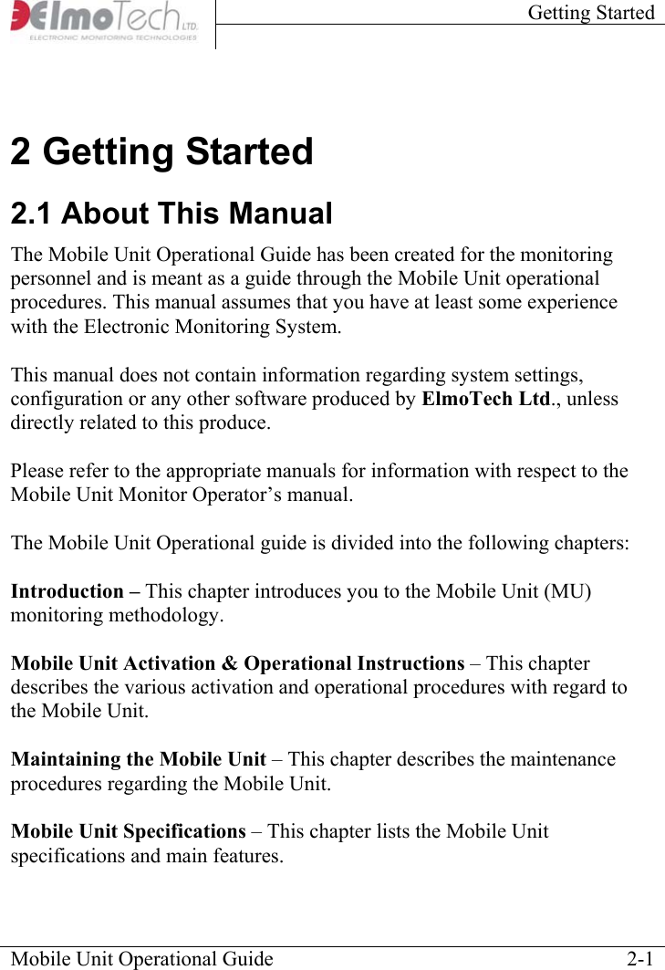
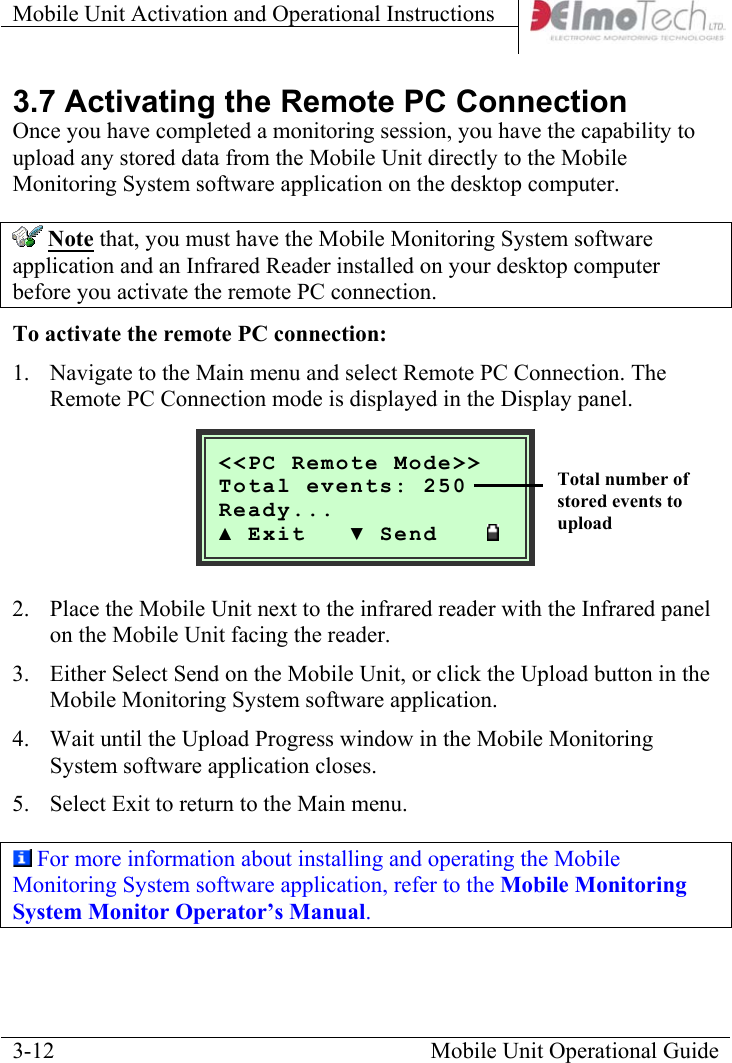
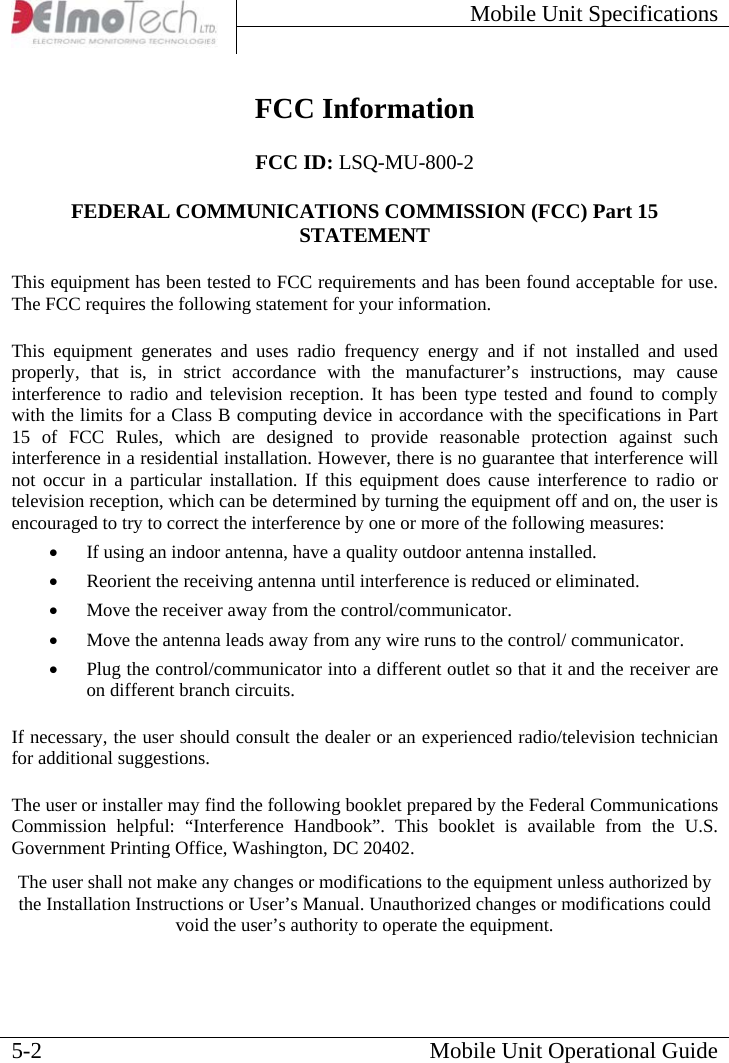
![Mobile Unit Activation and Operational Instructions 3.2 Activating the Mobile Unit To activate the Mobile Unit while in Off mode: Connect one end of the power adapter into the wall socket and connect the other end into the charging socket on the Mobile Unit. To activate the Mobile Unit while in Standby mode: Press the Down V button continuously for about 3 seconds. Once activated the Mobile Unit makes an audible beeping sound, the system logo, version number and current date and time are briefly displayed in the Display panel. The Mobile Unit automatically enters into monitoring mode. This indicates that the Mobile Unit has been activated successfully. To deactivate the Mobile Unit: Select Menu, navigate to the Off menu and select either Standby or Off. Once deactivated, the Mobile Unit shuts down. 3.3 Navigating the Display Panel To enter the Main menu: Select Menu located on the Control bar. The Main menu is displayed. Mobile Unit Operational Guide 3-2 <MNU>[OFF] MEM REM SET ; Shutdown unit ▲ Enter ▼ Next Menu bar Battery level indicator Control bar](https://usermanual.wiki/Attenti/MU-800-2/User-Guide-1004247-Page-10.png)
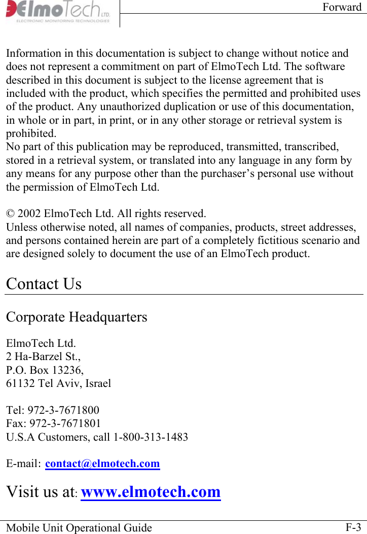
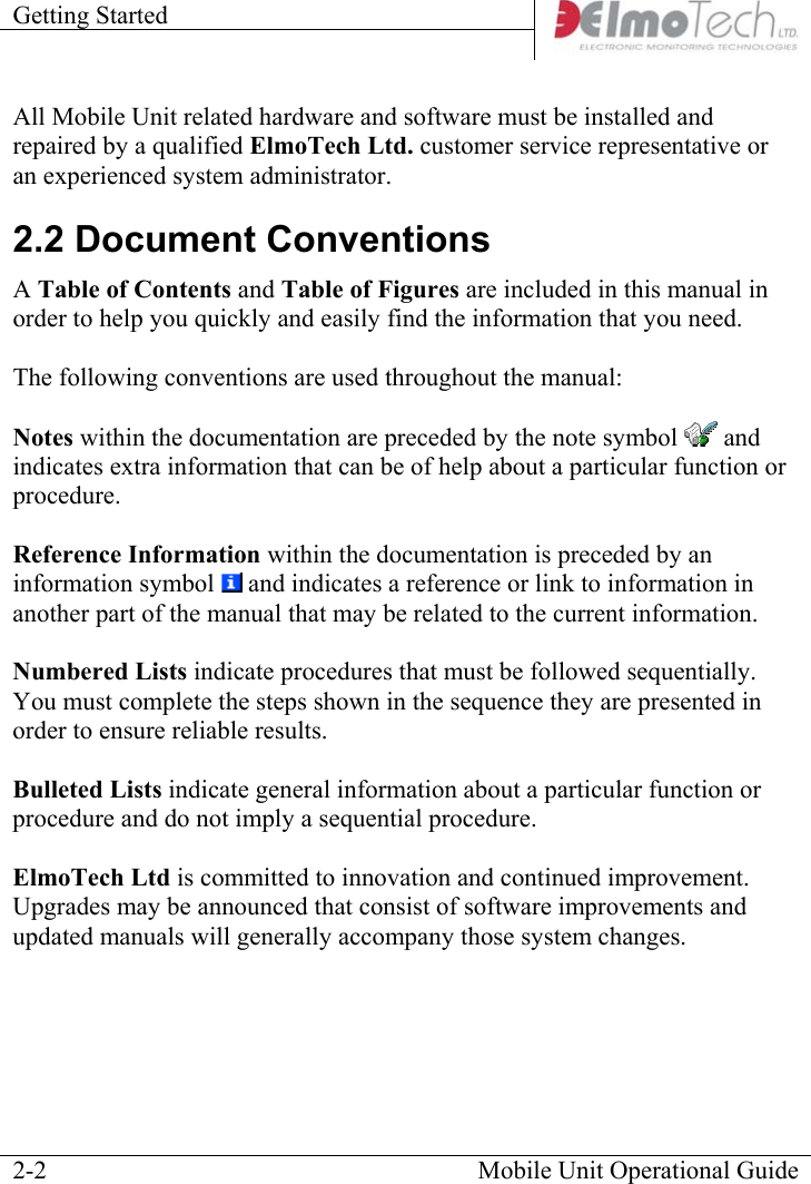
![Mobile Unit Activation and Operational Instructions The Menu bar is located in the upper section of the Display panel and can be used to navigate through the appropriate menu options. The Control bar is located in the lower section of the Display panel and, by using the Up △ and Down ▽ buttons on the Mobile Unit, can be used to navigate through the Main menu and select menu options. Note that, the menu or setting option positioned between the [….] symbols indicates which menu option is currently selected. To navigate through the Main menu: Select Next. Once you have reached the desired menu option, select Enter. To return to the previous menu: Navigate to the Back symbol and then select Enter. To exit a menu: Navigate to the Exit symbol ; and then select Enter. The Battery level indicator is located on the right side of the Display panel next to the Control bar. For information about charging the Mobile Unit, refer to the section about, Charging the Mobile Unit. Mobile Unit Operational Guide 3-3](https://usermanual.wiki/Attenti/MU-800-2/User-Guide-1004247-Page-11.png)
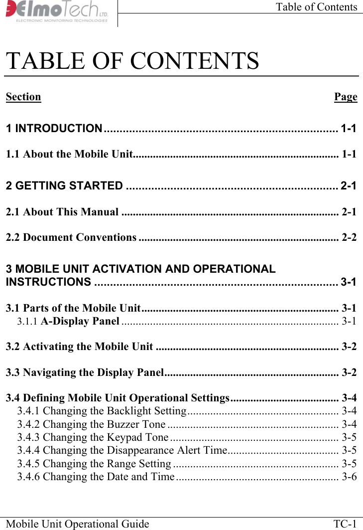
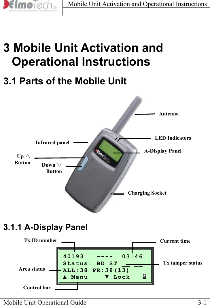
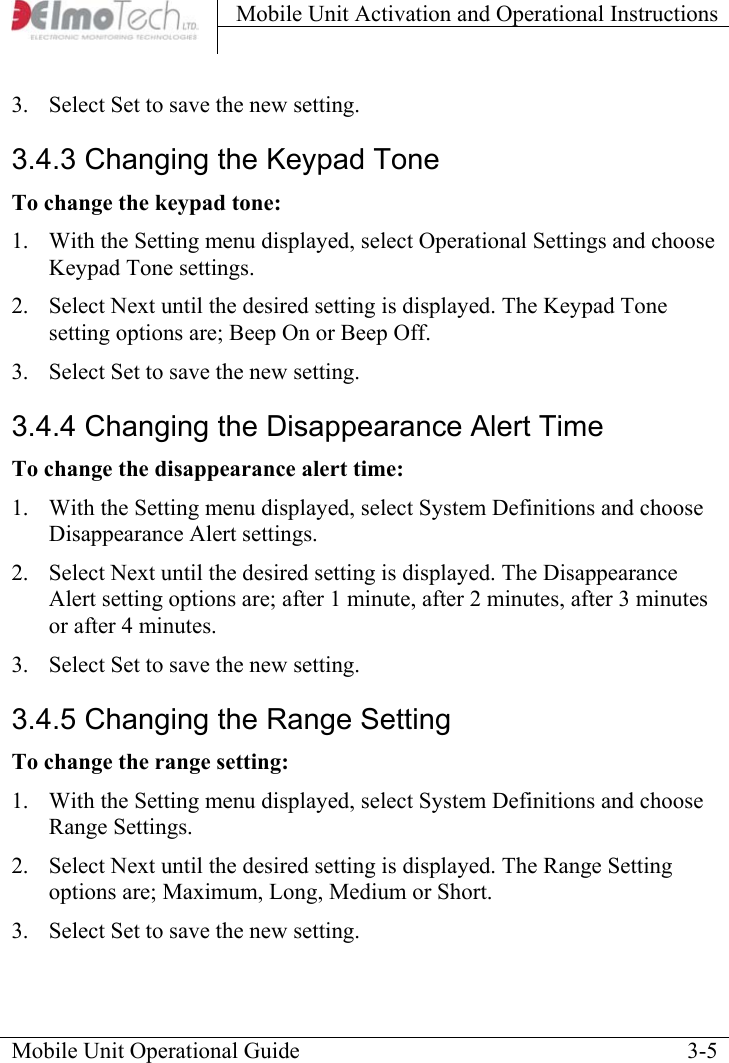
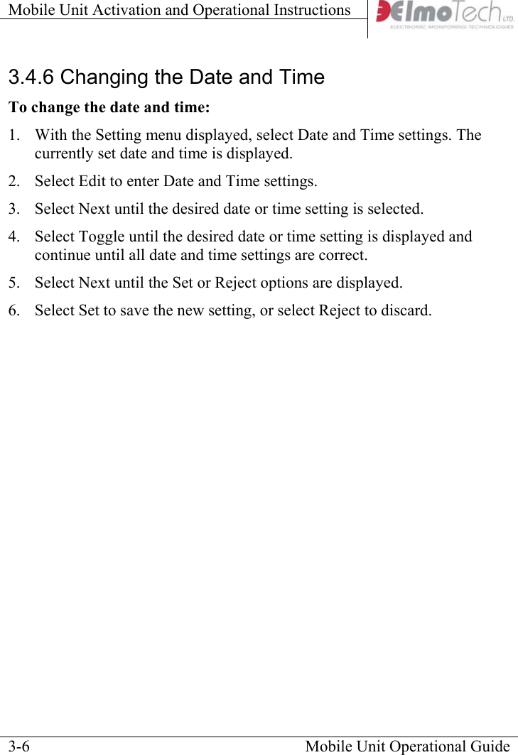
![Mobile Unit Activation and Operational Instructions 3.4 Defining Mobile Unit Operational Settings To enter the Settings menu: Navigate to the Main menu and select Settings. The Settings menu is displayed. Mobile Unit Operational Guide 3-4<SET>[OPR] SYS TIM ;Operational Options▲ Enter ▼ Next 3.4.1 Changing the Backlight Setting To change the backlight settings: 1. With the Setting menu displayed, select Operational Settings and choose Backlight settings. 2. Select Next until the desired setting is displayed. The Backlight setting options are; Always Off, Always On or Auto shutdown after 20 seconds. 3. Select Set to save the new setting. 3.4.2 Changing the Buzzer Tone To change the buzzer tone: 1. With the Setting menu displayed, select Operational Settings and choose Buzzer Tone settings. 2. Select Next until the desired setting is displayed. The Buzzer Tone setting options are; Always Off, Low Volume, Medium Volume or High Volume.](https://usermanual.wiki/Attenti/MU-800-2/User-Guide-1004247-Page-12.png)
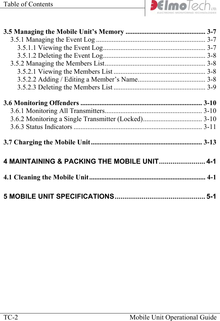
![Mobile Unit Activation and Operational Instructions 3.5 Managing the Mobile Unit’s Memory Before you start a new monitoring session, you have the option to view and / or delete all redundant data previously stored in the Mobile Unit’s memory. To enter to the Memory Management menu: Navigate to the Main menu and select Memory Management. The Memory Management menu is displayed. Mobile Unit Operational Guide 3-7<MEM>[LOG] LST ; Event Logger ▲ Enter ▼ Next 3.5.1 Managing the Event Log To enter the Event Log menu: 1. With the Memory Management menu displayed, select Event Log. 2. Select Next until the desired event log option is displayed. The Event Log options are; View event log or Delete event log. 3.5.1.1 Viewing the Event Log To view the event log: 1. With the Event Log menu displayed, select Next until the View Event Log option is displayed and then select Enter. 2. Select Browse to browse through the event log, or select Exit to return to the Memory Management menu.](https://usermanual.wiki/Attenti/MU-800-2/User-Guide-1004247-Page-15.png)