Attenti MU-800-2 Data receiver User Manual MONITORING WORK STATION
3M Electronic Monitoring, Inc. Data receiver MONITORING WORK STATION
Attenti >
Users Manual

ELECTRONIC MONITORING SYSTEM
MOBILE UNIT OPERATIONAL
GUIDE(
(MU-800-2)

Forward
Mobile Unit Operational Guide
F-3
Information in this documentation is subject to change without notice and
does not represent a commitment on part of ElmoTech Ltd. The software
described in this document is subject to the license agreement that is
included with the product, which specifies the permitted and prohibited uses
of the product. Any unauthorized duplication or use of this documentation,
in whole or in part, in print, or in any other storage or retrieval system is
prohibited.
No part of this publication may be reproduced, transmitted, transcribed,
stored in a retrieval system, or translated into any language in any form by
any means for any purpose other than the purchaser’s personal use without
the permission of ElmoTech Ltd.
© 2002 ElmoTech Ltd. All rights reserved.
Unless otherwise noted, all names of companies, products, street addresses,
and persons contained herein are part of a completely fictitious scenario and
are designed solely to document the use of an ElmoTech product.
Contact Us
Corporate Headquarters
ElmoTech Ltd.
2 Ha-Barzel St.,
P.O. Box 13236,
61132 Tel Aviv, Israel
Tel: 972-3-7671800
Fax: 972-3-7671801
U.S.A Customers, call 1-800-313-1483
E-mail: contact@elmotech.com
Visit us at: www.elmotech.com

Table of Contents
Mobile Unit Operational Guide
TC-1
TABLE OF CONTENTS
Section Page
1 INTRODUCTION.......................................................................... 1-1
1.1 About the Mobile Unit........................................................................ 1-1
2 GETTING STARTED ................................................................... 2-1
2.1 About This Manual ............................................................................ 2-1
2.2 Document Conventions ...................................................................... 2-2
3 MOBILE UNIT ACTIVATION AND OPERATIONAL
INSTRUCTIONS ............................................................................. 3-1
3.1 Parts of the Mobile Unit..................................................................... 3-1
3.1.1 A-Display Panel ............................................................................ 3-1
3.2 Activating the Mobile Unit ................................................................ 3-2
3.3 Navigating the Display Panel............................................................. 3-2
3.4 Defining Mobile Unit Operational Settings...................................... 3-4
3.4.1 Changing the Backlight Setting..................................................... 3-4
3.4.2 Changing the Buzzer Tone ............................................................ 3-4
3.4.3 Changing the Keypad Tone........................................................... 3-5
3.4.4 Changing the Disappearance Alert Time....................................... 3-5
3.4.5 Changing the Range Setting .......................................................... 3-5
3.4.6 Changing the Date and Time......................................................... 3-6

Table of Contents
Mobile Unit Operational Guide
TC-2
3.5 Managing the Mobile Unit’s Memory .............................................. 3-7
3.5.1 Managing the Event Log ............................................................... 3-7
3.5.1.1 Viewing the Event Log........................................................... 3-7
3.5.1.2 Deleting the Event Log........................................................... 3-8
3.5.2 Managing the Members List.......................................................... 3-8
3.5.2.1 Viewing the Members List ..................................................... 3-8
3.5.2.2 Adding / Editing a Member’s Name....................................... 3-8
3.5.2.3 Deleting the Members List ..................................................... 3-9
3.6 Monitoring Offenders ...................................................................... 3-10
3.6.1 Monitoring All Transmitters........................................................ 3-10
3.6.2 Monitoring a Single Transmitter (Locked).................................. 3-10
3.6.3 Status Indicators .......................................................................... 3-11
3.7 Charging the Mobile Unit ................................................................ 3-13
4 MAINTAINING & PACKING THE MOBILE UNIT........................ 4-1
4.1 Cleaning the Mobile Unit................................................................... 4-1
5 MOBILE UNIT SPECIFICATIONS............................................... 5-1

Introduction
Mobile Unit Operational Guide
1-1
1 Introduction
1.1 About the Mobile Unit
The Mobile Unit (MU) is based on Elmo-Tech’s field proven RF
PRQLWRULQJtechnology and is one of the many unique elements of the
(OHFWURQLFMonitoring System.
The Mobile Unit is a lightweight, palm sized, portable monitoring device
that can be used by mobile officers in the field to detect the presence of
clients wearing Elmo-Tech Transmitters.
The Mobile Unit is an add-on module that allows officers to discreetly
confirm offender locations, while avoiding any physical contact as well as
interruptions in offender daily activities. It enables officers to monitor
clients who are required to attend work, school, or counseling sessions,
therefore helping monitoring personnel to verify compliance with schedule
requirements and sentence restrictions.
The Mobile Unit includes the following features:
• Ability to verify monitored offender compliance while patrolling in a
vehicle, or on foot
• Minimizing direct unnecessary contact with offenders
• Light, palm sized and water-resistant new design
• 18 hour rechargeable battery
• Extended memory capacity
• Windows™ PC interface, for batch report processing

Getting Started
Mobile Unit Operational Guide
2-1
2 Getting Started
2.1 About This Manual
The Mobile Unit Operational Guide has been created for the monitoring
personnel and is meant as a guide through the Mobile Unit operational
procedures. This manual assumes that you have at least some experience
with the Electronic Monitoring System.
This manual does not contain information regarding system settings,
configuration or any other software produced by ElmoTech Ltd., unless
directly related to this produce.
Please refer to the appropriate manuals for information with respect to the
Mobile Unit Monitor Operator’s manual.
The Mobile Unit Operational guide is divided into the following chapters:
Introduction – This chapter introduces you to the Mobile Unit (MU)
monitoring methodology.
Mobile Unit Activation & Operational Instructions – This chapter
describes the various activation and operational procedures with regard to
the Mobile Unit.
Maintaining the Mobile Unit – This chapter describes the maintenance
procedures regarding the Mobile Unit.
Mobile Unit Specifications – This chapter lists the Mobile Unit
specifications and main features.

Getting Started
All Mobile Unit related hardware and software must be installed and
repaired by a qualified ElmoTech Ltd. customer service representative or
an experienced system administrator.
2.2 Document Conventions
A Table of Contents and Table of Figures are included in this manual in
order to help you quickly and easily find the information that you need.
The following conventions are used throughout the manual:
Notes within the documentation are preceded by the note symbol and
indicates extra information that can be of help about a particular function or
procedure.
Reference Information within the documentation is preceded by an
information symbol and indicates a reference or link to information in
another part of the manual that may be related to the current information.
Numbered Lists indicate procedures that must be followed sequentially.
You must complete the steps shown in the sequence they are presented in
order to ensure reliable results.
Bulleted Lists indicate general information about a particular function or
procedure and do not imply a sequential procedure.
ElmoTech Ltd is committed to innovation and continued improvement.
Upgrades may be announced that consist of software improvements and
updated manuals will generally accompany those system changes.
Mobile Unit Operational Guide
2-2
Mobile Unit Activation and Operational Instructions
3 Mobile Unit Activation and
Operational Instructions
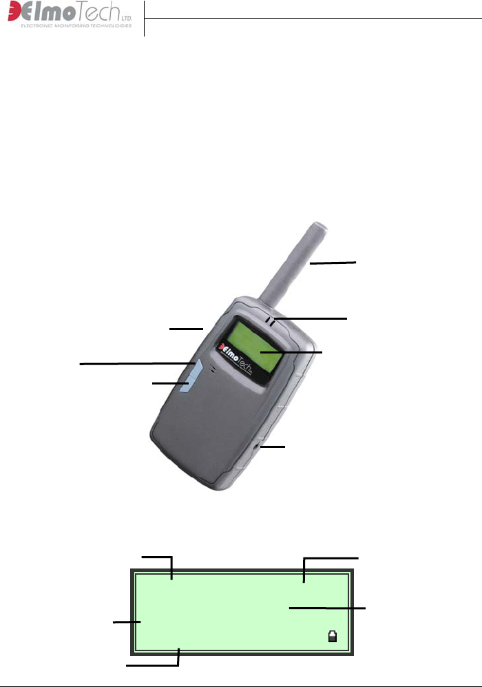
3.1 Parts of the Mobile Unit
Antenna
LED Indicators
Infrared panel
A-Display Panel
Up U
Button Down V
Button
Charging Socket
3.1.1 A-Display Panel
Mobile Unit Operational Guide
3-1
40193 ---- 03:46
__ Status: BD ST __
A
LL:38 PR:38(13)
▲ Menu ▼ Lock
Tx ID number Current time
Tx tamper status
Area status
Control bar
Mobile Unit Activation and Operational Instructions
3.2 Activating the Mobile Unit
To activate the Mobile Unit while in Off mode:
Connect one end of the power adapter into the wall socket and connect the
other end into the charging socket on the Mobile Unit.
To activate the Mobile Unit while in Standby mode:
Press the Down V button continuously for about 3 seconds. Once activated
the Mobile Unit makes an audible beeping sound, the system logo, version
number and current date and time are briefly displayed in the Display panel.
The Mobile Unit automatically enters into monitoring mode. This indicates
that the Mobile Unit has been activated successfully.
To deactivate the Mobile Unit:
Select Menu, navigate to the Off menu and select either Standby or Off.
Once deactivated, the Mobile Unit shuts down.
3.3 Navigating the Display Panel
To enter the Main menu:
Select Menu located on the Control bar. The Main menu is displayed.
Mobile Unit Operational Guide
3-2
<
MNU>[OFF] MEM REM
SET ;
Shutdown unit
▲ Enter ▼ Next
Menu bar
Battery level
indicator
Control bar
Mobile Unit Activation and Operational Instructions
The Menu bar is located in the upper section of the Display panel and can be
used to navigate through the appropriate menu options.
The Control bar is located in the lower section of the Display panel and, by
using the Up △ and Down ▽ buttons on the Mobile Unit, can be used to
navigate through the Main menu and select menu options.
Note that, the menu or setting option positioned between the [….]
symbols indicates which menu option is currently selected.
To navigate through the Main menu:
Select Next. Once you have reached the desired menu option, select Enter.
To return to the previous menu:
Navigate to the Back symbol and then select Enter.
To exit a menu:
Navigate to the Exit symbol ; and then select Enter.
The Battery level indicator is located on the right side of the Display panel
next to the Control bar.
For information about charging the Mobile Unit, refer to the section
about, Charging the Mobile Unit.
Mobile Unit Operational Guide
3-3

Mobile Unit Activation and Operational Instructions
3.4 Defining Mobile Unit Operational
Settings
To enter the Settings menu:
Navigate to the Main menu and select Settings. The Settings menu is
displayed.
Mobile Unit Operational Guide
3-4
<
SET>[OPR] SYS TIM
;
Operational Options
▲ Enter ▼ Next
3.4.1 Changing the Backlight Setting
To change the backlight settings:
1. With the Setting menu displayed, select Operational Settings and choose
Backlight settings.
2. Select Next until the desired setting is displayed. The Backlight setting
options are; Always Off, Always On or Auto shutdown after 20 seconds.
3. Select Set to save the new setting.
3.4.2 Changing the Buzzer Tone
To change the buzzer tone:
1. With the Setting menu displayed, select Operational Settings and choose
Buzzer Tone settings.
2. Select Next until the desired setting is displayed. The Buzzer Tone
setting options are; Always Off, Low Volume, Medium Volume or High
Volume.

Mobile Unit Activation and Operational Instructions
Mobile Unit Operational Guide
3-5
3. Select Set to save the new setting.
3.4.3 Changing the Keypad Tone
To change the keypad tone:
1. With the Setting menu displayed, select Operational Settings and choose
Keypad Tone settings.
2. Select Next until the desired setting is displayed. The Keypad Tone
setting options are; Beep On or Beep Off.
3. Select Set to save the new setting.
3.4.4 Changing the Disappearance Alert Time
To change the disappearance alert time:
1. With the Setting menu displayed, select System Definitions and choose
Disappearance Alert settings.
2. Select Next until the desired setting is displayed. The Disappearance
Alert setting options are; after 1 minute, after 2 minutes, after 3 minutes
or after 4 minutes.
3. Select Set to save the new setting.
3.4.5 Changing the Range Setting
To change the range setting:
1. With the Setting menu displayed, select System Definitions and choose
Range Settings.
2. Select Next until the desired setting is displayed. The Range Setting
options are; Maximum, Long, Medium or Short.
3. Select Set to save the new setting.

Mobile Unit Activation and Operational Instructions
Mobile Unit Operational Guide
3-6
3.4.6 Changing the Date and Time
To change the date and time:
1. With the Setting menu displayed, select Date and Time settings. The
currently set date and time is displayed.
2. Select Edit to enter Date and Time settings.
3. Select Next until the desired date or time setting is selected.
4. Select Toggle until the desired date or time setting is displayed and
continue until all date and time settings are correct.
5. Select Next until the Set or Reject options are displayed.
6. Select Set to save the new setting, or select Reject to discard.

Mobile Unit Activation and Operational Instructions
3.5 Managing the Mobile Unit’s Memory
Before you start a new monitoring session, you have the option to view and /
or delete all redundant data previously stored in the Mobile Unit’s memory.
To enter to the Memory Management menu:
Navigate to the Main menu and select Memory Management. The Memory
Management menu is displayed.
Mobile Unit Operational Guide
3-7
<
MEM>[LOG] LST
;
Event Logger
▲ Enter ▼ Next
3.5.1 Managing the Event Log
To enter the Event Log menu:
1. With the Memory Management menu displayed, select Event Log.
2. Select Next until the desired event log option is displayed. The Event
Log options are; View event log or Delete event log.
3.5.1.1 Viewing the Event Log
To view the event log:
1. With the Event Log menu displayed, select Next until the View Event
Log option is displayed and then select Enter.
2. Select Browse to browse through the event log, or select Exit to return to
the Memory Management menu.

Mobile Unit Activation and Operational Instructions
Mobile Unit Operational Guide
3-8
3.5.1.2 Deleting the Event Log
To delete the event log:
1. With the Event Log menu displayed, select Next until the Delete Event
Log option is displayed and then select Enter.
2. Select Yes to confirm the deletion, or select No to return to the Memory
Management menu.
3.5.2 Managing the Members List
To enter the Member List menu:
1. With the Memory Management menu displayed, select Member List.
2. Select Next until the desired member list option is displayed. The
Member List options are; View all members or Delete all members.
3.5.2.1 Viewing the Members List
To view the member list:
1. With the Member List menu displayed, select Next until the View all
members option is displayed and then select Enter.
2. Select Next to browse the members list, or select Exit to return to the
Memory Management menu.
3.5.2.2 Adding / Editing a Member’s Name
To add / edit a member’s name:
1. With the Member List menu displayed, select Next until the View all
members option is displayed and then select Enter.
2. Select Next until the desired member is displayed and the select Edit.
3. Select Next until the Edit Name option is displayed and then select
Enter.

Mobile Unit Activation and Operational Instructions
Mobile Unit Operational Guide
3-9
4. Select Toggle until the desired letter is displayed and then select Next to
move onto the next letter.
5. Repeat this process until the members name has been entered into the
Name field.
6. Select Next until the Set or Reject options are displayed.
7. Select Set to save or Reject to cancel
3.5.2.3 Deleting the Members List
To delete the member list:
1. With the Member List menu displayed, select Next until the Delete all
members’ option is displayed and then select Enter.
2. Select Yes to confirm the deletion, or select No to return to the Memory
Management menu.
Mobile Unit Activation and Operational Instructions
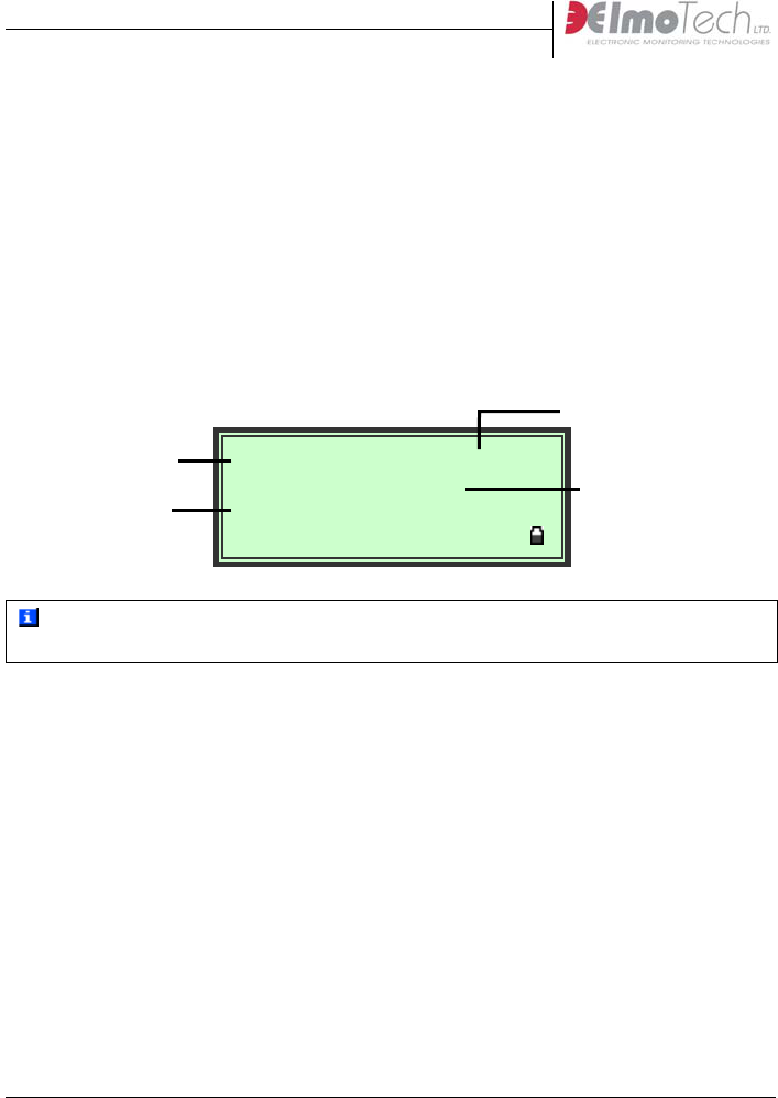
3.6 Monitoring Offenders
You can use the Mobile Unit to monitor the continuously changing status of
all Transmitters currently present within the defined range of the Mobile
Unit, or you can lock onto and search for a single Transmitter.
3.6.1 Monitoring All Transmitters
Once the Mobile Unit has been activated the unit automatically enters into
monitoring mode.
Mobile Unit Operational Guide
3-10
40193 ---- 03:46
__ Status: BD ST __
A
LL:38 PR:38(13)
▲ Menu ▼ Lock
Current time
Tx ID number
Tx tamper status
Area Status
For more information about the Tx tamper status indicators displayed in
the Display panel, refer to the section about, Status Indicators.
3.6.2 Monitoring a Single Transmitter (Locked)
To lock onto an Offender’s Transmitter:
1. With the Mobile Unit in monitoring mode, wait for the desired
Transmitter to be displayed in the Display panel.
Mobile Unit Activation and Operational Instructions
2. Once the desired Transmitter ID is displayed, select Lock. The Mobile
Unit locks onto the selected Transmitter and a visual tracking gauge is
added to the Display panel
Mobile Unit Operational Guide
3-11
40193 ---- 03:46
Status: BD ST __ __
Lock Med ( )
▲ Menu ▼ Unlock
❚❚❚❚❚❚
Tracking gauge
You can use the displayed visual tracking gauge to estimate the approximate
distance between the Mobile Unit and the selected Offender’s Transmitter.
Note that, the longer the visual tracking gauge extends (e.g. ❚ ❚ ❚ ❚ ❚ ❚ ❚ ❚ ❚)
the closer the Mobile Unit is to the selected Transmitter.
To un-lock the Offender’s Transmitter:
Select Unlock.
3.6.3 Status Indicators
A list of the possible status indicators displayed in the Mobile Unit’s display
panel during monitoring are included below:
BD - indicates a Tx body tamper
ST - indicates a Tx strap tamper
RS - indicates that the Tx reset bit is On (valid 24 hour post MRD reset)
BT - indicates a Tx low battery
Mobile Unit Activation and Operational Instructions
3.7 Activating the Remote PC Connection
Once you have completed a monitoring session, you have the capability to
upload any stored data from the Mobile Unit directly to the Mobile
Monitoring System software application on the desktop computer.
Note that, you must have the Mobile Monitoring System software
application and an Infrared Reader installed on your desktop computer
before you activate the remote PC connection.
To activate the remote PC connection:
1. Navigate to the Main menu and select Remote PC Connection. The
Remote PC Connection mode is displayed in the Display panel.
Mobile Unit Operational Guide
3-12
<
<PC Remote Mode>>
nts: 250
Total eve
Ready...
▲ Exit ▼ Send
2. Place the Mobile Unit next to the infrared reader with the Infrared panel
on the Mobile Unit facing the reader.
3. Either Select Send on the Mobile Unit, or click the Upload button in the
Mobile Monitoring System software application.
4. Wait until the Upload Progress window in the Mobile Monitoring
System software application closes.
5. Select Exit to return to the Main menu.
For more information about installing and operating the Mobile
Monitoring System software application, refer to the Mobile Monitoring
System Monitor Operator’s Manual.
Total number of
stored events to
upload
Mobile Unit Activation and Operational Instructions
3.8 Charging the Mobile Unit
In order to keep the Mobile Unit fully operational, you should connect the
unit to the supplied charging adapter whenever the unit is not in immediate
use.
To charge the Mobile Unit:
1. Connect the appropriate end of the supplied charging adapter into either,
the wall power socket, or the vehicle’s cigarette lighter power outlet.
2. Connect the small end of the charging adapter into the charging socket
located on the Mobile Unit. The left LED indicator lights up indicating
the Mobile Unit is in charging mode.
Note that, if the Mobile Unit is connected for charging while the actual
unit is in Off mode, the unit automatically activates itself and charging
commences.
NOTICE - In case of the following:
■ The LCD indicator blinks irregularly
■ The unit unpredictably turns off and resets itself
■ Any other irregular actions
Please disconnect and turn off, and return it to the monitoring agency /
supplier for replacement. Do not attempt to fix the unit by yourself.
For agencies / customers: Do not use faulty units at any time. If any of the
above malfunctions occur, return the unit to ElmoTech for repair.
Mobile Unit Operational Guide
3-13

Maintaining & Packing the Mobile Unit
4 Maintaining & Packing the Mobile
Unit
4.1 Cleaning the Mobile Unit
To clean the Mobile unit:
1. Remove the Mobile Unit from its water resistant carrying pouch and
simply wipe the outside of the unit with a damp cloth.
Do not, under any circumstances, submerge or place the Mobile
unit under running water.
2. Using a piece of cloth or a paper towel, dry the outer side of the Mobile
Unit.
3. Once the Mobile Unit is dry, place the unit into the water resistant pouch
and then into the specially designed transportation case.
Mobile Unit Operational Guide
4-1

Mobile Unit Specifications
Mobile Unit Operational Guide
5-1
5 Mobile Unit Specifications
Mobile Unit Features
• Light, palm sized and water-
resistant new design
• Ability to verify monitored
offender compliance while
patrolling in a vehicle, or on
foot
• Minimizing direct
unnecessary contact with
offenders
• Extended memory capacity
• Windows™ PC interface, for
batch report processing
Memory
• Store and monitor up to 200
transmitters
• Log up to 3000 events
• Records are time stamped
Operating Characteristics
• Battery Life between charges:
16-24 hours
• Charge Time: 5 hours
Mechanical Characteristics
• Water Resistant
• Size: 14 x 8.5 x 3.5 cm (5.5 x
3.3 x 1.4 in)
• Antenna length:11 cm (4.1 in)
• LCD message display
• Backlight push button
• Acknowledge push button
• Waterproof pouch with belt
clip

Mobile Unit Specifications
Mobile Unit Operational Guide
5-2
FCC Information
FCC ID: LSQ-MU-800-2
FEDERAL COMMUNICATIONS COMMISSION (FCC) Part 15
STATEMENT
This equipment has been tested to FCC requirements and has been found acceptable for use.
The FCC requires the following statement for your information.
This equipment generates and uses radio frequency energy and if not installed and used
properly, that is, in strict accordance with the manufacturer’s instructions, may cause
interference to radio and television reception. It has been type tested and found to comply
with the limits for a Class B computing device in accordance with the specifications in Part
15 of FCC Rules, which are designed to provide reasonable protection against such
interference in a residential installation. However, there is no guarantee that interference will
not occur in a particular installation. If this equipment does cause interference to radio or
television reception, which can be determined by turning the equipment off and on, the user is
encouraged to try to correct the interference by one or more of the following measures:
• If using an indoor antenna, have a quality outdoor antenna installed.
• Reorient the receiving antenna until interference is reduced or eliminated.
• Move the receiver away from the control/communicator.
• Move the antenna leads away from any wire runs to the control/ communicator.
• Plug the control/communicator into a different outlet so that it and the receiver are
on different branch circuits.
If necessary, the user should consult the dealer or an experienced radio/television technician
for additional suggestions.
The user or installer may find the following booklet prepared by the Federal Communications
Commission helpful: “Interference Handbook”. This booklet is available from the U.S.
Government Printing Office, Washington, DC 20402.
The user shall not make any changes or modifications to the equipment unless authorized by
the Installation Instructions or User’s Manual. Unauthorized changes or modifications could
void the user’s authority to operate the equipment.