Attenti TD4I-433 433 MHz Tracking Device User Manual Users guide
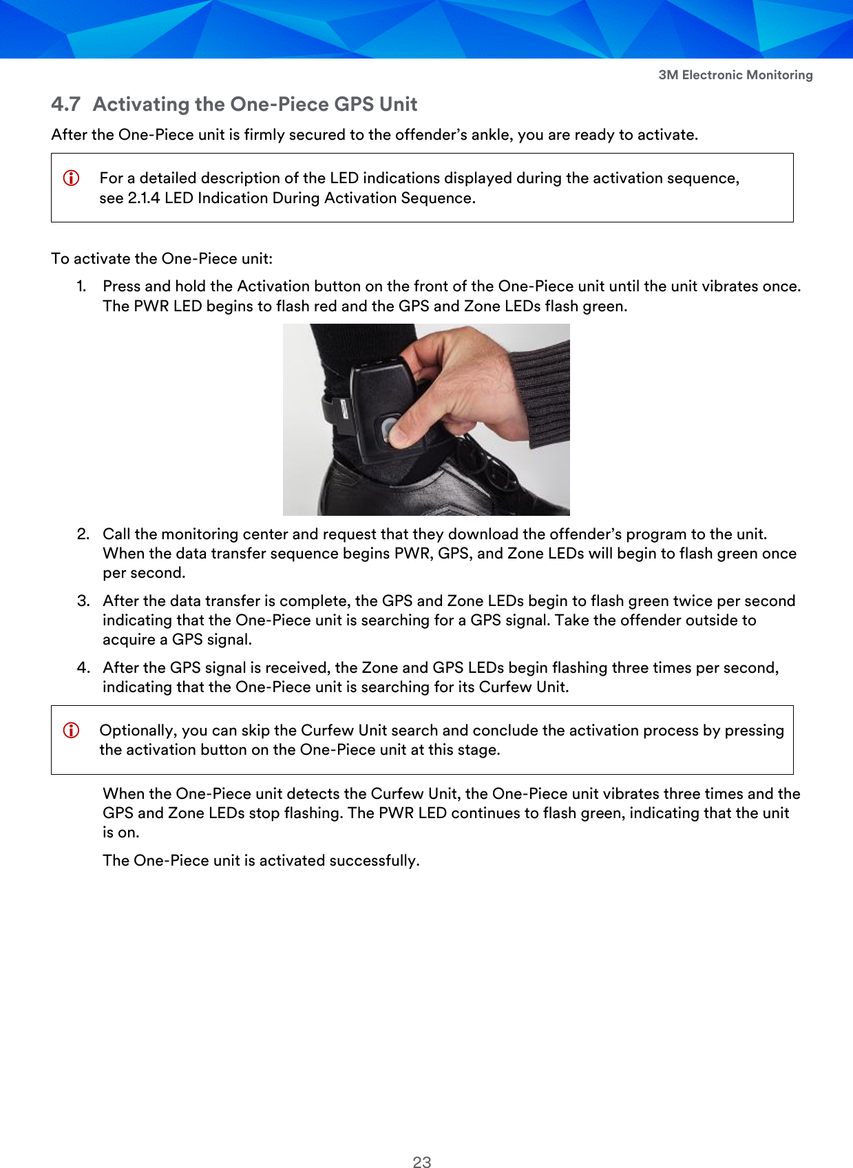
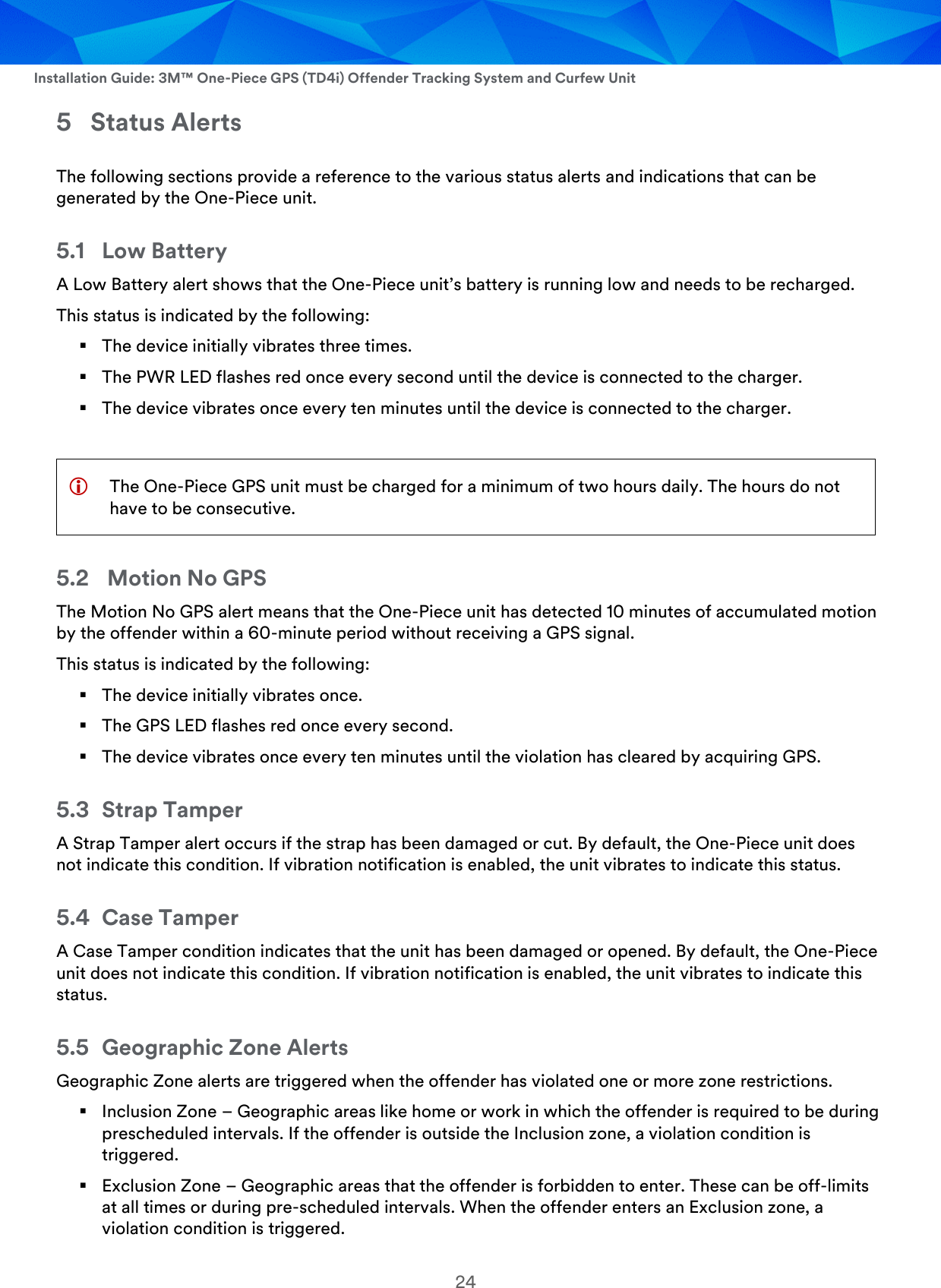
3M Electronic Monitoring, Inc. 433 MHz Tracking Device Users guide
UserManual.wiki
>
Attenti
>
TD4I 433 User Manual
Users guide
Navigation menu
Upload a User Manual
Namespaces
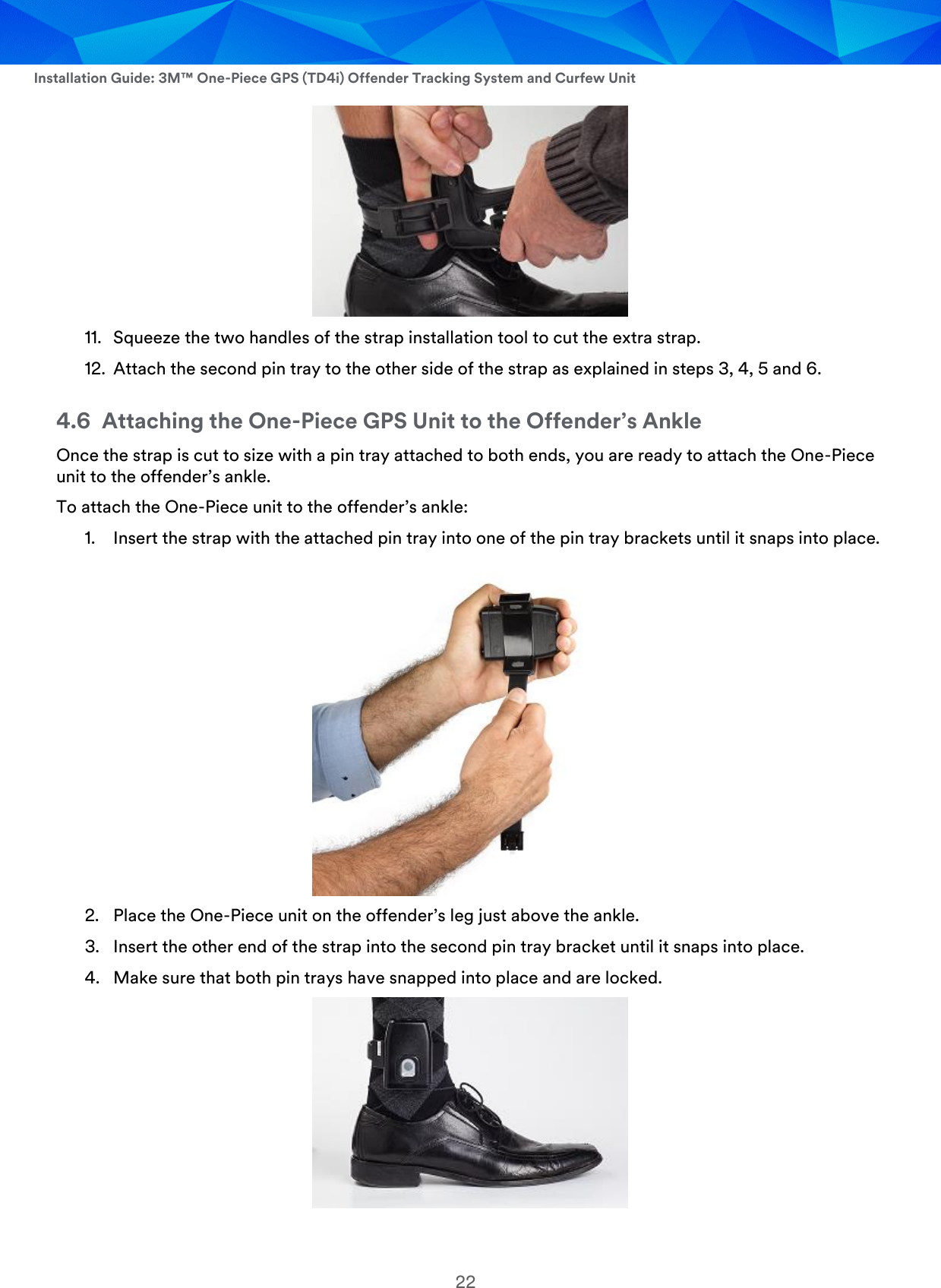
Wiki Guide
HTML
PDF
Info
Views
User Manual
Discussion / Help
Navigation