Attenti TRXS-890-2 RF Transceiver User Manual
Attenti RF Transceiver Users Manual
UserManual.wiki
>
Attenti
>
TRXS 890 2 User Manual
Users Manual
Navigation menu
Upload a User Manual
Namespaces
Wiki Guide
HTML
PDF
Info
Views
User Manual
Discussion / Help
Navigation
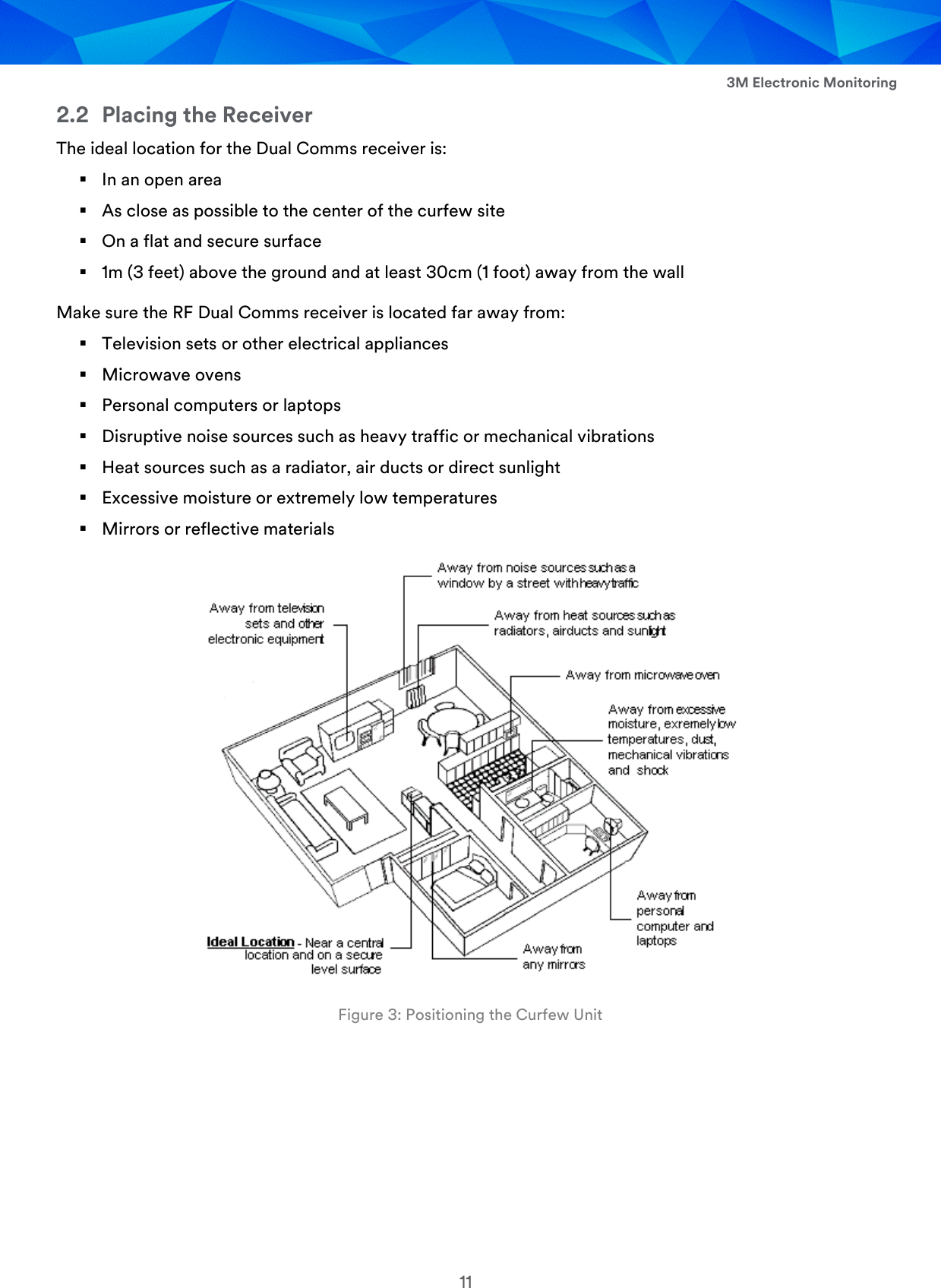
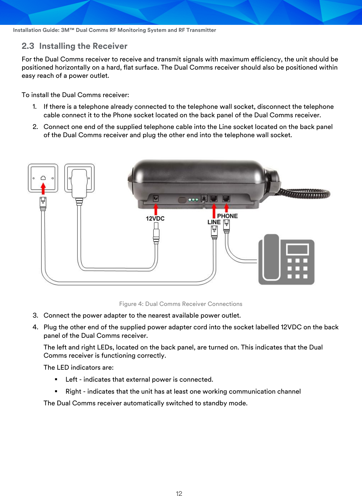
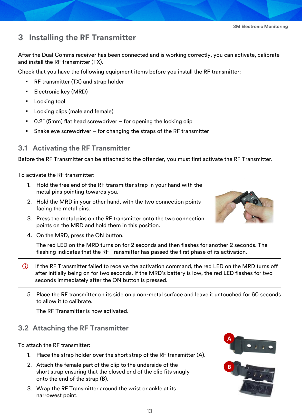
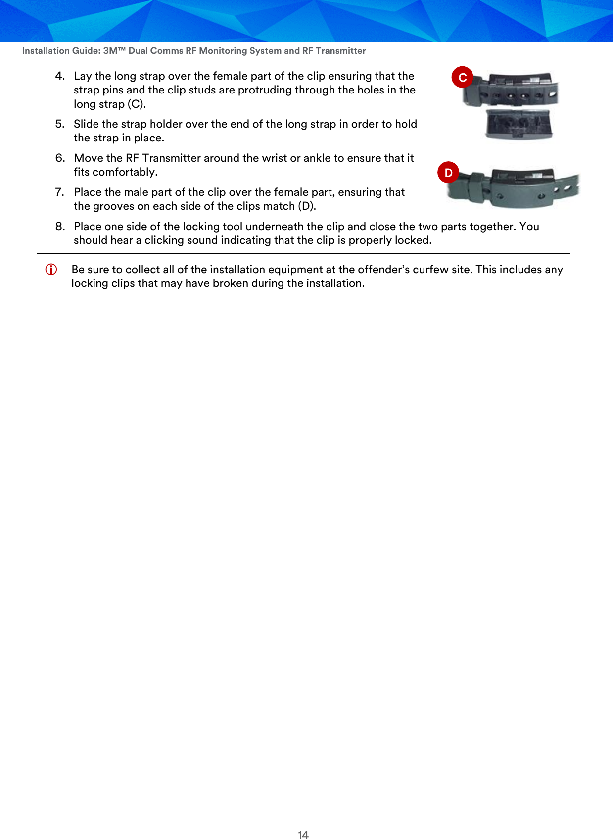
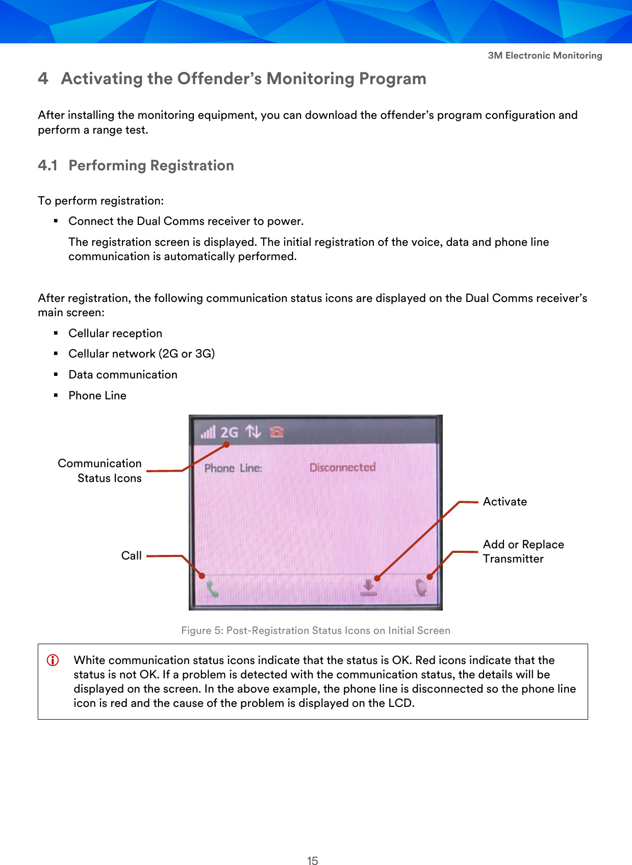
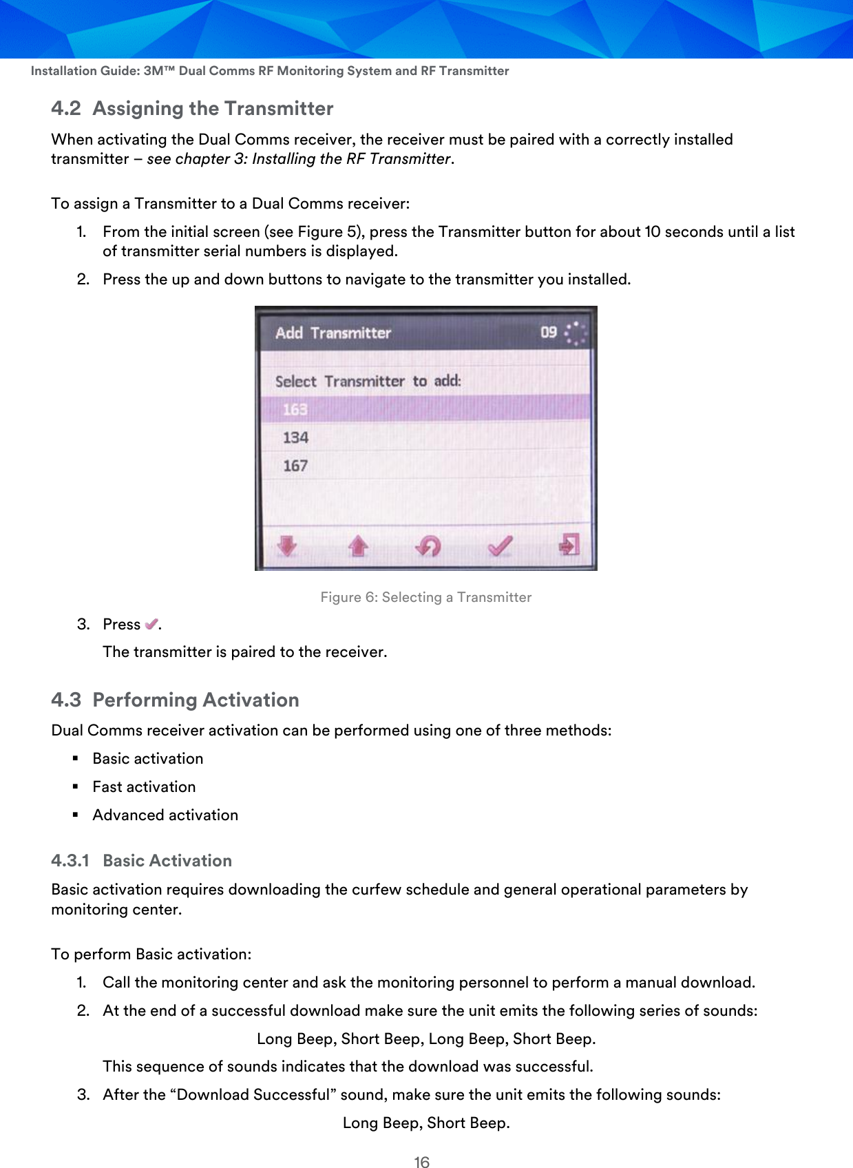
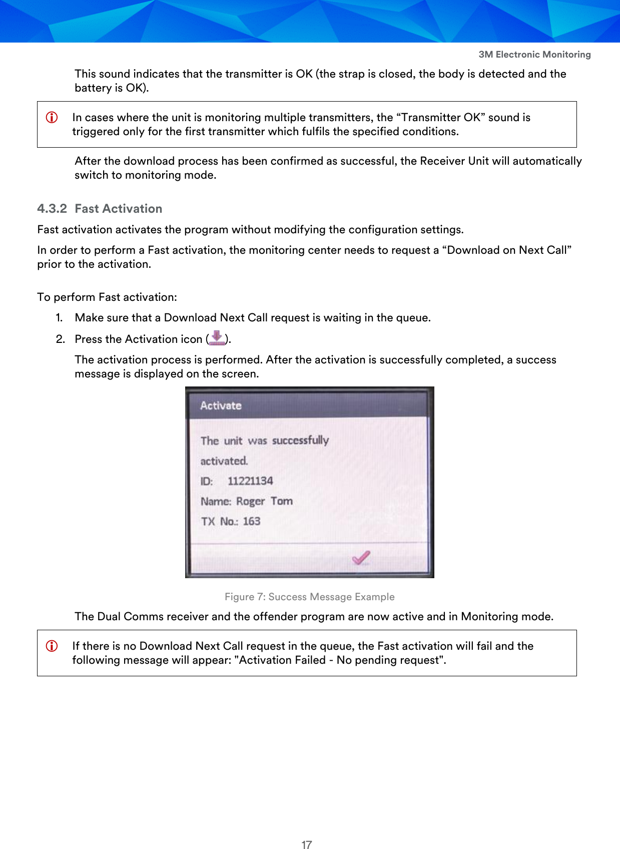
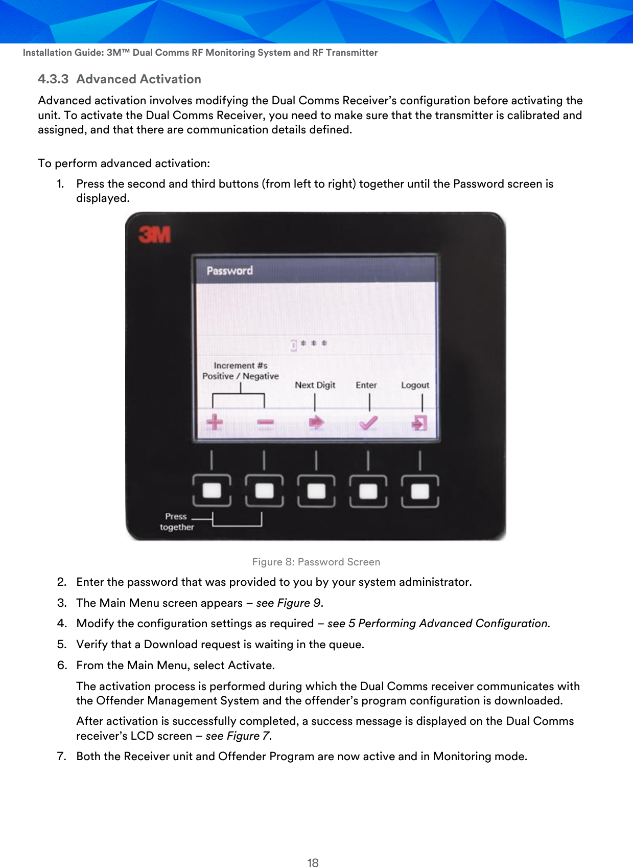
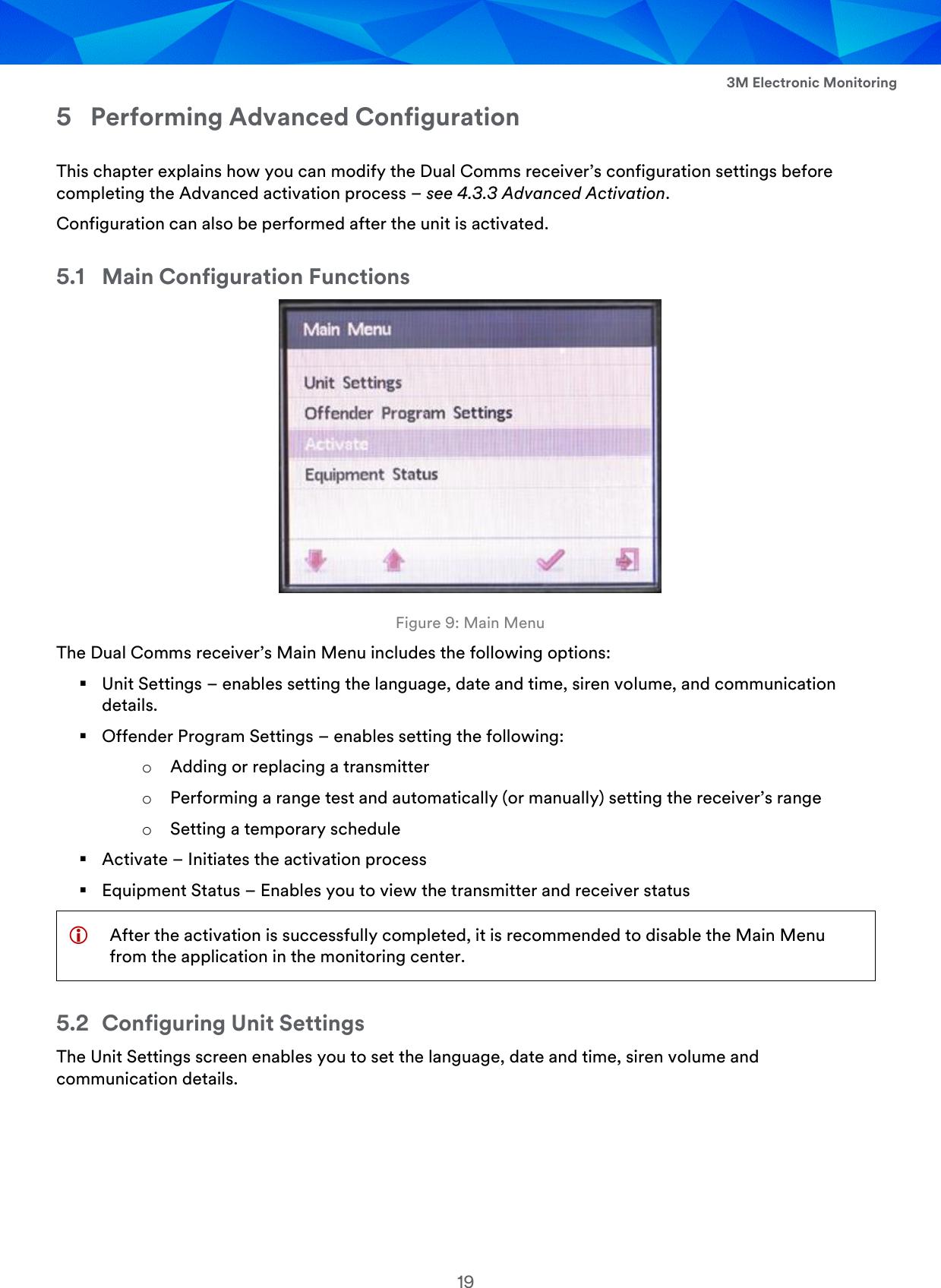
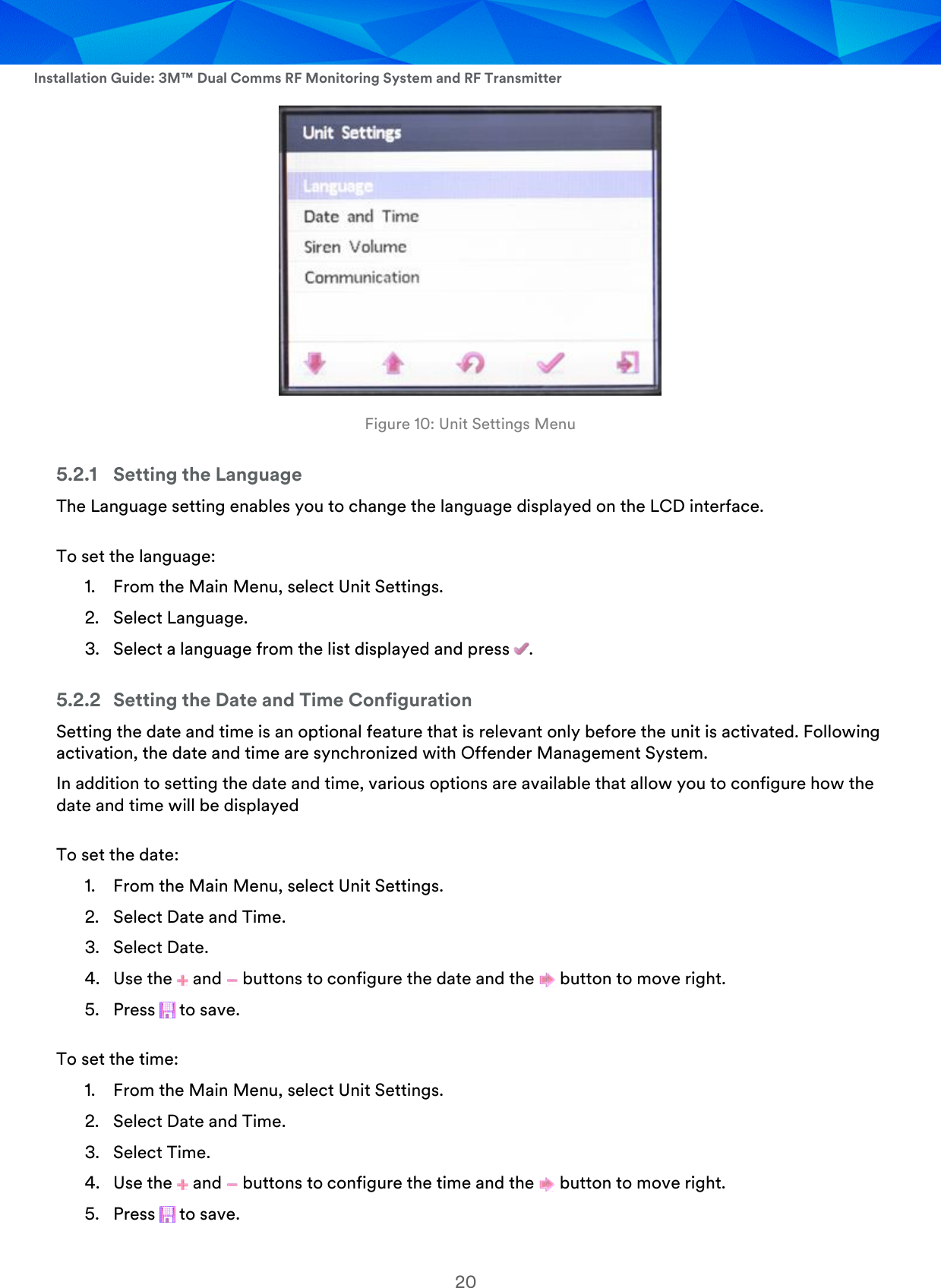
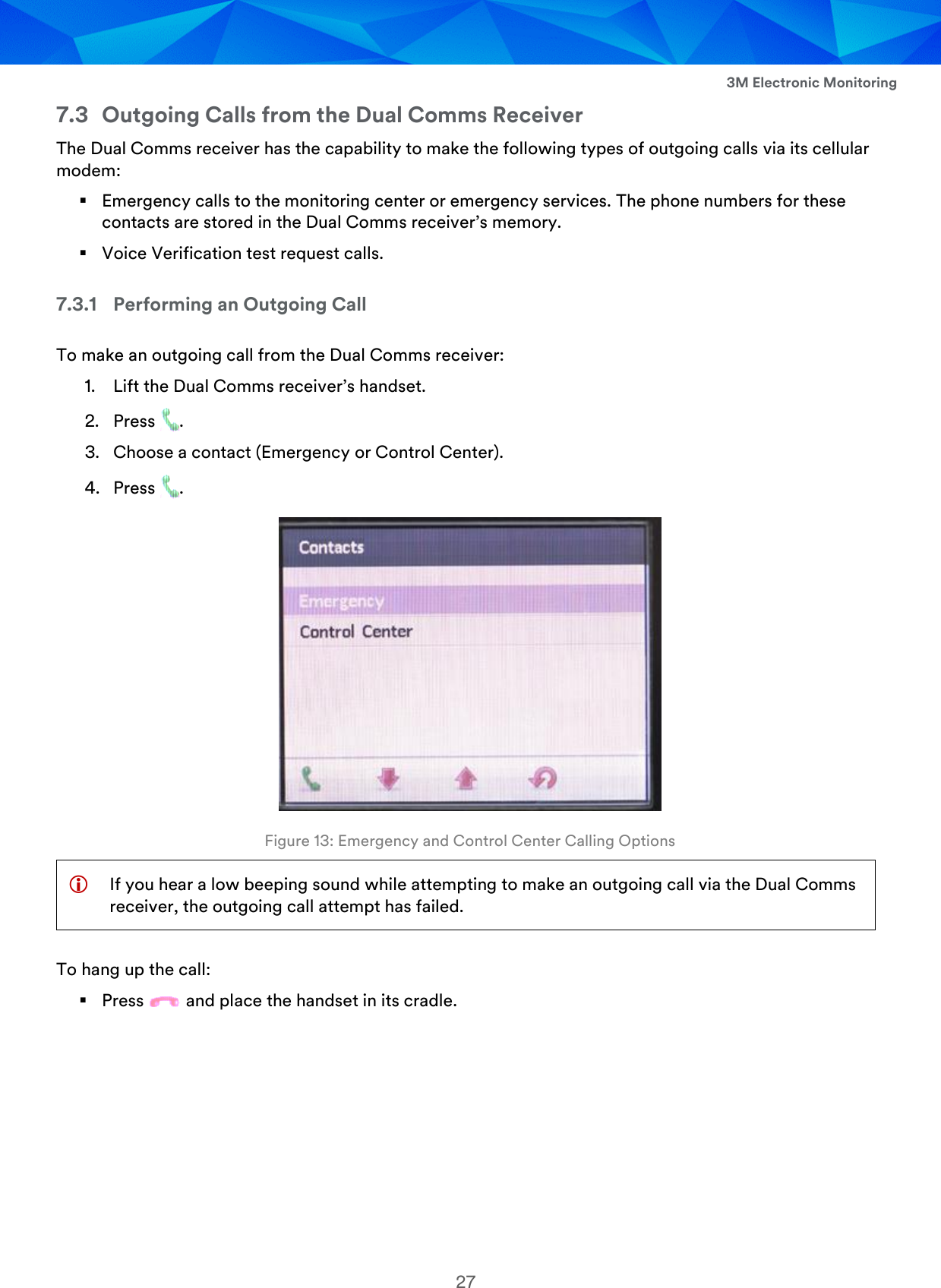
![Installation Guide: 3M™ Dual Comms RF Monitoring System and RF Transmitter 22 5.3 Defining the Communication Details The Communication Details are the telephone numbers, IP and port of the Offender Management System’s communication gateway. To set the communication details: 1. From the Main Menu, select Unit Settings. 2. Select Communication. 3. Enter the following parameters: Landline Number Cellular Number IP Address Port Number 4. Press to save. 5.4 Adding or Replacing a Transmitter After the Dual Comms receiver is activated, it is possible to add or replace transmitters. To add a new transmitter or replace the existing transmitter: 1. From the Main Menu, select Offender Program Settings. 2. Select Transmitter. 3. Select Add Transmitter to add a new transmitter or Replace Transmitter to replace an existing one. A list of serial numbers of transmitters in range of the Dual Comms receiver is displayed. 4. Press the up and down buttons to navigate to the transmitter you want to add. Figure 11: Selecting a Transmitter 5. Press . If you chose to replace a transmitter, the message “The unit is monitoring transmitter number [XXX]. Do you want to replace it?” is displayed. Press to confirm transmitter replacement.](https://usermanual.wiki/Attenti/TRXS-890-2/User-Guide-3731108-Page-22.png)