Users Manual

3M™ Dual Comms RF
Monitoring System and
RF Transmitter
Installation & Operation
February 2017
Installation Guide 3M Electronic Monitoring

Installation Guide: 3M™ Dual Comms RF Monitoring System and RF Transmitter
2
Information in this documentation is subject to change without notice and does not represent a commitment on part of 3M™
Electronic Monitoring. The software described in this document is subject to the license agreement that is included with the
product, which specifies the permitted and prohibited uses of the product.
Any unauthorized duplication or use of this documentation, in whole or in part, in print, or in any other storage or retrieval system
is prohibited. No part of this publication may be reproduced, transmitted, transcribed, stored in a retrieval system, or translated
into any language in any form by any means for any purpose other than the purchaser’s personal use without the permission of
3M™ Electronic Monitoring.
© 1995-2017 3M™ Electronic Monitoring. All rights reserved.
Unless otherwise noted, all names of companies, products, street addresses, and persons contained herein are part of a
completely fictitious scenario and are designed solely to document the use of a 3M™ Electronic Monitoring product.
Contact Us
Corporate Headquarters
3M™ Electronic Monitoring
2 Ha-Barzel St.,
P.O. Box 13236,
61132 Tel Aviv, Israel
Tel: 972-3-7671800
Fax: 972-3-7671801
U.S.A Customers, call 1-800-313-1483
Visit us at: www.3m.com/electronicmonitoring

3M Electronic Monitoring
3
Versions and Changes Table
Version
Status/Changes
Author
Date
1.0
New format – initial release version
Steve Graniewitz
02-FEB-2017
2.0
Addition of TRXS-890 transmitter to Safety Instructions.
Addition of FCC statement.
Steve Graniewitz
06-NOV-2017
Installation Guide: 3M™ Dual Comms RF Monitoring System and RF Transmitter
4
Safety Information
Please read, understand, and follow all safety information contained in these instructions prior to the use of this 3M
Electronic Monitoring device. Retain these instructions for future reference.
Intended Use
This 3M Electronic Monitoring device is part of an electronic monitoring system, which performs data transfer using
the PSTN or cellular network to a monitoring platform. This device has not been tested for and is not intended for
use on airplanes, in hazardous environments, in healthcare facilities, or where cellular phones or other intentional
transmitters are restricted.
The Dual Comms Monitoring Receiver is intended for indoor use only. The operating temperature of the Dual
Comms Monitoring Receiver is -20°C to +55°C. The operating temperature of the TRXS-860 RF Transmitter and
TRXS-890 RF Transmitter is -25°C to +55°C. The storage temperature of the Dual Comms Monitoring Receiver is
-40°C to +55°C. The storage temperature of the TRXS-860 RF Transmitter and TRXS-890 RF Transmitter is -
40°C to +55°C. The maximum temperature at which the Dual Comms Monitoring Receiver’s battery may be
charged is +50°C.
Explanation of Signal Word Consequences
WARNING
Indicates a hazardous situation which, if not avoided, could result in serious injury or
death.
CAUTION
Indicates a hazardous situation which, if not avoided, could result in minor or moderate
injury and/or property damage.
NOTICE:
Indicates a situation which, if not avoided, could result in property damage.
Safety information for:
Rechargeable hand-held/wearable devices
Non-rechargeable hand-held/wearable devices
Cradles/receivers/base units
WARNING
Avoid placing a device next to an implanted electronic device (e.g., don’t carry the device in a shirt or
jacket pocket directly near an implanted device).
To reduce the risks associated with fire or explosion:
Do not intentionally open or damage the device.
Ensure storage temperature of device is within the range as specified in device manual.
Do not attempt to access or replace battery. Battery is not user-replaceable. The device shall be
opened by 3M authorized service only.
Do not use device outside of the operation temperature range specified in device manual. Contact
the agency representative from which you are monitored to get operation temperature range.

3M Electronic Monitoring
5
WARNING
To reduce the risks associated with hazardous voltage:
Do not modify, decorate, or attempt to service the device. Return to 3M authorized personnel or
location for repair or service. There are no user serviceable parts.
If the device or power cord becomes damaged, contact the agency representative from which
you are monitored.
NOTICE
Only authorized personnel can turn off or remove the device.
Safety information for:
Rechargeable hand-held/wearable devices
Cradles/receivers/base units
WARNING
To reduce the risks associated with hazardous voltage:
Do not modify AC/DC power adapter plug.
Do not force the power plug into an outlet where it does not fit.
Use only a 3M provided AC/DC power adapter to recharge or power the device.
Do not unplug AC/DC adapter by power cord. Handle the adapter by the body only.
Do not attempt to charge the device using an outdoor outlet. Only use the AC/DC adapter
indoors.
Do not expose power adapter to rain, steam or wet conditions.
Do not submerge the device, or hold the device under running water, while it is charging.
CAUTION
To reduce the risks associated with hot surfaces:
Do not touch thermal pads on device or charger if charging is interrupted.

Installation Guide: 3M™ Dual Comms RF Monitoring System and RF Transmitter
6
Safety information only for:
Rechargeable Hand-held/wearable Devices
Non Rechargeable Hand-held/wearable Devices
WARNING
To reduce the risks associated with fire or explosion:
Do not enter areas with potentially explosive atmosphere. Potentially explosive areas are often,
but not always, clearly marked.
CAUTION
To reduce the risks associated with sharp points:
Use caution when handling pin trays.
CAUTION
Avoid installing the electronic monitoring device in the presence of ulcers, open wounds, blisters,
swelling or skin infection over the expected area of contact with the electronic monitoring device.
If the user reports pain, numbness or other symptom over the expected area of contact with the
electronic monitoring device, a medical opinion is recommended prior to installation.
If the user reports concerns about an underlying medical condition that could be exacerbated by
use of the electronic monitoring device, a medical opinion is recommended prior to installation of
device.
If, during use, the user experiences skin changes or symptoms in the area in contact with the
electronic monitoring device, the user should immediately contact their agency representative.
Cancer Patients that have been treated with Radiotherapy:
Avoid installing the electronic monitoring device in the presence of radiation-induced skin
changes (such as ulcers, open wounds, blisters, desquamation, erythema, hyperpigmentation)
over the expected area of contact with the electronic monitoring device. Otherwise, there is no
currently available evidence the use of the electronic monitoring device is contraindicated in
cancer patients that have been treated with Radiotherapy.
Pregnant women:
Avoid installing the electronic monitoring device in the presence of ulcers, open wounds, blisters,
swelling or skin infection over the expected area of contact with the electronic monitoring device.
Otherwise, there is no currently available evidence the use of the electronic monitoring device is
contraindicated in pregnant women.
Safety information only for:
Cradles/receivers/base Units
WARNING
To reduce the risks associated with hazardous voltage:
Do not submerge the device, or hold the device under running water.

3M Electronic Monitoring
7
FCC
FCC ID: LSQ-E4-RF-2
FCC ID: LSQ-TRXS-860-2
FCC ID: LSQ-TRXS-890-2
FEDERAL COMMUNICATIONS COMMISSION (FCC)
Part 15 STATEMENT
The equipment complies with Part 15 of the FCC Rules.
Operation is subject to the following two conditions:
(1) This device may not cause harmful interference, and (2) This device must accept any interference received,
including interference that may cause undesired operation.
This device complies with FCC/ISED radiation exposure limits set forth for an uncontrolled environment and meets
the FCC radio frequency (RF) Exposure Guidelines and RSS‐102 of the ISED radio frequency (RF) Exposure rules.
This transmitter must not be co-located or operating in conjunction with any other antenna or transmitter.
This equipment has been tested and found to comply with the limits for a Class B digital device, pursuant to part 15
of the FCC Rules. These limits are designed to provide reasonable protection against harmful interference in a
residential installation. This equipment generates, uses and can radiate radio frequency energy and, if not installed
and used in accordance with the instructions, may cause harmful interference to radio communications. However,
there is no guarantee that interference will not occur in a particular installation. If this equipment does cause harmful
interference to radio or television reception, which can be determined by turning the equipment off and on, the user
is encouraged to try to correct the interference by one or more of the following measures:
1. Reorient or relocate the receiving antenna, 2. Increase the separation between the equipment and the receiver, 3.
Connect the equipment into an outlet on a circuit different from that to which the receiver is connected, 4. Consult
the dealer or an experienced radio/TV technician for help.
3M Electronic Monitoring has not approved any changes or modifications to this device by the user. Any changes or
modifications could void the user’s authority to operate the equipment.
WEEE
This symbol according to the European Directive indicates that the Waste of Electrical and Electronic
Equipment (WEEE) must not be disposed of as unsorted municipal waste and must be collected separately.
Please contact an authorized representative of the manufacturer or an authorized waste management
company for information concerning the decommissioning of your equipment.

Installation Guide: 3M™ Dual Comms RF Monitoring System and RF Transmitter
8
Table of Contents
1 Introduction .......................................................................................................................................... 9
2 Installing the Dual Comms Receiver ................................................................................................. 10
2.1 Before Installation .........................................................................................................................10
2.1.1 Installation Equipment ....................................................................................................... 10
2.1.2 Installation Tools ................................................................................................................ 10
2.1.3 Verifying Offender Information in the Web Offender Management Software ........ 10
2.2 Placing the Receiver ...................................................................................................................... 11
2.3 Installing the Receiver .................................................................................................................. 12
3 Installing the RF Transmitter .............................................................................................................. 13
3.1 Activating the RF Transmitter ..................................................................................................... 13
3.2 Attaching the RF Transmitter ...................................................................................................... 13
4 Activating the Offender’s Monitoring Program ............................................................................... 15
4.1 Performing Registration ............................................................................................................... 15
4.2 Assigning the Transmitter ............................................................................................................ 16
4.3 Performing Activation .................................................................................................................. 16
4.3.1 Basic Activation ................................................................................................................. 16
4.3.2 Fast Activation .................................................................................................................. 17
4.3.3 Advanced Activation ....................................................................................................... 18
5 Performing Advanced Configuration................................................................................................ 19
5.1 Main Configuration Functions .................................................................................................... 19
5.2 Configuring Unit Settings ............................................................................................................ 19
5.2.1 Setting the Language ....................................................................................................... 20
5.2.2 Setting the Date and Time Configuration .................................................................... 20
5.2.3 Setting the Siren Volume ................................................................................................. 21
5.3 Defining the Communication Details ........................................................................................ 22
5.4 Adding or Replacing a Transmitter ........................................................................................... 22
5.5 Setting the Temporary Curfew Schedule ................................................................................ 23
6 Setting the RF Range ......................................................................................................................... 24
6.1 Performing a Range Test............................................................................................................. 24
6.2 Manually Setting the RF Range .................................................................................................. 25
7 Daily Operating Instructions ............................................................................................................. 26
7.1 Incoming Voice Calls ................................................................................................................... 26
7.2 Incoming Data Calls ..................................................................................................................... 26
7.3 Outgoing Calls from the Dual Comms Receiver ..................................................................... 27
7.3.1 Performing an Outgoing Call .......................................................................................... 27
7.4 General Rules for the Offender .................................................................................................. 28
3M Electronic Monitoring
9
1 Introduction
The 3M™ Dual Comms Monitoring Receiver is a home unit designed for offender monitoring
applications. A combination of flexible configuration options and anti-tamper mechanisms built-in across
the platform, enables the Dual Comms receiver to provide a robust solution tailored to the precise needs
of each individual home curfew program.
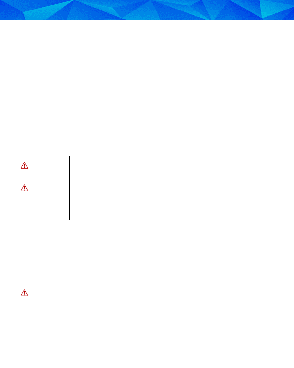
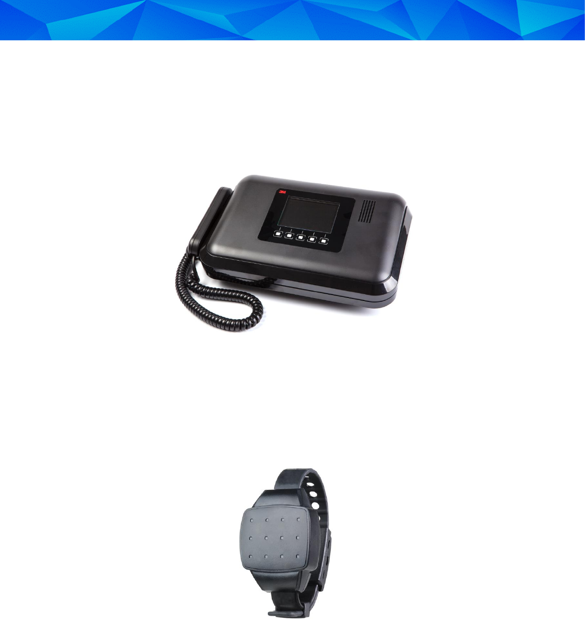
Figure 1: Dual Comms Monitoring Receiver
The unit comprises an RF transceiver, 3G cellular modem, PSTN modem, telephone handset,
rechargeable lithium-ion backup battery and a menu-driven LCD interface.
Communication with the transmitter worn by the offender and the data transfer to the monitoring station
are fully encrypted as a means of ensuring data confidentiality and authentication.
The Dual Comms receiver supports up to 15 offenders at a single curfew location.
Figure 2: RF Transmitter
Each monitored offender is assigned an RF transmitter which is physically attached to their body. The RF
transmitter sends periodic signals that are utilized by the Dual Comms receiver to determine the presence
of the monitored offender. The Dual Comms receiver generates events that are communicated to the
monitoring center in order to report if the offender is adhering to the conditions of their curfew program.
The Dual Comms receiver includes a number of tamper detection mechanisms including tilt, power, and
telephone line detection. Attempts to disconnect or move the unit are immediately reported. The unit also
includes an internal rechargeable battery that provides back-up power in the event of an extended power
outage.

Installation Guide: 3M™ Dual Comms RF Monitoring System and RF Transmitter
10
2 Installing the Dual Comms Receiver
Installing the Dual Comms receiver involves:
Assembling the appropriate equipment
Verifying that the offender is registered in the 3M™ Web Offender Management Software
Locating the optimal position for the unit in the offender’s curfew site
Setting up the unit
2.1 Before Installation
Before leaving the monitoring center, check that you have the correct installation kit and the appropriate
installation tools. In addition, verify that the offender is correctly registered in the 3M™ Web Offender
Management Software application.
2.1.1 Installation Equipment
The kit of installation equipment should include the following items:
Dual Comms receiver
Power adapter
Telephone cables
RF transmitter with strap holder
Locking clips
2.1.2 Installation Tools
You will also need the following installation tools:
Manual Reset Device (MRD) – for activating the RF Transmitter
Strap locking tool – for locking the RF Transmitter
0.2” (5mm) flat head screwdriver – for opening the locking clip
Snake eye screwdriver – for changing the straps on the RF transmitter
2.1.3 Verifying Offender Information in the Web Offender Management Software
Verify the following Offender details in the 3M™ Web OMS:
Offender’s ID, name and address
Offender’s program type –RF Curfew Dual (E4)
Equipment serial numbers – These must match the serial numbers on the equipment you are
planning to install
Landline number
SIM card details
For more information about working with the 3M™ Web Offender Management Software, refer to the
3M Dual Comms Curfew RF Monitoring System Operational Guide.
3M Electronic Monitoring
11
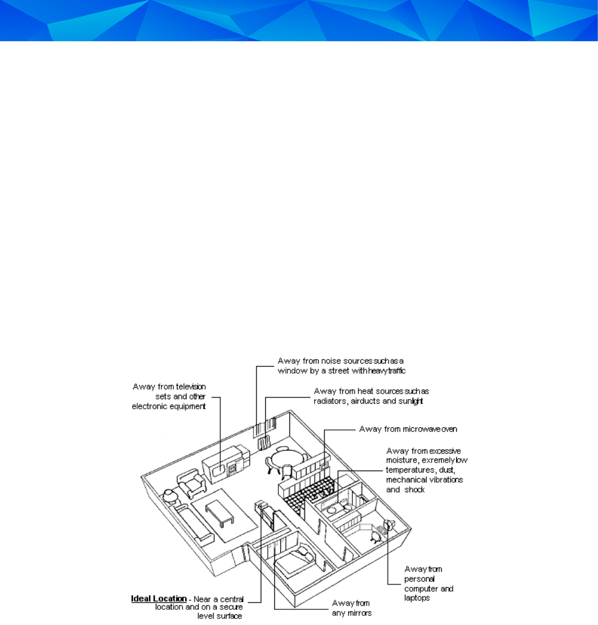
2.2 Placing the Receiver
The ideal location for the Dual Comms receiver is:
In an open area
As close as possible to the center of the curfew site
On a flat and secure surface
1m (3 feet) above the ground and at least 30cm (1 foot) away from the wall
Make sure the RF Dual Comms receiver is located far away from:
Television sets or other electrical appliances
Microwave ovens
Personal computers or laptops
Disruptive noise sources such as heavy traffic or mechanical vibrations
Heat sources such as a radiator, air ducts or direct sunlight
Excessive moisture or extremely low temperatures
Mirrors or reflective materials
Figure 3: Positioning the Curfew Unit
Installation Guide: 3M™ Dual Comms RF Monitoring System and RF Transmitter
12
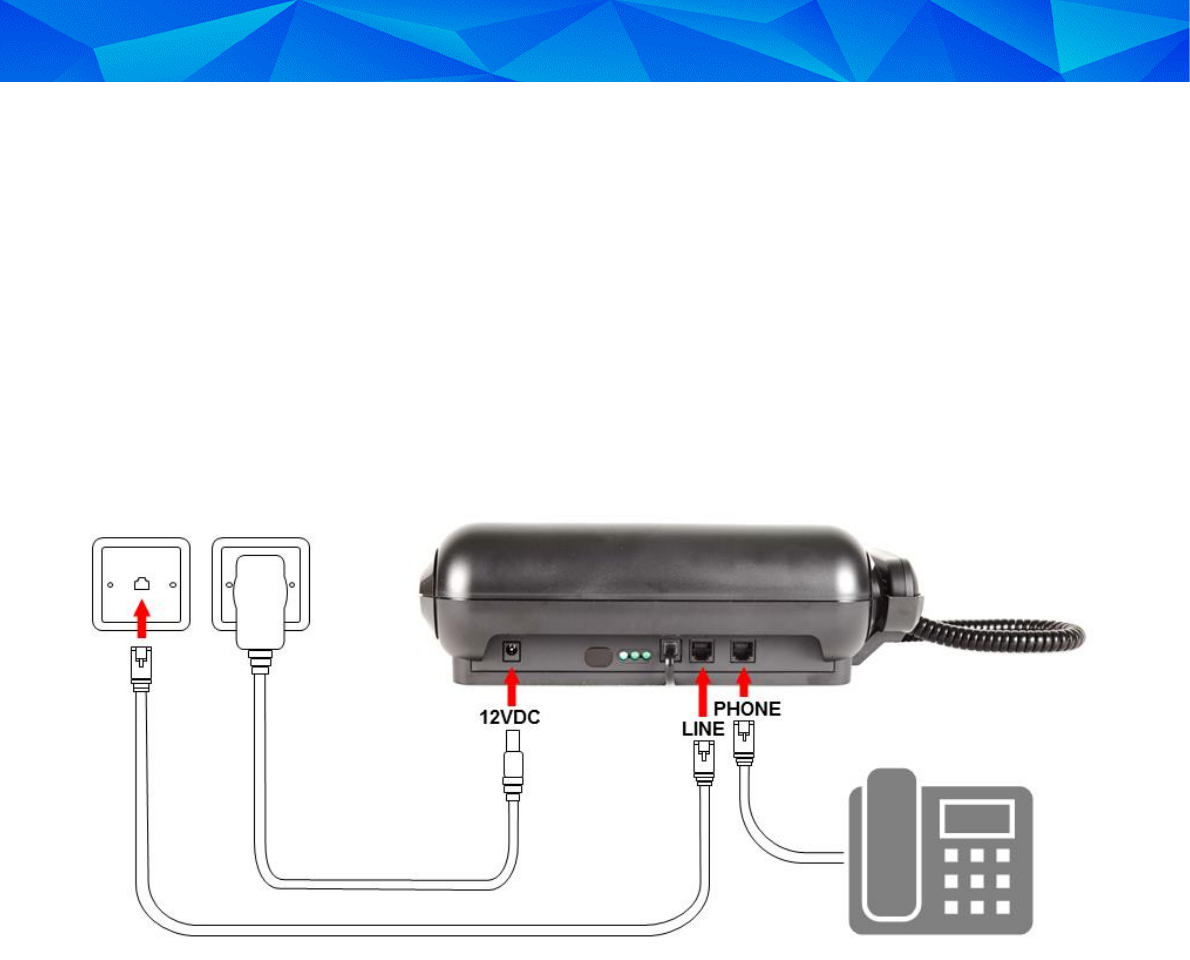
2.3 Installing the Receiver
For the Dual Comms receiver to receive and transmit signals with maximum efficiency, the unit should be
positioned horizontally on a hard, flat surface. The Dual Comms receiver should also be positioned within
easy reach of a power outlet.
To install the Dual Comms receiver:
1. If there is a telephone already connected to the telephone wall socket, disconnect the telephone
cable connect it to the Phone socket located on the back panel of the Dual Comms receiver.
2. Connect one end of the supplied telephone cable into the Line socket located on the back panel
of the Dual Comms receiver and plug the other end into the telephone wall socket.
Figure 4: Dual Comms Receiver Connections
3. Connect the power adapter to the nearest available power outlet.
4. Plug the other end of the supplied power adapter cord into the socket labelled 12VDC on the back
panel of the Dual Comms receiver.
The left and right LEDs, located on the back panel, are turned on. This indicates that the Dual
Comms receiver is functioning correctly.
The LED indicators are:
Left - indicates that external power is connected.
Right - indicates that the unit has at least one working communication channel
The Dual Comms receiver automatically switched to standby mode.
3M Electronic Monitoring
13
3 Installing the RF Transmitter
After the Dual Comms receiver has been connected and is working correctly, you can activate, calibrate
and install the RF transmitter (TX).
Check that you have the following equipment items before you install the RF transmitter:
RF transmitter (TX) and strap holder
Electronic key (MRD)
Locking tool
Locking clips (male and female)
0.2” (5mm) flat head screwdriver – for opening the locking clip
Snake eye screwdriver – for changing the straps of the RF transmitter
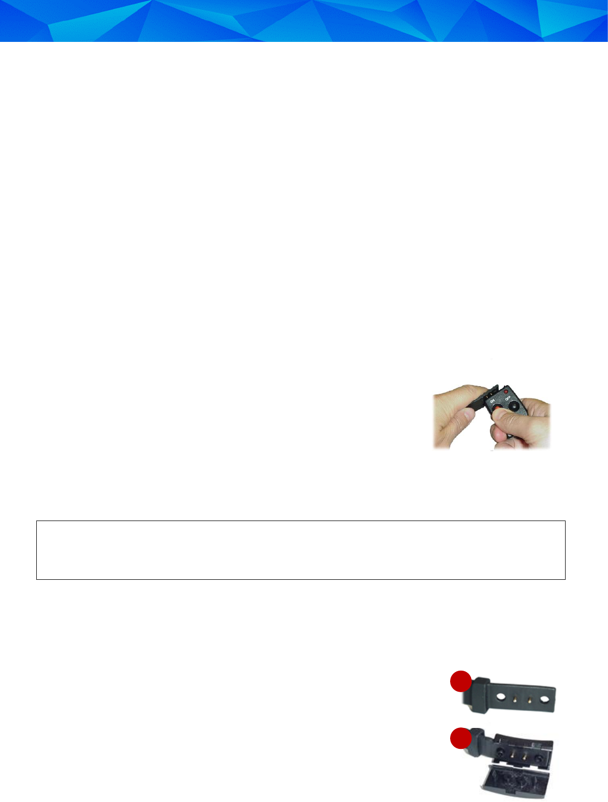
3.1 Activating the RF Transmitter
Before the RF Transmitter can be attached to the offender, you must first activate the RF Transmitter.
To activate the RF transmitter:
1. Hold the free end of the RF transmitter strap in your hand with the
metal pins pointing towards you.
2. Hold the MRD in your other hand, with the two connection points
facing the metal pins.
3. Press the metal pins on the RF transmitter onto the two connection
points on the MRD and hold them in this position.
4. On the MRD, press the ON button.
The red LED on the MRD turns on for 2 seconds and then flashes for another 2 seconds. The
flashing indicates that the RF Transmitter has passed the first phase of its activation.
If the RF Transmitter failed to receive the activation command, the red LED on the MRD turns off
after initially being on for two seconds. If the MRD’s battery is low, the red LED flashes for two
seconds immediately after the ON button is pressed.
5. Place the RF transmitter on its side on a non-metal surface and leave it untouched for 60 seconds
to allow it to calibrate.
The RF Transmitter is now activated.
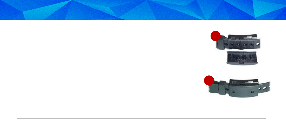
3.2 Attaching the RF Transmitter
To attach the RF transmitter:
1. Place the strap holder over the short strap of the RF transmitter (A).
2. Attach the female part of the clip to the underside of the
short strap ensuring that the closed end of the clip fits snugly
onto the end of the strap (B).
3. Wrap the RF Transmitter around the wrist or ankle at its
narrowest point.
A
B
Installation Guide: 3M™ Dual Comms RF Monitoring System and RF Transmitter
14
4. Lay the long strap over the female part of the clip ensuring that the
strap pins and the clip studs are protruding through the holes in the
long strap (C).
5. Slide the strap holder over the end of the long strap in order to hold
the strap in place.
6. Move the RF Transmitter around the wrist or ankle to ensure that it
fits comfortably.
7. Place the male part of the clip over the female part, ensuring that
the grooves on each side of the clips match (D).
8. Place one side of the locking tool underneath the clip and close the two parts together. You
should hear a clicking sound indicating that the clip is properly locked.
Be sure to collect all of the installation equipment at the offender’s curfew site. This includes any
locking clips that may have broken during the installation.
C
D
3M Electronic Monitoring
15
4 Activating the Offender’s Monitoring Program
After installing the monitoring equipment, you can download the offender’s program configuration and
perform a range test.
4.1 Performing Registration
To perform registration:
Connect the Dual Comms receiver to power.
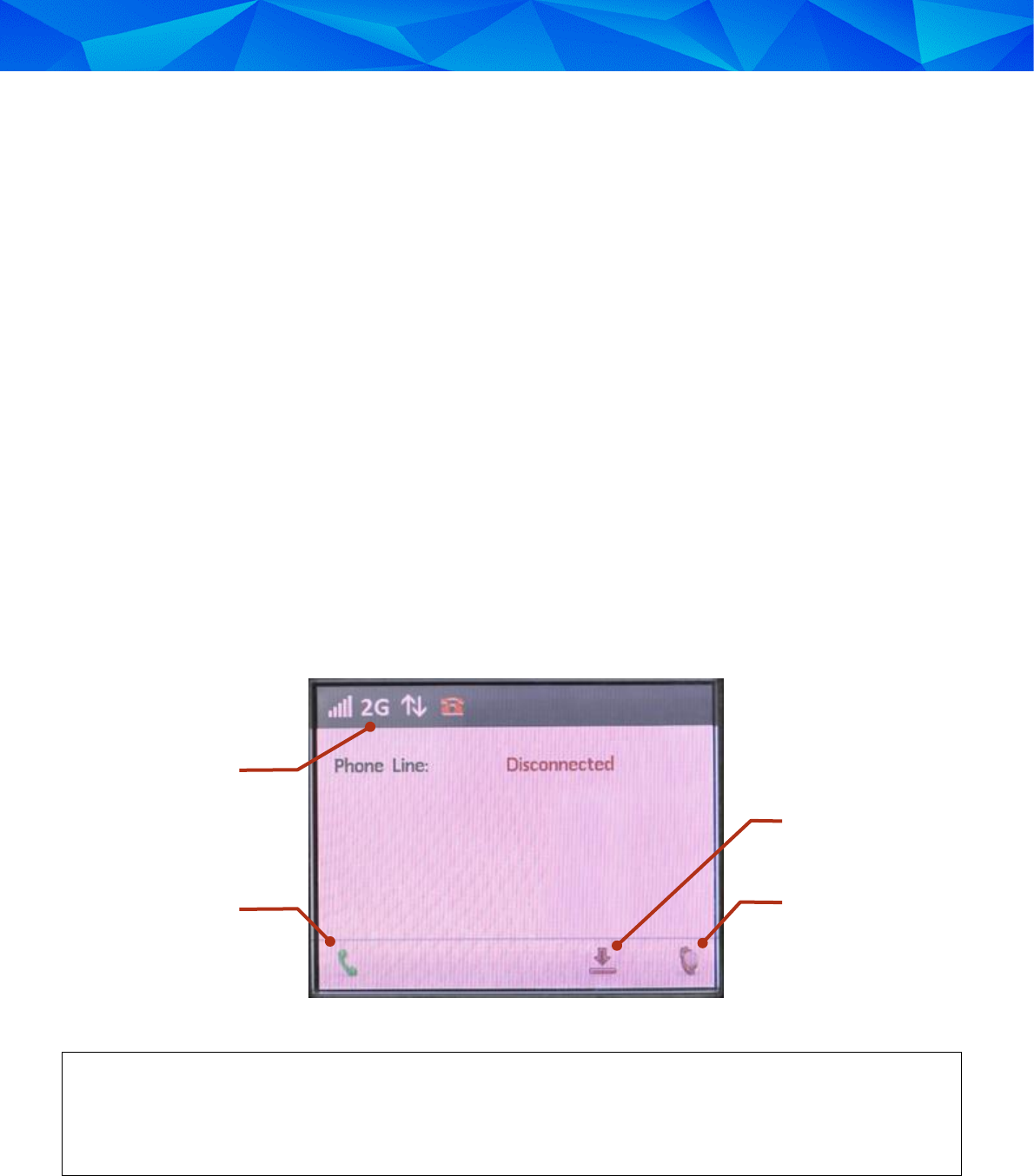
The registration screen is displayed. The initial registration of the voice, data and phone line
communication is automatically performed.
After registration, the following communication status icons are displayed on the Dual Comms receiver’s
main screen:
Cellular reception
Cellular network (2G or 3G)
Data communication
Phone Line
Figure 5: Post-Registration Status Icons on Initial Screen
White communication status icons indicate that the status is OK. Red icons indicate that the
status is not OK. If a problem is detected with the communication status, the details will be
displayed on the screen. In the above example, the phone line is disconnected so the phone line
icon is red and the cause of the problem is displayed on the LCD.
Add or Replace
Transmitter
Activate
Call
Communication
Status Icons
Installation Guide: 3M™ Dual Comms RF Monitoring System and RF Transmitter
16
4.2 Assigning the Transmitter
When activating the Dual Comms receiver, the receiver must be paired with a correctly installed
transmitter – see chapter 3: Installing the RF Transmitter.
To assign a Transmitter to a Dual Comms receiver:
1. From the initial screen (see Figure 5), press the Transmitter button for about 10 seconds until a list
of transmitter serial numbers is displayed.
2. Press the up and down buttons to navigate to the transmitter you installed.
Figure 6: Selecting a Transmitter
3. Press .
The transmitter is paired to the receiver.
4.3 Performing Activation
Dual Comms receiver activation can be performed using one of three methods:
Basic activation
Fast activation
Advanced activation
4.3.1 Basic Activation
Basic activation requires downloading the curfew schedule and general operational parameters by
monitoring center.
To perform Basic activation:
1. Call the monitoring center and ask the monitoring personnel to perform a manual download.
2. At the end of a successful download make sure the unit emits the following series of sounds:
Long Beep, Short Beep, Long Beep, Short Beep.
This sequence of sounds indicates that the download was successful.
3. After the “Download Successful” sound, make sure the unit emits the following sounds:
Long Beep, Short Beep.
3M Electronic Monitoring
17
This sound indicates that the transmitter is OK (the strap is closed, the body is detected and the
battery is OK).
In cases where the unit is monitoring multiple transmitters, the “Transmitter OK” sound is
triggered only for the first transmitter which fulfils the specified conditions.
After the download process has been confirmed as successful, the Receiver Unit will automatically
switch to monitoring mode.
4.3.2 Fast Activation
Fast activation activates the program without modifying the configuration settings.
In order to perform a Fast activation, the monitoring center needs to request a “Download on Next Call”
prior to the activation.
To perform Fast activation:
1. Make sure that a Download Next Call request is waiting in the queue.
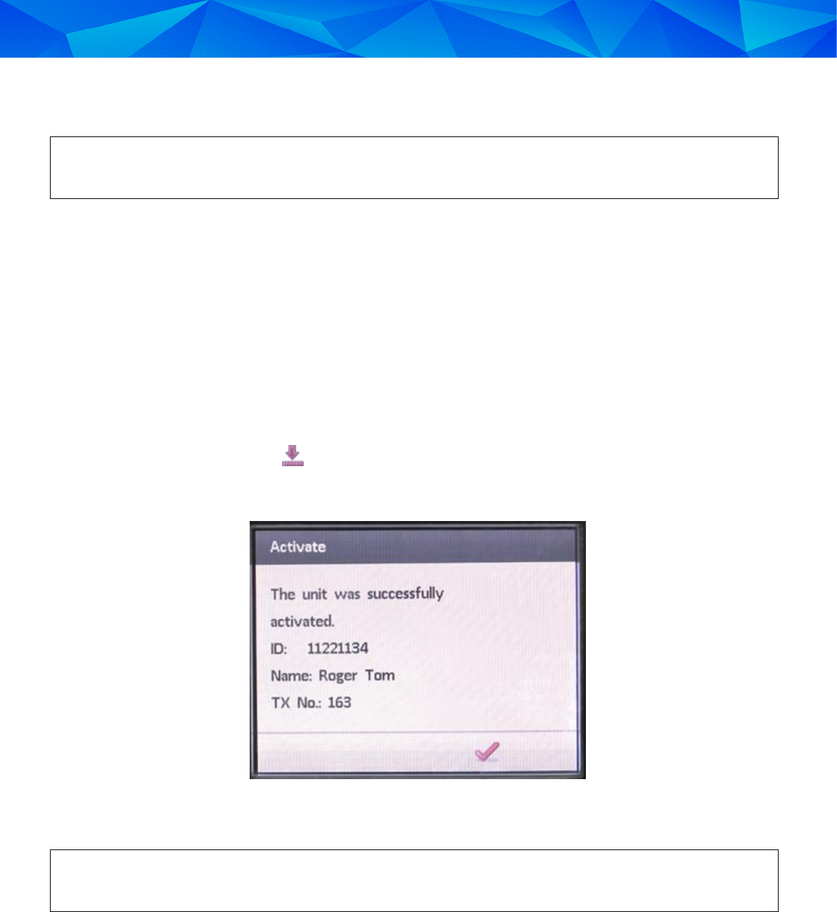
2. Press the Activation icon ( ).
The activation process is performed. After the activation is successfully completed, a success
message is displayed on the screen.
Figure 7: Success Message Example
The Dual Comms receiver and the offender program are now active and in Monitoring mode.
If there is no Download Next Call request in the queue, the Fast activation will fail and the
following message will appear: "Activation Failed - No pending request".
Installation Guide: 3M™ Dual Comms RF Monitoring System and RF Transmitter
18
4.3.3 Advanced Activation
Advanced activation involves modifying the Dual Comms Receiver’s configuration before activating the
unit. To activate the Dual Comms Receiver, you need to make sure that the transmitter is calibrated and
assigned, and that there are communication details defined.
To perform advanced activation:
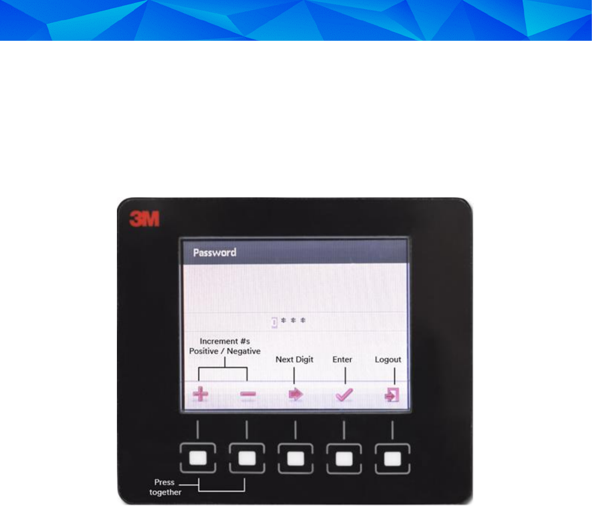
1. Press the second and third buttons (from left to right) together until the Password screen is
displayed.
Figure 8: Password Screen
2. Enter the password that was provided to you by your system administrator.
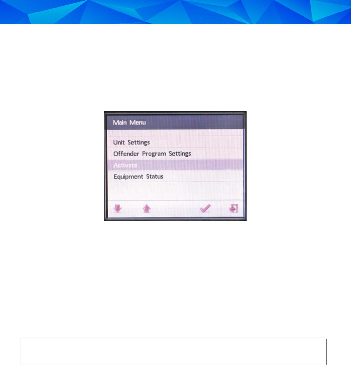
3. The Main Menu screen appears – see Figure 9.
4. Modify the configuration settings as required – see 5 Performing Advanced Configuration.
5. Verify that a Download request is waiting in the queue.
6. From the Main Menu, select Activate.
The activation process is performed during which the Dual Comms receiver communicates with
the Offender Management System and the offender’s program configuration is downloaded.
After activation is successfully completed, a success message is displayed on the Dual Comms
receiver’s LCD screen – see Figure 7.
7. Both the Receiver unit and Offender Program are now active and in Monitoring mode.
3M Electronic Monitoring
19
5 Performing Advanced Configuration
This chapter explains how you can modify the Dual Comms receiver’s configuration settings before
completing the Advanced activation process – see 4.3.3 Advanced Activation.
Configuration can also be performed after the unit is activated.
5.1 Main Configuration Functions
Figure 9: Main Menu
The Dual Comms receiver’s Main Menu includes the following options:
Unit Settings – enables setting the language, date and time, siren volume, and communication
details.
Offender Program Settings – enables setting the following:
o Adding or replacing a transmitter
o Performing a range test and automatically (or manually) setting the receiver’s range
o Setting a temporary schedule
Activate – Initiates the activation process
Equipment Status – Enables you to view the transmitter and receiver status
After the activation is successfully completed, it is recommended to disable the Main Menu
from the application in the monitoring center.
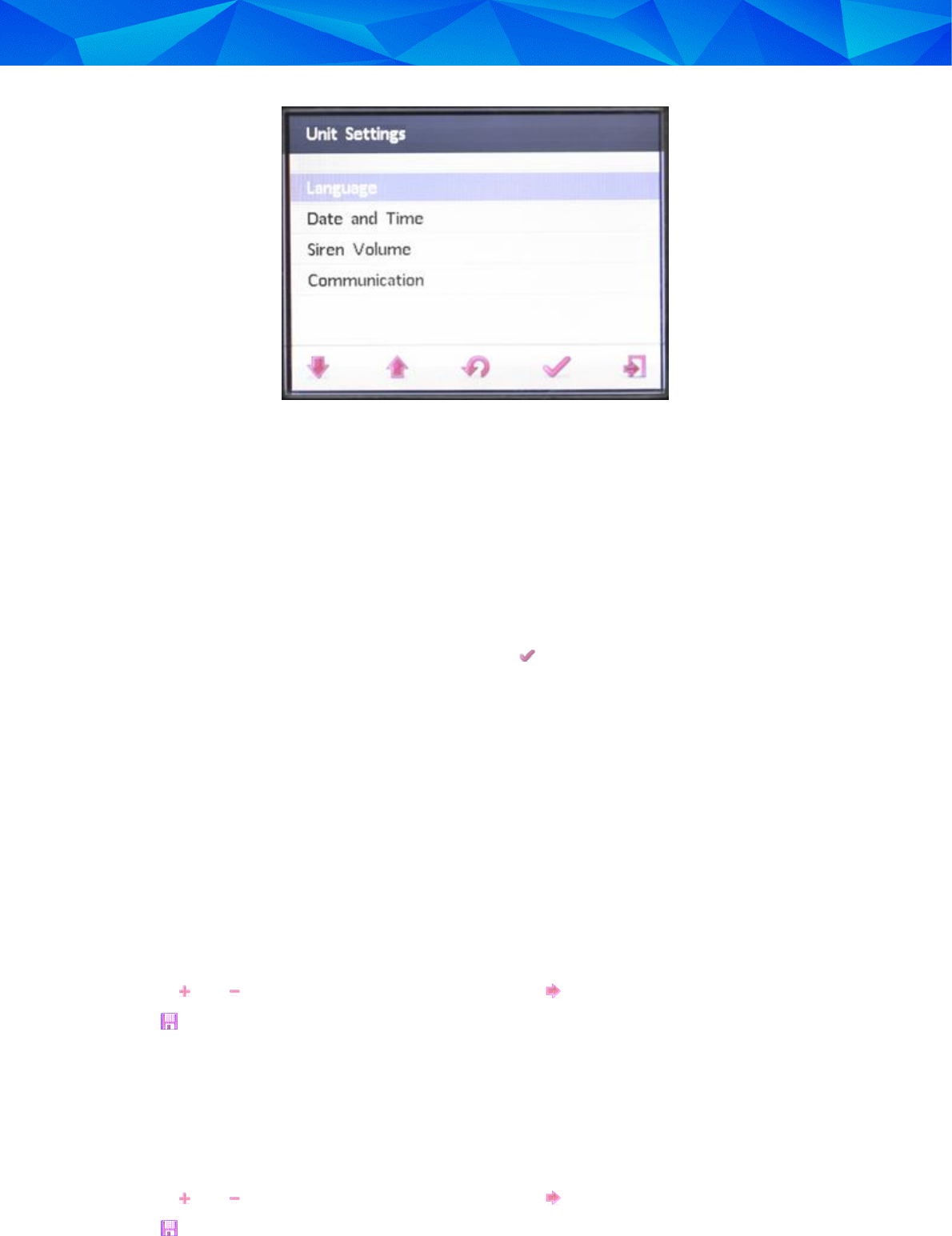
5.2 Configuring Unit Settings
The Unit Settings screen enables you to set the language, date and time, siren volume and
communication details.
Installation Guide: 3M™ Dual Comms RF Monitoring System and RF Transmitter
20
Figure 10: Unit Settings Menu
5.2.1 Setting the Language
The Language setting enables you to change the language displayed on the LCD interface.
To set the language:
1. From the Main Menu, select Unit Settings.
2. Select Language.
3. Select a language from the list displayed and press .
5.2.2 Setting the Date and Time Configuration
Setting the date and time is an optional feature that is relevant only before the unit is activated. Following
activation, the date and time are synchronized with Offender Management System.
In addition to setting the date and time, various options are available that allow you to configure how the
date and time will be displayed
To set the date:
1. From the Main Menu, select Unit Settings.
2. Select Date and Time.
3. Select Date.
4. Use the and buttons to configure the date and the button to move right.
5. Press to save.
To set the time:
1. From the Main Menu, select Unit Settings.
2. Select Date and Time.
3. Select Time.
4. Use the and buttons to configure the time and the button to move right.
5. Press to save.

3M Electronic Monitoring
21
To configure the date and time display:
1. From the Main Menu, select Unit Settings.
2. Select Date and Time.
3. Select Date and Time Display.
4. Choose one of the following options:
Hide Date and Time
Show Date and Time
5. Press to save.
To set the date format:
1. From the Main Menu, select Unit Settings.
2. Select Date and Time.
3. Select Date Format.
4. Choose one of the following date formats:
DD/MM/YYYY
MM/DD/YYYY
YYYY/MM/DD
5. Press to save.
To set the time format:
1. From the Main Menu, select Unit Settings.
2. Select Date and Time.
3. Select Time Format.
4. Choose one of the following time formats:
24 Hours
12 Hours
5. Press to save.
5.2.3 Setting the Siren Volume
To set the time format:
1. From the Main Menu, select Unit Settings.
2. Select Siren Volume.
3. Choose one of the following siren volume options:
Low
Medium (default)
High
4. Press to save.
Installation Guide: 3M™ Dual Comms RF Monitoring System and RF Transmitter
22
5.3 Defining the Communication Details
The Communication Details are the telephone numbers, IP and port of the Offender Management
System’s communication gateway.
To set the communication details:
1. From the Main Menu, select Unit Settings.
2. Select Communication.
3. Enter the following parameters:
Landline Number
Cellular Number
IP Address
Port Number
4. Press to save.
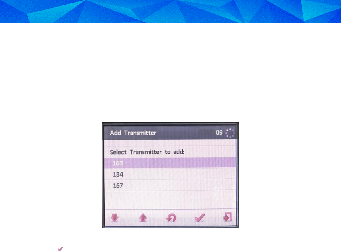
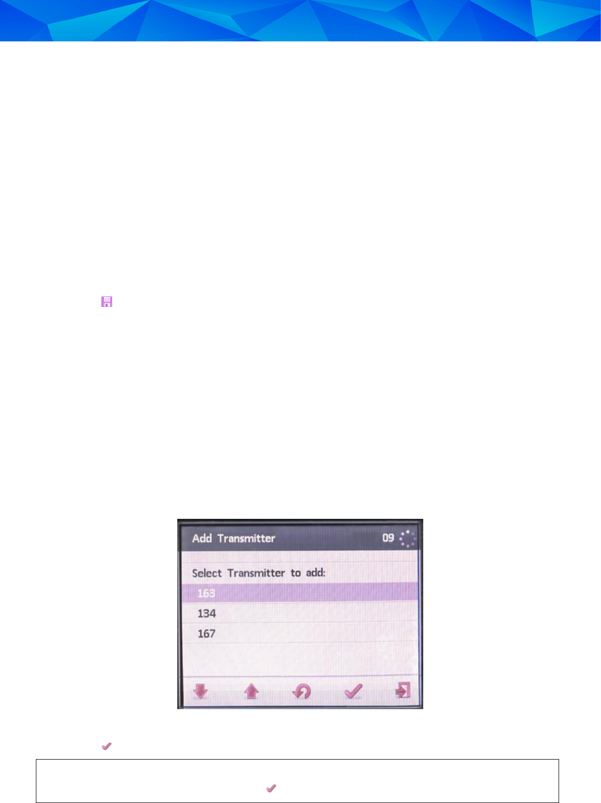
5.4 Adding or Replacing a Transmitter
After the Dual Comms receiver is activated, it is possible to add or replace transmitters.
To add a new transmitter or replace the existing transmitter:
1. From the Main Menu, select Offender Program Settings.
2. Select Transmitter.
3. Select Add Transmitter to add a new transmitter or Replace Transmitter to replace an existing
one.
A list of serial numbers of transmitters in range of the Dual Comms receiver is displayed.
4. Press the up and down buttons to navigate to the transmitter you want to add.
Figure 11: Selecting a Transmitter
5. Press .
If you chose to replace a transmitter, the message “The unit is monitoring transmitter number [XXX]. Do
you want to replace it?” is displayed. Press to confirm transmitter replacement.

3M Electronic Monitoring
23
5.5 Setting the Temporary Curfew Schedule
Setting a temporary curfew schedule is an optional feature that is relevant to units that cannot be
activated in the Offender Management System at the time of installation. For example, the Dual Comms
receiver is installed in a location with no cellular coverage and a telephone line is due to be installed at a
later date.
It is important to note the following:
You can only set a temporary curfew schedule after manually setting the date and time
– see 5.2.2: Setting the Date and Time Configuration.
The temporary curfew schedule is effective from the same date that it was set.
The Dual Comms is capable of monitoring using a temporary curfew schedule but the events
generated will be reported to the Offender Management System only once the Dual Comms
receiver has been successfully activated.
If you do not set a temporary curfew schedule, the offender must stay within range of the Dual Comms
receiver at all times. Leaving the curfew area will generate a violation event.
The temporary curfew schedule allows you to configure one time frame during which the offender can
leave the curfew area. Alternatively, you can configure a time frame during which the offender must
leave the curfew area and failure to do so will generate a violation event.
To set the temporary curfew schedule:
1. From the Main Menu, select Offender Program Settings.
2. Select Temporary Curfew Schedule.
3. Enter the Start Time of the time frame.
4. Enter the End Time of the time frame.
5. Choose the Type of time frame:
Out – the offender can leave the curfew area during the time frame.
Must Be Out – the offender must leave the curfew area during the time frame.
6. Press to save.
Installation Guide: 3M™ Dual Comms RF Monitoring System and RF Transmitter
24
6 Setting the RF Range
The Dual Comms receiver supports five RF range settings. The RF range can either be set automatically
using the Range Test feature or you can choose the range manually.
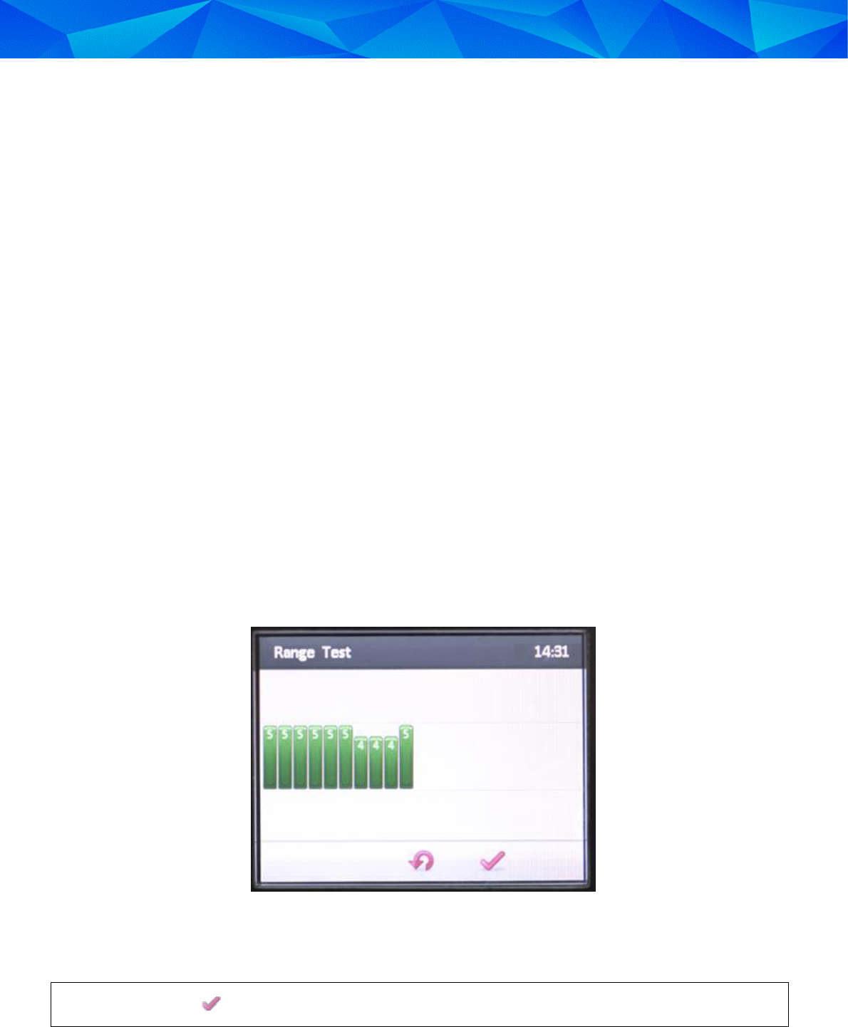
6.1 Performing a Range Test
A range test helps you to determine that the Dual Comms receiver is positioned in the optimum location
to receive signals from the RF transmitter from all positions within the offender’s curfew site. It also helps
you to set a suitable RF range for the receiver.
While performing a range test you should escort the offender to the following types of locations:
Places where the offender may be located for long periods of time, such as the living room,
bedroom or bathroom
Remote locations where the offender is permitted, such as the garage, cellar or backyard.
Locations within the curfew site that are furthest from the receiver.
Behind large metal objects.
To perform a range test:
1. From the Main Menu, select Offender Program Settings.
2. Select Range.
3. Select Range Test.
The Dual Comms receiver starts the range test.
Figure 12: Range Test Example
4. Escort the Offender around the curfew site. Wait to hear at least four beeps in each test location
to verify that the RF Transmitter’s signals are successfully reaching the Receiver.
You can press to terminate the range test at any time.
After the test is completed, the Dual Comms receiver automatically sets the best range for the
transmitter according to the test results.

3M Electronic Monitoring
25
6.2 Manually Setting the RF Range
To manually set the RF range:
1. From the Main Menu, select Offender Program Settings.
2. Select Range.
3. Select Manual Selection.
4. Choose one of the following options:
Very short
Short
Medium
Long
Maximum
5. Press to save.

Installation Guide: 3M™ Dual Comms RF Monitoring System and RF Transmitter
26
7 Daily Operating Instructions
The Dual Comms receiver is capable of receiving incoming calls from the monitoring center and enables
the offender to perform outgoing calls to the monitoring center or to emergency services.
7.1 Incoming Voice Calls
The Dual Comms receiver can receive incoming calls to its cellular modem. On receiving an incoming
call, the Dual Comms receiver sounds a ring tone.
Incoming calls include:
Calls from the monitoring center or officers.
Voice Verification Test calls (if the offender’s program includes voice verification).
If the Dual Comms receiver is connected to the offender’s landline, the line may be shared with a regular
telephone on which the offender receives regular calls from friends or family. Incoming landline calls do
not cause the Dual Comms receiver to ring.
Upon answering a call to their landline telephone, the offender may hear a slight noise on the
line during the first few seconds of the conversation. The offender should not be alarmed. The
Dual Comms receiver automatically interacts with each incoming call for the first few seconds.
If, during a conversation on the landline telephone, the Dual Comms receiver emits a short tone
on the line, it means that the Dual Comms receiver unit needs to communicate with the Offender
Management System. The offender should complete their current conversation as soon as
possible to enable the Dual Comms receiver to make its call. Failure to free the line could
register as a violation.
To answer an incoming call to the Dual Comms receiver’s cellular modem:
When the Dual Comms receiver sounds a ring tone, lift up the handset and press .
To hang up an incoming call to the Dual Comms receiver’s cellular modem:
Press and place the handset in its cradle.
7.2 Incoming Data Calls
Incoming data calls can be defined as a communication session between the Dual Comms receiver and
the Offender Management System’s communication gateway.
When the Offender Management System communicates with the Dual Comms receiver via the cellular
network, the receiver does not ring and the offender will be unaware of the communication session in
progress.
However, if the Offender Management System communicates with Dual Comms receiver via landline, the
offender’s telephone will ring and the Dual Comms receiver answers the call following a pre-defined
number of rings.
When monitoring center staff perform a download via landline, the offender should be
instructed beforehand not to pick up the phone when it rings.
The offender should be instructed that if they pick up their telephone and hear modem sounds,
they must hang up the phone immediately and not attempt to use the phone for 10 minutes.
3M Electronic Monitoring
27
7.3 Outgoing Calls from the Dual Comms Receiver
The Dual Comms receiver has the capability to make the following types of outgoing calls via its cellular
modem:
Emergency calls to the monitoring center or emergency services. The phone numbers for these
contacts are stored in the Dual Comms receiver’s memory.
Voice Verification test request calls.
7.3.1 Performing an Outgoing Call
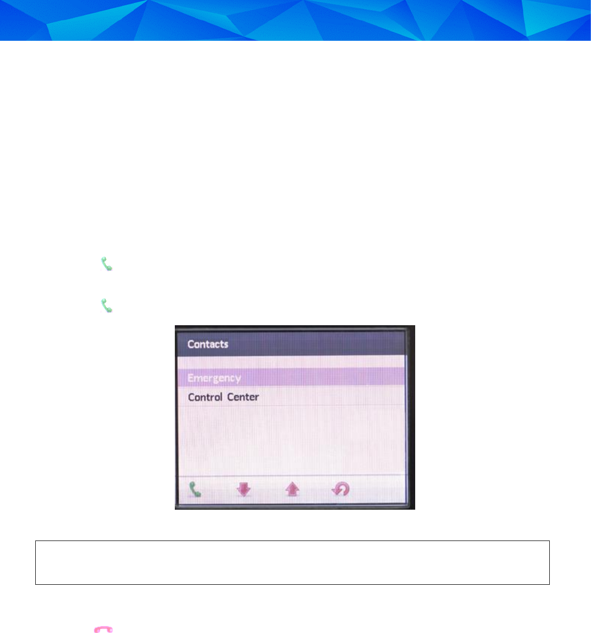
To make an outgoing call from the Dual Comms receiver:
1. Lift the Dual Comms receiver’s handset.
2. Press .
3. Choose a contact (Emergency or Control Center).
4. Press .
Figure 13: Emergency and Control Center Calling Options
If you hear a low beeping sound while attempting to make an outgoing call via the Dual Comms
receiver, the outgoing call attempt has failed.
To hang up the call:
Press and place the handset in its cradle.

Installation Guide: 3M™ Dual Comms RF Monitoring System and RF Transmitter
28
7.4 General Rules for the Offender
The following are general rules for the Offender regarding their monitoring program:
Never…
Move the Dual Comms receiver after it has been installed
Place any objects on top of the Dual Comms receiver
Disconnect the Dual Comms receiver’s power cord
Attempt to open the Dual Comms receiver
Leave the designated curfew area during the defined curfew time frame
Attempt to open the RF transmitter’s strap
Cut the RF transmitter’s strap or break the clips