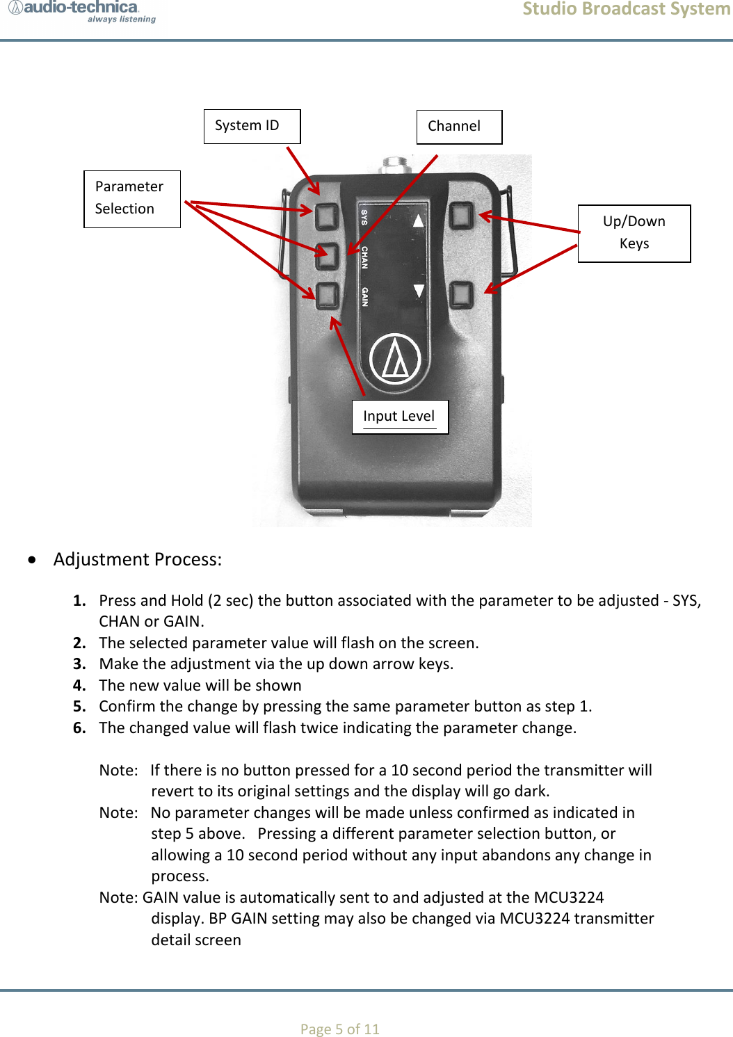
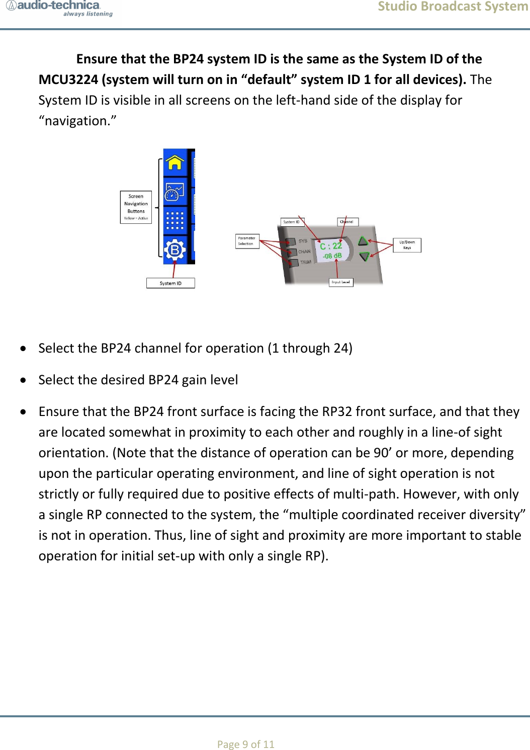
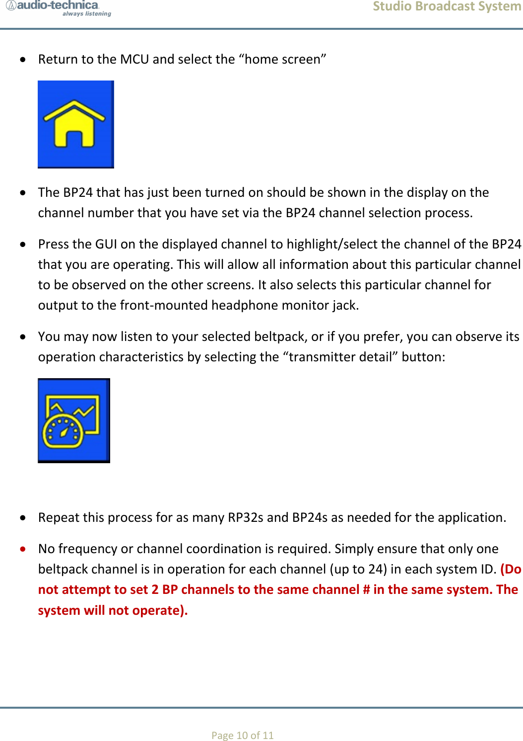
Audio Technica BP24 Studio Broadcast UWB Wireless Microphone System User Manual Studio Broadcast System

Audio-Technica Corporation Studio Broadcast UWB Wireless Microphone System Studio Broadcast System

Contents

User Manual

       Studio Broadcast System SET UP and USE  BP24 Bodypack Transmitter
Studio Broadcast System    Page 2 of 11 1. REGULATORY AND COMPLIANCE STATEMENTS ............................................................................................................ 3  2.  BP24 BODYPACK TRANSMITTER .....................................................................................................................................   3.    POSITIONING AND SET UP…………………………………………………………………………………………………………………………………………..  4.  SYSTEM QUICK START  ................................................................................................................................................
Studio Broadcast System    Page 3 of 11   1. REGULATORY AND COMPLIANCE
Studio Broadcast System    Page 4 of 11   2   BP24 UWB Body Pack Transmitter 2.1 Transmitter Controls  An On/Off power switch is located in the battery compartment.      The adjustable transmitter parameters are: 1. System ID (SYS) – Each transmitter must be assigned a system ID (1-9) that must match the system ID set on the MCU3224   The transmitter will only transmit when it receives a sync pulse and matching system ID from an active system.   This will prevent users with transmitters assigned the same channel slot on a different system from interfering if they enter the coverage area.    Note:  RP timing signals from separate systems must be RF isolated from one another to prevent system timing contention in transmitters.  2. Channel Number (CHAN) – The channel slot assigned to the transmitter (01-24.)  Each transmitter in the system is assigned a unique channel number.    3. Input level (GAIN) – Adjustment of the audio input level (0 dB to 20dB in 2dB Steps).    The adjustable transmitter parameters are shown on a display located on the face of the transmitter.     The display will only be illuminated when the user is adjusting the transmitter.   Pressing any button will activate the display for 10 seconds.  After 10 seconds, display functions will no longer be illuminated although the BP is functioning. Pressing any button will light the display in order to check for power or operating condition.
Studio Broadcast System    Page 5 of 11      Adjustment Process: 1. Press and Hold (2 sec) the button associated with the parameter to be adjusted - SYS, CHAN or GAIN. 2. The selected parameter value will flash on the screen. 3. Make the adjustment via the up down arrow keys.  4. The new value will be shown  5. Confirm the change by pressing the same parameter button as step 1. 6. The changed value will flash twice indicating the parameter change.   Note:   If there is no button pressed for a 10 second period the transmitter will revert to its original settings and the display will go dark.  Note:   No parameter changes will be made unless confirmed as indicated in step 5 above.   Pressing a different parameter selection button, or allowing a 10 second period without any input abandons any change in process.  Note: GAIN value is automatically sent to and adjusted at the MCU3224 display. BP GAIN setting may also be changed via MCU3224 transmitter detail screen System ID Channel  SYSTEM ID Input Level  SYSTEM ID Parameter Selection Up/Down Keys
Studio Broadcast System    Page 6 of 11 2.2 Batteries The BP24 operates via 2 x AA size batteries.    When inserting the batteries into the BP24, observe correct polarity as marked.  Do not peel off or damage the outer tube of the battery. Do not use a leaking battery. If battery leakage occurs, avoid contact with skin. If contact occurs, immediately was thoroughly with soap and water. If battery leakage comes into contact with your eyes, immediately flush with water and seek medical attention. Do not expose batteries to fire. Do not heat, deform, solder, disassemble or modify batteries.   For best operation, do not use batteries of different types together, old or new batteries together, or batteries with different charge levels.  2.3 Transmitter Audio Output Routing    The system includes a talkback function utilizing 48 output channels in either the MADI stream or DANTE/AVB network output. In normal operation, audio will be routed to the audio channel that matches the channel slot number assigned (Audio Channel = CHAN = 1 - 24).  The talkback function is activated by connecting the appropriate transmitter connector contact (TBD) to ground when the in-line talkback switch is depressed. The talkback function is a press and hold operation. While the talkback button is depressed, the audio output will be routed to a channel in the range of 25 to 48 - equal to the channel slot number + 24 (Audio Channel = CHAN +24). Upon button release, the audio channel returns to the normal operation on the assigned channel 1-24.
Studio Broadcast System    Page 7 of 11                                                        3. Positioning  When wearing the bodypack transmitter, is it important to remember that the front of the unit (the portion on which the display and controls are located) contains the unit’s antenna. This antenna requires a clear path to and from the rp32 receiver in order for the unit to operate properly.  Place the display side (front side) of this bodypack transmitter facing out, and not directly against or towards a body or other solid object.  Specifically, the antenna is located directly under the Audio-Technica logo on the front of this unit. Holding or continuously touching the logo directly over the antenna may de-tune the unit and negatively affect performance.       4. System QUICK START  Using a shielded CAT 5 cable (may be used with up to 1,000 feet of cable per channel) terminated with a standard RJ45 connector, plug the cable into the RJ45 input jack on the rear of at least RP32 receiver. Connect the other end of the CAT 5 cable to the RJ45 input jack on the rear of the MCU3224 main control unit. You may connect up to 32 RP32 receivers by connecting them into the corresponding channel output (1-32) found on the rear of the MCU.  You do not need to turn the RP on. It receives power via the CAT 5 cable from the MCU 3224. The RP display should immediately light and display the channel output number to which it has been connected on the MCU.
Studio Broadcast System    Page 8 of 11  Apply power to the MCU3224 by connecting at least one IEC cable to AC wall supply.   Press the front panel “power” button. The power light(s) corresponding to the IEC cable input will be visible on the front panel (one red and one blue), and the GUI screen will illuminate and enter a “set-up” mode while the system is normalizing and preparing for operation. Once the system is available for operation, the GUI screen will display a “HOME SCREEN.”    On the left-hand side of the screen, select the “Matrix” button:   This will allow the user to view and confirm that the desired number of RPs are connected to the system with the desired channel # assignments.   Place 2 x AA batteries into a BP24 beltpack transmitter and slide the internal power switch into the on position.
Studio Broadcast System    Page 9 of 11 Ensure that the BP24 system ID is the same as the System ID of the MCU3224 (system will turn on in “default” system ID 1 for all devices). The System ID is visible in all screens on the left-hand side of the display for “navigation.”        Select the BP24 channel for operation (1 through 24)  Select the desired BP24 gain level    Ensure that the BP24 front surface is facing the RP32 front surface, and that they are located somewhat in proximity to each other and roughly in a line-of sight orientation. (Note that the distance of operation can be 90’ or more, depending upon the particular operating environment, and line of sight operation is not strictly or fully required due to positive effects of multi-path. However, with only a single RP connected to the system, the “multiple coordinated receiver diversity” is not in operation. Thus, line of sight and proximity are more important to stable operation for initial set-up with only a single RP).
Studio Broadcast System    Page 10 of 11  Return to the MCU and select the “home screen”   The BP24 that has just been turned on should be shown in the display on the channel number that you have set via the BP24 channel selection process.   Press the GUI on the displayed channel to highlight/select the channel of the BP24 that you are operating. This will allow all information about this particular channel to be observed on the other screens. It also selects this particular channel for output to the front-mounted headphone monitor jack.  You may now listen to your selected beltpack, or if you prefer, you can observe its operation characteristics by selecting the “transmitter detail” button:    Repeat this process for as many RP32s and BP24s as needed for the application.   No frequency or channel coordination is required. Simply ensure that only one beltpack channel is in operation for each channel (up to 24) in each system ID. (Do not attempt to set 2 BP channels to the same channel # in the same system. The system will not operate).
Studio Broadcast System    Page 11 of 11

Navigation menu