Audio Technica M2TL In Ear Monitor System User Manual P52001 M2 System OM
Audio-Technica Corporation In Ear Monitor System P52001 M2 System OM
UserManual.wiki
>
Audio Technica
>
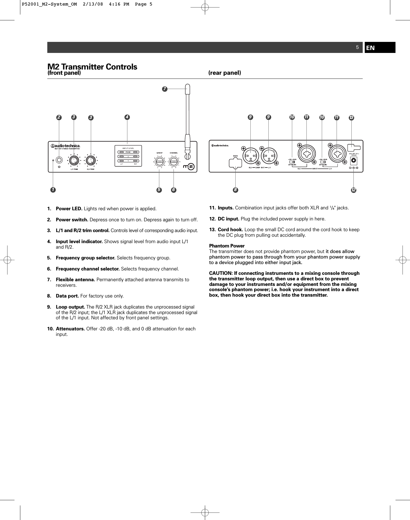
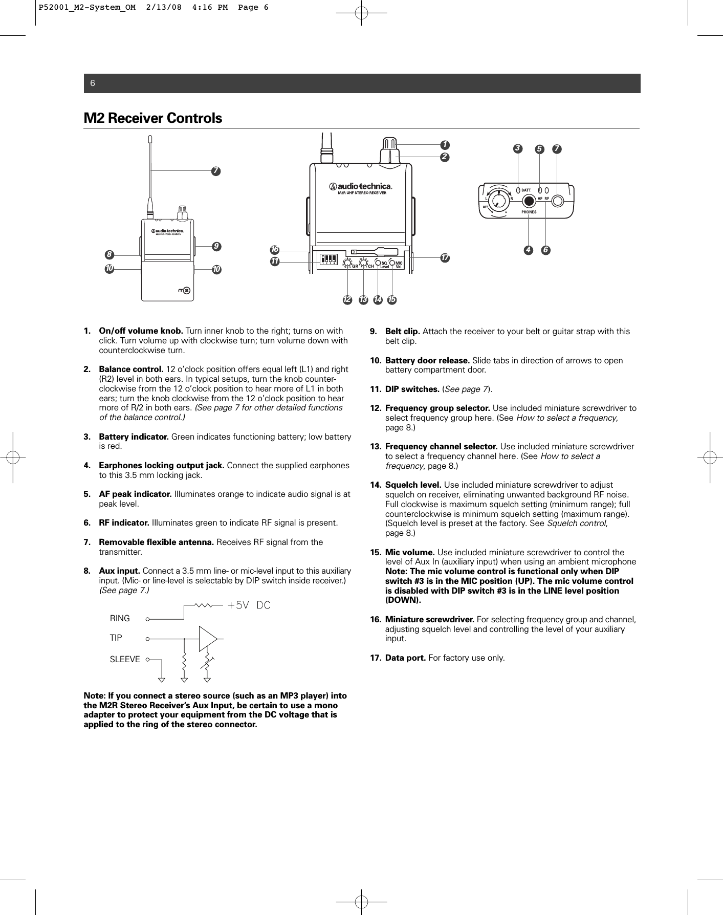
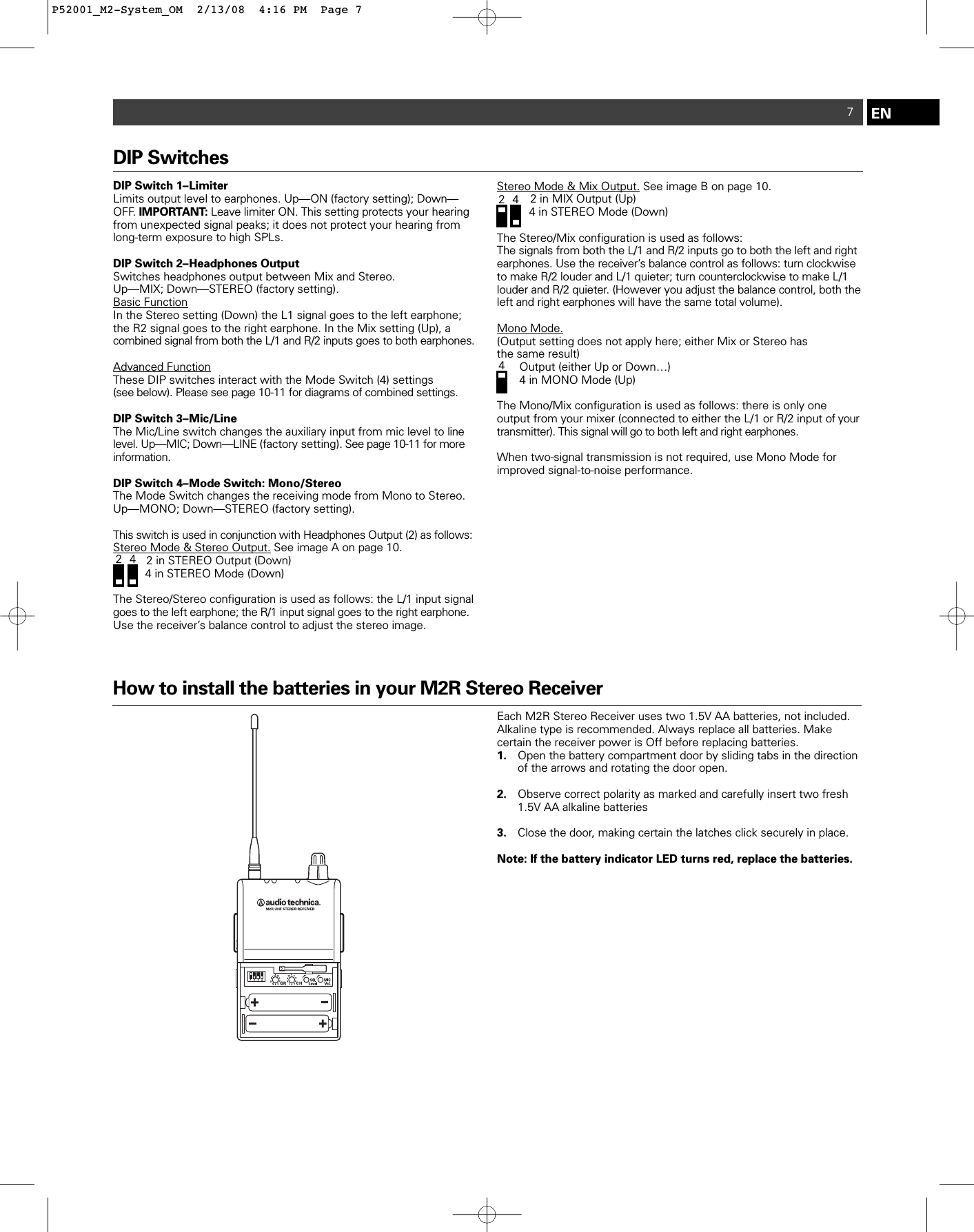
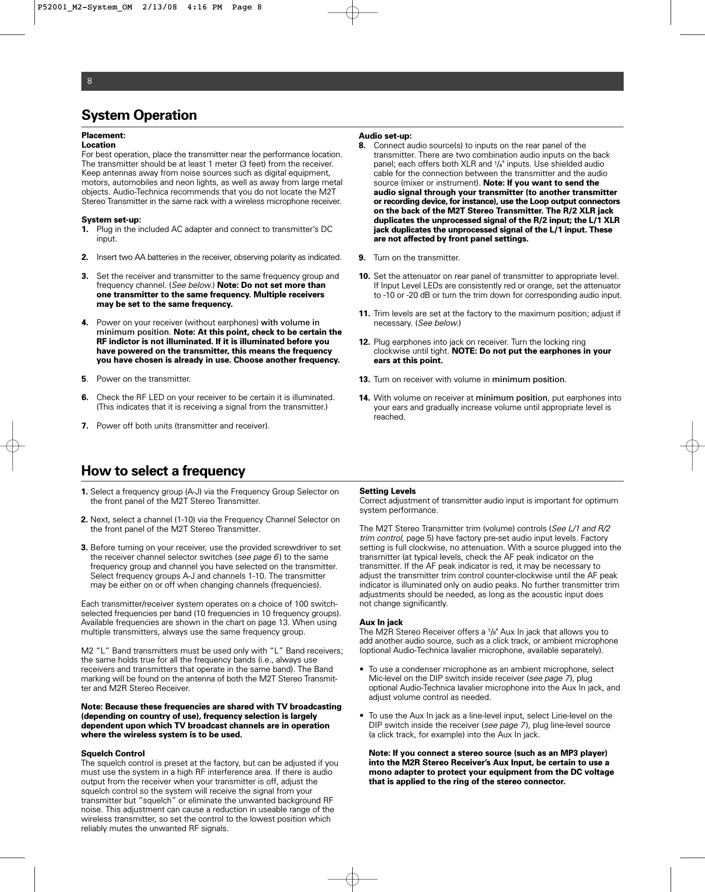
M2TL User Manual
Users Manual
Navigation menu
Upload a User Manual
Namespaces
Wiki Guide
HTML
PDF
Info
Views
User Manual
Discussion / Help
Navigation