Audio Technica M2TL In Ear Monitor System User Manual P52001 M2 System OM
Audio-Technica Corporation In Ear Monitor System P52001 M2 System OM
Users Manual
wireless
wireless
wireless
wireless
wireless
M2
Wireless In-Ear Monitor System
Set-up and Operation Pages 2-13
Installation et utilisation Pages 14-25
Configuración y funcionamiento Páginas 26-37
Configuração e operação Páginas 38-49
Impostazioni e Utilizzo Pagine 50-61
Einrichtung und Betrieb Seiten 62-73
Opstelling en gebruik Pagina 74-85
!
0168
P52001_M2-System_OM 2/13/08 4:16 PM Page 1

WARNING!
USE AS LOW A VOLUME AS POSSIBLE. PERMANENT HEARING DAMAGE
CAN RESULT FROM USING THIS SYSTEM AT EXCESSIVE VOLUMES.
For safe operation of this in-ear monitor system, do not listen at excessive
sound pressure levels.
Most national safety and health administrations have established guidelines
for maximum time being exposed to sound pressure levels before hearing
damage occurs.
85 dB(A) SPL at 8 hours
88 dB(A) SPL at 4 hours
91 dB(A) SPL at 2 hours
94 dB(A) SPL at 1 hour
97 dB(A) SPL at 30 minutes
100 dB(A) SPL at 15 minutes
120 dB(A) SPL — avoid or hearing damage may occur
In live settings it is difficult to make exact measurements of Sound
Pressure Levels (SPL) present at the eardrum, which is affected not only
by the In-Ear Monitor volume, but by ambient sound on the stage and
other factors.
To protect your ears from hearing damage:
• Use the in-ear monitor system at the lowest volume possible; turn up
the volume only enough to hear
• Be aware that ringing in your ears may indicate that the volume is set
too high.
• Have your ears examined regularly by an audiologist.
• If wax builds up in your ears, stop using the in-ear monitor system
until you have seen an audiologist.
• To avoid infections, use an antiseptic to wipe the earphones before
and after using the system.
• Stop using the earphones if you experience ear discomfort or infection.
This device complies with the European R&TTE directive 1999/05/EC.
Operation is subject to the condition that this device does not cause
harmful interference. For Licensing information, please contact your local
dealer or radio authority.
This device complies with part 15 of the FCC Rules. Operation is subject to
the condition that this device does not cause harmful interference.
This device complies with INDUSTRY CANADA R.S.S. 210, en conformité
avec IC: RSS-210/CNR210.
Operation is subject to the following conditions: 1) This device may not cause
harmful interference and 2) this device must accept any interference received,
including interference which may cause undesired operation. Changes or
modifications not expressly approved by Audio-Technica could void your
authority to operate this equipment.
2
Notice to individuals with implanted cardiac pacemakers or AICD
devices: Any source of RF (radio frequency) energy may interfere with
normal functioning of the implanted device. All wireless microphones have
low-power transmitters (less than 0.05 watts output) which are unlikely to
cause difficulty, especially if they are at least a few inches away. However,
since a “body-pack” mic transmitter typically is placed against the body, we
suggest attaching it at the belt, rather than in a shirt pocket where it may
be immediately adjacent to the medical device. Note also that any medical-
device disruption will cease when the RF transmitting source is turned off.
Please contact your physician or medical-device provider if you have any
questions, or experience any problems with the use of this or any other RF
equipment.
CAUTION! The circuits inside the receiver and transmitter have been precisely
adjusted for optimum performance and compliance with federal regulations.
Do not attempt to open the receiver or transmitter. To do so will void the
warranty, and may cause improper operation.
Warning: To prevent fire or shock hazard, do not expose this appliance to
rain or moisture.
• To avoid electrical shock, do not open the cabinet. Refer servicing to
qualified personnel only.
• Do not expose this apparatus to drips and splashes.
• Do not place any objects filled with liquids such as vases on the apparatus.
• Do not install this apparatus in a confined space such as a bookcase or
similar unit.
• The apparatus should be located close enough to the AC outlet so that you
can easily grasp the AC adapter at anytime.
Dispose of batteries in an environmentally responsible manner according
to the local laws and regulations of your region. Some batteries may be
recycled, and may be accepted for disposal at your local recycling center. If
you are not able to identify the applicable rules in your area, please check
the instructions of the battery manufacturer.
Do not dispose of batteries in a fire or trash incinerator, or leave batteries
in hot places such as an automobile under direct sunlight. Do not store
batteries near an oven, stove, or other heat source.
About RF Interference
Please note that wireless frequencies are shared with other radio services.
According to Federal Communications Commission regulations,
“Wireless microphone operations are unprotected from interference from
other licensed operations in the band. If any interference is received by
any Government or non-Government operation, the wireless microphone
must cease operation...” If you need help with operation or frequency
selection, please contact your local dealer or Audio-Technica. Extensive
wireless information also is available at www.audio-technica.com.
Warning—Use as low volume levels as possible.
To prevent damage to your eardrums, never use this system at excessive
volume levels. Listening to loud sounds for an extended period may
cause temporary or permanent hearing damage.
P52001_M2-System_OM 2/13/08 4:16 PM Page 2
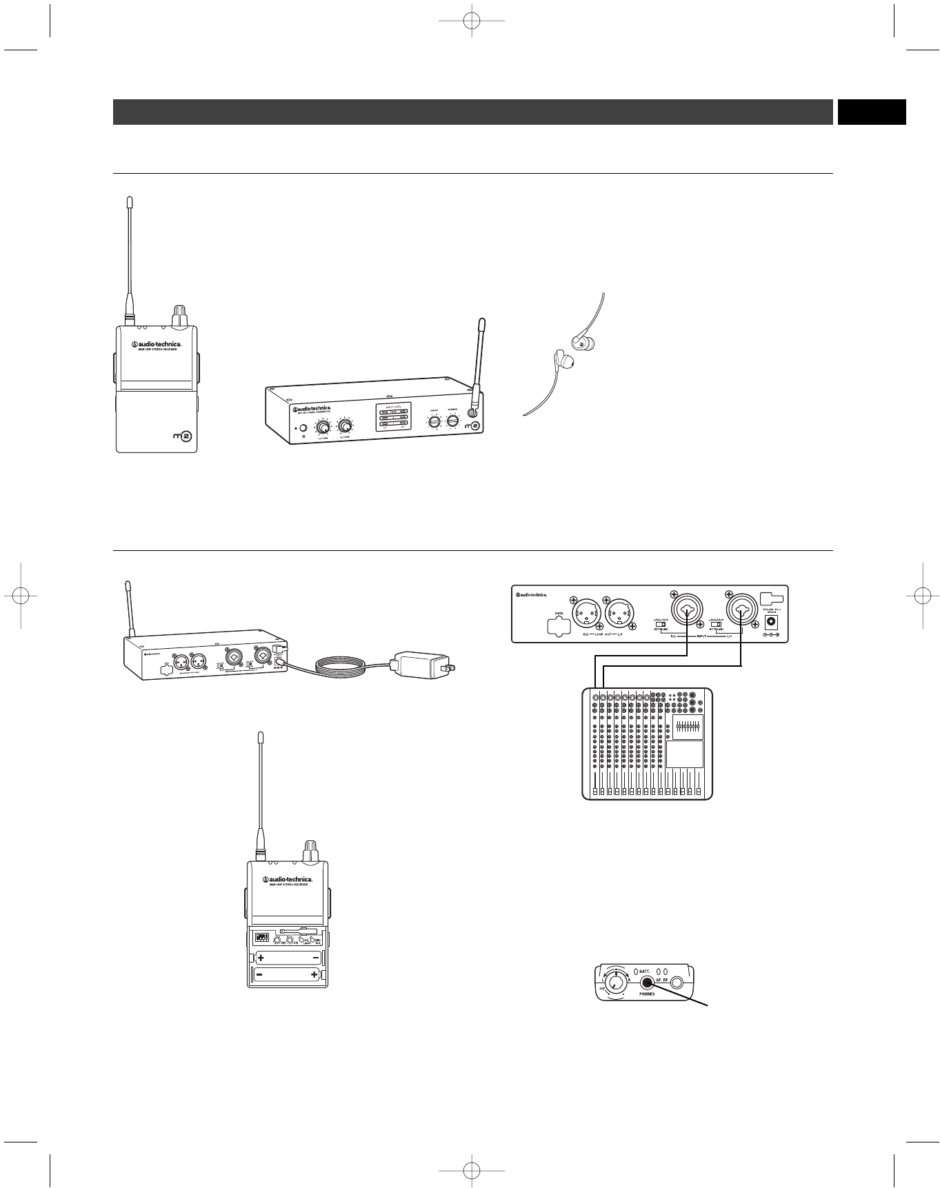
M2 System Components
M2R
UHF Stereo Receiver M2T
UHF Stereo Transmitter with
AC adapter
EP3
Dynamic Earphones
3
Quick-start guide
1. Plug in the included AC adapter and connect to transmitter’s DC input.
2. Insert 2 AA batteries in the M2R Stereo Receiver following polarity
as indicated.
3. Set M2R Stereo Receiver and M2T Stereo Transmitter to the same
frequency. (
See page 8.
)
4. Power on M2R Stereo Receiver with volume in minimum position;
power on M2T Stereo Transmitter. Check to see that RF LED on
M2R Stereo Receiver is illuminated.
5. Power off receiver and transmitter.
6. Connect audio source(s) to inputs on the rear panel of the transmitter.
7. Power on M2T Stereo Transmitter.
8. Adjust attenuator on rear panel of M2T Stereo Transmitter to
appropriate level. (
See page 5.
)
9. Adjust trim level on front panel of M2T Stereo Transmitter, if needed.
(
See page 8.
)
10. Plug supplied Dynamic Earphones into earphones locking output
jack on M2R Stereo Receiver. NOTE: Do not put the earphones
in your ears at this point.
11. Turn on receiver with volume in minimum position.
12. With volume on receiver at minimum position, put earphones into
your ears and gradually increase volume until appropriate level is
reached.
EN
P52001_M2-System_OM 2/13/08 4:16 PM Page 3

4
Thank you for buying the Audio-Technica M2 Wireless In-Ear Monitor
System. This feature-rich in-ear monitor system is designed to provide
you with comfortable high-fidelity sound on stage.
The M2 is a frequency-agile in-ear monitor system designed to make
stage monitoring more effective, comfortable, portable, and intelligible.
The M2R Stereo Receiver allows the user to create and control his/her
own mix on stage with Personal Mix Control that offers independent
control of volume and mix at the receiver. The M2T Stereo Transmitter
offers two 1/4"/XLR combo input connectors into which users can connect
line-level inputs (from a mixing console, for example). The supplied
earphones are equipped with a proprietary Audio-Technica dynamic
driver offering a full frequency response and richly detailed high-fidelity
sound. The clean, articulate mix allows performers to hear themselves at
comfortable SPLs. The earphones come with three sizes of rubber flexible
eartips and a universal-fit foam tip for a custom fit, increased isolation and
long-wearing listening comfort.
Note: M2 “L” Band receivers must be used only with “L” Band
transmitters; the same holds true for M2 “M,” “E,” and “F” Band
receivers and transmitters. For multiple-channel applications, as
many as ten systems may be used together per frequency band.
M2 Wireless In-Ear Monitor System – Introduction
System Features
• High-fidelity sound with clean, articulate mix allows you to
hear yourself better at lower volumes
• 100 selectable UHF channels
• Up to 10 simultaneous systems per frequency band
• Three receiver modes: Personal Mix, stereo, and mono
• Personal Mix Control allows you to adjust your own mix on stage
• 3.5 mm line-in jack connects to ambient microphone, click
track & more
• LED indicators provide easy-to-read level monitoring
• XLR loop output (true pass-through) connects signal to mixing
console, additional IEM system or recording device with no
signal degradation
• Adjustable squelch eliminates annoying static
• Pilot tone protects against RF interference when the transmitter
is turned off
• Limiter (defeatable) helps protect your hearing from sudden
peaks
• Portable system is quick to load and set up
• Reduces on-stage audio clutter for better overall mix & less
feedback
• Use any number of M2R Stereo Receivers on the same frequency
• Audio-Technica earphones with proprietary dynamic driver
offer full frequency response and outstanding isolation
• Earphones feature personal fit with 3 sizes of rubber eartips plus
an ear-conforming foam tip
P52001_M2-System_OM 2/13/08 4:16 PM Page 4
5
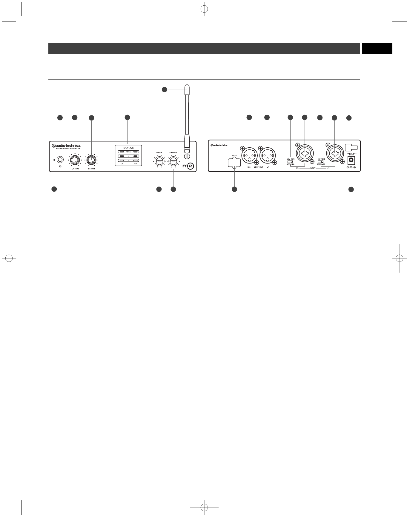
M2 Transmitter Controls
(front panel) (rear panel)
1. Power LED. Lights red when power is applied.
2. Power switch. Depress once to turn on. Depress again to turn off.
3. L/1 and R/2 trim control. Controls level of corresponding audio input.
4. Input level indicator. Shows signal level from audio input L/1
and R/2.
5. Frequency group selector. Selects frequency group.
6. Frequency channel selector. Selects frequency channel.
7. Flexible antenna. Permanently attached antenna transmits to
receivers.
8. Data port. For factory use only.
9. Loop output. The R/2 XLR jack duplicates the unprocessed signal
of the R/2 input; the L/1 XLR jack duplicates the unprocessed signal
of the L/1 input. Not affected by front panel settings.
10. Attenuators. Offer -20 dB, -10 dB, and 0 dB attenuation for each
input.
11. Inputs. Combination input jacks offer both XLR and 1/4" jacks.
12. DC input. Plug the included power supply in here.
13. Cord hook. Loop the small DC cord around the cord hook to keep
the DC plug from pulling out accidentally.
Phantom Power
The transmitter does not provide phantom power, but it does allow
phantom power to pass through from your phantom power supply
to a device plugged into either input jack.
CAUTION: If connecting instruments to a mixing console through
the transmitter loop output, then use a direct box to prevent
damage to your instruments and/or equipment from the mixing
console’s phantom power; i.e. hook your instrument into a direct
box, then hook your direct box into the transmitter.
EN
23410 11 13
9
7
1812
5 6
3910 11
P52001_M2-System_OM 2/13/08 4:16 PM Page 5
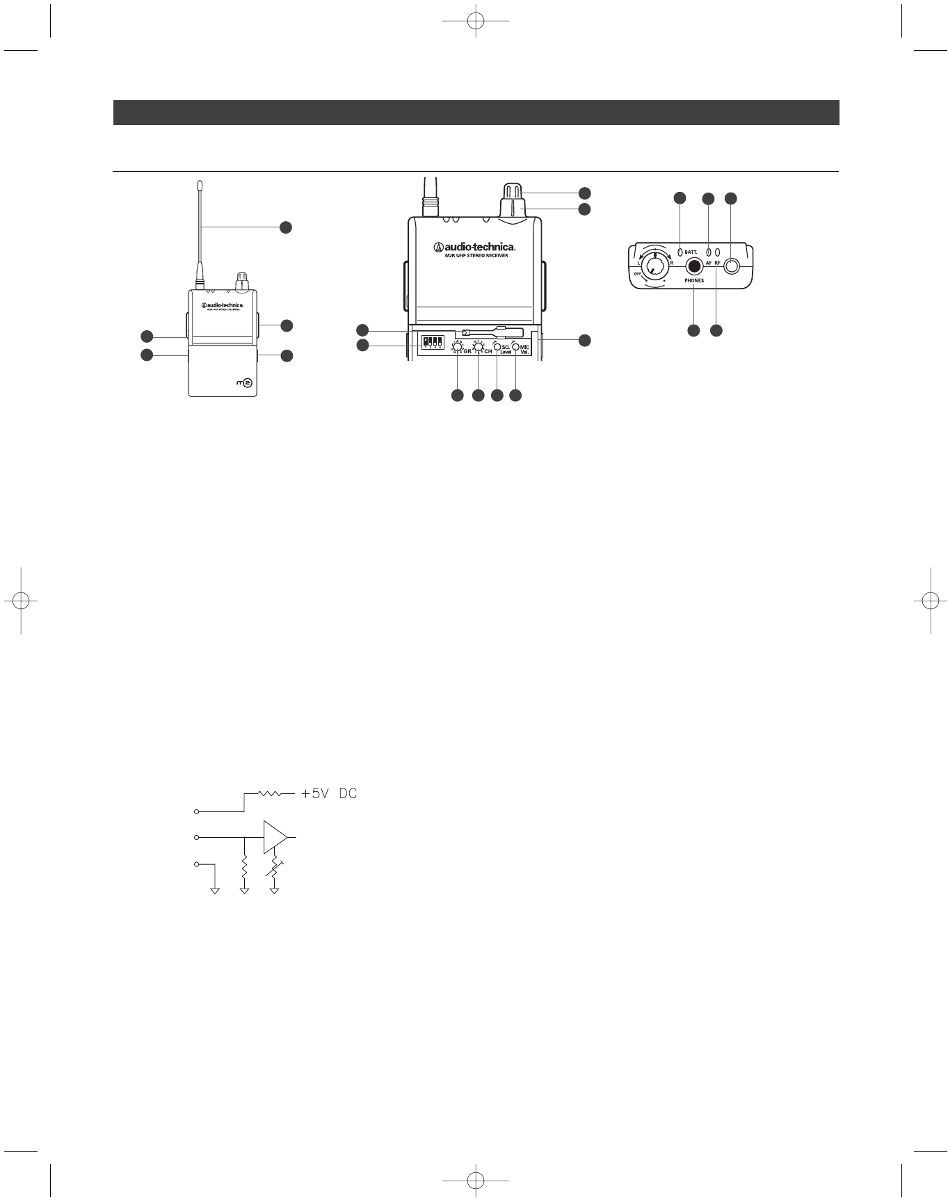
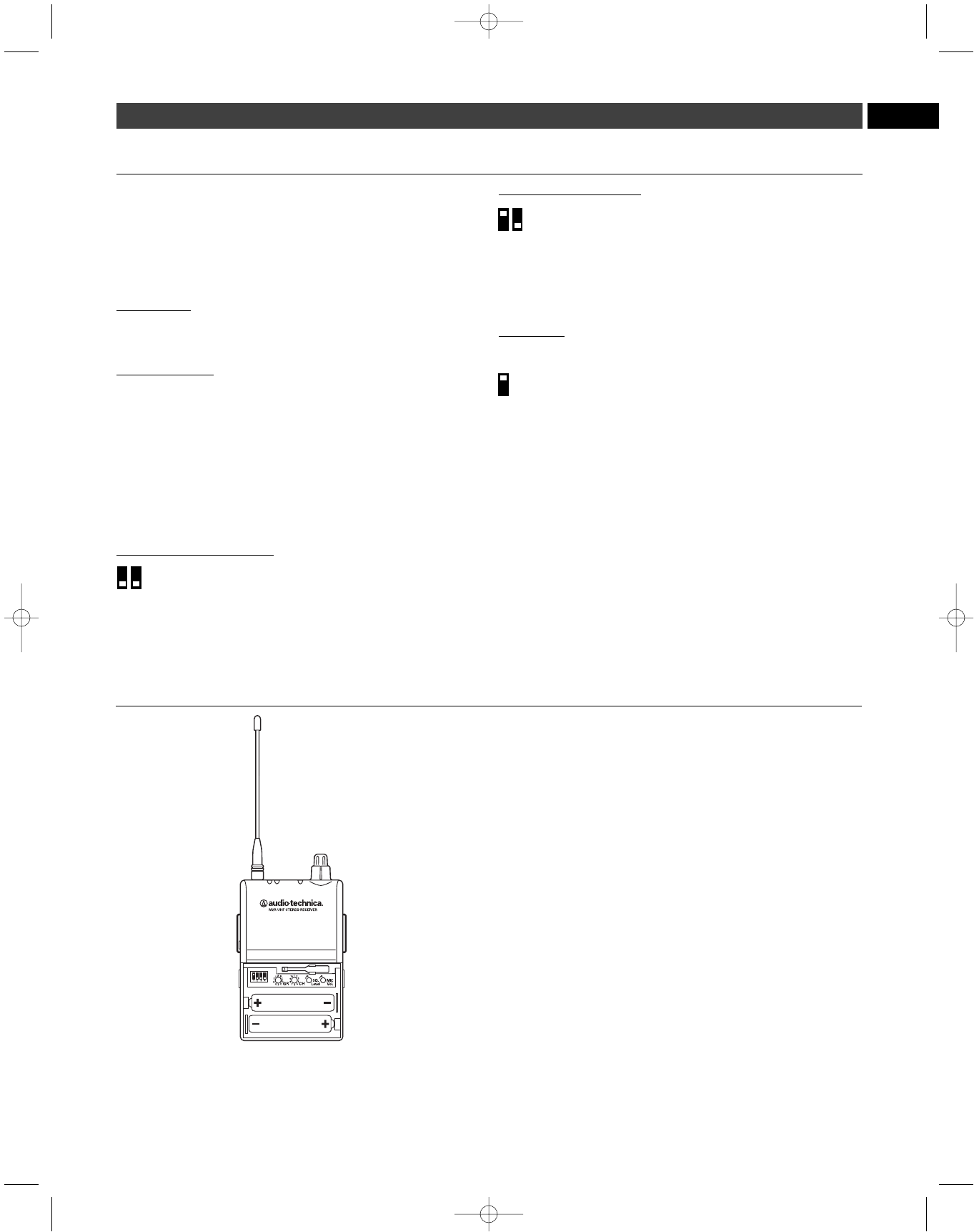
M2 Receiver Controls
1. On/off volume knob. Turn inner knob to the right; turns on with
click. Turn volume up with clockwise turn; turn volume down with
counterclockwise turn.
2. Balance control. 12 o’clock position offers equal left (L1) and right
(R2) level in both ears. In typical setups, turn the knob counter-
clockwise from the 12 o’clock position to hear more of L1 in both
ears; turn the knob clockwise from the 12 o’clock position to hear
more of R/2 in both ears.
(See page 7 for other detailed functions
of the balance control.)
3. Battery indicator. Green indicates functioning battery; low battery
is red.
4. Earphones locking output jack. Connect the supplied earphones
to this 3.5 mm locking jack.
5. AF peak indicator. Illuminates orange to indicate audio signal is at
peak level.
6. RF indicator. Illuminates green to indicate RF signal is present.
7. Removable flexible antenna. Receives RF signal from the
transmitter.
8. Aux input. Connect a 3.5 mm line- or mic-level input to this auxiliary
input. (Mic- or line-level is selectable by DIP switch inside receiver.)
(See page 7.)
Note: If you connect a stereo source (such as an MP3 player) into
the M2R Stereo Receiver’s Aux Input, be certain to use a mono
adapter to protect your equipment from the DC voltage that is
applied to the ring of the stereo connector.
9. Belt clip. Attach the receiver to your belt or guitar strap with this
belt clip.
10. Battery door release. Slide tabs in direction of arrows to open
battery compartment door.
11. DIP switches. (
See page 7
).
12. Frequency group selector. Use included miniature screwdriver to
select frequency group here. (See
How to select a frequency
,
page 8.)
13. Frequency channel selector. Use included miniature screwdriver
to select a frequency channel here. (See
How to select a
frequency
, page 8.)
14. Squelch level. Use included miniature screwdriver to adjust
squelch on receiver, eliminating unwanted background RF noise.
Full clockwise is maximum squelch setting (minimum range); full
counterclockwise is minimum squelch setting (maximum range).
(Squelch level is preset at the factory. See
Squelch control
,
page 8.)
15. Mic volume. Use included miniature screwdriver to control the
level of Aux In (auxiliary input) when using an ambient microphone
Note: The mic volume control is functional only when DIP
switch #3 is in the MIC position (UP). The mic volume control
is disabled with DIP switch #3 is in the LINE level position
(DOWN).
16. Miniature screwdriver. For selecting frequency group and channel,
adjusting squelch level and controlling the level of your auxiliary
input.
17. Data port. For factory use only.
6
2
13
4
57
6
9
10 11
7
12 13 14 15
16 17
8
10
RING
TIP
SLEEVE
P52001_M2-System_OM 2/13/08 4:16 PM Page 6
7
24
DIP Switches
DIP Switch 1–Limiter
Limits output level to earphones. Up—ON (factory setting); Down—
OFF. IMPORTANT: Leave limiter ON. This setting protects your hearing
from unexpected signal peaks; it does not protect your hearing from
long-term exposure to high SPLs.
DIP Switch 2–Headphones Output
Switches headphones output between Mix and Stereo.
Up—MIX; Down—STEREO (factory setting).
Basic Function
In the Stereo setting (Down) the L1 signal goes to the left earphone;
the R2 signal goes to the right earphone. In the Mix setting (Up), a
combined signal from both the L/1 and R/2 inputs goes to both earphones.
Advanced Function
These DIP switches interact with the Mode Switch (4) settings
(see below). Please see page 10-11 for diagrams of combined settings.
DIP Switch 3–Mic/Line
The Mic/Line switch changes the auxiliary input from mic level to line
level. Up—MIC; Down—LINE (factory setting). See page 10-11 for more
information.
DIP Switch 4–Mode Switch: Mono/Stereo
The Mode Switch changes the receiving mode from Mono to Stereo.
Up—MONO; Down—STEREO (factory setting).
This switch is used in conjunction with Headphones Output (2) as follows:
Stereo Mode & Stereo Output. See image A on page 10.
2 in STEREO Output (Down)
4 in STEREO Mode (Down)
The Stereo/Stereo configuration is used as follows: the L/1 input signal
goes to the left earphone; the R/1 input signal goes to the right earphone.
Use the receiver’s balance control to adjust the stereo image.
Stereo Mode & Mix Output. See image B on page 10.
2 in MIX Output (Up)
4 in STEREO Mode (Down)
The Stereo/Mix configuration is used as follows:
The signals from both the L/1 and R/2 inputs go to both the left and right
earphones. Use the receiver’s balance control as follows: turn clockwise
to make R/2 louder and L/1 quieter; turn counterclockwise to make L/1
louder and R/2 quieter. (However you adjust the balance control, both the
left and right earphones will have the same total volume).
Mono Mode.
(Output setting does not apply here; either Mix or Stereo has
the same result)
Output (either Up or Down…)
4 in MONO Mode (Up)
The Mono/Mix configuration is used as follows: there is only one
output from your mixer (connected to either the L/1 or R/2 input of your
transmitter). This signal will go to both left and right earphones.
When two-signal transmission is not required, use Mono Mode for
improved signal-to-noise performance.
4
EN
24
How to install the batteries in your M2R Stereo Receiver
Each M2R Stereo Receiver uses two 1.5V AA batteries, not included.
Alkaline type is recommended. Always replace all batteries. Make
certain the receiver power is Off before replacing batteries.
1. Open the battery compartment door by sliding tabs in the direction
of the arrows and rotating the door open.
2. Observe correct polarity as marked and carefully insert two fresh
1.5V AA alkaline batteries
3. Close the door, making certain the latches click securely in place.
Note: If the battery indicator LED turns red, replace the batteries.
P52001_M2-System_OM 2/13/08 4:16 PM Page 7

8
System Operation
Placement:
Location
For best operation, place the transmitter near the performance location.
The transmitter should be at least 1 meter (3 feet) from the receiver.
Keep antennas away from noise sources such as digital equipment,
motors, automobiles and neon lights, as well as away from large metal
objects. Audio-Technica recommends that you do not locate the M2T
Stereo Transmitter in the same rack with a wireless microphone receiver.
System set-up:
1. Plug in the included AC adapter and connect to transmitter’s DC
input.
2. Insert two AA batteries in the receiver, observing polarity as indicated.
3. Set the receiver and transmitter to the same frequency group and
frequency channel. (
See below.
) Note: Do not set more than
one transmitter to the same frequency. Multiple receivers
may be set to the same frequency.
4. Power on your receiver (without earphones) with volume in
minimum position. Note: At this point, check to be certain the
RF indictor is not illuminated. If it is illuminated before you
have powered on the transmitter, this means the frequency
you have chosen is already in use. Choose another frequency.
5. Power on the transmitter.
6. Check the RF LED on your receiver to be certain it is illuminated.
(This indicates that it is receiving a signal from the transmitter.)
7. Power off both units (transmitter and receiver).
Audio set-up:
8. Connect audio source(s) to inputs on the rear panel of the
transmitter. There are two combination audio inputs on the back
panel; each offers both XLR and 1/4" inputs. Use shielded audio
cable for the connection between the transmitter and the audio
source (mixer or instrument). Note: If you want to send the
audio signal through your transmitter (to another transmitter
or recording device, for instance), use the Loop output connectors
on the back of the M2T Stereo Transmitter. The R/2 XLR jack
duplicates the unprocessed signal of the R/2 input; the L/1 XLR
jack duplicates the unprocessed signal of the L/1 input. These
are not affected by front panel settings.
9. Turn on the transmitter.
10. Set the attenuator on rear panel of transmitter to appropriate level.
If Input Level LEDs are consistently red or orange, set the attenuator
to -10 or -20 dB or turn the trim down for corresponding audio input.
11. Trim levels are set at the factory to the maximum position; adjust if
necessary. (
See below.
)
12. Plug earphones into jack on receiver. Turn the locking ring
clockwise until tight. NOTE: Do not put the earphones in your
ears at this point.
13. Turn on receiver with volume in minimum position.
14. With volume on receiver at minimum position, put earphones into
your ears and gradually increase volume until appropriate level is
reached.
How to select a frequency
1. Select a frequency group (A-J) via the Frequency Group Selector on
the front panel of the M2T Stereo Transmitter.
2. Next, select a channel (1-10) via the Frequency Channel Selector on
the front panel of the M2T Stereo Transmitter.
3. Before turning on your receiver, use the provided screwdriver to set
the receiver channel selector switches (
see page 6
) to the same
frequency group and channel you have selected on the transmitter.
Select frequency groups A-J and channels 1-10. The transmitter
may be either on or off when changing channels (frequencies).
Each transmitter/receiver system operates on a choice of 100 switch-
selected frequencies per band (10 frequencies in 10 frequency groups).
Available frequencies are shown in the chart on page 13. When using
multiple transmitters, always use the same frequency group.
M2 “L” Band transmitters must be used only with “L” Band receivers;
the same holds true for all the frequency bands (i.e., always use
receivers and transmitters that operate in the same band). The Band
marking will be found on the antenna of both the M2T Stereo Transmit-
ter and M2R Stereo Receiver.
Note: Because these frequencies are shared with TV broadcasting
(depending on country of use), frequency selection is largely
dependent upon which TV broadcast channels are in operation
where the wireless system is to be used.
Squelch Control
The squelch control is preset at the factory, but can be adjusted if you
must use the system in a high RF interference area. If there is audio
output from the receiver when your transmitter is off, adjust the
squelch control so the system will receive the signal from your
transmitter but “squelch” or eliminate the unwanted background RF
noise. This adjustment can cause a reduction in useable range of the
wireless transmitter, so set the control to the lowest position which
reliably mutes the unwanted RF signals.
Setting Levels
Correct adjustment of transmitter audio input is important for optimum
system performance.
The M2T Stereo Transmitter trim (volume) controls (
See L/1 and R/2
trim control
, page 5) have factory pre-set audio input levels. Factory
setting is full clockwise, no attenuation. With a source plugged into the
transmitter (at typical levels, check the AF peak indicator on the
transmitter. If the AF peak indicator is red, it may be necessary to
adjust the transmitter trim control counter-clockwise until the AF peak
indicator is illuminated only on audio peaks. No further transmitter trim
adjustments should be needed, as long as the acoustic input does
not change significantly.
Aux In jack
The M2R Stereo Receiver offers a 1/8" Aux In jack that allows you to
add another audio source, such as a click track, or ambient microphone
(optional Audio-Technica lavalier microphone, available separately).
• To use a condenser microphone as an ambient microphone, select
Mic-level on the DIP switch inside receiver (
see page 7
), plug
optional Audio-Technica lavalier microphone into the Aux In jack, and
adjust volume control as needed.
• To use the Aux In jack as a line-level input, select Line-level on the
DIP switch inside the receiver (
see page 7
), plug line-level source
(a click track, for example) into the Aux In jack.
Note: If you connect a stereo source (such as an MP3 player)
into the M2R Stereo Receiver’s Aux Input, be certain to use a
mono adapter to protect your equipment from the DC voltage
that is applied to the ring of the stereo connector.
P52001_M2-System_OM 2/13/08 4:16 PM Page 8

9EN
System Applications
The nature of in-ear monitoring allows for endless experimentation; the
M2 Wireless In-Ear Monitor System can be easily configured to meet
your individual needs. While there are countless ways to use the system,
we have illustrated some typical setups below.
Note: In conjunction with these setups, follow instructions for system
operation. (
See page 8.
)
3 Receiver Modes: Personal Mix Control, Stereo, Mono
The M2 Wireless In-Ear Monitor System offers three receiver modes:
Personal Mix Control: The signals from L/1 and R/2 are mixed.
The user hears the combined signal in both ears—and controls the
mix (by adjusting the relative strength of the L/1 and R/2 signals)
via the M2R Receiver’s balance control.
This is most often used when the transmitter receives two very
distinct mixes—such as band and vocal. During the performance,
the user can control how much vocal is heard relative to the band mix.
Stereo setup: The signals from L/1 and R/2 are separate (not
mixed). The user hears L/1 through the left earphone, and R/2
through the right earphone. The user adjusts the relative level of
each signal via the M2R Receiver’s balance control.
Mono setup: The mono setup is used when only a single mono
mix is available. The user hears that mix through both ears. When
two-signal transmission is not required, use Mono Mode for
improved signal-to-noise performance.
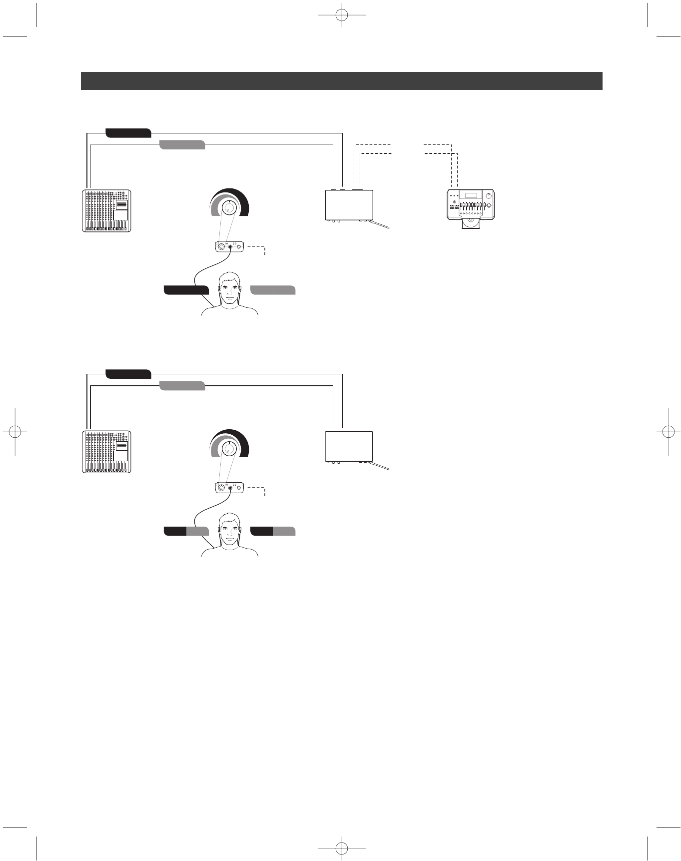
Stereo setup. See image A on page 10.
Basic stereo setup
1. Inside the M2R Stereo Receiver:
Set DIP switch 2 to STEREO Output (Down);
Set DIP switch 4 to STEREO Mode (Down). (See page 7)
2. Create separate left and right band mixes using two aux channels
from your mixing console.
3. Connect one of these aux outputs from your mixing console to the
L/1 input on your M2T Stereo Transmitter; connect the second aux
output from your mixer to the R/2 input on your M2T Stereo
Transmitter.
4. Monitor the LED indicators on front of transmitter to make certain
signal is not clipping. (Signal is clipped when the peak light is on
constantly.)
5. If necessary, use the trim control to adjust input level.
6. Use the balance control on your M2R Stereo Receiver to control
the left/right stereo image. (Turn the balance control to the left to hear
more of L/1; turn the balance control to the right to hear more of R/2.)
7. Adjust volume control to a comfortable, safe level. Note: Use
volume levels as low as possible.
8. (Optional). Use M2T Stereo Transmitter’s loop output to connect
L/1 and R/2 to a recording device.
9. (Optional). Insert optional Audio-Technica lavalier microphone
(available separately) into M2R Stereo Receiver to increase
awareness of ambient sound.
10. Any number of additional M2R Stereo Receivers can be set to the
same frequency and receive the same mix.
Personal Mix Control. See image B on page 10.
Typical two-channel operation using Personal Mix Control
1. Inside the M2R Stereo Receiver:
Set DIP switch 2 to MIX Ouput (Up);
Set DIP switch 4 to STEREO Mode (Down).
2. Create a band mix with an aux channel of your mixing console.
3. On a separate aux channel of your mixing console, create a second
mix featuring vocals. (Alternatively, this second mix could feature
guitars, drums, keyboards, etc.)
4. Connect the band mix aux output to the L/1 input on your M2T
Stereo Transmitter.
5. Connect the vocal mix aux output to the R/2 input on your M2T
Stereo Transmitter.
6. Monitor the LED indicators on front of transmitter to make certain
the signal is not clipping. (Signal is clipped when the peak light is
on constantly or distortion is heard.)
7. If necessary, use the trim control to adjust input level.
8. Turn the M2R Stereo Receiver’s balance control toward the left to
hear more vocal (L/1) in both ears; turn the receiver’s balance
control to the right to hear more band (R/2) in both ears.
9. (Optional). Use M2T Stereo Transmitter’s loop output to connect
L/1 and R/2 to a recording device.
10. (Optional). Insert optional Audio-Technica lavalier microphone
(available separately) into M2R Stereo Receiver to increase
awareness of ambient sound.
11. (Optional). Connect click source (for drummers) to your belt
pack’s Aux Input.
12. Any number of additional M2R Stereo Receivers can be set to the
same frequency and receive the same mix.
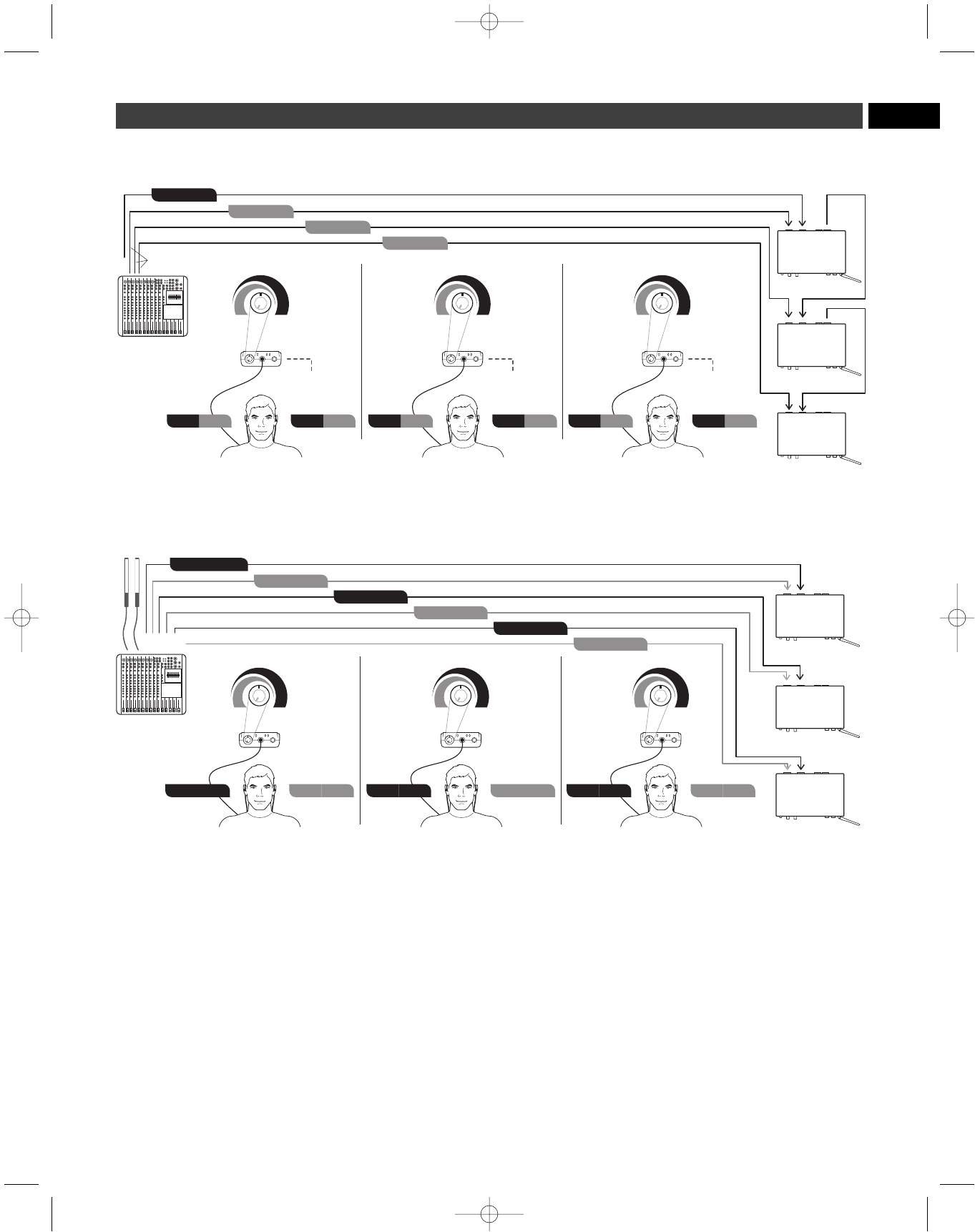
Advanced two-channel setup (Personal Mix Control) Using direct
outputs and multiple M2 systems. See image C on page 11.
Inside the M2R Stereo Receiver:
Set M2R Stereo Receiver DIP switch 2 to MIX Ouput (Up);
Set M2R Stereo Receiver DIP switch 4 to STEREO Mode (Down).
This setup enables each individual band member to control his/her
relative mix levels using the balance control on his/her M2R Stereo
Receiver. Turn the M2R Stereo Receiver’s balance control toward the
left to hear more vocal or instrument of choice level (L/1) in both ears;
turn the receiver’s balance control to the right to hear more band, (R/2)
in both ears.
Advanced two-channel stereo setup. See image D on page 11.
Multiple auxiliary sends and ambient audience microphones
Note: Do not feed ambient microphones to main output of PA.
This setup enables you to create custom stereo mixes for each band
member using individual auxiliary outputs and IEM systems for each
band member.
P52001_M2-System_OM 2/13/08 4:16 PM Page 9
10
) ) )
MIXER
Band Mix
Vocals
Left
(More Vocals)
M2R
Right
(More Band Mix)
AMBIENT MICROPHONE
(optional)
Band + Vocals Band + Vocals
( ( (
M2T
Input L/1
Input R/2
) ) )
MIXER
Band Mix Right
Band Mix Left
Left
M2R
Right
AMBIENT MICROPHONE
(optional)
Band Mix Right Band Mix Left
( ( (
M2T
Input L/1
Input R/2
Loop Out L/1
Loop Out R/2
RECORDING DEVICE
(optional)
B. Typical 2 Channel Set-up (Personal Mix Control)
A. Basic Stereo Set-up
P52001_M2-System_OM 2/13/08 4:16 PM Page 10
11 EN
) ) )
MIXER
Band Mix
Vocal 1
Vocal 2
Guitar
Left
(More Vocal 1)
M2R
Right
(More Band Mix)
SYSTEM 1
AMBIENT MICROPHONE
(optional)
Band + Vocal 1 Band + Vocal 1
( ( ( ) ) )
( ( (
Left
(More Guitar)
M2R
Right
(More Band Mix)
SYSTEM 3
AMBIENT MICROPHONE
(optional)
Band + Guitar
( ( ( Band + Guitar
) ) )
Left
(More Vocal 2)
M2R
Right
(More Band Mix)
SYSTEM 2
AMBIENT MICROPHONE
(optional)
M2T (SYSTEM 2)
M2T (SYSTEM 3)
M2T (SYSTEM 1)
Input L/1
Input R/2
Loop Out L/1
Loop Out R/2
Input L/1
Input R/2
Loop Out L/1
Loop Out R/2
Input L/1
Input R/2
Loop Out L/1
Loop Out R/2
Band + Vocal 2 Band + Vocal 2
C. Advanced 2 Channel Set-up (Personal Mix Control Using Direct Outputs)
Aux
Direct Outputs
M2T CUSTOM MIX 2
(SYSTEM 2)
M2T CUSTOM MIX 3
(SYSTEM 3)
M2T CUSTOM MIX 1
(SYSTEM 1)
AMBIENT
MICROPHONES
) ) )
MIXER
Custom Mix 1 Right
Custom Mix 1 Left
Left
M2R
Right
SYSTEM 1
Custom Mix 1 Right Custom Mix 1 Left
( ( ( ) ) )
( ( (
Left
M2R
Right
SYSTEM 3
( ( ( ) ) )
Left
M2R
Right
SYSTEM 2
Input L/1
Input R/2
Input L/1
Input R/2
Input L/1
Input R/2
D. Advanced 2 Channel Stereo Set-up Multiple Aux Sends and Ambient Audience Mics
Custom Mix 2 Right Custom Mix 2 Left Custom Mix 3 Right Custom Mix 3 Left
Custom Mix 2 Right
Custom Mix 2 Left
Custom Mix 3 Right
Custom Mix 3 Left
Aux 1
Aux 2
Aux 3
Aux 4
Aux 5
Aux 6
P52001_M2-System_OM 2/13/08 4:16 PM Page 11
12
Specifications†
Overall System
UHF Operating Frequencies
Band Frequency Range Number of Frequencies
Band E: 790.000 to 822.000 MHz 100
Band F: 832.000 to 865.000 MHz 100
Band L: 575.000 to 608.000 MHz 100
Band M: 614.000 to 647.000 MHz 100
Not all frequency bands available in all areas.
Please check with local regulations.
Minimum Frequency Step 25 kHz
Modulation Mode FM stereo
Maximum Deviation ±40 kHz
Dynamic Range 90 dB (typical), A-weighted
Total Harmonic Distortion <1% (at 1 kHz, ±20 kHz Deviation)
Operating Range 100 m (300'), typical
Open range environment with no interfering signals.
Operating Temperature Range -5° C (23° F) to 50° C (122° F)
Battery performance may be reduced at very low temperatures.
Frequency Response 60 Hz to 13 kHz (±3 dB)
Simultaneous Use 10 channels per band (maximum recommended)
For assistance with multi-band operation or other frequency
coordination issues, please contact your regional
Audio-Technica customer service representitive.
Receiver
Receiving System Double conversion superheterodyne
RF Sensitivity 20 dBuV (at 60 dB S/N ratio, 50 ohms termination)
Headphone Output Connector 3.5 mm TRS stereo phone jack
Headphone Output Power 65 mW (at 32 ohms)
Antenna Input SMA-type, 50 ohms
Aux Input Connector 3.5 mm TRS stereo phone jack
Batteries 2 x 1.5V AA (not included)
Battery Life 8 hours (alkaline)
Depending on battery type and use pattern
Dimensions 70.0 mm (2.76") W x 25.0 mm (0.98") D x 110.0 mm (4.33") H
Net Weight 110 g (3.9 oz), without batteries
Accessories Included EP3 earphones; frequency sticker; flexible antenna
Transmitter
RF Power Output 10 mW/30 mW (switchable), 50 ohms
Limited to 10 mW within 863 MHz to 865 MHz.
Following national regulations.
Spurious Emissions Following federal and national regulations
Input Connection XLRF-type/6.3 mm stereo (1/4") combination connector
Pin 1 and Sleeve: Ground
Pin 2 and Tip: Hot
Pin 3 and Ring: Cold
Maximum Input Level XLRF-type/6.3 mm stereo (1/4"), balanced: +26 dBu
6.3 mm (1/4") mono, unbalanced: +26 dBu
Loop Output Connection XLRM-type connector
Pin 1: Ground
Pin 2: Hot
Pin 3: Cold
Power Requirement 12-18V DC, 600 mA
Antenna Attached whip
Dimensions 210.0 mm (8.30") W x 132.0 mm (5.20") D x 44.0 mm (1.70") H
Net Weight 870 g (30.7 oz.), without accessories
Accessories Included AC adapter (country dependant); rack-mount adapters
† Specifications are subject to change without notice.
P52001_M2-System_OM 2/13/08 4:16 PM Page 12
13 EN
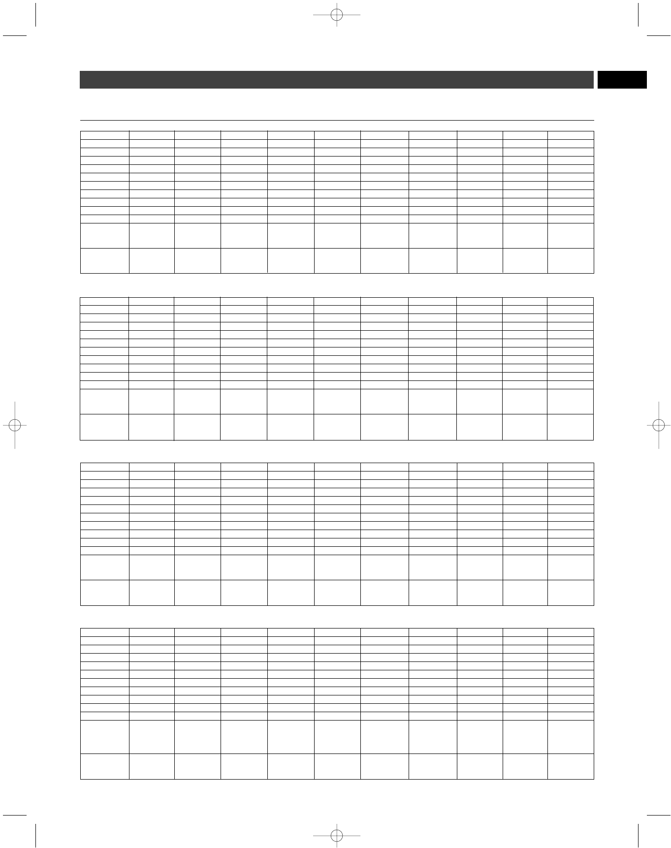
M-Band GroupA GroupB GroupC GroupD GroupE GroupF GroupG GroupH GroupI GroupJ
CH-1 615.125 614.000 614.500 615.875 616.750 614.750 614.875 614.125 614.250 616.625
CH-2 619.625 619.500 619.500 619.625 617.750 618.750 615.625 621.125 617.625 617.125
CH-3 621.375 622.000 626.125 620.375 622.625 621.000 620.500 622.375 622.250 618.875
CH-4 624.375 623.125 632.375 622.375 624.500 631.250 624.125 628.625 623.875 623.875
CH-5 630.875 628.250 634.375 630.625 629.625 633.750 626.875 629.625 631.125 626.875
CH-6 632.375 629.125 641.500 633.625 632.625 635.750 629.250 636.375 632.500 633.375
CH-7 639.875 639.500 642.000 640.375 642.250 642.500 637.125 640.625 636.625 640.875
CH-8 642.625 642.250 644.500 642.125 643.000 643.500 641.500 642.375 642.500 641.875
CH-9 644.875 644.000 645.500 643.625 646.625 645.250 643.125 645.625 643.625 645.375
CH-10 646.875 647.000 646.250 646.125 646.875 646.750 644.500 646.375 644.375 646.625
Used U.S.
TV - 38, 39, 40, 38, 39, 40, 38, 39, 40, 38, 39, 40, 38, 39, 40, 38, 39, 40, 38, 39, 40, 38, 39, 40, 38, 39, 40, 38, 39, 40,
Channels 41, 42, 43 41, 42, 43 41, 42, 43 41, 42, 43 41, 42, 43 41, 42, 43 41, 42, 43 41, 42, 43 41, 42, 43 41, 42, 43
Used
European 39, 40, 41, 39, 40, 41, 39, 40, 41, 39, 40, 41, 39, 40, 41, 39, 40, 41, 39, 40, 41, 39, 40, 41, 39, 40, 41, 39, 40, 41,
TV-Channels 42, 43 42, 43 42, 43 42, 43 42, 43 42, 43 42, 43 42, 43 42, 43 42, 43
M2 Frequency Plans
L-Band GroupA GroupB GroupC GroupD GroupE GroupF GroupG GroupH GroupI GroupJ
CH-1 576.125 575.000 575.500 576.875 577.750 575.750 575.875 575.125 575.250 577.625
CH-2 580.625 580.500 580.500 580.625 578.750 579.750 576.625 582.125 578.625 578.125
CH-3 582.375 583.000 587.125 581.375 583.625 582.000 581.500 583.375 583.250 579.875
CH-4 585.375 584.125 593.375 583.375 585.500 592.250 585.125 589.625 584.875 584.875
CH-5 591.875 589.250 595.375 591.625 590.625 594.750 587.875 590.625 592.125 587.875
CH-6 593.375 590.125 602.500 594.625 593.625 596.750 590.250 597.375 593.500 594.375
CH-7 600.875 600.500 603.000 601.375 603.250 603.500 598.125 601.625 597.625 601.875
CH-8 603.625 603.250 605.500 603.125 604.000 604.500 602.500 603.375 603.500 602.875
CH-9 605.875 605.000 606.500 604.625 607.625 606.250 604.125 606.625 604.625 606.375
CH-10 607.875 608.000 607.250 607.125 607.875 607.750 605.500 607.375 605.375 607.625
Used U.S.
TV - 31, 32, 33, 31, 32, 33, 31, 32, 33, 31, 32, 33, 31, 32, 33, 31, 32, 33, 31, 32, 33, 31, 32, 33, 31, 32, 33, 31, 32, 33,
Channels 34, 35, 36 34, 35, 36 34, 35, 36 34, 35, 36 34, 35, 36 34, 35, 36 34, 35, 36 34, 35, 36 34, 35, 36 34, 35, 36
Used
European 34, 35, 36, 34, 35, 36, 34, 35, 36, 34, 35, 36, 34, 35, 36, 34, 35, 36, 34, 35, 36, 34, 35, 36, 34, 35, 36, 34, 35, 36,
TV-Channels 37, 38 37, 38 37, 38 37, 38 37, 38 37, 38 37, 38 37, 38 37, 38 37, 38
E-Band GroupA GroupB GroupC GroupD GroupE GroupF GroupG GroupH GroupI GroupJ
CH-1 790.850 790.300 790.100 790.750 790.100 790.300 790.100 800.100 806.125 790.000
CH-2 792.525 790.700 790.600 791.250 790.500 791.000 790.500 800.350 806.375 790.250
CH-3 793.925 791.950 792.050 792.500 792.025 792.975 792.750 801.100 807.125 791.000
CH-4 797.750 796.150 794.425 794.500 794.225 796.000 796.425 803.350 810.650 793.250
CH-5 798.850 798.700 797.500 801.250 797.300 802.775 800.750 811.900 812.150 795.250
CH-6 809.175 806.300 808.050 807.750 802.975 805.100 805.400 813.900 813.400 796.750
CH-7 811.100 809.775 812.950 812.250 813.300 813.900 810.675 815.400 813.900 801.500
CH-8 813.300 812.625 813.900 815.250 818.225 818.025 812.425 818.150 792.000 804.250
CH-9 813.800 813.600 797.900 819.250 820.900 821.500 813.900 819.400 794.325 805.500
CH-10 810.325 792.950 809.325 819.500 821.700 821.900 791.750 819.900 797.325 806.000
Notes: German German German French French French German 800.100 channel 63 channel 61+
user user user series 1 series 2 series 3 user 819.900 focus 62 only
group d) group cc) group b) group a)
German German German German
musicians rental private public
companies broadcasters broadcasters
F-Band GroupA GroupB GroupC GroupD GroupE GroupF GroupG GroupH GroupI GroupJ
CH-1 854.900 863.100 838.850 838.300 838.100 838.100 832.000 832.500 832.000 863.125
CH-2 855.275 863.500 840.525 838.700 838.600 838.500 832.250 832.750 832.250 863.375
CH-3 856.575 864.900 841.925 839.950 840.050 840.750 833.000 833.500 833.000 864.900
CH-4 857.625 854.125 845.750 844.150 842.425 844.425 835.250 836.500 835.250 832.000
CH-5 860.900 854.775 846.850 846.700 845.500 848.750 837.250 840.750 837.250 832.500
CH-6 861.550 856.825 857.175 854.300 856.050 853.400 838.750 843.250 854.000 833.250
CH-7 864.550 857.975 859.100 857.775 860.950 858.675 844.250 856.250 857.500 836.050
CH-8 838.025 838.375 861.300 860.625 861.900 860.425 851.500 858.500 860.250 839.100
CH-9 839.950 839.275 861.800 861.600 845.900 861.900 857.500 859.750 861.500 853.000
CH-10 838.275 842.725 858.325 840.950 857.325 839.750 860.250 861.250 862.000 858.575
UK shared deregulated+ German German German German Fullrange Fullrange2 66 + 69 deregulated
frequencies 69 (Spain) user user user user first first
+ch 67 use UK indoor group d) group cc) group b) group a)
for Dutch Dutch ch 67
German German German German
musicians retail private public
companies broadcasters broadcasters
P52001_M2-System_OM 2/13/08 4:16 PM Page 13