Autel Intelligent Tech 1610MX808 Professional scan tool User Manual
Autel Intelligent Tech. Corp., Ltd. Professional scan tool
UserManual.wiki
>
Autel Intelligent Tech
>
1610MX808 User Manual
User manual
Navigation menu
Upload a User Manual
Namespaces
Wiki Guide
HTML
PDF
Info
Views
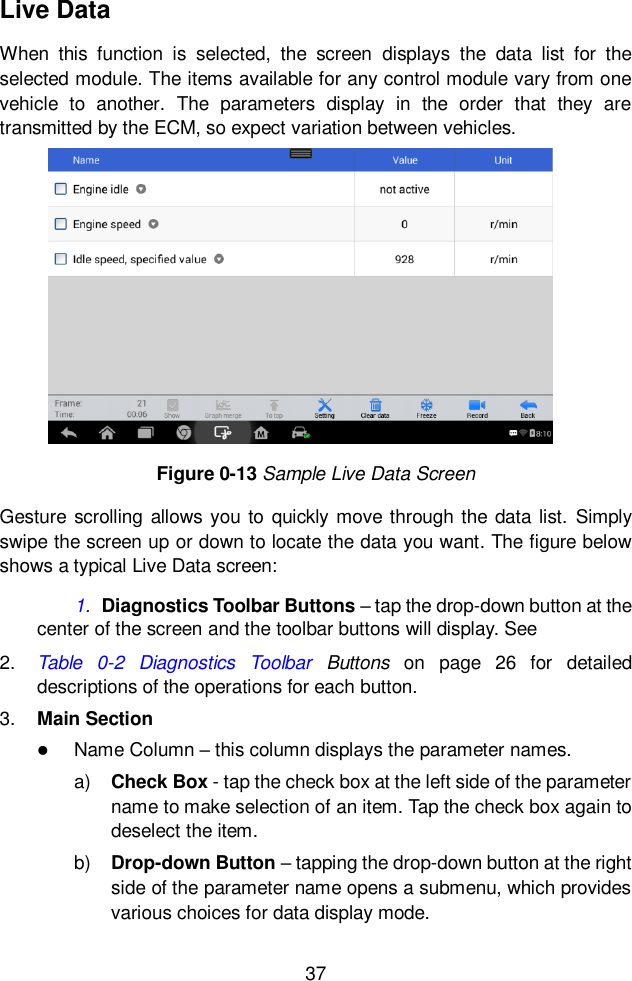
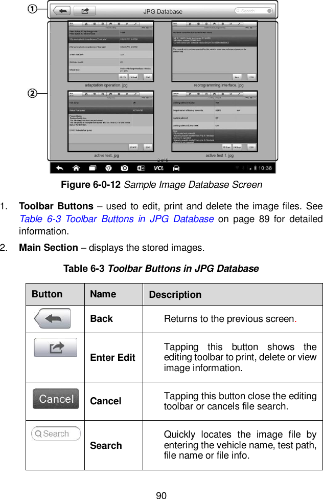
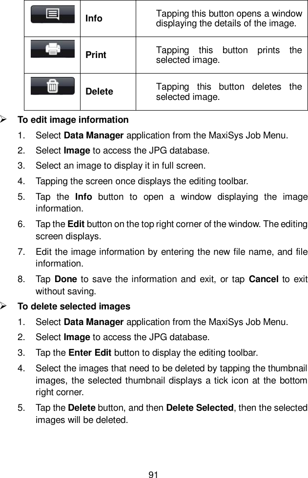
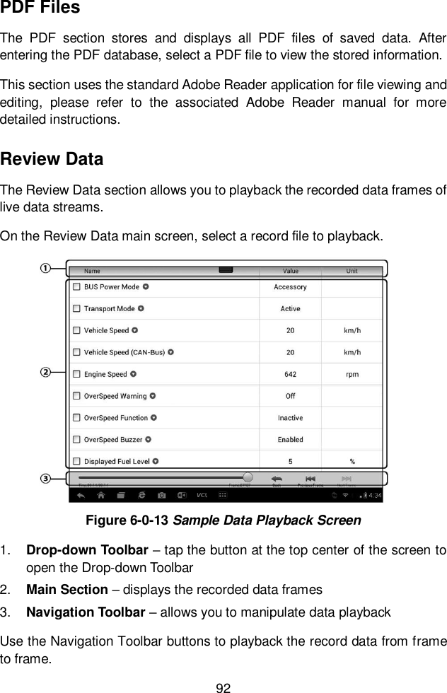
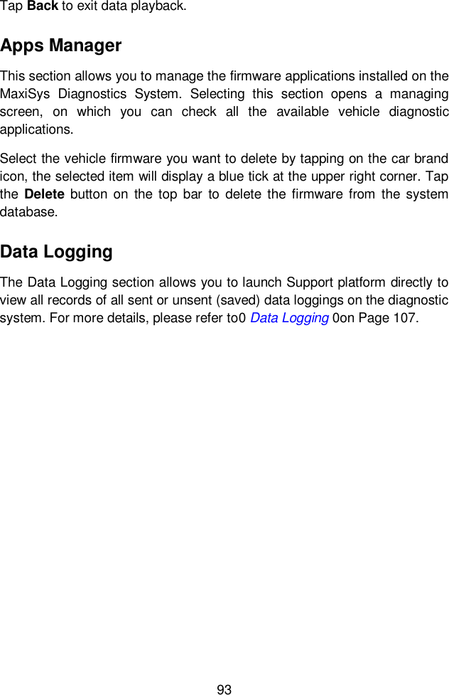
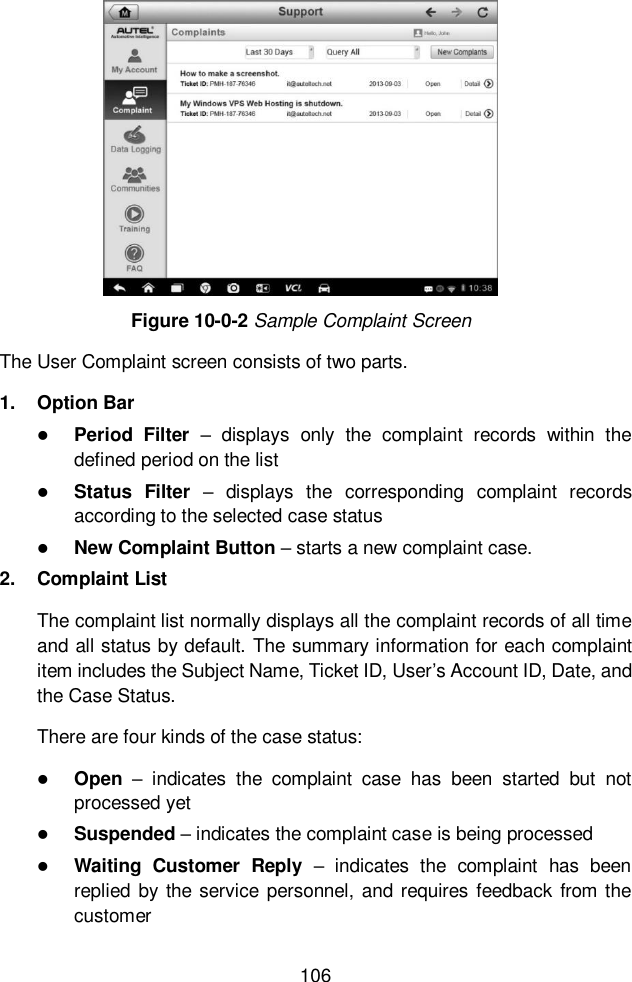
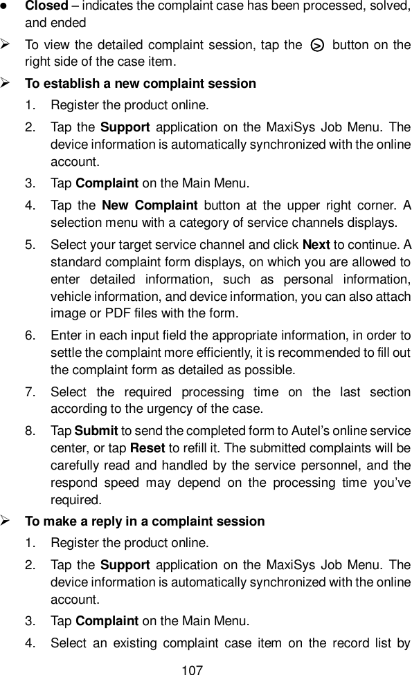
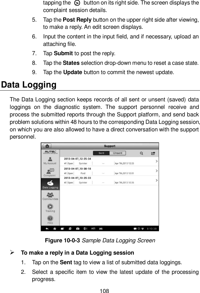
User Manual
Discussion / Help
Navigation