Autel Intelligent Tech 2017MAXIAP Wireless Diagnostic Interface User Manual
Autel Intelligent Tech. Corp., Ltd. Wireless Diagnostic Interface
UserManual.wiki
>
Autel Intelligent Tech
>
2017MAXIAP User Manual
User manual
Navigation menu
Upload a User Manual
Namespaces
Wiki Guide
HTML
PDF
Info
Views
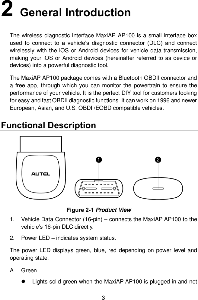
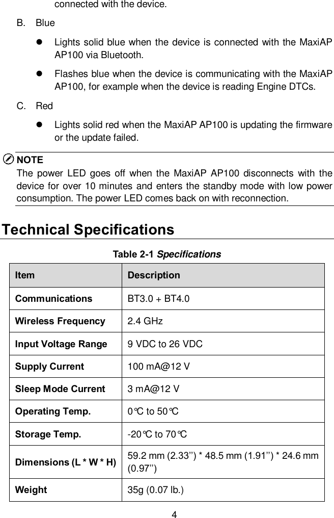
User Manual
Discussion / Help
Navigation