Autel Intelligent Tech 2017MAXIAP Wireless Diagnostic Interface User Manual
Autel Intelligent Tech. Corp., Ltd. Wireless Diagnostic Interface
User manual

i
Trademarks
Autel®, MaxiSys®, MaxiDAS®, MaxiScan®, MaxiCheck®, MaxiRecorder®,
and MaxiCheck® are trademarks of Autel Intelligent Technology Corp., Ltd.,
registered in China, the United States and other countries. All other marks
are trademarks or registered trademarks of their respective holders.
Copyright Information
No part of this manual may be reproduced, stored in a retrieval system or
transmitted, in any form or by any means, electronic, mechanical,
photocopying, recording, or otherwise without the prior written permission
of Autel.
Disclaimer of Warranties and Limitation of Liabilities
All information, specifications and illustrations in this manual are based on
the latest information available at the time of printing.
Autel reserves the right to make changes at any time without notice. While
information of this manual has been carefully checked for accuracy, no
guarantee is given for the completeness and correctness of the contents,
including but not limited to the product specifications, functions, and
illustrations.
Autel will not be liable for any direct, special, incidental, indirect damages or
any economic consequential damages (including the loss of profits).
IMPORTANT
Before operating or maintaining this unit, please read this manual carefully,
paying extra attention to the safety warnings and precautions.
For Services and Support
pro.autel.com
www.autel.com
1-855-288-3587/1-855-AUTELUS (North America)
0086-755-86147779 (China)
support@autel.com
For technical assistance in all other markets, please refer to Service and
Support section in this manual.

ii
Safety Information
For your own safety and the safety of others, and to prevent damage to the
device and vehicles upon which it is used, it is important that the safety
instructions presented throughout this manual be read and understood by
all persons operating or coming into contact with the device.
There are various procedures, techniques, tools, and parts for servicing
vehicles, as well as in the skill of the person doing the work. Because of the
vast number of test applications and variations in the products that can be
tested with this equipment, we cannot possibly anticipate or provide advice
or safety messages to cover every circumstance. It is the automotive
technician’s responsibility to be knowledgeable of the system being tested.
It is crucial to use proper service methods and test procedures. It is essential
to perform tests in an appropriate and acceptable manner that does not
endanger your safety, the safety of others in the work area, the device being
used, or the vehicle being tested.
Before using the device, always refer to and follow the safety messages and
applicable test procedures provided by the manufacturer of the vehicle or
equipment being tested. Use the device only as described in this manual.
Read, understand, and follow all safety messages and instructions in this
manual.
Safety Messages
Safety messages are provided to help prevent personal injury and
equipment damage. All safety messages are introduced by a signal word
indicating the hazard level.
DANGER
Indicates an imminently hazardous situation which, if not avoided, will result
in death or serious injury to the operator or to bystanders.
WARNING
Indicates a potentially hazardous situation which, if not avoided, could result
in death or serious injury to the operator or to bystanders.

iii
Safety Instructions
The safety messages herein cover situations Autel is aware of. Autel cannot
know, evaluate or advise you as to all of the possible hazards. You must be
certain that any condition or service procedure encountered does not
jeopardize your personal safety.
DANGER
When an engine is operating, keep the service area WELL VENTILATED or
attach a building exhaust removal system to the engine exhaust system.
Engines produce carbon monoxide, an odorless, poisonous gas that causes
slower reaction time and can lead to serious personal injury or loss of life.
SAFETY WARNINGS
Always perform automotive testing in a safe environment.
Wear safety eye protection that meets ANSI standards.
Keep clothing, hair, hands, tools, test equipment, etc. away from all
moving or hot engine parts.
Operate the vehicle in a well-ventilated work area, for exhaust gases
are poisonous.
Put the transmission in PARK (for automatic transmission) or
NEUTRAL (for manual transmission) and make sure the parking brake
is engaged.
Put blocks in front of the drive wheels and never leave the vehicle
unattended while testing.
Be extra cautious when working around the ignition coil, distributor cap,
ignition wires and spark plugs. These components create hazardous
voltages when the engine is running.
Keep a fire extinguisher suitable for gasoline, chemical, and electrical
fires nearby.
Do not connect or disconnect any test equipment while the ignition is
on or the engine is running.
Keep the test equipment dry, clean, free from oil, water or grease. Use
a mild detergent on a clean cloth to clean the outside of the equipment
as necessary.
Do not drive the vehicle and operate the test equipment at the same
iv
time. Any distraction may cause an accident.
Refer to the service manual for the vehicle being serviced and adhere
to all diagnostic procedures and precautions. Failure to do so may
result in personal injury or damage to the test equipment.
To avoid damaging the test equipment or generating false data, make
sure the vehicle battery is fully charged and the connection to the
vehicle DLC is clean and secure.
Do not place the test equipment on the distributor of the vehicle. Strong
electro-magnetic interference can damage the equipment.
v
CONTENTS
1 USING THIS MANUAL ........................................................................... 1
CONVENTIONS ......................................................................................... 1
Bold Text ........................................................................................... 1
Notes and Important Messages .......................................................... 1
Hyperlink............................................................................................ 2
Illustrations ........................................................................................ 2
2 GENERAL INTRODUCTION .................................................................. 3
FUNCTIONAL DESCRIPTION ......................................................................... 3
TECHNICAL SPECIFICATIONS ....................................................................... 4
WIRELESS COMMUNICATION ....................................................................... 5
POWER SOURCE ...................................................................................... 5
3 GETTING STARTED ............................................................................. 6
POWERING UP ......................................................................................... 6
APPLICATION BUTTONS.............................................................................. 8
NAVIGATION BUTTONS ............................................................................... 8
4 READ DTCS ........................................................................................ 10
5 CLEAR DTCS ...................................................................................... 11
6 REPAIR REPORTS ............................................................................. 12
7 SMOG CHECK .................................................................................... 13
8 MODE 6 .............................................................................................. 15
9 FREEZE FRAME ................................................................................. 16
10 VEHICLE INFO .................................................................................... 17
11 MIL STATUS ....................................................................................... 18
12 LIVE DATA .......................................................................................... 19
13 ME ...................................................................................................... 20
REGISTER ............................................................................................. 20
LOG IN .................................................................................................. 20
ONLINE PURCHASE.................................................................................. 21
REPAIR REPORTS ................................................................................... 21
vi
VCI MANAGEMENT ................................................................................. 21
SETTINGS .............................................................................................. 22
Device Activate ................................................................................ 23
Firmware Update.............................................................................. 24
Unit .................................................................................................. 24
Software Update .............................................................................. 24
About ............................................................................................... 25
14 PRODUCT TROUBLESHOOTING ....................................................... 26
VEHICLE LINKING ERROR ......................................................................... 26
15 COMPLIANCE INFORMATION ............................................................ 27
16 WARRANTY AND SERVICE ................................................................ 29
LIMITED ONE YEAR WARRANTY ................................................................ 29
SERVICE AND SUPPORT ........................................................................... 30

1
1 Using This Manual
This manual contains device usage instructions.
Some illustrations shown in this manual may contain modules and optional
equipment that are not included in your system. Contact your sales
representative for availability of other modules and optional tools or
accessories.
Conventions
The following conventions are used.
Bold Text
Bold text is used to highlight selectable items such as buttons and menu
options.
Example:
Tap OK.
Notes and Important Messages
Notes
A NOTE provides helpful information such as additional explanations, tips,
and comments.
Example:
NOTE
New batteries reach full capacity after approximately 3 to 5 charging and
discharging cycles.

2
Important
IMPORTANT indicates a situation which, if not avoided, may result in
damage to the test equipment or vehicle.
Example:
IMPORTANT
Keep the cable away from heat, oil, sharp edges and moving parts. Replace
damaged cables immediately.
Hyperlink
Hyperlinks, or links, that take you to other related articles, procedures, and
illustrations are available in electronic documents. Blue italic text indicates
a selectable hyperlink and blue underlined text indicates a website link or
an email address link.
Illustrations
Illustrations used in this manual are samples, the actual testing screen may
vary for each vehicle being tested. Observe the menu titles and on-screen
instructions to make correct option selection.
3
2 General Introduction
The wireless diagnostic interface MaxiAP AP100 is a small interface box
used to connect to a vehicle’s diagnostic connector (DLC) and connect
wirelessly with the iOS or Android devices for vehicle data transmission,
making your iOS or Android devices (hereinafter referred to as device or
devices) into a powerful diagnostic tool.
The MaxiAP AP100 package comes with a Bluetooth OBDII connector and
a free app, through which you can monitor the powertrain to ensure the
performance of your vehicle. It is the perfect DIY tool for customers looking
for easy and fast OBDII diagnostic functions. It can work on 1996 and newer
European, Asian, and U.S. OBDII/EOBD compatible vehicles.
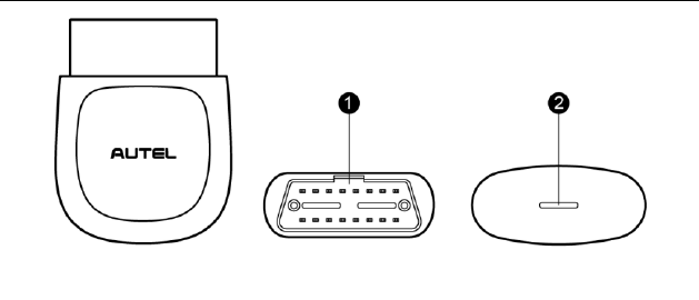
Functional Description
1. Vehicle Data Connector (16-pin) – connects the MaxiAP AP100 to the
vehicle’s 16-pin DLC directly.
2. Power LED – indicates system status.
The power LED displays green, blue, red depending on power level and
operating state.
A. Green
Lights solid green when the MaxiAP AP100 is plugged in and not
Figure 2-1 Product View
4
connected with the device.
B. Blue
Lights solid blue when the device is connected with the MaxiAP
AP100 via Bluetooth.
Flashes blue when the device is communicating with the MaxiAP
AP100, for example when the device is reading Engine DTCs.
C. Red
Lights solid red when the MaxiAP AP100 is updating the firmware
or the update failed.
NOTE
The power LED goes off when the MaxiAP AP100 disconnects with the
device for over 10 minutes and enters the standby mode with low power
consumption. The power LED comes back on with reconnection.
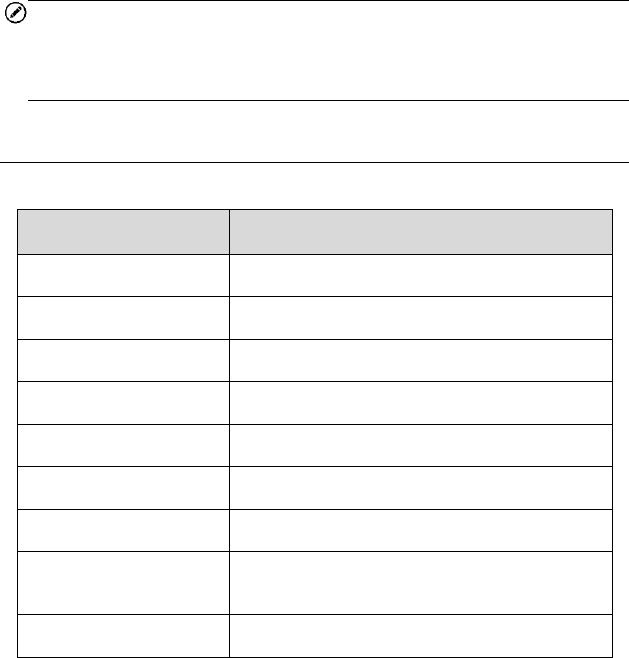
Technical Specifications
Table 2-1 Specifications
Item
Description
Communications
BT3.0 + BT4.0
Wireless Frequency
2.4 GHz
Input Voltage Range
9 VDC to 26 VDC
Supply Current
100 mA@12 V
Sleep Mode Current
3 mA@12 V
Operating Temp.
0°C to 50°C
Storage Temp.
-20°C to 70°C
Dimensions (L * W * H)
59.2 mm (2.33’’) * 48.5 mm (1.91’’) * 24.6 mm
(0.97’’)
Weight
35g (0.07 lb.)

5
Wireless Communication
The MaxiAP AP100 supports BT communication. It can transmit vehicle
data to your iOS or Android devices without a physical connection. The
working range for BT communication is about 33 feet (about 10 m). A signal
lost due to moving out of range automatically restores itself when the device
is brought closer to the MaxiAP AP100 connector.
Power Source
The MaxiAP AP100 operates on 12-volt vehicle power, which it receives
through the vehicle data connection port. The unit powers on whenever it is
connected to an OBDII/ EOBD compliant data link connector (DLC).
6
3 Getting Started
NOTE
The images and illustrations depicted in this manual may differ from the
actual ones. The user interface for iOS & Android devices might be slightly
different.
Powering Up
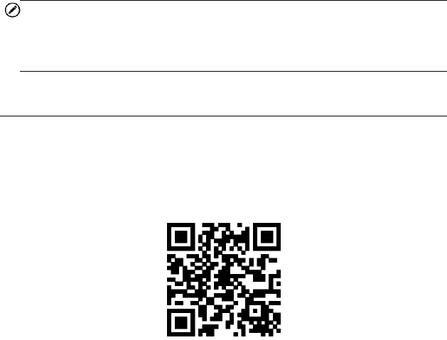
1. Download & installation
Search for MaxiAP from App Store or Google Play to download
and install to your device.
Or scan the QR code to download the MaxiAP AP100 app.
2. Register & login
Open the MaxiAP app and select Connect later.
Tap Me at the bottom and then tap Register. Follow the on-screen
instructions to complete the registration.
Log in with the email address & password you registered.
3. Plug the MaxiAP AP100 connector into the test vehicle’s DLC (Data
Link Connector).
The vehicle’s DLC is generally located under the vehicle dash.
4. Turn ignition to Key On, Engine Off position. The LED on MaxiAP
AP100 lights solid green.
7
5. VCI Connection
Tap Me>VCI Management or the VCI button on the top left of the Home
screen to enter the VCI Management screen. Tap the Bluetooth name
of the MaxiAP AP100 and pair up with the device. The Bluetooth name
starts with AP followed by the MaxiAP AP100’s serial number.
Turn on the device’s Bluetooth beforehand for connection.
When the device is successfully paired up and communicating with
the MaxiAP AP100, the LED on the MaxiAP AP100 lights solid blue.
Tap Done on the VCI Management screen to return to Home
screen.
6. Tap Me>Settings>Device Activate in the app to activate the device.
7. Your MaxiAP AP100 is now ready to work.
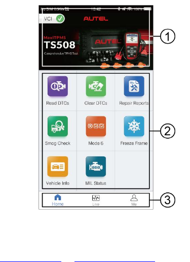
① Dynamic Rotation Banner – information about other popular Autel
products, tap the picture to visit the product page on Autel websites,
www.autel.com or www.maxitpms.com.
② Application Buttons
Figure 3-1 Sample MaxiAP Job Menu
8
③ Navigation Buttons
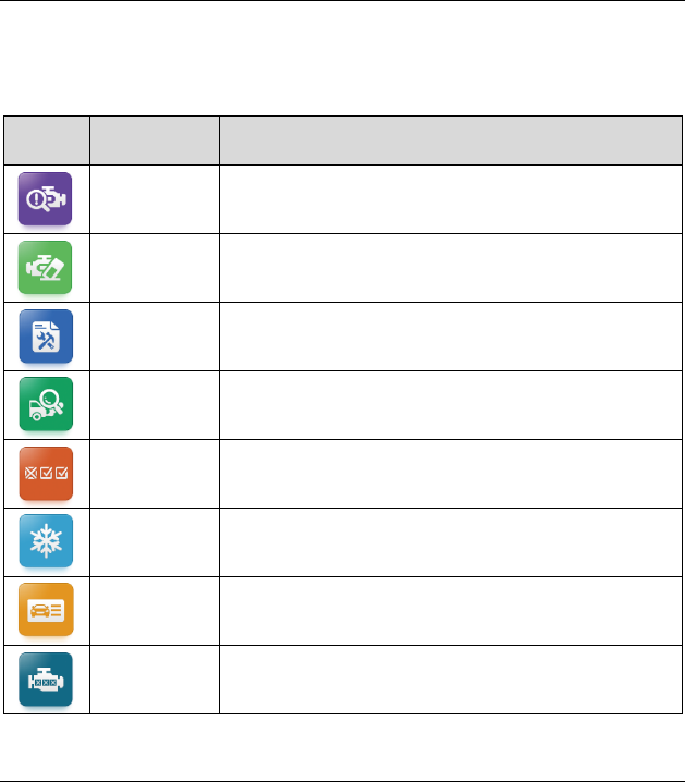
Application Buttons
The table below briefly describes each of the applications in the MaxiAP
system.
Table 3-1 Applications
Button
Name
Description
Read DTCs
Reads the diagnostic trouble codes. See Read
DTCs on page 10.
Clear DTCs
Clears the diagnostic trouble codes. See Clear
DTCs on page 11.
Repair
Reports
Generates repair reports for test vehicles. See
Repair Reports on page 12.
Smog
Check
Checks the readiness of the monitoring system.
See Smog Check on page 13.
Mode 6
Views the results of On-Board Monitor tests. See
Mode 6 on page 13.
Freeze
Frame
Snapshot of the critical parameter values when the
DTC is set. See Freeze Frame on page 16.
Vehicle
Info
Displays the VIN, CVN and other information of the
test vehicle. See Vehicle Info on page 17.
MIL Status
Checks the status of the MIL and other additional
information. See MIL Status on page 18.
Navigation Buttons
Operations of the Navigation buttons at the bottom of the screen are
described in the table below:
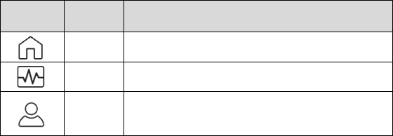
9
Table 3-2 Navigation Buttons
Button
Name
Description
Home
Returns to the Home screen.
Live
Displays system live data.
Me
Personal center for register, log in, settings,
etc.
10
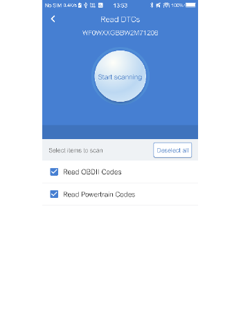
4 Read DTCs
This option can read and clear pending, stored, permanent codes for 1996
and newer European, Asian, and U.S. OBDII/EOBD compatible vehicles.
It can also read and clear enhanced codes for engine and transmission
systems of GM, Chrysler, and Ford vehicles. The vehicle coverage and
available modules will be increased with regular software update.
Tap > to view the details of a specific DTC (Diagnostic Trouble Codes). At
the bottom of the DTC Details screen, you can also tap the Previous or
Next button to view the details of the previous/next DTC. Or you can tap the
snowflake button at the bottom middle to view the freeze frame of the
specific DTC if the freeze frame is available.
Figure 4-1 Sample Read DTCs Screen
11
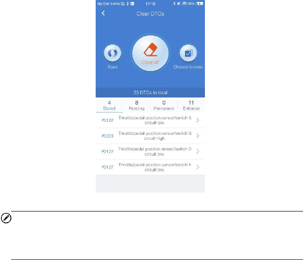
5 Clear DTCs
There are two ways to clear trouble codes.
1. Tap Read DTCs, when the scan completes, tap Clear on the top and
pick the codes you want to clear. You can clear Engine codes, ABS
codes or both at the same time. Wait for codes to be cleared.
2. Clear codes directly from the Home screen without having to read
codes first. Again, you can clear Engine codes, ABS codes or both at
the same time. Now, wait for codes to be cleared.
In the Clear DTCs screen, you can tap Clear all or Choose to clear. Please
be reminded that this action will erase the DTCs and turn off MIL, but the
problems are still there.
NOTE
Most vehicles can have codes cleared with the engine running. However,
some vehicles such as doge require the engine to be off with the key in the
ACC position to clear codes.
Figure 5-1 Sample Clear DTCs Screen
12
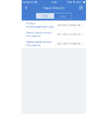
6 Repair Reports
The MaxiAP app automatically saves a repair report for each diagnostic
session that can tell you what is wrong with your vehicle. Based on the
trouble codes in the specific vehicle, a repair report contains the definition
of the DTCs (stored codes, pending codes, permanent codes and
manufacture-specific codes) and possible causes. It can also generate a
pdf file for easy viewing, sharing, and printing.
To create a repair report, tap Read DTCs, tap i next to a trouble code on
iOS devices or > on Android devices. Now the repair report is saved under
Saved Reports on the Home screen for future reference.
Figure 6-1 Sample Repair Reports Screen
13
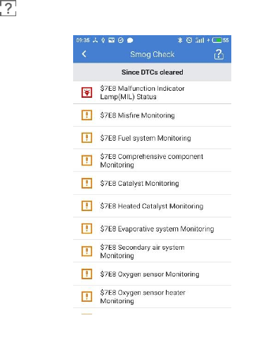
7 Smog Check
This function is used to check the readiness of the monitoring system. It is
an excellent function to use prior to having a vehicle inspected for state
emissions compliance. The AP100 can tell you if you are ready for your test,
if you will fail your test, or if you may fail your test.
Launch the MaxiAP app and tap Smog Check to scan the inspection and
maintenance monitors and display the results with two sub menus:
Since DTCs Cleared – displays the status of monitors since the last
time the DTCs are erased.
This Driving Cycle – displays the status of monitors since the
beginning of the current drive cycle.
Tap the button to view the explanation of the different indicators in front
of each monitoring system.
Figure 7-1 Sample Smog Check Screen
14
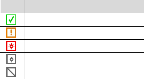
Table 7-1 Indicator Button
Button
Description
Indicates the monitoring item is complete.
Indicates the monitoring item is not complete.
Indicates the MIL is on.
Indicates the MIL is off.
Indicates the monitoring item is not supported.
15
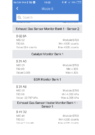
8 Mode 6
Mode 6 refers to the advanced test results for On-Board Diagnostic System
Monitors. Example monitors include Oxygen Sensors and Misfire Counters.
Mode 6 will tell you if the monitors are passing their tests and if the values
are within acceptable range. For each test, the result displays six
parameters, MID, TID, Module ID, Value, Min, and Max. MID (Monitor ID)
represents what is being tested. TID (Test ID) represents what specific test
is being running. Min is the minimal allowable test result that will not set a
DTC. Value is the actual result of the test. Max is the maximum allowable
test result that will not set a DTC.
Figure 8-1 Sample Mode 6 Screen
16
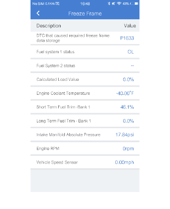
9 Freeze Frame
Freeze Frame provides a snapshot of vehicle data at the instant the Check
Engine Light (CEL) came on. Tap Freeze Frame. When the scan completes,
freeze frame data is available to be viewed.
Figure 9-1 Sample Freeze Frame Screen
17
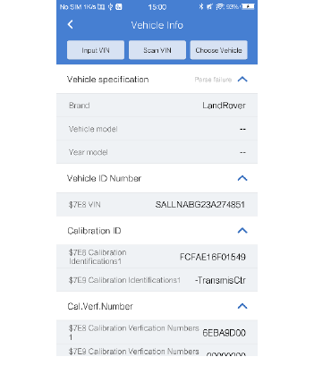
10 Vehicle Info
With the embedded AutoVIN technology, this option displays the vehicle
identification number (VIN), the calibration identification, the calibration
verification number (CVN), vehicle brand, model, year, and other
information of the test vehicle. Tap Vehicle Info to view the detailed vehicle
information that is based on vehicle VIN. If the vehicle VIN is not
automatically retrieved, tap the Input VIN to search or Scan VIN, or choose
the vehicle year and model step by step. All the three tabs are on the top of
the Vehicle Info screen.
Figure 10-1 Sample Vehicle Info Screen
18
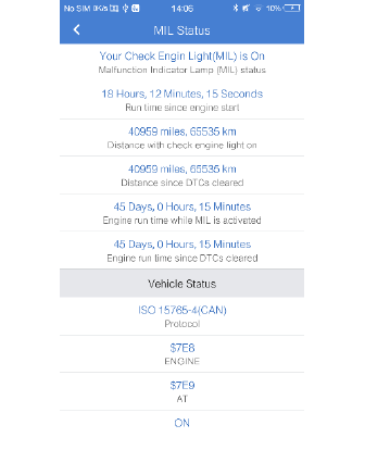
11 MIL Status
The Check Engine Light is also known as the Malfunction Indicator Lamp,
or MIL, and has more information to share besides being ON or OFF.
Tap MIL Status to display the MIL related information. The information
mainly include, MIL Status (ON or OFF), Run Time Since Engine Start,
Distance with MIL ON, and Distance Since Trouble Code Cleared. These
supported parameters vary by test vehicle.
Figure 11-1 Sample MIL Status Screen
19
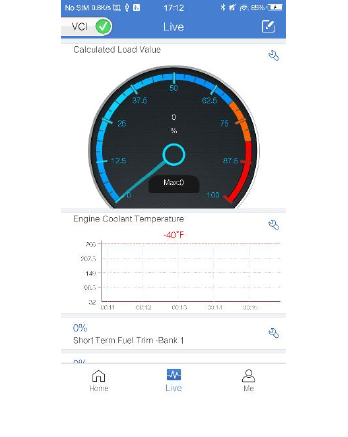
12 Live Data
Tap Live to view the list of available live data. Tap the button to view the
details of a specific live data. The details screen displays the descriptions
and you can change the display mode, unit, and custom range.
When this function is selected, the screen displays the data list for the
selected module. The items available for any control module vary by vehicle.
The parameters display in the order that they are transmitted by the ECM,
so expect variation between vehicles.
Figure 12-1 Sample Live Data Screen
20
13 Me
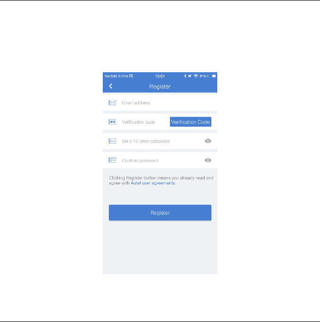
Register
1. Tap the Register button on the Settings screen.
2. Enter the email address, verification code and password accordingly in
the register screen. The verification code will be sent to your email
address after you tap the Verification code button.
3. Tap Register at the end to complete the registration.
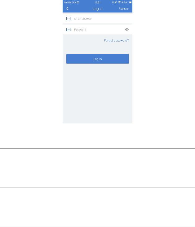
Log in
After registering the tool, log in with your registered email and password. If
you forget the password, you can tap the Forget password? button to
retrieve it.
Figure 13-1 Sample Register Screen
21
Online purchase
Online purchase will direct you to the Autel store, you can buy Autel
products online with this function.
Repair Reports
All the repair reports of each diagnostic session are saved here for review.
Please refer to Repair Reports on page 12 for details.
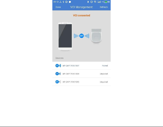
VCI Management
Manages the Bluetooth connection. To connect the device with the MaxiAP
AP100, turn on the device’s Bluetooth beforehand. Tap the Bluetooth name
of the MaxiAP AP100 to pair up with the device. When the device is
successfully paired up and communicating with the MaxiAP AP100, the LED
on the MaxiAP AP100 lights solid blue. Tap Done on the VCI Management
screen to return to Home Screen. Your MaxiAP AP100 is now ready to work.
Figure 13-2 Sample Log in Screen
22
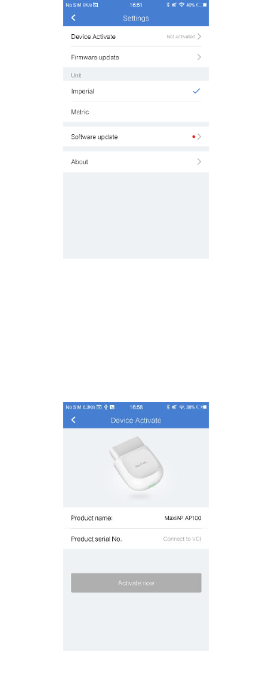
Settings
Select the Settings application to open a setup screen to adjust the default
setting and view information about the MaxiAP system. There are five
system settings.
Device Activate
Firmware update
Unit
Software update
About
Figure 13-3 Sample VCI Management Screen
23
Device Activate
The MaxiAP AP100 needs to be activated after first log in. Connect the
device with the MaxiAP AP100 connector and then tap Me>Settings>Device
Activate in the app to activate the device. Please refer to Powering Up on
page 6 for VCI connection details.
Figure 13-4 Sample Settings Screen
Figure 13-5 Sample Device Activate Screen
24
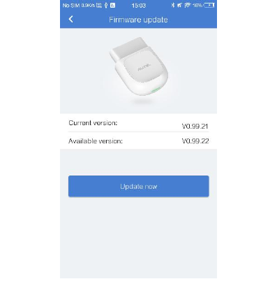
Firmware Update
This options allows you to update the firmware of the MaxiAP AP100
connector. Connect the device with the Internet and then tap
Me>Settings>Firmwadumre Update to update if new firmware version is
available.
Unit
This option allows you to adjust the measurement unit for the diagnostic
system. You can tap Imperial or Metric to switch between these two
measurement units.
Software Update
For Android devices, this option allows you to update the software when a
new version is available. For iOS devices, software update is notified in the
Updates section of the App Store.
Figure 13-6 Sample Firmware Update Screen
25
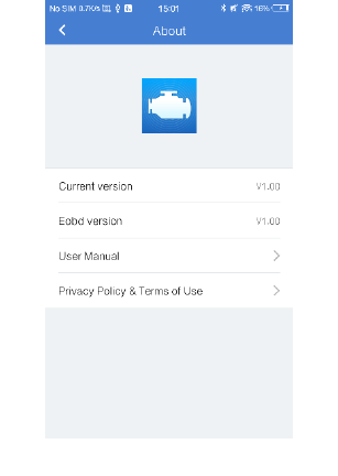
About
The About option displays the following information, current version of the
app, Eobd version, User Manual, Privacy Policy & Terms of Use. You can
tap User Manual and Privacy Policy & Terms of Use to view detailed
information.
Figure 13-7 Sample About Screen

26
14 Product Troubleshooting
This part describes problems that you may encounter while using the
MaxiAP AP100.
Vehicle Linking Error
A communication error occurs if the MaxiAP AP100 fails to communicate
with the vehicle’s control module when performing diagnostic procedures.
Please do the following check-ups:
Verify that the ignition is ON.
Check if the MaxiAP AP100 connector is securely connected to the
vehicle’s DLC.
Turn the ignition off and wait for about 10 seconds. Turn the ignition
back to on and continue the operation.
Verify the control module is not defective.

27
15 Compliance Information
FCC COMPLIANCE FCC ID: WQ82017MAXIAP
This device complies with Part 15 of the FCC Rules and with RSS-210 of
Industry Canada. Operation is subject to the following two conditions:
1 This device may not cause harmful interference.
2 This device must accept any interference received, including
interference that may cause undesired operation.
WARNING
Changes or modifications not expressly approved by the party responsible
for compliance could void the user’s authority to operate the equipment.
NOTE
This equipment has been tested and found to comply with the limits for a
Class B digital device, pursuant to Part 15 of the FCC Rules. These limits
are designed to provide reasonable protection against harmful interference
in a residential installation.
This equipment generates uses and can radiate radio frequency energy and,
if not installed and used in accordance with the instructions, may cause
harmful interference to radio communications. However, there is no
guarantee that interference will not occur in a particular installation. If this
equipment does cause harmful interference to radio or television reception,
which can be determined by turning the equipment off and on, the user is
encouraged to try to correct the interference by one or more of the following
measures: ⅰ. Reorient or relocate the receiving antenna. ⅱ. Increase the
separation between the equipment and receiver. ⅲ . Connect the
equipment into an outlet on a circuit different from that to which the receiver
is connected. ⅳ. Consult the dealer or an experienced radio/TV
technician for help.
FCC Radiation Exposure Statement:
28
This equipment complies with FCC radiation exposure limits set forth for an
uncontrolled environment. This equipment should be installed and operated
with minimum distance 20cm between the radiator & your body.
RoHS COMPLIANCE
This device is declared to be in compliance with the European RoHS
Directive 2011/65/EU.
CE COMPLIANCE
This product is declared to conform to the essential requirements of the
following Directives and carries the CE mark accordingly:
EMC Directive 2014/30/EU
R&TTE Directive 1999/5/EC
Low Voltage Directive 2014/35/EU

29
16 Warranty and Service
Limited One Year Warranty
Autel Intelligent Technology Corp., Ltd. (the Company) warrants to the
original retail purchaser of this Autel device that should this product or any
part thereof during normal usage and under normal conditions be proven
defective in material or workmanship that results in product failure within 1
year period from the date of purchase, such defect(s) will be repaired, or
replaced (with new or rebuilt parts) with Proof of Purchase, at the
Company’s option, without charge for parts or labor directly related to the
defect(s).
The Company shall not be liable for any incidental or consequential
damages arising from the use, misuse, or mounting of the device. Some
states do not allow limitation on how long an implied warranty lasts, so the
above limitations may not apply to you.
This warranty does not apply to:
1) Products subjected to abnormal use or conditions, accident,
mishandling, neglect, unauthorized alteration, misuse, improper
installation or repair or improper storage;
2) Products whose mechanical serial number or electronic serial number
has been removed, altered or defaced;
3) Damage from exposure to excessive temperatures or extreme
environmental conditions;
4) Damage resulting from connection to, or use of any accessory or other
product not approved or authorized by the Company;
5) Defects in appearance, cosmetic, decorative or structural items such
as framing and non-operative parts.
6) Products damaged from external causes such as fire, dirt, sand, battery
leakage, blown fuse, theft or improper usage of any electrical source.

30
IMPORTANT
All contents of the product may be deleted during the process of repair. You
should create a back-up copy of any contents of your product before
delivering the product for warranty service.
Service and Support
If you have any questions regarding the product, please contact one of our
offices in your region.
AUTEL NORTH AMERICA
Phone: 855-AUTEL-US (855-288-3587) Monday-Friday 9am-6pm
EST
Website: www.autel.com
Email: ussupport@autel.com
Address: 175 Central Avenue, Suite 200, Farmingdale, New York,
USA. 11735
AUTEL EUROPE
Phone: 0049 (0) 61032000522
Website: www.autel.eu
Email: sales.eu@autel.com, support.eu@autel.com
Address: Robert-Bosch-Strasse 25, 63225, Langen, Germany
AUTEL CHINA HQ
Phone: 0086-755-8614 7779
Website: www.autel.com
Email: support@autel.com
Address: 6th-10th floor, Building B1, Zhiyuan, Xueyuan Road, Xili,
Nanshan, Shenzhen, 518055, China.
AUTEL SOUTH AMERICA
Phone: (+507) 308-7566
Website: www.autel.com/es
Email: sales.latin@autel.com, latsupport@autel.com

31
Address: Office 103, Building 3845, International Business Park,
Veracruz, Panamá Pacífico, Panamá
AUTEL AUSTRALIA
Phone: 03 9480 2978 / +61 476293327
Website: www.autel.com.au
Email: sales@autel.com.au
Address: 155 Islington Street, Melbourne, Collingwood, VIC
For technical assistance in other markets, please contact your local
distributor.