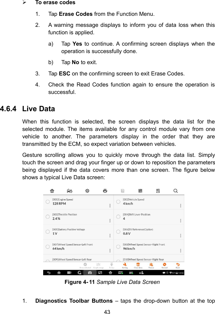
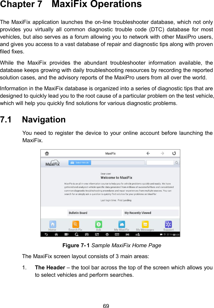
Autel Intelligent Tech MAXIPROMP908 AUTOMOTIVE DIAGNOSTIC & ANALYSIS SYSTEM User Manual
Autel Intelligent Tech. Corp., Ltd. AUTOMOTIVE DIAGNOSTIC & ANALYSIS SYSTEM
UserManual.wiki
>
Autel Intelligent Tech
>
MAXIPROMP908 User Manual
>
User Manual
Contents
1.
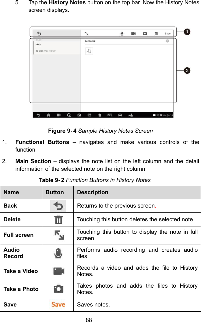
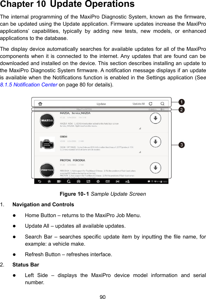
User Manual
2.
User_Manual
User Manual
User_Manual
Navigation menu
Upload a User Manual
Namespaces
Wiki Guide
HTML
PDF
Info
Views
User Manual
Discussion / Help
Navigation