Autel Intelligent Tech MXPRGXP201 MAXIPROGRAMMER 201 User Manual
Autel Intelligent Tech. Corp., Ltd. MAXIPROGRAMMER 201
User Manual
i
Trademarks
Autel®, MaxiSys®, MaxiDAS®, MaxiScan®, MaxiRecorder®, MaxiTPMS®, and
MaxiCheck® are trademarks of Autel Intelligent Technology Corp., Ltd.,
registered in China, the United States and other countries. All other marks are
trademarks or registered trademarks of their respective holders.
Copyright Information
No part of this manual may be reproduced, stored in a retrieval system or
transmitted, in any form or by any means, electronic, mechanical, photocopying,
recording, or otherwise, without the prior written permission of Autel.
Disclaimer of Warranties and Limitation of Liabilities
All information, specifications and illustrations in this manual are based on the
latest information available at the time of printing. Autel reserves the right to
make changes at any time without notice. While information of this manual has
been carefully checked for accuracy, no guarantee is given to the completeness
and correctness of the contents, including but not limited to the product
specifications, functions, and illustrations.
Autel will not be liable for any direct damages or for any special, incidental, or
indirect damages or for any economic consequential damages (including lost
profits).
IMPORTANT
Before operating or maintaining this unit, please read this manual carefully,
paying attention to the safety warnings and precautions.
For Services and Support:
http://pro.autel.com
www.autel.com
1-855-288-3587/1-855-AUTELUS (North America)
0086-755-86147779 (China)
Support@autel.com
For technical assistance in all other markets, please contact your local selling
agent.
ii
Contents
1 SAFETY PRECAUTIONS ................................................................ 1
2 INTRODUCTION ............................................................................ 2
SPECIFICATIONS ................................................................................ 2
ACCESSORIES INCLUDED .................................................................... 3
COMPONENTS AND PORTS .................................................................. 4
3 PRODUCT TROUBLESHOOTING .................................................13
4 UPDATE ........................................................................................14
SOFTWARE UPDATE ..........................................................................14
5 COMPLIANCE INFORMATION ......................................................16
6 WARRANTY AND SERVICE ..........................................................18
LIMITED ONE YEAR WARRANTY ..........................................................18
SERVICE INFORMATION ......................................................................19
1
1 Safety Precautions
The AUTEL MaxiProgrammer 201 (XP201 for short) has been
carefully designed to help automotive technicians maintaining and
servicing modern vehicles.
To avoid personal injury or damage to vehicles, please read this
manual first and observe the following safety precautions whenever
working on a vehicle.
Make sure:
The diagnosis or service is performed in a safe environment.
The vehicle is operated in a well-ventilated work area.
The vehicle parts and XP201 components are welded at a
constant temperature.
The vehicle and XP201 are powered off and grounded.
The XP201 is dry, clean, and free from oil, water, grease and dust.
Electrostatic interference is avoided during operation. If a failure
occurs due to electrostatic interference, please try to operate
again.
2
2 Introduction
The MaxiProgrammer 201 is specially designed to read Volkswagen
vehicle key chip data, clone and generate exclusive keys, read/write
on-board EEPROM data, and read/write Freescale 9S12 MCUs. By
working with diagnostic tool and PC that are both loaded with
programmer software, the MaxiProgrammer 201 can read/write key
chip data quickly and accurately.
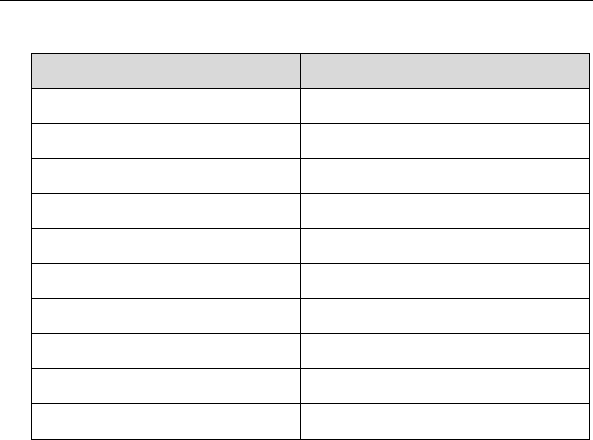
Specifications
Table 2-1 Specifications
Item
Description
Operating Temperature
-10℃ ~ 85℃ (14℉ ~ 185℉)
Storage Temperature
-20℃ ~ 85℃ (-4℉ ~ 185℉)
Port
Mini USB, VGA_DB15
Input Voltage
5 VDC
Operating Current
< 250 mA
Maximum Consumption
1 W
Device Dimensions (L*W*H)
130 mm * 68 mm * 28 mm
Package Dimensions (L*W*H)
201 mm * 167 mm * 75 mm
Net Weight
466 g
Gross Weight
11 kg (20 pcs)
3
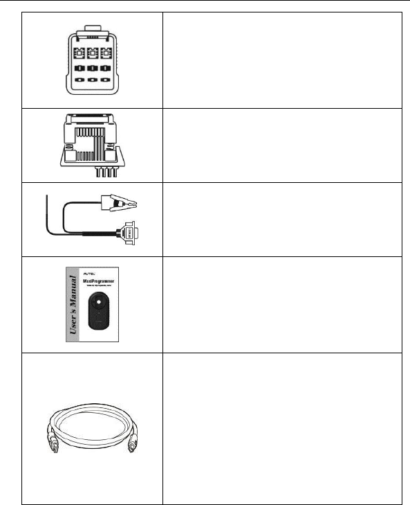
Accessories Included
APB001 – EEPROM Adaptor
APA002 – EEPROM Socket
APA001 – EEPROM Clamp Integrated
MC9S12 Cable
User’s Manual
APC001 – USB Cable (Standard USB –
Mini USB)
APC002 – USB Cable (Mini USB – Mini
USB) (Optional)
The two types of USB cables work with
different products, please choose the
corresponding USB cable for the product
you use.
4
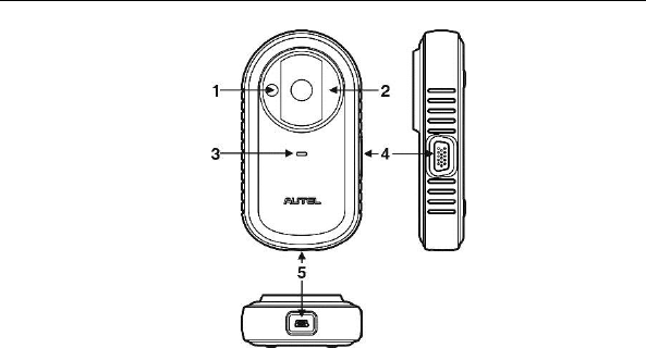
Components and Ports
Figure 2-1 MaxiProgrammer 201 Views
1. Vehicle Key Chip Slot – holds the vehicle key chip.
2. Vehicle Key Slot – holds the vehicle key.
3. Status LED Light – indicates the current operating status.
4. Connection Port – connects EEPROM Adaptor and EEPROM
Clamp Integrated MC9S12 Cable.
5. USB Port – provides data communication and power supply.
Vehicle Key Slot
Holds the Vehicle Key to read and write vehicle key information.
Vehicle Key Chip Slot
Holds the Vehicle Key Chip to read and write vehicle key chip
information.
Status LED Light
The status LED of the XP201 indicates the operating status of the

5
device. See Table 2-2 for detailed description.
Table 2-2 Status LED Light on the Front Panel
LED Light
Color/Status
Description
Power
Solid Green
Powered on and Default Status
Flashing Green
Communication Status
Solid Red
Error Status
Connection Port
There are two accessories that can be paired with the connection port:
EEPROM Clamp Integrated MC9S12 Cable and EEPROM Adaptor.
6
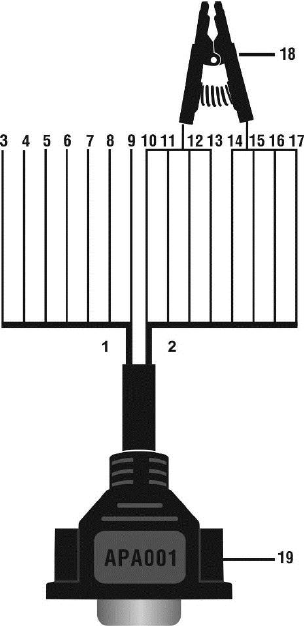
EEPROM Clamp Integrated MC9S12 Cable
Figure 2-2 EEPROM Clamp Integrated MC9S12 Cable
1. MC9S12 Cable

7
Table 2-3 Definitions of MC9S12 Cable
No.
Color
Definition
Pin correspond
to DB15
Note
3
Green
TXCLKS
1
4
Black
GND
2
Shielded line
5
White
TOSC
6
Shielded line
6
Blue
TSW
7
7
Brown
GND
8
8
Yellow
TRESET
11
9
Red
VDD
12
2. EEPROM Clamp Cable
Table 2-4 Definitions of EEPROM Clamp Cable
No.
Color
Definition
Pin correspond
to DB15
Note
10
White and
Red
P1
5
Pin 1 is red
11
White and
Purple
P2
15
12
White and
Blue
P3
10
13
Grey
P4
4
14
White and
Brown
P5
14
15
White and
Green
P6
9

8
16
White and
Orange
P7
3
17
White and
Black
P8
13
Pin 8 is
black
Here are the possible causes for EEPROM read/write failure and data
error when connecting the clamp to the test board for EEPROM
read/write:
A. EEPROM read/write operations are affected by the circuit of the
connected test board;
B. EEPROM read/write operations of the test board are affected by
the read/write operations of the clamp;
C. The signal is damaged by large resistance. A large resistance will
be generated when connecting the clamp to a fast communicating
EEPROM or using a long cable for connection.
Therefore, it is recommended to dismantle the chip on the EEPROM,
weld the EEPROM to the EEPROM adaptor or place in the EEPROM
socket, and then insert it in the EEPROM adaptor.
18. EEPROM Clamp
19. DB15 VGA Port
EEPROM Adaptor
The EEPROM adaptor is compatible with three 8-pin packaging
TSSOP, SOP, DIP connections, and each packaging reserves three
same ports, so the device will function properly when one port is
damaged. For SOP8 packaging, the EEPROM adaptor can also work
with the EEPROM socket. To do this, place the pins of the SOP8
EEPROM into the EEPROM accordingly and then insert them into the
EEPROM adaptor.
USB Port
The USB port is used for the data communication between the XP201

9
and the diagnostic device or the PC, and it is also the port for power
supply charge.
EEPROM Read/Write Supported Types
Chip Type
Name
Chip Type
Name
ATMEL
AT24C01
ST
M24C04
ATMEL
AT24C02
ST
M24C08
ATMEL
AT24C04
ST
M24C16
ATMEL
AT24C08
ST
M24C32
ATMEL
AT24C16
ST
M24C64
ATMEL
AT24C32
FAIRCHILD
NM24C16U
ATMEL
AT24C64
FAIRCHILD
NM24C16UT
ATMEL
AT24C128
FAIRCHILD
NM24C17U
ATMEL
AT24C256
FAIRCHILD
NM24C17UT
ATMEL
AT24C512
MICROCHIP
85C72
ATMEL
AT24C1024
MICROCHIP
85C82
ATMEL
AT24C128_1.8
MICROCHIP
85C92
ATMEL
AT24C256_1.8
NXP
PCF8582C
ATMEL
AT24C512_1.8
NXP
PCF8594C
ATMEL
AT24C01A
NXP
PCF8598C
ST
ST24x01/ST25x01
ATMEL
AT25010
ST
ST24x02/ST25x02
ATMEL
AT25020
ST
ST24x04/ST25x04
ATMEL
AT25040
ST
ST24x08/ST25x08
ATMEL
AT25080
ST
ST24x16/ST25x16
ATMEL
AT25160

10
Chip Type
Name
Chip Type
Name
ST
M24C01
ATMEL
AT25320
ST
M24C02
ATMEL
AT25640
ATMEL
AT25128
MICROCHIP
25xx080
ATMEL
AT25256
MICROCHIP
25xx160
ATMEL
AT25512
MICROCHIP
25xx320
ATMEL
AT25010_1.8
MICROCHIP
25xx640
ATMEL
AT25020_1.8
MICROCHIP
25xx040_TSSOP
ATMEL
AT25040_1.8
MICROCHIP
25xx320_TSSOP
ATMEL
AT25080_1.8
MICROCHIP
25xx640_TSSOP
ATMEL
AT25160_1.8
CATALYST
CAT25C01
ATMEL
AT25320_1.8
CATALYST
CAT25C02
ATMEL
AT25640_1.8
CATALYST
CAT25C04
ATMEL
AT25128_1.8
CATALYST
CAT25C08
ATMEL
AT25256_1.8
CATALYST
CAT25C16
ST
M95010
CATALYST
CAT25C32
ST
M95020
CATALYST
CAT25C64
ST
M95040
CATALYST
CAT25C128
ST
M95080
CATALYST
CAT25C256
ST
M95160
ST
M35080
ST
M95320
XICOR
X5043
ST
M95640
XICOR
X5045
ST
M95128
XICOR
X25043
ST
M95256
XICOR
X25045

11
Chip Type
Name
Chip Type
Name
ST
M95512
MICROCHIP
93C06
MICROCHIP
25xx040
NATIONAL
NM93C13
NATIONAL
NM93C14
NATIONAL
NM93CS06
NATIONAL
NM93C14TM8
NATIONAL
NM93CS46
MICROCHIP
93C46X
NATIONAL
NM93CS56
MICROCHIP
93C46A
NATIONAL
NM93CS66
MICROCHIP
93C46
FAIRCHILD
FM93CS46T
MICROCHIP
93C46AX
ST
M93C46
MICROCHIP
93C46BX_93C46CX
ST
M93C56
MICROCHIP
93C56A
ST
M93C66
MICROCHIP
93C56
ST
M93C76
MICROCHIP
93C66A
ST
M93C86
MICROCHIP
93C66
ST
M93S46
MICROCHIP
93C76A
ST
M93S56
MICROCHIP
93C76
ST
M93S66
MICROCHIP
93C86A
ATMEL
AT59C11
MICROCHIP
93C86
ATMEL
AT59C22
ATMEL
AT93C46A
ATMEL
AT59C13
ATMEL
AT93C46
OKI
MSM16911
ATMEL
AT93C46R
TMC
TMC93LC46
ATMEL
AT93C56
TMC
TMC93LC56
ATMEL
AT93C57
TMC
TMC93LC57
ATMEL
AT93C66
TMC
TMC93LC66

12
Chip Type
Name
Chip Type
Name
ATMEL
AT93C76
TMC
TMC93LC86
ATMEL
AT93C86
SONY
CXK1011
SONY
CXK1012
Seiko
S_24S45
SONY
CXK1013
TOSHIBA
TC89101
Seiko
S_24H30
TOSHIBA
TC89102
Seiko
S_24H30_SOP8
TOSHIBA
TC89121
Seiko
S_24H45
TOSHIBA
TC89122
Seiko
S_24H45_SOP8
Xicor
X24C44
Seiko
S_24S30
9S12 Read/Write Supported Types
Chip Type
Name
FREESCALE
MC9S12DG128
13
3 Product Troubleshooting
This part describes problems that you may encounter while using the
XP201.
Vehicle Linking Error
A communication error occurs if the XP201 fails to communicate with
the diagnostic tools. Please do the following check-ups:
Verify that the diagnostic tool authorization is approved.
Verify that the server works properly.
Verify that the power LED light of the XP201 illuminates solid
green.
PC Communication Error
A communication error occurs if the XP201 fails to communicate with
PC. Please do the following check-ups:
Verify that the power LED light of the XP201 illuminates solid
green.
Check if there is any firewall software interfering with the
connection port or if a wrong USB port is being used.
Check if the green status light for USB communication is blinking.
If these issues have been addressed, verified, and you are still having
trouble, please contact technical supports for assistance.

14
4 Update
Software Update
This part describes two ways to update the driver and the software of
the XP201.
Update via MaxiSys Display Tablet
This function allows you to update the XP201 software via MaxiSys
Display Tablet.
1. Connect the XP201 to MaxiSys Display Tablet via USB cable.
2. Verify the power LED light on the front panel illuminates solid
green.
3. MaxiSys Display Tablet will automatically check the version
information of the XP201.
4. Click the Update button on MaxiSys Display Tablet to update the
software of the XP201 if there is any update available.
Update via PC
This function allows you to update the XP201 software via PC. Make
sure the PC is connected to the Internet before using this function.
1. Connect the XP201 to a PC via USB cable.
2. Verify the power LED light on the front panel illuminates solid
green.
3. Find and click Update Details from Windows Update Information.
15
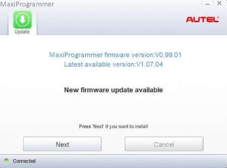
Figure 4-1 Sample Firmware Update Screen
4. The update agent will automatically check for available update
online.
5. Press Next to install the newest firmware.
6. Press Cancel to exit.
16
5 Compliance Information
FCC COMPLIANCE FCC ID: WQ8MXPRGXP201
This device complies with Part 15 of the FCC rules and Industry
Canada’s licence-exempt RSSs. Operation is subject to the following
two conditions:
1. This device may not cause harmful interference.
2. This device must accept any interference received, including
interference that may cause undesired operation.
Cet appareil est conforme aux CNR exempts de licence d'Industrie
Canada. Son fonctionnement est soumis aux deux conditions
suivantes:
1. Ce dispositif ne peut causer des interferences; et
2. Ce dispositif doit accepter toute interférence, y compris les
interférences qui peuvent causer un mauvais fonctionnement de
l'appareil.
WARNING
Changes or modifications not expressly approved by the party
responsible for compliance could void the user's authority to operate
the equipment.
NOTE
This equipment has been tested and found to comply with the limits for
a Class B digital device, pursuant to Part 15 of the FCC Rules. These
limits are designed to provide reasonable protection against harmful
interference in a residential installation.
This equipment has been tested and found to comply with the limits for
a Class B digital device, pursuant to Part 15 of the FCC Rules. These
limits are designed to provide reasonable protection against harmful
interference in a residential installation. This equipment generates
uses and can radiate radio frequency energy and, if not installed and
17
used in accordance with the instructions, may cause harmful
interference to radio communications. However, there is no guarantee
that interference will not occur in a particular installation. If this
equipment does cause harmful interference to radio or television
reception, which can be determined by turning the equipment off and
on, the user is encouraged to try to correct the interference by one or
more of the following measures:
-- Reorient or relocate the receiving antenna.
-- Increase the separation between the equipment and receiver.
-- Connect the equipment into an outlet on a circuit different from that
to which the receiver is connected.
-- Consult the dealer or an experienced radio/TV technician for help.
Changes or modifications not expressly approved by the party
responsible for compliance could void the user's authority to operate
the equipment.
RF WARNING STATEMENT
The device has been evaluated to meet general RF exposure
requirement. The device can be used in portable exposure condition
without restriction.
The term “IC” before the radio certification number only signifies that
IC technical specifications were met.
RoHS COMPLIANCE
This device is declared to be in compliance with the European RoHS
Directive 2011/65/EU.
CE COMPLIANCE
This product is declared to conform to the essential requirements of
the following Directives and carries the CE mark accordingly:
EMC Directive 2014/30/EU
R&TTE Directive 1999/5/EC
Low Voltage Directive 2014/35/EU

18
6 Warranty and Service
Limited One Year Warranty
Autel Intelligent Technology Corp., Ltd. (the Company) warrants the
original retail purchaser of this MaxiProgrammer 201 that should this
product or any part thereof during normal usage and under normal
conditions be proven defective in material or workmanship and results
in product failure within 1 year period from the date of delivery, such
defect(s) will be repaired, or replaced (with new or rebuilt parts) with
Proof of Purchase, at the Company’s option, without charge for parts
or labor directly related to the defect(s).
The Company shall not be liable for any incidental or consequential
damages arising from the use, misuse, or mounting of the device.
Some states do not allow limitation on how long an implied warranty
lasts, so the above limitations may not apply to you.
This warranty does not apply to:
1) Products subjected to abnormal use or conditions, accident,
mishandling, neglect, unauthorized alteration, misuse, improper
installation or repair or improper storage;
2) Products whose mechanical serial number or electronic serial
number has been removed, altered or defaced;
3) Damage from exposure to excessive temperatures or extreme
environmental conditions;
4) Damage resulting from connection to, or use of any accessory or
other product not approved or authorized by the Company;
5) Defects in appearance, cosmetic, decorative or structural items
such as framing and non-operative parts.
6) Products damaged from external causes such as fire, dirt, sand,
battery leakage, blown fuse, theft or improper usage of any
electrical source.

19
Service Information
If you have any questions, please contact your local distributor or visit
our website at www.autel.com.
If it becomes necessary to return the tool for repair, please download
and fill the Technical Support Form from www.auteltech.com, or
contact your local distributor for more information.
Other Services
Accessories can be purchased from Autel authorized suppliers and
your local distributors.