Avaya Canada BTR2807M LMDS BTS Transceiver User Manual 0000007 08 0283
Avaya Canada Corporation LMDS BTS Transceiver 0000007 08 0283
UserManual.wiki
>
Avaya Canada
>
BTR2807M User Manual
>
Installation Manual
Contents
1.
BTR manual
2.
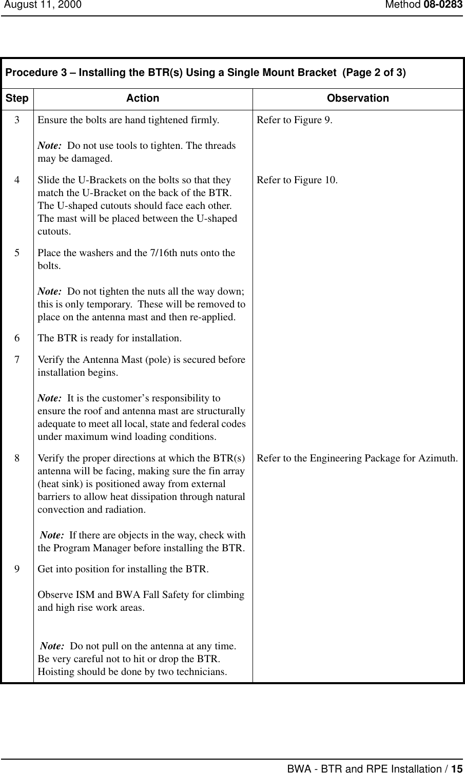
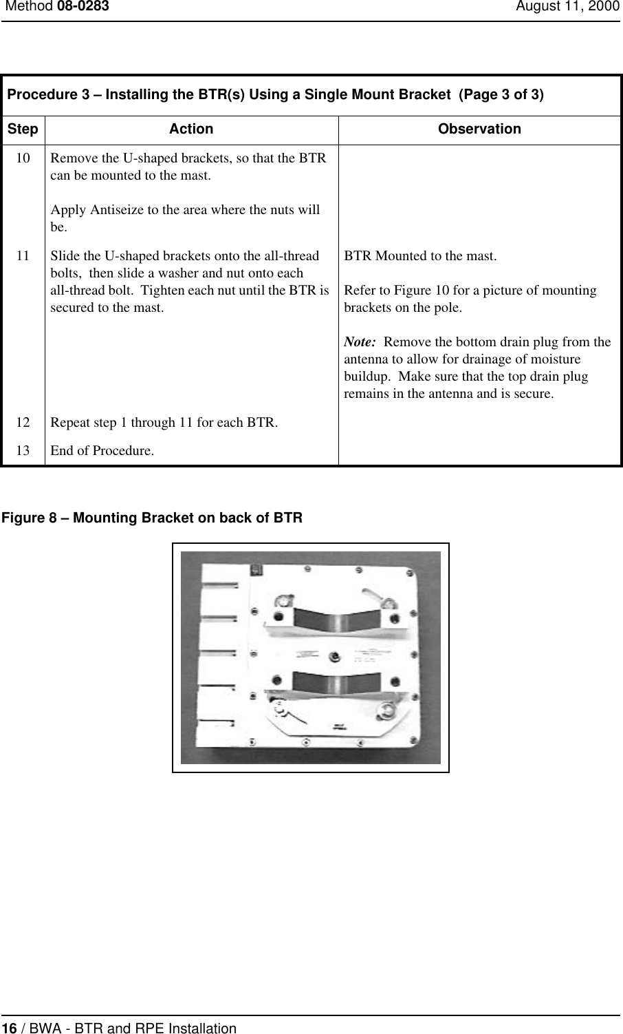
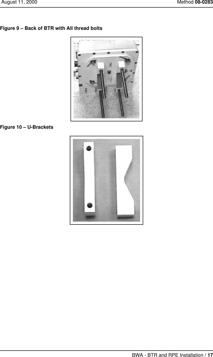
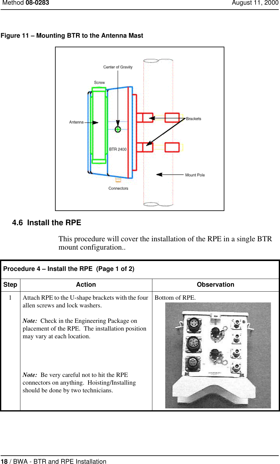
Installation Manual
Installation Manual
Navigation menu
Upload a User Manual
Namespaces
Wiki Guide
HTML
PDF
Info
Views
User Manual
Discussion / Help
Navigation