Avaya Canada BTR2807M LMDS BTS Transceiver User Manual 0000007 08 0283
Avaya Canada Corporation LMDS BTS Transceiver 0000007 08 0283
Contents
- 1. BTR manual
- 2. Installation Manual
Installation Manual

PROPRIETARY INFORMATION: The information contained in this document
is the property of Nortel Networks. Except as specifically authorized in writing,
the holder of this document shall keep all information contained herein
confidential and shall protect same in whole or in part from disclosure and
dissemination to third parties.
BWA - BTR and RPE Installation
Installation Method - 08-0283
August 11, 2000
Issue Number: 02.0
Pkgid: 0000007
Nortel Networks 2000
All Rights Reserved

0 / BWA - BTR and RPE Installation
Method 08-0283 August 11, 2000

BWA - BTR and RPE Installation / 1
August 11, 2000 Method 08-0283
Table of Contents
1.0 General Information . . . . . . . . . . . . . . . . . . . . . . . . . . . . . . . . . . . . . . . . . . . . . . . . . . . . . . . 3
1.1 Description . . . . . . . . . . . . . . . . . . . . . . . . . . . . . . . . . . . . . . . . . . . . . . . . . . . . . . . . . . . . 3
1.2 Sequence . . . . . . . . . . . . . . . . . . . . . . . . . . . . . . . . . . . . . . . . . . . . . . . . . . . . . . . . . . . . . 3
1.3 Reason for Reissue . . . . . . . . . . . . . . . . . . . . . . . . . . . . . . . . . . . . . . . . . . . . . . . . . . . . . . 3
2.0 Material Requirements . . . . . . . . . . . . . . . . . . . . . . . . . . . . . . . . . . . . . . . . . . . . . . . . . . . . . 3
2.1 Required Documents . . . . . . . . . . . . . . . . . . . . . . . . . . . . . . . . . . . . . . . . . . . . . . . . . . . . 3
2.2 Tools . . . . . . . . . . . . . . . . . . . . . . . . . . . . . . . . . . . . . . . . . . . . . . . . . . . . . . . . . . . . . . . . . 4
2.3 Supplies . . . . . . . . . . . . . . . . . . . . . . . . . . . . . . . . . . . . . . . . . . . . . . . . . . . . . . . . . . . . . . 4
2.4 Customer Supplied Equipment . . . . . . . . . . . . . . . . . . . . . . . . . . . . . . . . . . . . . . . . . . . . . 4
2.5 Emergency Contacts . . . . . . . . . . . . . . . . . . . . . . . . . . . . . . . . . . . . . . . . . . . . . . . . . . . . . 4
3.0 Precautions and Preparations . . . . . . . . . . . . . . . . . . . . . . . . . . . . . . . . . . . . . . . . . . . . . . . 5
3.1 Precautions . . . . . . . . . . . . . . . . . . . . . . . . . . . . . . . . . . . . . . . . . . . . . . . . . . . . . . . . . . . . 5
3.2 Preparations . . . . . . . . . . . . . . . . . . . . . . . . . . . . . . . . . . . . . . . . . . . . . . . . . . . . . . . . . . . 5
4.0 Procedure . . . . . . . . . . . . . . . . . . . . . . . . . . . . . . . . . . . . . . . . . . . . . . . . . . . . . . . . . . . . . . . . 6
4.1 Overview . . . . . . . . . . . . . . . . . . . . . . . . . . . . . . . . . . . . . . . . . . . . . . . . . . . . . . . . . . . . . . 6
4.2 Unpacking the BTR . . . . . . . . . . . . . . . . . . . . . . . . . . . . . . . . . . . . . . . . . . . . . . . . . . . . . . 7
4.3 Preparing BTR for Installation . . . . . . . . . . . . . . . . . . . . . . . . . . . . . . . . . . . . . . . . . . . . . . 7
Procedure 1 – Preparing BTR for Installation (Page 1 of 2) . . . . . . . . . . . . . . . . . . . . . . . 7
4.4 Installation of a BTR using a Single Mount Fine Adjustment Bracket . . . . . . . . . . . . . . . 11
Procedure 2 – Installation of a BTR using a Fine Adjustment Bracket (Page 1 of 4) . . 11
4.5 Installing the BTR(s) Using a Single Mount Bracket . . . . . . . . . . . . . . . . . . . . . . . . . . . . 14
Procedure 3 – Installing the BTR(s) Using a Single Mount Bracket (Page 1 of 3) . . . . 14
4.6 Install the RPE . . . . . . . . . . . . . . . . . . . . . . . . . . . . . . . . . . . . . . . . . . . . . . . . . . . . . . . . 18
Procedure 4 – Install the RPE (Page 1 of 2) . . . . . . . . . . . . . . . . . . . . . . . . . . . . . . . . . 18
4.7 Installing the BTR(s) Using A Dual Mount Bracket. . . . . . . . . . . . . . . . . . . . . . . . . . . . . 19
Procedure 5 – Installing the BTR(s) Using A Dual Mount Bracket (Page 1 of 3) . . . . . . 19
4.8 Alignment of BTR(s) . . . . . . . . . . . . . . . . . . . . . . . . . . . . . . . . . . . . . . . . . . . . . . . . . . . . 22
Procedure 6 – Alignment of BTR(s) (Page 1 of 4) . . . . . . . . . . . . . . . . . . . . . . . . . . . . . 22
5.0 References . . . . . . . . . . . . . . . . . . . . . . . . . . . . . . . . . . . . . . . . . . . . . . . . . . . . . . . . . . . . . . 28
6.0 Appendices . . . . . . . . . . . . . . . . . . . . . . . . . . . . . . . . . . . . . . . . . . . . . . . . . . . . . . . . . . . . . 28
Appendix A - Acronyms . . . . . . . . . . . . . . . . . . . . . . . . . . . . . . . . . . . . . . . . . . . . . . . . . . . . . 29
Last Page. . . . . . . . . . . . . . . . . . . . . . . . . . . . . . . . . . . . . . . . . . . . . . . . . . . . . . . . . . . . . . . . 29

2 / BWA - BTR and RPE Installation
Method 08-0283 August 11, 2000
Illustrations
Figure 1 – Tools . . . . . . . . . . . . . . . . . . . . . . . . . . . . . . . . . . . . . . . . . . . . . . . . . . . . . . . . . . . .4
Figure 2 – BTR Antenna Polarity . . . . . . . . . . . . . . . . . . . . . . . . . . . . . . . . . . . . . . . . . . . . . .9
Figure 3 – Tape Covering Flange . . . . . . . . . . . . . . . . . . . . . . . . . . . . . . . . . . . . . . . . . . . . .9
Figure 4 – Flange of BTR . . . . . . . . . . . . . . . . . . . . . . . . . . . . . . . . . . . . . . . . . . . . . . . . . . .10
Figure 5 – Antenna Bottom . . . . . . . . . . . . . . . . . . . . . . . . . . . . . . . . . . . . . . . . . . . . . . . . . .10
Figure 6 – BTR with Antenna in postion . . . . . . . . . . . . . . . . . . . . . . . . . . . . . . . . . . . . . . . . .10
Figure 7 – RF Reflectors mounted to Antenna . . . . . . . . . . . . . . . . . . . . . . . . . . . . . . . . . . . .11
Figure 8 – Mounting Bracket on back of BTR . . . . . . . . . . . . . . . . . . . . . . . . . . . . . . . . . . . .16
Figure 9 – Back of BTR with All thread bolts . . . . . . . . . . . . . . . . . . . . . . . . . . . . . . . . . . . . .17
Figure 10 – U-Brackets . . . . . . . . . . . . . . . . . . . . . . . . . . . . . . . . . . . . . . . . . . . . . . . . . . . . .17
Figure 11 – Mounting BTR to the Antenna Mast . . . . . . . . . . . . . . . . . . . . . . . . . . . . . . . . . .18
Figure 12 – Alignment Tool Parts . . . . . . . . . . . . . . . . . . . . . . . . . . . . . . . . . . . . . . . . . . . . . .26
Figure 13 – BTR Alignment Tool . . . . . . . . . . . . . . . . . . . . . . . . . . . . . . . . . . . . . . . . . . . . . .26
Figure 14 – Azimuth Plate . . . . . . . . . . . . . . . . . . . . . . . . . . . . . . . . . . . . . . . . . . . . . . . . . . .27
Figure 15 – Alignment Tool mounted to the BTR . . . . . . . . . . . . . . . . . . . . . . . . . . . . . . . . . .27

BWA - BTR and RPE Installation / 3
August 11, 2000 Method 08-0283
1.0 General Information
1.1 Description
Purpose: This method describes the handling and securing of the
Outdoor Microwave Units to include a pair of Base Station
Transceivers(BTR), Radio Power Extractor (RPE), antenna, and a dual
or single mounting bracket. The BTR is a combined broadband
transmitter and receiver deployed in Reunion’s point-to-multipoint
system.
Equipment: A pair of BTR’s with antennas, RPE, fine adjustment
single mount bracket, single mount braket, and dual mount bracket.
The BTR is approved for installation in an environment with an
expected temperature range of -40 Degrees to +50 Degrees Celsius.
The RPE is located close to the BTR. It provides 1:1 switching facility
between the primary and the redundant BTR.
Application: This method is intended for initial installations and NNE
Sector Extensions.
Service Impact: None
1.2 Sequence
This method is to be performed after Method 08-0289, "NNE
Installation."
1.3 Reason for Reissue
Document was revitalized and edited for content (July 2000).
This is the initial release of this method.
2.0 Material Requirements
2.1 Required Documents
Installation Safety Manual (ISM) at URL - aralia/usa/safety/safety.html.
Engineering Package
JSIP

4 / BWA - BTR and RPE Installation
Method 08-0283 August 11, 2000
2.2 Tools
The tools listed in Figure 1 are required to perform this method.
2.3 Supplies
50’ rope (optional)
Antiseize
2.4 Customer Supplied Equipment
Secured Antenna Mast
Mast Ground
Coax Cables for each sector run from NNE cabinet to roof.
One 4 pair 8 pin cable for each sector run from NNE cabinet to roof.
2.5 Emergency Contacts
For U.S. Wireless Market:
•Nortel Emergency Technical Assistance Service (ETAS)
972-BWA-ETAS (972-292-3827)
•Nortel Networks Technical Assistance Center (TAC)
972-292-3827, option #3
Figure 1 – Tools
Tools Description
K003041 Field Technicians Tool Kit
K003068 STL Tool Kit

BWA - BTR and RPE Installation / 5
August 11, 2000 Method 08-0283
3.0 Precautions and Preparations
3.1 Precautions
Observe the general safety precautions against personal injury and
equipment damage outlined in the ISM at all times.
Note: Read this method completely prior to attempting to handle or
install the BTR Transceiver or its mounting pedestal.
Any on-site problems, non-compliances with work orders or potential
hazards should be reported immediately to the Program Manager.
When working on high buildings extra care must be taken to ensure that
no debris, tools, or equipment are allowed to blow off or fall from the
working area.
Locate the main power shut-off switch controlling the equipment. This
is important in the event of an accident, so power can be quickly cut.
3.2 Preparations
Prior to starting the operations presented in this method, arrange all
materials, tools, and test equipment at the work location so as to
minimize fatigue and inconvenience.
On arrival at site, carefully move the equipment and materials to the
installation area. Unpack the equipment in a dry area and ensure that all
the required materials are present in accordance with the Packing List
and that there are no signs of damage. Report any damage or shortage
to the next level of support.
SHOCK:
Disconnect all power when working on power supplies.
CAUTION/WARNING:
Be aware of electrostatic discharge devices (ESD)
requirements when handling BWA equipment.

6 / BWA - BTR and RPE Installation
Method 08-0283 August 11, 2000
4.0 Procedure
4.1 Overview
This method covers the procedures required for the handling and
securing of the Outdoor Microwave Units. In this procedure I&C will
be preparing the BTR(s) for installation. Then the BTR(s) will be
mounted with the Fine Adjustment bracket, Single Mount bracket, or
the Dual Mount bracket. In addition, the RPE will be installed. Finally,
the BTR(s) will be aligned using the BTR Alignment Tool.
Note: There are several different options on mounting the BTR(s) and
RPE. Verify in the Engineering Package which option will be used. If
there is a special request made on mounting the BTR(s) and RPE, check
with the Program Manager before installation. There are spacing
measurements given in the Engineering Package for mounting the
BTR(s). They must be followed!
CAUTION/WARNING:
Do not stand in front of a transmitting radio or antenna.
CAUTION/WARNING:
The BTR will be installed on the roof or side of a building. It is
important to observe where the installation will take place. On
the way to that location, pay close attention to any hazard
spots (Things Hanging Down, Slippery or Wet Areas...etc.).
Once at the installation location, observe the surroundings for
any hazards.

BWA - BTR and RPE Installation / 7
August 11, 2000 Method 08-0283
4.2 Unpacking the BTR
1Check each package for any sign of physical damage. If damage is
visible, immediately report to the next level of support.
2Check all contents against the Bill of Materials (BOM), order forms and
packing slips to ensure that all components are received. Make notes of
any missing parts or equipment.
3Know exactly where to place the equipment, before removing it from
the package.
4Carefully remove the equipment from the package and closely inspect
all components for obvious signs of damage. If damage is visible,
immediately report to the Program Manager.
5Inventory and baseline all serial numbers, PEC Codes, and location of
where these components will be placed.
4.3 Preparing BTR for Installation
The following procedure covers the preparation required before
installing the BTR. The antenna (feedhorn) will be mounted to the BTR
before the BTR can be installed.
Procedure 1 – Preparing BTR for Installation (Page 1 of 2)
Step Action Observation
1There are two BTR(s) per sector. One is the
Primary and the other is the Redundant BTR.
Mount the antennas to the BTR(s) before
installing the BTR(s) to the mounting brackets.
The next steps will cover the procedure of
installing the antenna.
Note: Because it is important that installing the
antennas is done right, it should be done in a
controlled environment on stable ground, not
hanging from the mast.

8 / BWA - BTR and RPE Installation
Method 08-0283 August 11, 2000
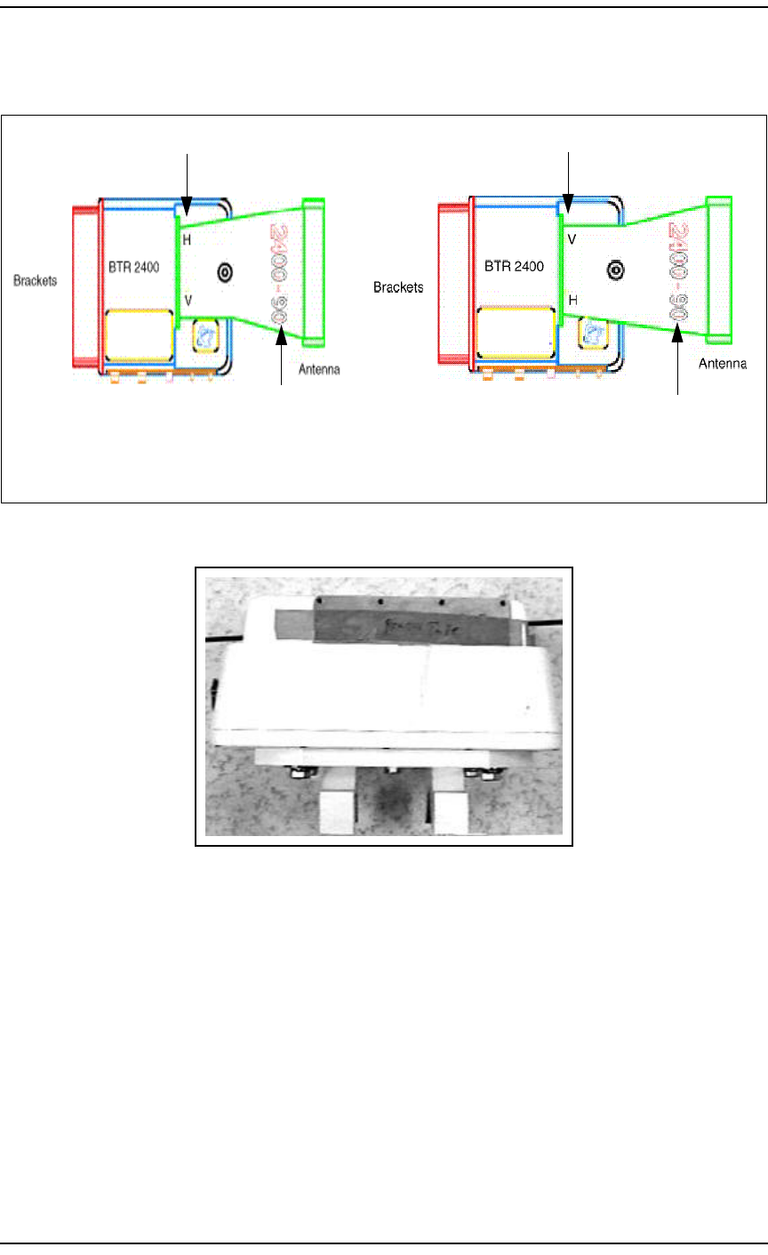
2Both BTR(s) must have the same antenna angle.
Verify the antenna angle to the Engineering
Package. It is engraved on the side of the
antenna.
Both the Primary and the Redundant BTR(s)
MUST use the same TX polarity. Verify in the
Engineering Package the TX polarity for each
sector.
Note: If the angle does not match the
Engineering package, do not proceed with this
procedure. Contact the Program Manager.
Note: Polarity is stamped onto the antenna.
Refer to Figure 2.
3Place the BTR on solid ground to install the
antenna. Refer to Figure 3 and Figure 4.
Note: The BTR will have tape covering the
waveguide holes so that debris can’t get inside
the radio. This tape will need to be removed
before installing the antenna.
4Carefully place the antenna’s flanged surface
against the BTR waveguide mounting surface.
Be sure to observe antenna polarity, placing the
TX polarity to the top of the BTR.
Apply the supplied silicone Gel to O Ring Seal.
Refer to Figure 5.
Refer to Figure 6.
The antenna is in position to be secured to the
BTR.
Note: Do not pull on the O Ring Seal. It
MUST stay attached to the antenna.
5There will be eight 9/64 allen head screws and
eight lock washers used to attach the antenna to
the BTR.
6Insert each screw and loosely tighten until all
screws are placed into the BTR . Then tighten
each screw using the torque screwdriver (18-
20 inch lbs.).
The antenna is now secured to the BTR
housing.
7Once the antenna is mounted, verify that there
are no gaps between the antenna and the BTR. Note: Verify Tx Polarity with the Engineering
Package.
8Using the 1/2 inch bolt, lock washer and washer,
place the bolt into the mounting hole on the side
of the antenna and tighten just so it is snug. Do
not over tighten.
Refer to Figure 6.
Now the antenna should fit flush to the housing
and be secured to the BTR.
9Attach the RF reflectors to the cylinder at the end
of the antenna using two screws. Refer to Figure 7.
10 End of Procedure.
Procedure 1 – Preparing BTR for Installation (Page 2 of 2)
Step Action Observation
BWA - BTR and RPE Installation / 9
August 11, 2000 Method 08-0283
Figure 2 – BTR Antenna Polarity
Figure 3 – Tape Covering Flange
Horizontal Polarity Vertical Polarity
Note H is on Top Note V is on Top
**To change polarity you must flip antenna 180 degrees**
Degree of Angle
Degree of Angle
10 / BWA - BTR and RPE Installation
Method 08-0283 August 11, 2000
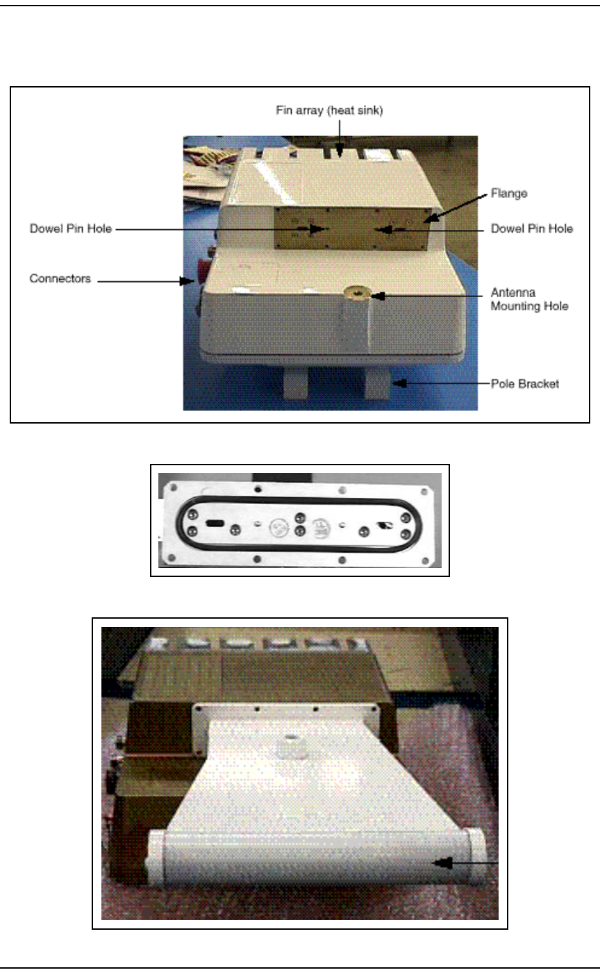
Figure 4 – Flange of BTR
Figure 5 – Antenna Bottom
Figure 6 – BTR with Antenna in postion
Transceiver
Antenna
BWA - BTR and RPE Installation / 11
August 11, 2000 Method 08-0283
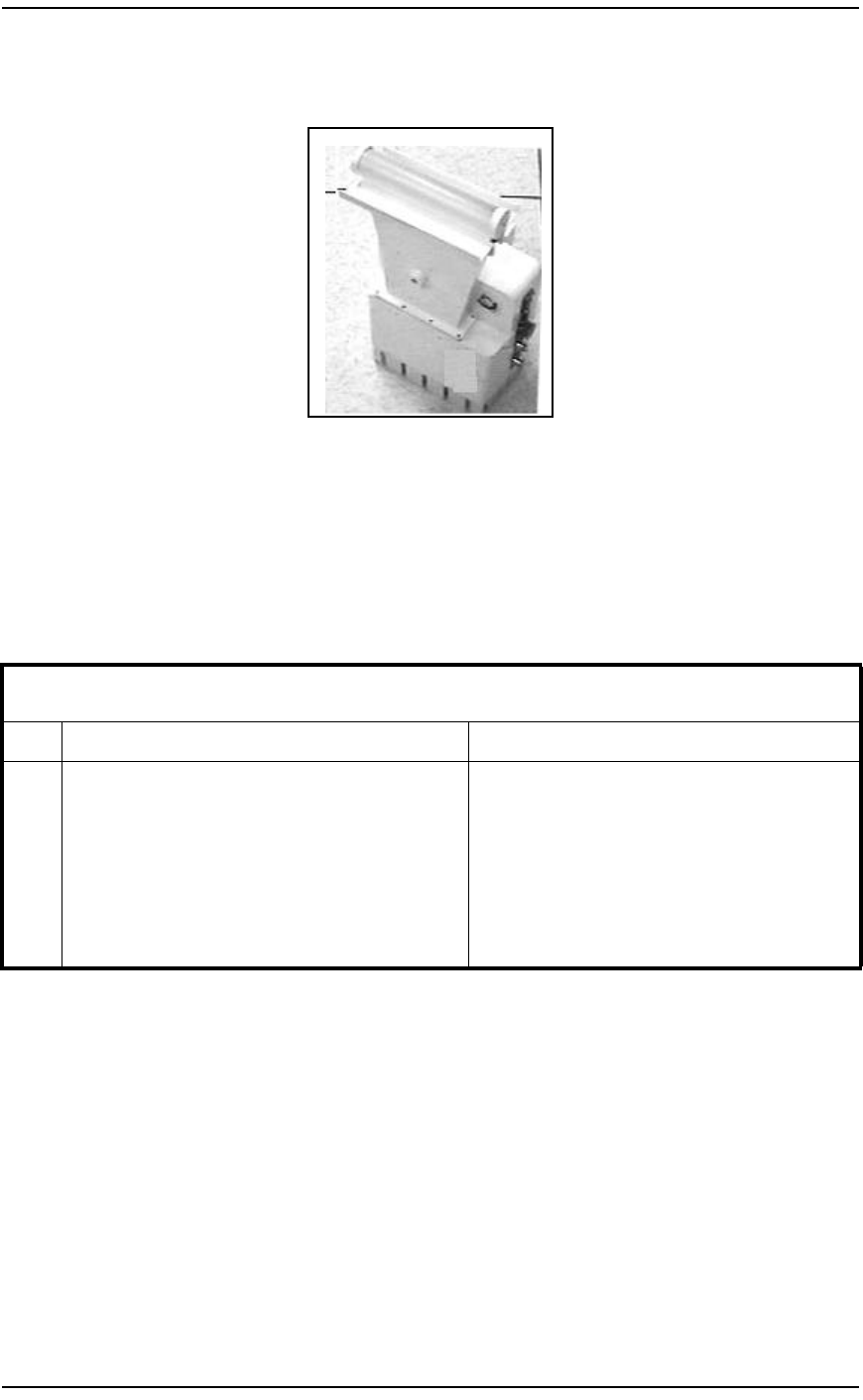
Figure 7 – RF Reflectors mounted to Antenna
4.4 Installation of a BTR using a Single Mount Fine Adjustment Bracket
The following procedure covers the assembly of the Single Mount Fine
Adjustment Bracket.
This procedure will require two technicians to perform.
Procedure 2 – Installation of a BTR using a Fine Adjustment Bracket (Page 1 of 4)
Step Action Observation
1Install the Azimuth adjustment plate to the mast
opposite direction of the sector aligned to. Using
the U-bolt, split lock washer, flat washer and
bronze nut, fully tighten the azimuth adjustment
plate securely to the pole.
PARTS: U-bolt bracket, two 3/8 x 16 bronze
nuts, flat washers, split lock washers.

12 / BWA - BTR and RPE Installation
Method 08-0283 August 11, 2000
2Install the Elevation adjustment plate to the mast
so that it sits on the Azimuth adjustment plate
assembly. Tighten the two pole clamp bars using
the four 6.0" hex bolts, split lock washers, flat
washers and hex nuts. The elevation adjustment
plate will fit snug to the pole.
Note: The azimuth adjust rod is pre assembled
when shipped from the factory. Remove the hex
nut, split lock washer and flat washer. Slip the
rod into the slot of the azimuth adjustment plate.
Replace the hex nut, split lock washer and flat
washer.
PARTS: Four 3/8 - 16 x 6.0" hex nut, 3/8 split
lock washer, 3/8 flat washers.
3Install elevation adjustment plate to the BTR
antenna bracket.
Attach the mounting plate to the elevation
adjustment plate using five pan head screws and
stainless steel split lock washers. Tighten the
mounting plate to the elevation adjustment plate.
PARTS: Five 1/4-20 x 3/8 pan head screws and
stainless steel split lock washers.
4Attach mounting plate to the Reunion Radio
housing using four pan head screws and stainless
steel split lock washers. Tighten fully.
PARTS: Four 1/4-28 x 3/4 pan head screws and
stainless steel split lock washers.
Procedure 2 – Installation of a BTR using a Fine Adjustment Bracket (Page 2 of 4)
Step Action Observation

BWA - BTR and RPE Installation / 13
August 11, 2000 Method 08-0283
5Insert elevation adjustment assembly to pole
mount assembly. Align the large diameter hub
on the elevation adjustment plate to the pole
mount plate, inserting the brass rod into the
desired elevation adjustment hole.
In order to adjust the elevation of the antenna for
maximum uptilt angle, position the round brass
rod in the top hole of the elevation plate.
In order to adjust the elevation of the antenna for
maximum downtilt angle, position the round
brass rod in the bottom hole of the elevation
plate.
Tighten the two 3/8 hex bolts, split lock washers,
flat washers and nylon washers until the antenna
is snug to the adjustment plate. Do not fully
tighten at this time.
PARTS: Four hex bolts, split lock washers, flat
washers, nylon washers.
6Fine Azimuth adjustment instructions:
CLOCKWISE:
Adjust the azimuth rod by loosening the 3/8 hex
nuts on the inside of the rod. The antenna will
move clockwise around the pole by tightening
the outer 3/8 hex nut. This can be done until the
antenna is in the desired position. When this
position is reached, fully tighten the inside hex
nuts.
COUNTER CLOCKWISE:
Adjust the azimuth rod by loosening the 3/8 hex
nut on the outside of the adjustment rod, leaving
no less than three threads protruding from the
end. The antenna will move in a counter
clockwise movement around the pole by
tightening the inside 3/8 hex nut until the antenna
is in the desired position. When this position is
reached, fully tighten the outside hex nuts.
Note: The fine azimuth adjustment allows for
+/- 10 degrees.
Procedure 2 – Installation of a BTR using a Fine Adjustment Bracket (Page 3 of 4)
Step Action Observation

14 / BWA - BTR and RPE Installation
Method 08-0283 August 11, 2000
4.5 Installing the BTR(s) Using a Single Mount Bracket
The following procedure covers the assembly of the Single Mount
bracket and BTR to the antenna mast.
This procedure will require two technicians to perform.
7Fine elevation adjustment instructions:
UPTILT:
Rotate the elevation adjust rod counter clockwise
to the desired position.
Note: At this time the four 3/8-16 hex bolts on
the elevation adjustment plate will be fully
tightened using the proper torque.
DOWNTILT:
Rotate the elevation adjust rod counter clockwise
to the desired position.
Note: At this time the four 3/8-16 hex bolts on
the elevation adjustment plate will be fully
tightened using the proper torque.
Note: The fine elevation adjustment allows for
+/- 25 degrees.
8Before leaving the installation, check that all
hardware on the mount and antenna are fully
tightened.
Note: Remove the bottom drain plug from the
antenna to allow for drainage of moisture
buildup. Make sure that the top drain plug
remains in the antenna and is secure.
9End of Procedure.
Procedure 3 – Installing the BTR(s) Using a Single Mount Bracket (Page 1 of 3)
Step Action Observation
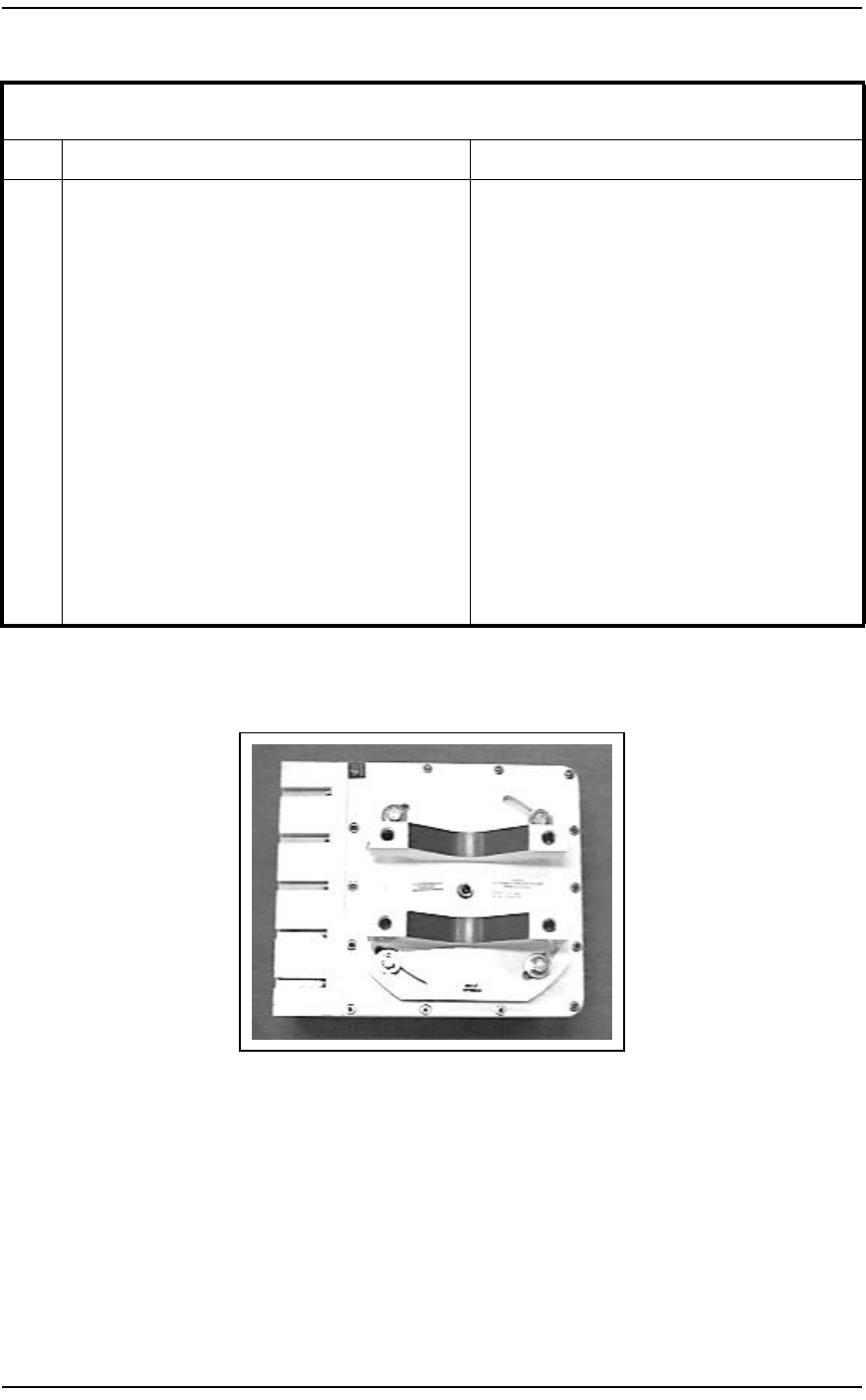
1Install the mounting bracket to the back of the
BTR using the five screws provided. Refer to Figure 8.
2Now place the 7/16th all thread bolts into the
back of the BTR mounting brackets.
Apply Antiseize to bolt threads.
Refer to Figure 9.
Procedure 2 – Installation of a BTR using a Fine Adjustment Bracket (Page 4 of 4)
Step Action Observation

BWA - BTR and RPE Installation / 15
August 11, 2000 Method 08-0283
3Ensure the bolts are hand tightened firmly.
Note: Do not use tools to tighten. The threads
may be damaged.
Refer to Figure 9.
4Slide the U-Brackets on the bolts so that they
match the U-Bracket on the back of the BTR.
The U-shaped cutouts should face each other.
The mast will be placed between the U-shaped
cutouts.
Refer to Figure 10.
5Place the washers and the 7/16th nuts onto the
bolts.
Note: Do not tighten the nuts all the way down;
this is only temporary. These will be removed to
place on the antenna mast and then re-applied.
6The BTR is ready for installation.
7Verify the Antenna Mast (pole) is secured before
installation begins.
Note: It is the customer’s responsibility to
ensure the roof and antenna mast are structurally
adequate to meet all local, state and federal codes
under maximum wind loading conditions.
8Verify the proper directions at which the BTR(s)
antenna will be facing, making sure the fin array
(heat sink) is positioned away from external
barriers to allow heat dissipation through natural
convection and radiation.
Note: If there are objects in the way, check with
the Program Manager before installing the BTR.
Refer to the Engineering Package for Azimuth.
9Get into position for installing the BTR.
Observe ISM and BWA Fall Safety for climbing
and high rise work areas.
Note: Do not pull on the antenna at any time.
Be very careful not to hit or drop the BTR.
Hoisting should be done by two technicians.
Procedure 3 – Installing the BTR(s) Using a Single Mount Bracket (Page 2 of 3)
Step Action Observation
16 / BWA - BTR and RPE Installation
Method 08-0283 August 11, 2000
Figure 8 – Mounting Bracket on back of BTR
10 Remove the U-shaped brackets, so that the BTR
can be mounted to the mast.
Apply Antiseize to the area where the nuts will
be.
11 Slide the U-shaped brackets onto the all-thread
bolts, then slide a washer and nut onto each
all-thread bolt. Tighten each nut until the BTR is
secured to the mast.
BTR Mounted to the mast.
Refer to Figure 10 for a picture of mounting
brackets on the pole.
Note: Remove the bottom drain plug from the
antenna to allow for drainage of moisture
buildup. Make sure that the top drain plug
remains in the antenna and is secure.
12 Repeat step 1 through 11 for each BTR.
13 End of Procedure.
Procedure 3 – Installing the BTR(s) Using a Single Mount Bracket (Page 3 of 3)
Step Action Observation
BWA - BTR and RPE Installation / 17
August 11, 2000 Method 08-0283
Figure 9 – Back of BTR with All thread bolts
Figure 10 – U-Brackets
18 / BWA - BTR and RPE Installation
Method 08-0283 August 11, 2000
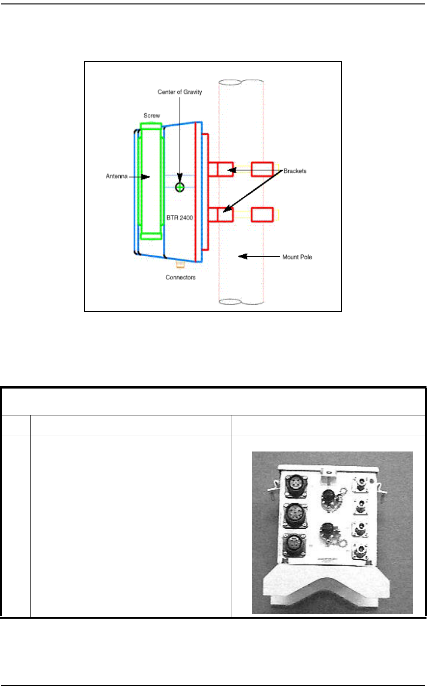
Figure 11 – Mounting BTR to the Antenna Mast
4.6 Install the RPE
This procedure will cover the installation of the RPE in a single BTR
mount configuration..
Procedure 4 – Install the RPE (Page 1 of 2)
Step Action Observation
1Attach RPE to the U-shape brackets with the four
allen screws and lock washers.
Note: Check in the Engineering Package on
placement of the RPE. The installation position
may vary at each location.
Note: Be very careful not to hit the RPE
connectors on anything. Hoisting/Installing
should be done by two technicians.
Bottom of RPE.
BWA - BTR and RPE Installation / 19
August 11, 2000 Method 08-0283
4.7 Installing the BTR(s) Using A Dual Mount Bracket.
The following procedure covers the assembly of the dual mount bracket
and BTR(s) to the antenna mast.
This procedure will require two technicians to perform.
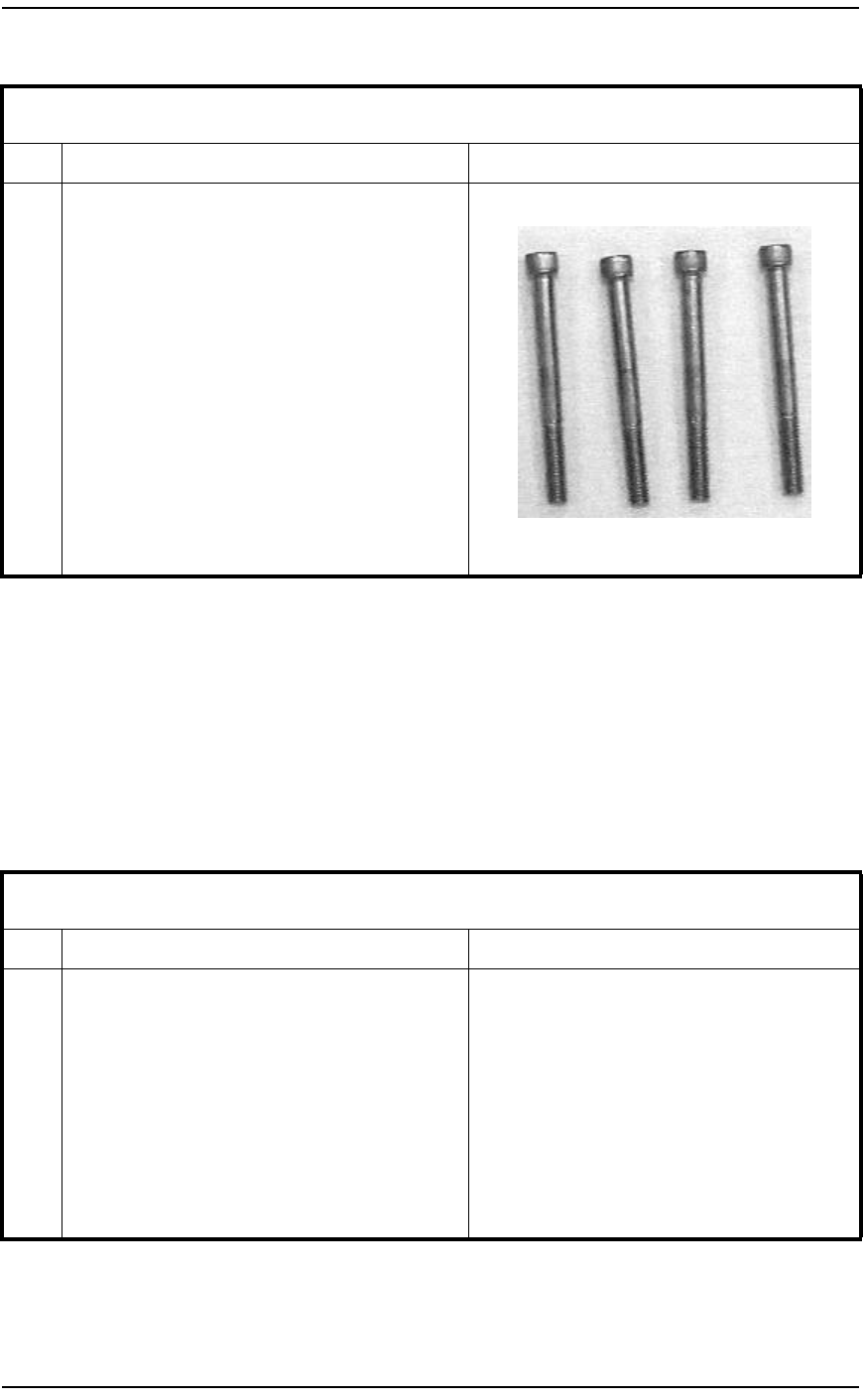
2Put the RPE up to the mast, align the U-brackets
and place the 5/16th Allen Head bolts through
the back side of the U-bracket so that the bolts
are supported by the bracket. Place the brackets
up to the mast and proceed to install the RPE to
the mast. Tighten the bolts down so that the RPE
is secured in position on the mast.
Note: Because the mast may vary in size, there
should be two lengths of bolts. Use the
appropriate bolts for the size mast being used.
5/16th bolts:
3End of Procedure.
Procedure 5 – Installing the BTR(s) Using A Dual Mount Bracket (Page 1 of 3)
Step Action Observation
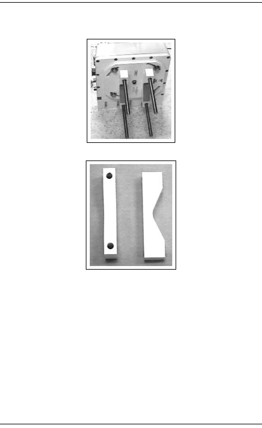
1Install the U-brackets (P0887173) onto the back
of the dual mount base assembly using the four
1/2" bolts, four 1/2" lock washers, and four 1/2"
flat washers. Tighten bolts.
Apply Antiseize.
2Screw two 1/2" by 6/14" long all threaded rods
into each clamp.
Apply Antiseize
Procedure 4 – Install the RPE (Page 2 of 2)
Step Action Observation

20 / BWA - BTR and RPE Installation
Method 08-0283 August 11, 2000
3The dual mount antenna bracket will need to be
installed on the antenna mast before the RPE or
the BTR(s) are installed to it. This will require
two technicians to install.
Note: The dual mount antenna bracket weighs
approximately 45 pounds. Be extremely careful
not to drop it.
4Carry the Dual Mount bracket and the Stabilizing
Collar to the roof location where it will be
installed.
5Install the Stabilizing Collar to the antenna mast
in order to provide support for the Dual Mount
bracket, making sure it is secure.
Apply Antiseize.
6Position the dual mount against the antenna mast
with the all thread bolt straddling the pole. The
dual mount bracket should be resting on the
stabilizing collar. Place the saddle supports
(P0890191) onto the all-thread bolts. Secure
them with a flat washer, lock washer, and a hex
head nut. Tighten them so that the dual mount is
secure.
Apply Antiseize where nuts will be tightened
down to.
Note: Remember that two BTR(s) and a RPE
will be mounted to the dual mount. Make sure
the mount is secure before mounting the BTR(s)
and the RPE.
Dual mount antenna bracket is secured to the
antenna mast.
7Prepare the RPE and the BTR(s) that will be
installed in the sectors.
Procedure 5 – Installing the BTR(s) Using A Dual Mount Bracket (Page 2 of 3)
Step Action Observation
BWA - BTR and RPE Installation / 21
August 11, 2000 Method 08-0283
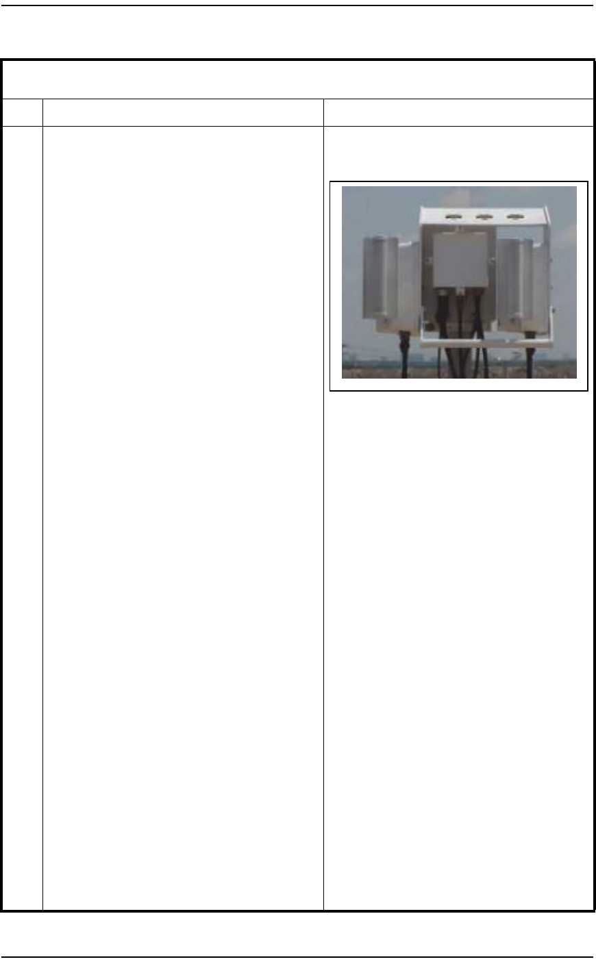
8The Primary BTR will be installed to the left and
outside (viewed from the front ) of the dual
mount. Place the top two screws and the center
screw in and secure the BTR to the dual mount.
Leave the bottom two screws out until told to
install.
Note: Top and center screws are shorter than
bottom screws.
The Primary BTR is installed to the left and
outside the dual mount antenna bracket.
9The RPE will be installed on the inside back
panel of the dual mount.
10 Place the RPE up to the back panel aligning the
holes. Use the four screws to secure the RPE to
the dual mount antenna bracket.
Refer to picture in step 8.
11 The Redundant BTR will be installed to the right
and inside (viewed from the front) of the dual
mount. Place the top two screws and the center
screw in and secure the BTR to the dual mount.
Leave the bottom two screws out until told to
install.
Note: Top and center screws are shorter than
bottom screws.
Refer to picture in step 8.
12 The handle assembly will now need to be
installed.
13 The handle assembly is mounted on the bottom
side of the base mount. The left side of the
handle mounts inside the base and the right side
mounts on the outside of the base.
Refer to picture in step 8.
14 Align the two holes up on each side and secure
the four screws for the handle assembly.
15 Repeat this procedure for each dual mount base
assembly being installed.
16 End of Procedure.
Procedure 5 – Installing the BTR(s) Using A Dual Mount Bracket (Page 3 of 3)
Step Action Observation

22 / BWA - BTR and RPE Installation
Method 08-0283 August 11, 2000
4.8 Alignment of BTR(s)
The line of sight alignment of the outdoor units is accomplished by
aligning the BTR(s) to an azimuth and elevation that define RF coverage
of that sector. The azimuth and elevation are located in the Engineering
Package.
This alignment procedure can be done using either single or dual BTR
mount configuration.
The following steps identify the procedure for aligning the BTR(s) to the
proper azimuth that is stated in the Engineering Package. The
fundamental aspect of this procedure is to align the BTR(s) using fixed
reference points (i.e. CPE(s) or Landmarks) and their associated
azimuth offset from the required pointing azimuth of the BTR(s). The
required elevation/tilt angle will be set using an inclinometer.
Procedure 6 – Alignment of BTR(s) (Page 1 of 4)
Step Action Observation
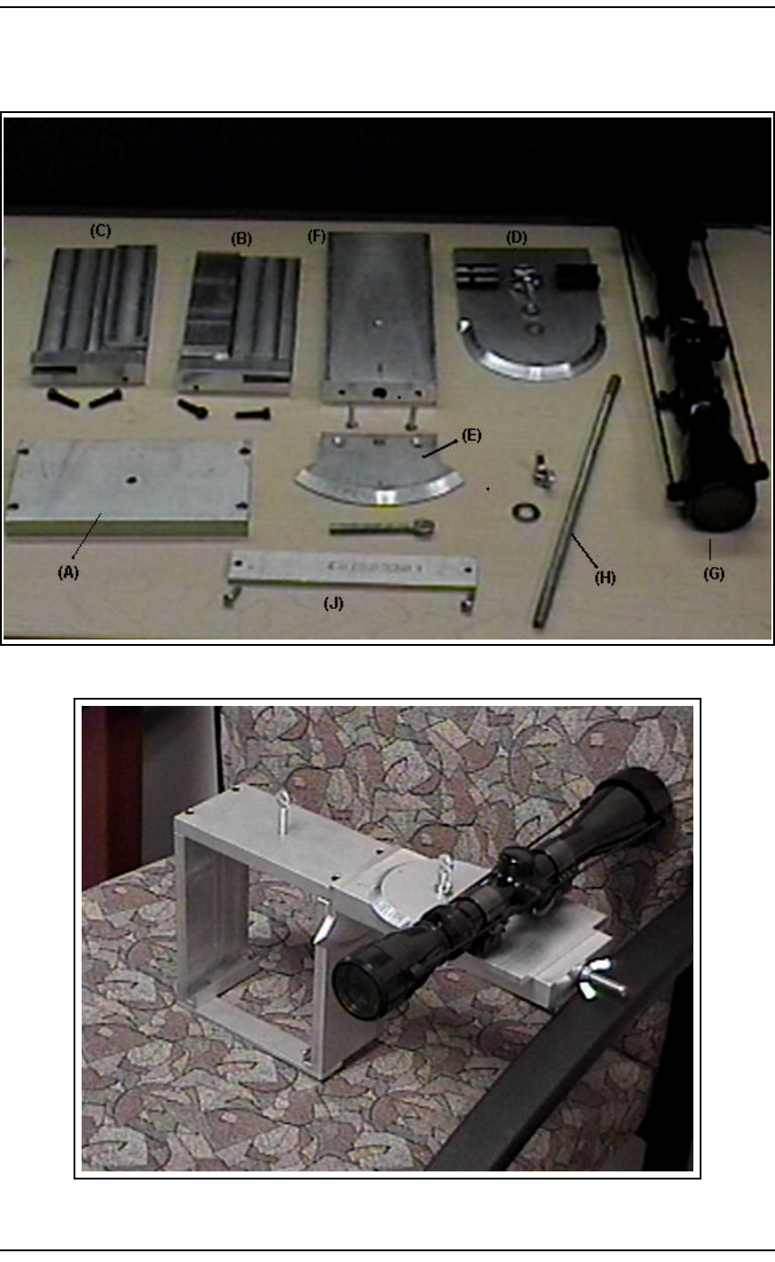
1The alignment tool must first be put together.
Steps 2 through 10 cover the assembly of the
alignment tool.
2Attach the long threaded rod (H) into the side of
the top bracket (A). The top bracket is the plate
with the counter-sunk screw holes in the top.
Refer to Figure 12 & 13.
3Hold the top bracket so that the threaded rod is
facing to the right and the counter sunk holes are
up. Attach the right side bracket (C) to the top
bracket using two 6/32 X 5/8 allen head screws
making sure the screws are flush with the top
bracket when installed. The right side bracket
should have the slots and the cut-down portion of
the brackets facing away from you when it is
installed onto the top bracket. You will also
notice there is a straight mark engraved on the
outside of the right bracket.
Refer to Figure 12 & 13.
4Hold the top bracket so that the threaded rod is
facing to the right. Attach the left side bracket
(B) to the top bracket using two 6/32 X 5/8 allen
head screws. The left side bracket should have
the slots and the cut-down portion of the brackets
facing away from you when it is installed onto
the top bracket. There is no straight mark
engraved on the outside of the left bracket.
Refer to Figure 12 & 13.

BWA - BTR and RPE Installation / 23
August 11, 2000 Method 08-0283
5Attach the tilt protractor (E) to the tilt/azimuth
bar (F) with two 8/32 flat head screws. Hold the
tilt/azimuth bar in your right hand so the
engraved straight line is up and to your left.
Place the tilt protractor (E) in your left hand so
the number slots are facing towards the right.
Using the flat head screws, secure the tile
protractor to the end of the tilt/azimuth bar (F).
Refer to Figure 12 & 13.
6Slide the tilt/azimuth bar (F) onto the threaded
rod so that the tilt protractor is set flush against
the right bracket (C). Secure the tilt/azimuth bar
(F) with a wingnut and washer so that the 0 on
the tilt protractor (E) is lined up with the
engraved mark on the right bracket (C).
Refer to Figure 12 & 13.
7Attach the azimuth protractor/scope platform (D)
to the tilt/azimuth bar (F) with the protractor
pointed to the engraved straight line on the tilt/
azimuth bar (F). Secure the azimuth protractor/
scope platform using the short 1/4-20
thumbscrew, wingnut and washer.
Refer to Figure 12 & 13.
8The bottom support bracket (J) will now need to
be attached to the right and left side brackets.
Turn the alignment tool upside down, using the
two small screws secure the support bracket on
the bottom of the right and left side brackets.
9Set the BTR attachment bracket so that it is to the
left and the azimuth protractor/scope platform to
the right. Attach the riflescope on the scope
mounts with the eyepiece towards you.
10 Screw the long 1/4-20 thumbscrew into the
threaded hole on the top bracket (A). The alignment tool is now installed and ready
to be used to align the BTR(s).
Refer to Figure 12 & 13.
11 Loosen the BTR(s) tilt and azimuth adjustment
so that it can be adjusted for tilt and azimuth
settings.
Procedure 6 – Alignment of BTR(s) (Page 2 of 4)
Step Action Observation

24 / BWA - BTR and RPE Installation
Method 08-0283 August 11, 2000
12 Locate the "BTR Antenna Alignment Using
Landmark" sheet within the Engineering
Package. Preset the azimuth offset from 0
degrees on the alignment tool by rotating the
scope plate to the left (if the azimuth offset is
negative) or to the right (if the azimuth offset is
positive) by the offset amount for the landmark
that is being used.
Azimuth is set.
Note: Each increment on the azimuth plate is 1
degree.
Note: Azimuth and tilt of the BTR is set by
using the relative position of one or more
landmarks (two are suggested, since two
landmarks would not have common errors to
the BTR).
Refer to Figure 14.
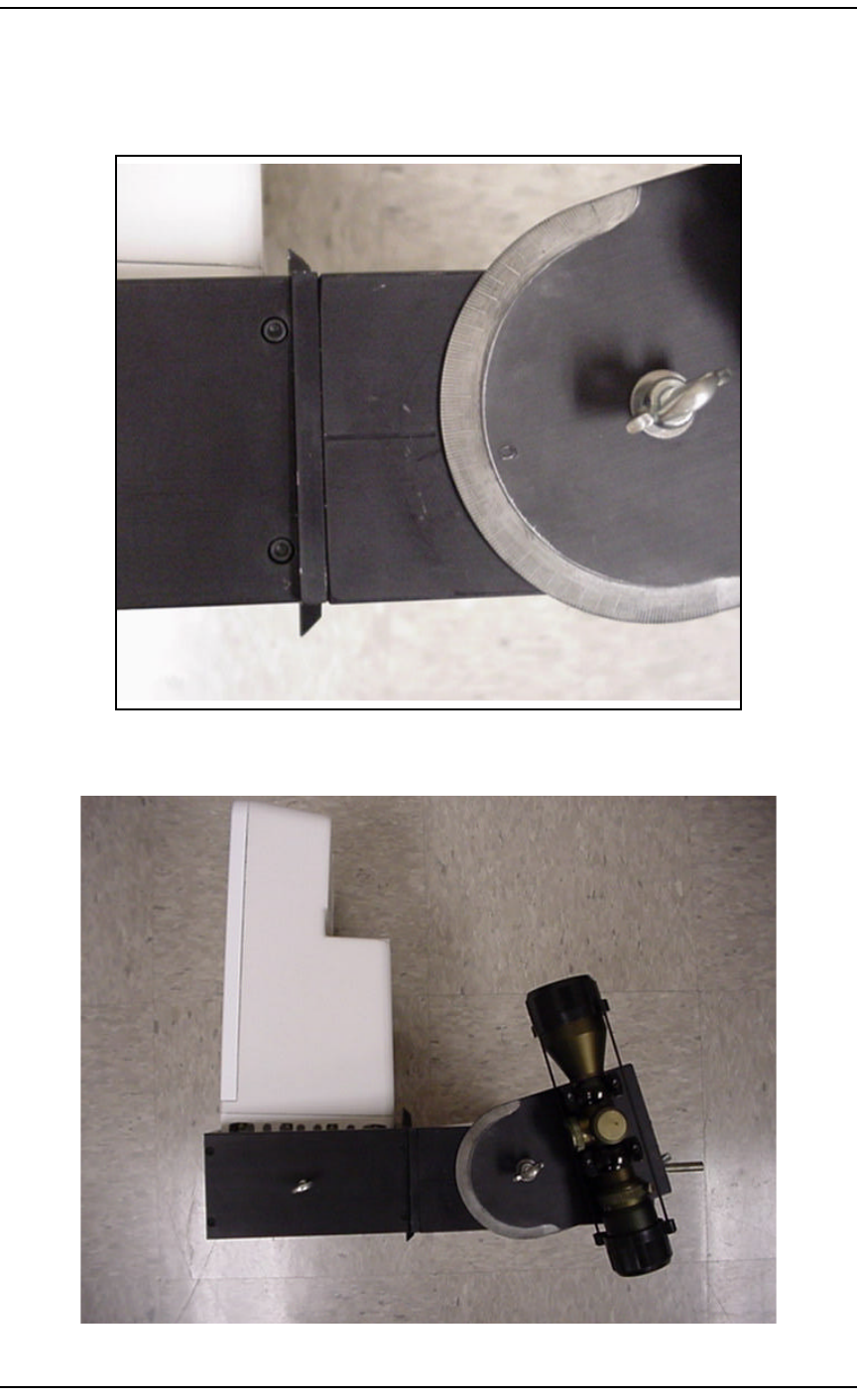
13 At the roof location, the alignment tool mounts
to the back of the BTR.
14 Slide the alignment tool over the heat sink so that
it fits flush, then tighten the long thumbscrew so
that is secures the alignment tool to the BTR.
Refer to Figure 15.
15 Adjust the BTR until the landmark point is in the
center of the crosshairs of the scope.
16 Now the Tilt will need to be set.
Note: The inclinometer has two scales on the
device. The one on the left shows actual degrees,
and the one on the right shows a percentage used
in calculating distance to target. USE THE
SCALE ON THE LEFT FOR BTR
ALIGNMENT.
Note: The proper BTR Tilt can be found in the
Engineering Package.
17 Place the inclinometer on the heat sink fins on
the back of the BTR.
Take a reading with the inclinometer using the
proper scale.
Note: Do not place your eye up against the
inclinometer. Look at the reading from 4 to 8
inches away from the inclinometers viewing
window.
Note: Line up the RED center indicator with
the BLACK angle identifier in the viewing
window of the inclinometer.
18 Adjust the BTR as needed and snug the bolts on
the BTR tilt adjustment clamps.
19 Recheck the tilt, repeating steps 17 and 18.
20 Tighten the BTR tilt and azimuth adjustment
clamps.
Procedure 6 – Alignment of BTR(s) (Page 3 of 4)
Step Action Observation

BWA - BTR and RPE Installation / 25
August 11, 2000 Method 08-0283
21 Verify the landmark is still in the crosshairs. If it
is not, redo steps 15 and 20.
22 Loosen the azimuth and tilt adjustment on the
alignment tool and rotate the scope to the center
of the second selected CPE in the scope
crosshairs.
23 Tighten the tilt and azimuth adjustment bolts on
the alignment tool.
24 Read the azimuth offset from 0 degrees to the
second landmark (if available). If the measured
azimuth offset matches the Engineering Package
value, the alignment is complete.
Note: If they are not, then one or the other (or
both) of the landmarks have bad survey data
(either lat/long or building height or both). To
determine the landmark with the bad data, select
a third landmark and follow steps 15 thru 21.
The two landmarks that agree must be considered
as correct, since the odds of having a common
data error at two different landmarks are very
small. At this point, the landmark with bad data
should have its tilt and azimuth offsets measured
(steps 15 thru 21) and the results recorded on the
offset data sheet and advise the RF Engineer of
this. If two of the three selected landmarks do
not agree with predicted offset from the BTR,
then the RF Engineer should be contacted for a
solution. The CPE with measured offsets that are
different from the expected offsets must be
highlighted for link budget corrections for the tilt
and azimuth offsets.
25 Repeat this procedure as necessary for all BTRs.
26 End of Procedure.
Procedure 6 – Alignment of BTR(s) (Page 4 of 4)
Step Action Observation
26 / BWA - BTR and RPE Installation
Method 08-0283 August 11, 2000
Figure 12 – Alignment Tool Parts
Figure 13 – BTR Alignment Tool
BWA - BTR and RPE Installation / 27
August 11, 2000 Method 08-0283
Figure 14 – Azimuth Plate
Example of the alignment tool set at a (-10) degree offset.
Figure 15 – Alignment Tool mounted to the BTR

28 / BWA - BTR and RPE Installation
Method 08-0283 August 11, 2000
5.0 References
There were no references used.

BWA - BTR and RPE Installation / 29
August 11, 2000 Method 08-0283
6.0 Appendices
Appendix A - Acronyms
Last Page
BTR Base Station Transceiver
BWA Broadband Wireless Access
ESD Electrostatic Sensitive Device
ETAS Emergency Technical Assistance Services
ISM Installation Safety Manual
JSIP Job Start Information Package
NNE Network Node Equipment
TAC Technical Assistance Center