Avaya Canada BTS18000 GSM 18000 BTS User Manual reference manual 160 15 01 prel
Avaya Canada Corporation GSM 18000 BTS reference manual 160 15 01 prel
UserManual.wiki
>
Avaya Canada
>
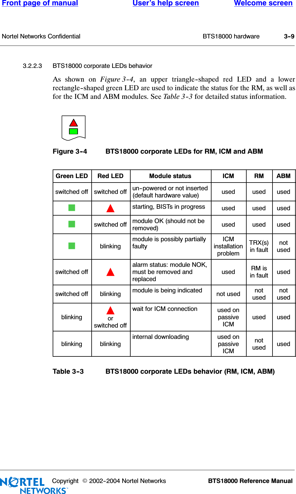
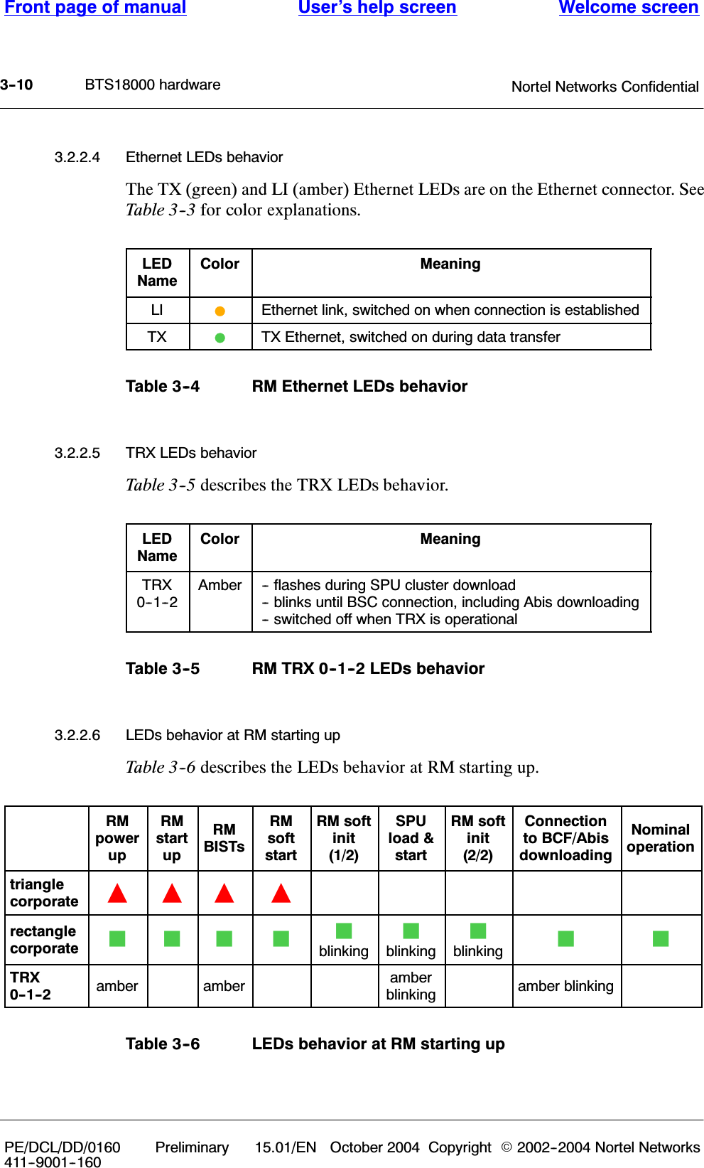
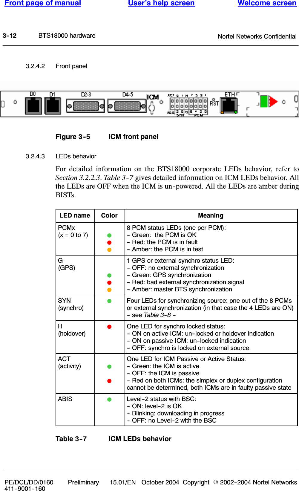
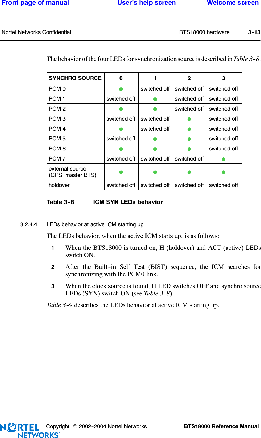
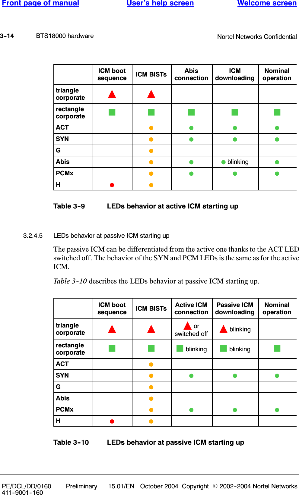
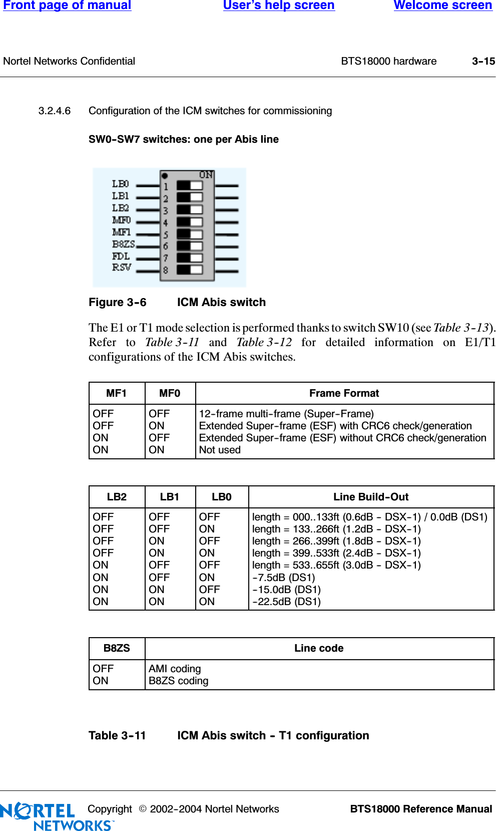
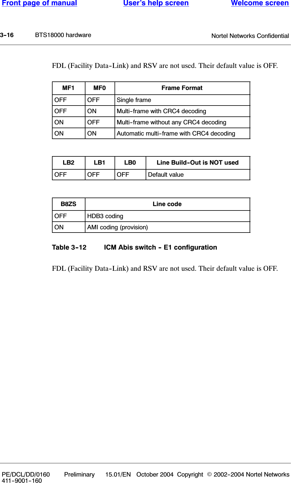
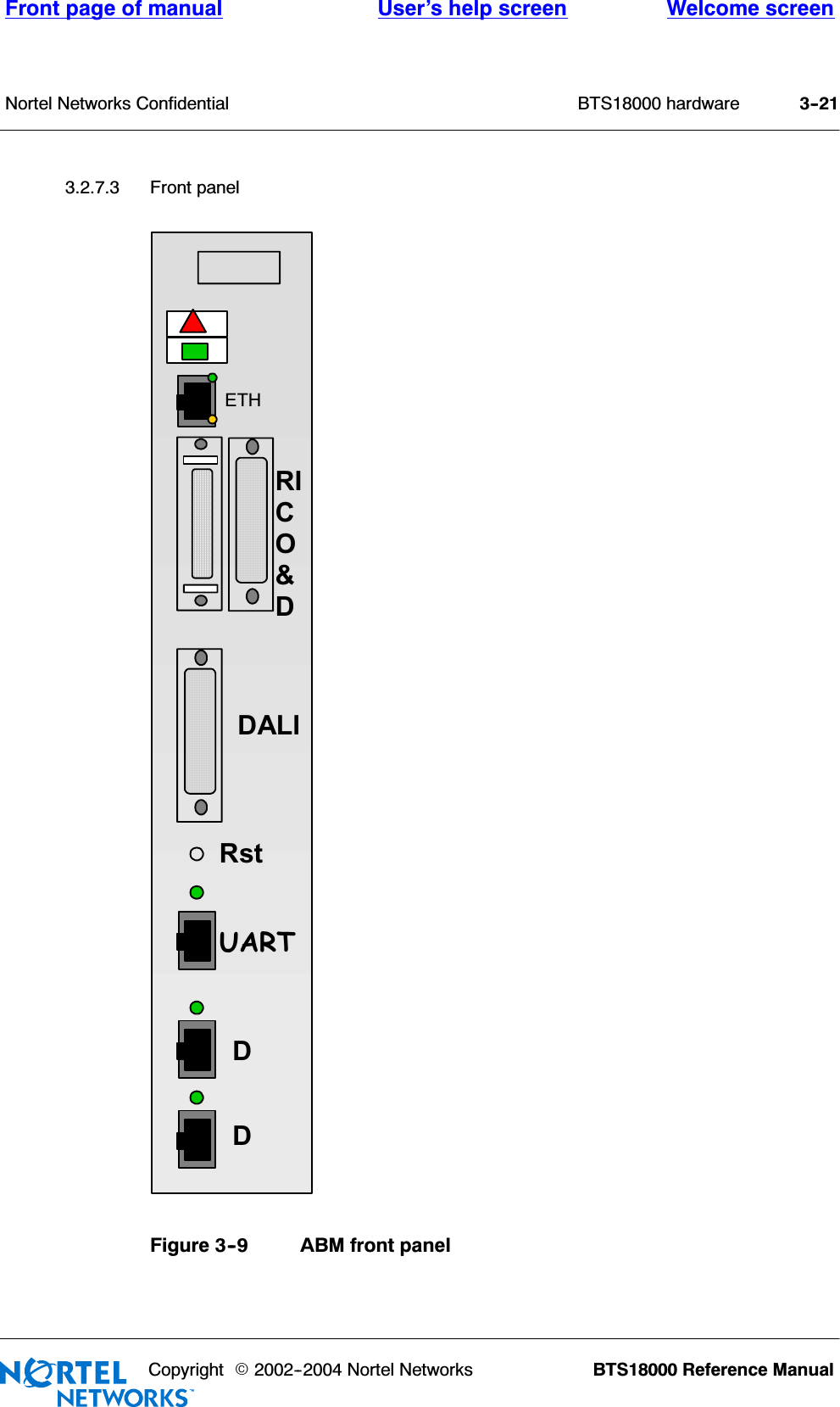
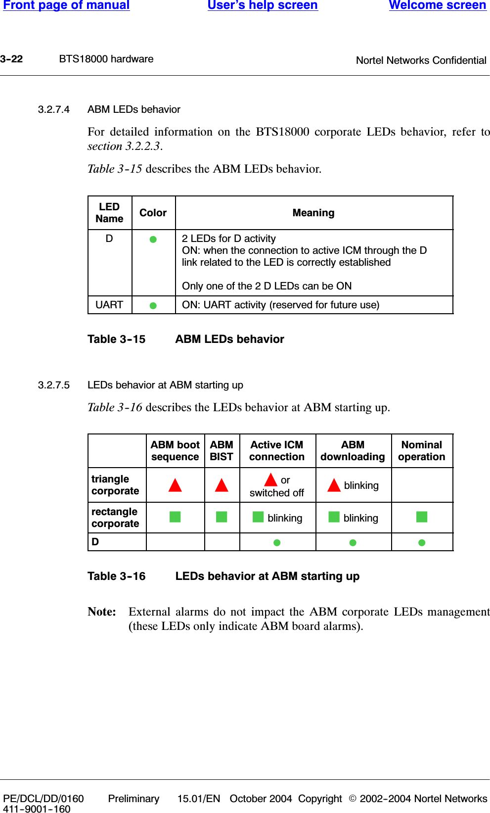
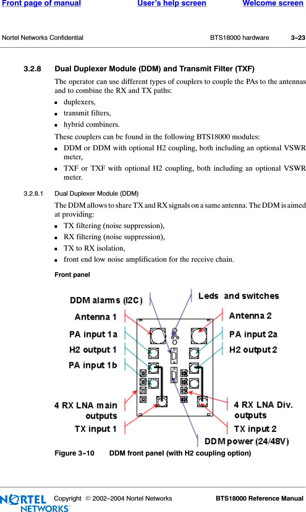
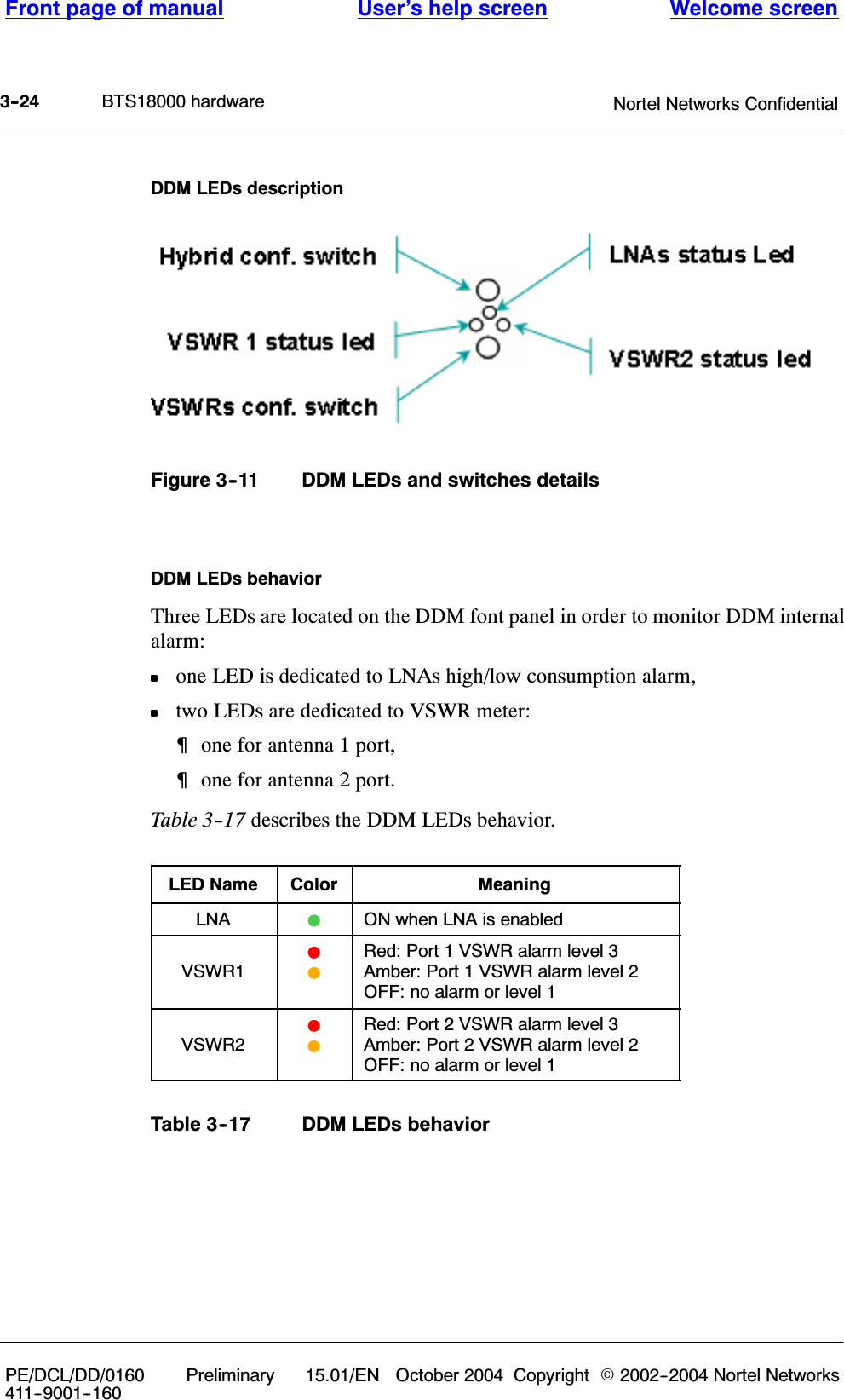
BTS18000 User Manual
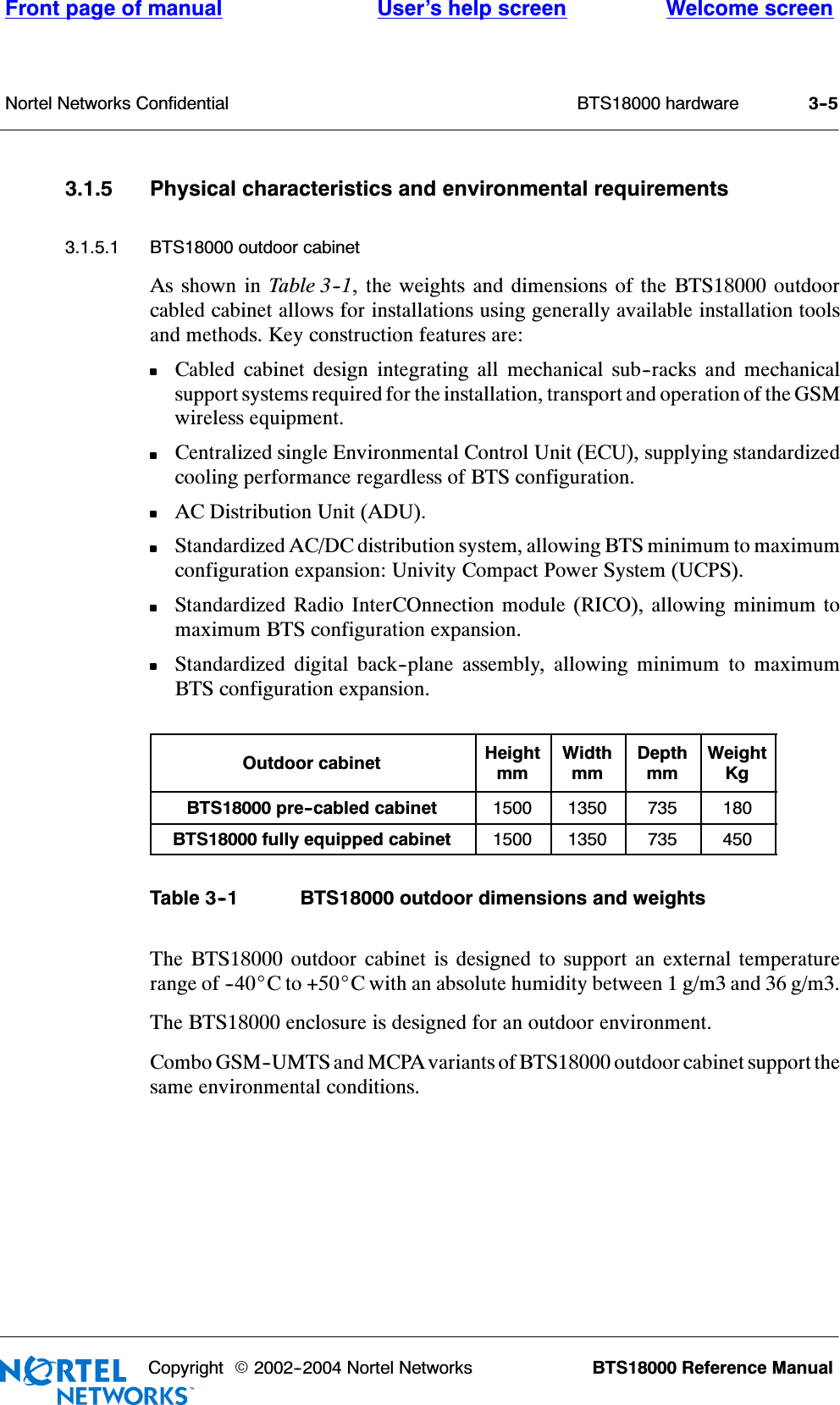
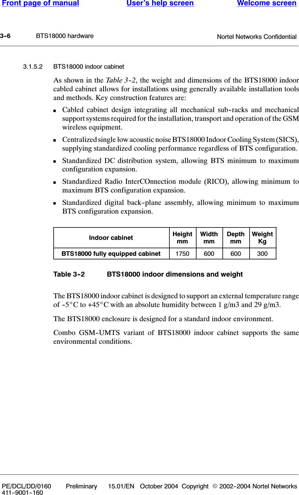
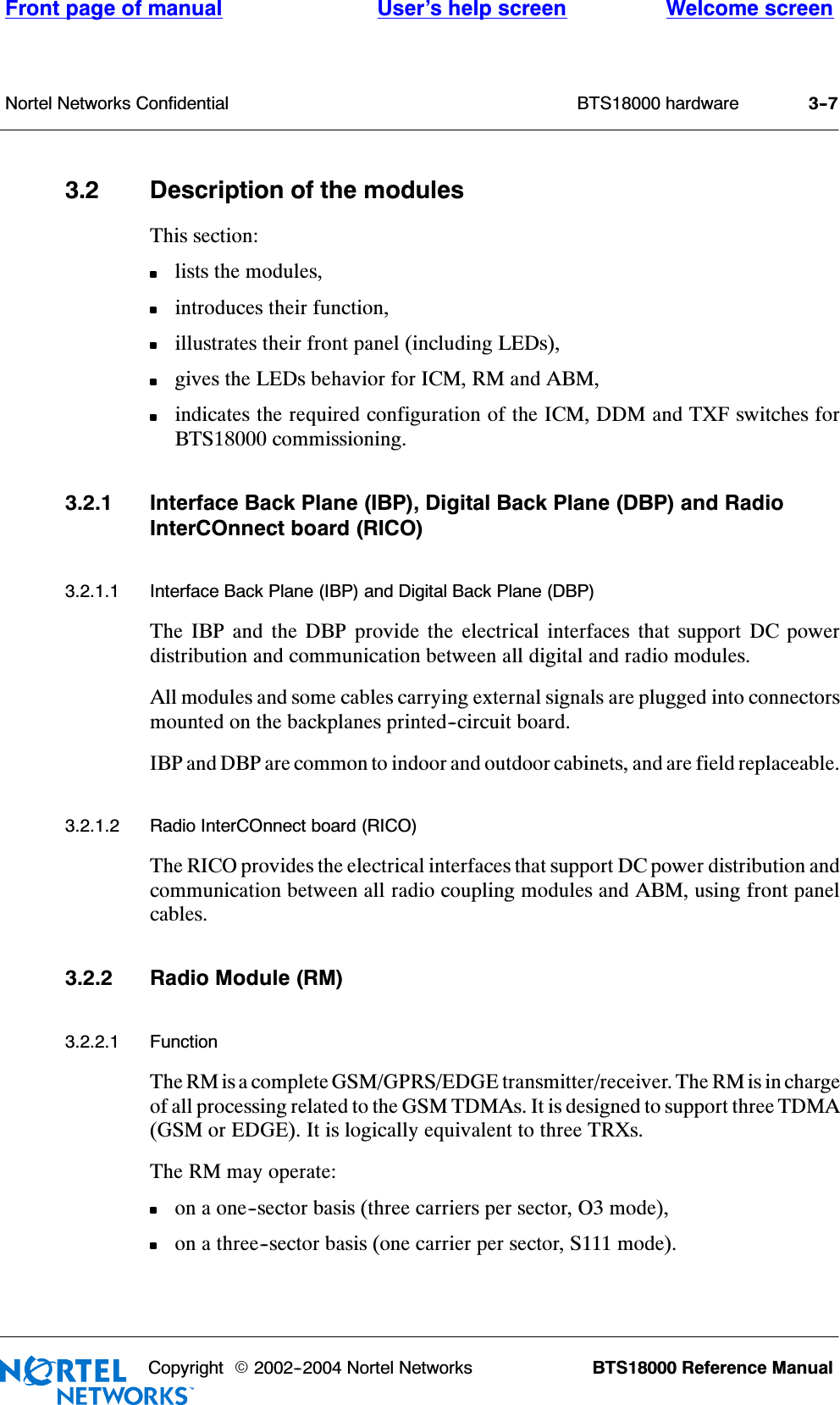
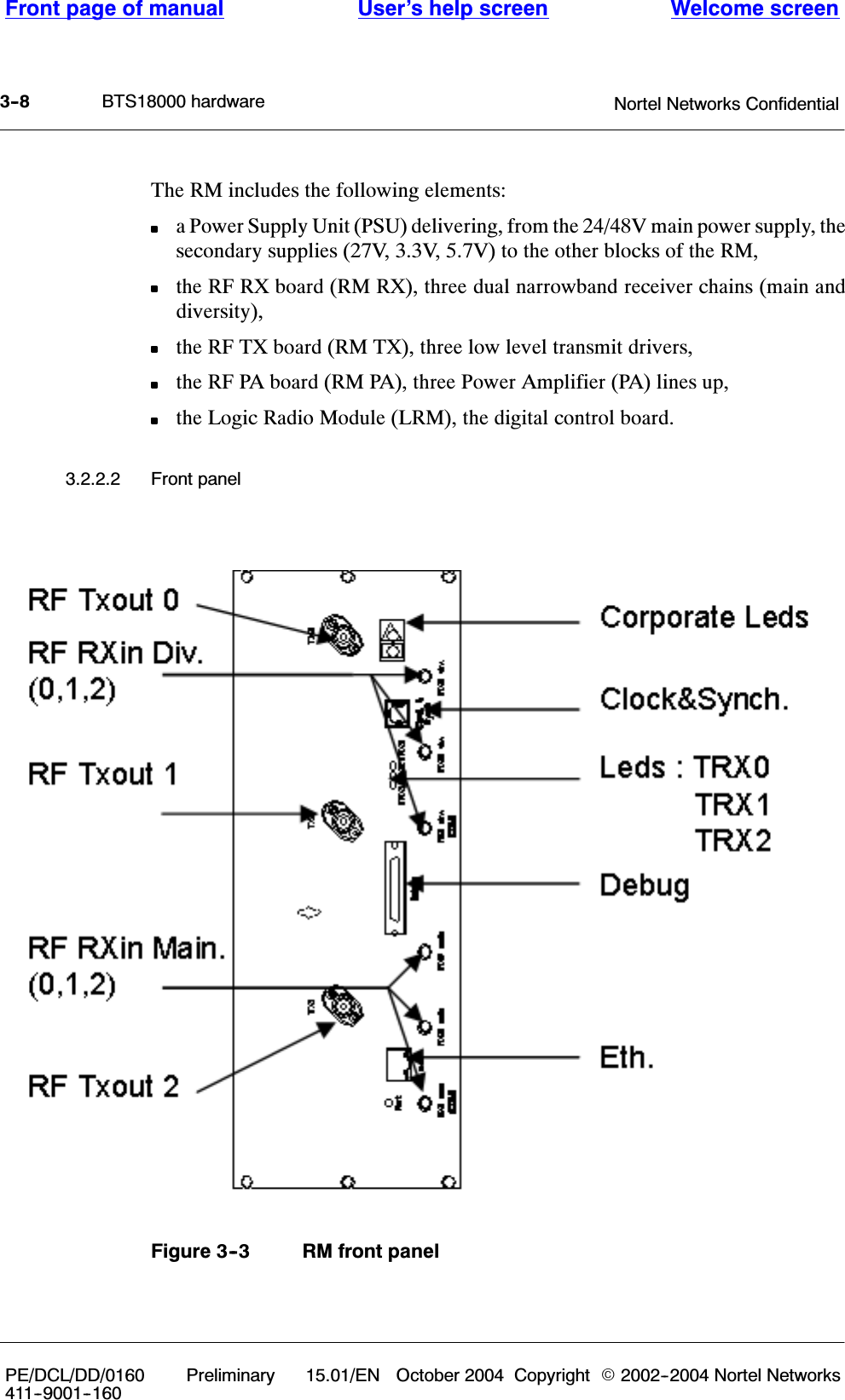
Exhibit 8 Manual
Navigation menu
Upload a User Manual
Namespaces
Wiki Guide
HTML
PDF
Info
Views
User Manual
Discussion / Help
Navigation