Avaya Canada BTS18000 GSM 18000 BTS User Manual reference manual 160 15 01 prel
Avaya Canada Corporation GSM 18000 BTS reference manual 160 15 01 prel
Exhibit 8 Manual
< 142 > : BTS18000 Reference Manual
Wireless Service Provider Solutions
BTS18000 Reference Manual
Document number: PE/DCL/DD/0160
411--9001--160
Document status: Preliminary
Document issue: 15.01/EN
Product release: GSM/BSS V15.0.1
Date: October 2004
Welcome screen
Table of contents
List of figures
List of tables
Copyright ¤2002--2004 Nortel Networks, All Rights Reserved
Originated in France
NORTEL NETWORKS CONFIDENTIAL:
The information contained in this document is the property of Nortel Networks. Except as specifically authorized in
writing by Nortel Networks, the holder of this document shall keep the information contained herein confidential and
shall protect same in whole or in part from disclosure and dissemination to third parties and use for evaluation,
operation and maintenance purposes only.
You may not reproduce, represent, or download through any means, the information contained herein in any way or in
any form without prior written consent of Nortel Networks.
The following are trademarks of Nortel Networks: *NORTEL NETWORKS, the NORTEL NETWORKS corporate logo,
the NORTEL Globemark, UNIFIED NETWORKS, S8000, S12000, BTS18000. GSM is a trademark of France Telecom.
Windows is a U.S. registered trademark of Microsoft Corp.
All other brand and product names are trademarks or registered trademarks of their respective holders.

Publication History
Front page of manual Welcome screenUser’s help screen
Nortel Networks Confidential iii
BTS18000 Reference Manual
Copyright E2002--2004 Nortel Networks
PUBLICATION HISTORY
System release: GSM/BSS V15.0.1
September 2004
Issue 15.01/EN Preliminary
Creation for feature 25808 -- BTS18000 introduction ready.

Table of contents
Front page of manual Welcome screenUser’s help screen
Nortel Networks Confidential
iv
PE/DCL/DD/0160
411--9001--160
Preliminary 15.01/EN October 2004 Copyright E2002--2004 Nortel Networks
About this document 0--1...............................................
Applicability 0--1......................................................................
Audience 0--1........................................................................
Prerequisites 0--1....................................................................
Related Documents 0--1...............................................................
How this document is organized 0--2....................................................
Vocabulary conventions 0--2...........................................................
Regulatory information 0--3............................................................
1 BTS18000 overview 1--1........................................
1.1 Key market trends 1--1......................................................
1.1.1 Operating expenses savings 1--1....................................
1.1.2 Advent of new technologies 1--1.....................................
1.1.3 Investment protection 1--2..........................................
1.1.4 Network coverage 1--2.............................................
1.2 Nortel Networks BTS portfolio 1--3............................................
1.2.1 Nortel Networks BTS18000 solution 1--3.............................
1.2.2 BTS18000 positioning in Nortel Networks BTS portfolio 1--4.............
1.3 BTS18000 offer 1--6.........................................................
1.3.1 BTS18000 versions 1--6............................................
1.3.2 BTS18000 possible uses 1--6.......................................
2 BTS18000 functionality 2--1.....................................
2.1 GSM--UMTS dual technology proposal 2--1.....................................
2.2 GSM features 2--1..........................................................
2.3 GSM functions 2--3.........................................................
3 BTS18000 hardware 3--1........................................
3.1 Description of the cabinets 3--1...............................................
3.1.1 BTS18000 outdoor cabinet layout 3--1...............................
3.1.2 BTS18000 indoor cabinet layout 3--2.................................
3.1.3 Power supply (outdoor cabinet) 3--4.................................
3.1.4 Cooling system 3--4...............................................
3.1.5 Physical characteristics and environmental requirements 3--5...........
3.2 Description of the modules 3--7...............................................
3.2.1 Interface Back Plane (IBP), Digital Back Plane (DBP) and Radio InterCOnnect board
(RICO) 3--7.......................................................

Table of contents
Front page of manual Welcome screenUser’s help screen
Nortel Networks Confidential v
BTS18000 Reference Manual
Copyright E2002--2004 Nortel Networks
3.2.2 Radio Module (RM) 3--7............................................
3.2.3 High Power Radio Module (HPRM) 3--11..............................
3.2.4 Interface Control Module (ICM) 3--11..................................
3.2.5 Interface Module (IFM) 3--19.........................................
3.2.6 Spare Module (SPM) 3--19..........................................
3.2.7 Alarms and Bridge Module (ABM) 3--19...............................
3.2.8 Dual Duplexer Module (DDM) and Transmit Filter (TXF) 3--23............
.............................................................
..........................................
......................
.......................................
..................................
..............................................
.........................................................
...............................................
..............................................
.............................
.........................................
................................
........................
.......................................
.....................................
.......................................
.............................................
...............................
...................................
.....................
...............................
.....................................
..................................................
...................................................
.................................................
.........................................................

List of figures
Front page of manual Welcome screenUser’s help screen
Nortel Networks Confidential
viii
PE/DCL/DD/0160
411--9001--160
Preliminary 15.01/EN October 2004 Copyright E2002--2004 Nortel Networks
Figure 1--1 BTS18000 positioning 1--4...............................................
Figure 3--1 BTS18000 outdoor equipped cabinet with door opened (front view) 3--2.......
Figure 3--2 BTS18000 indoor equipped cabinet with door opened (front view) 3--3.........
Figure 3--3 RM front panel 3--8.....................................................
Figure 3--4 BTS18000 corporate LEDs for RM, ICM and ABM 3--9......................
Figure 3--5 ICM front panel 3--12....................................................
Figure 3--6 ICM Abis switch 3--15....................................................
Figure 3--7 ICM SW10 switch 3--17..................................................
Figure 3--8 ICM SW11 switch 3--18..................................................
Figure 3--9 ABM front panel 3--21....................................................
Figure 3--10 DDM front panel (with H2 coupling option) 3--23.............................
Figure 3--11 DDM LEDs and switches details 3--24......................................
Figure 3--12 TXF front panel (with H2 coupling option) 3--26..............................
........................
..........
..............
...................
..................................
................................
..................................
......................
................
...............
............
...........................................
....................................................
...................................................
...................................................
...................................................
....................................................
............................
.............................
..................................................
...............................................
...............................................
..................................................

List of tables
Front page of manual Welcome screenUser’s help screen
Nortel Networks Confidential
x
PE/DCL/DD/0160
411--9001--160
Preliminary 15.01/EN October 2004 Copyright E2002--2004 Nortel Networks
Table 3--1 BTS18000 outdoor dimensions and weights 3--5............................
Table 3--2 BTS18000 indoor dimensions and weight 3--6..............................
Table 3--3 BTS18000 corporate LEDs behavior (RM, ICM, ABM) 3--9...................
Table 3--4 RM Ethernet LEDs behavior 3--10.........................................
Table 3--5 RM TRX 0--1--2 LEDs behavior 3--10.......................................
Table 3--6 LEDs behavior at RM starting up 3--10.....................................
Table 3--7 ICM LEDs behavior 3--12.................................................
Table 3--8 ICM SYN LEDs behavior 3--13............................................
Table 3--9 LEDs behavior at active ICM starting up 3--14...............................
Table 3--10 LEDs behavior at passive ICM starting up 3--14.............................
Table 3--11 ICM Abis switch -- T1 configuration 3--15...................................
Table 3--12 ICM Abis switch -- E1 configuration 3--16...................................
Table 3--13 ICM SW10 switch configuration 3--17......................................
Table 3--14 ICM SW11 switch configuration 3--18......................................
Table 3--15 ABM LEDs behavior 3--22................................................
Table 3--16 LEDs behavior at ABM starting up 3--22....................................
Table 3--17 DDM LEDs behavior 3--24................................................
Table 3--18 DDM switches configuration 3--25.........................................
Table 3--19 TXF LEDs behavior 3--26.................................................
Table 3--20 TXF switches configuration 3--27..........................................
Table 4--1 Memory size of flash EEPROM and RAM (for ICM, RM, ABM and UCPS) 4--15.
Table 5--1 RM output power per frequency band 5--15.................................
Table 7--1 UMTS configurations -- available main modes of operation 7--9...............
Table 8--1 BTS18000 corporate LEDs behavior (MRM, ICM, ABM) 8--5.................
Table 8--2 DLNA alarms levels and priority 8--8......................................

About this document
Front page of manual Welcome screenUser’s help screen
Nortel Networks Confidential 0--1
BTS18000 Reference Manual
Copyright E2002--2004 Nortel Networks
ABOUT THIS DOCUMENT
This document describes the new BTS18000 Base Transceiver Station (BTS),
which is a component of the Base Station Subsystem (BSS).
Applicability
This document applies to the V15.0.1 BSS system release.
Audience
This document is intended for operation and maintenance personnel, and for any
user who needs information relating to the BTS18000.
Prerequisites
It is recommended that the readers also become familiar with the following
documents:
< 000 > : BSS Product Documentation Overview
< 001 > : BSS Overview
< 007 > : BSS Operating Principles
< 039 > : BSS Maintenance Principles
< 124 > : BSS Parameter Dictionary
< 125 > : Observation Counter Dictionary
< 128 > : OMC--R User Manual -- Volume 1 of 3: Object and Fault menus
< 129 > : OMC--R User Manual -- Volume 2 of 3: Configuration, Performance, and
Maintenance menus
< 130 > : OMC--R User Manual -- Volume 3 of 3: Security, Administration,
SMS--CB, and Help menus
< 138 > : GSM BSS Engineering Rules
< 161 > : Fault Number Description: BTS18000
< 162 > : BTS18000 Maintenance Manual
Related Documents
The NTPs listed in the above paragraph are quoted in the document.

About this document
Front page of manual Welcome screenUser’s help screen
Nortel Networks Confidential
0--2
PE/DCL/DD/0160
411--9001--160
Preliminary 15.01/EN October 2004 Copyright E2002--2004 Nortel Networks
How this document is organized
Chapter 1 presents the new BTS18000 product and situatesit in the Nortel Networks
BTS portfolio.
Chapter 2 describes the BTS18000 functionality.
Chapter 3 describes:
the layout and content of the BTS18000 cabinets.
the functions of the BTS18000 boards and modules, as well as their front panels.
Chapter 4 describes the BTS18000 software.
Chapter 5 examines:
the BTS18000 functional architecture,
the BTS18000 hardware architecture.
Chapter 6 describes the GSM--UMTS dual mode configurations.
Chapter 7 describes the MCPA BTS18000 configurations.
Chapter 8 indicates that the dimensioning rules are now contained in NTP < 138 >
GSM BSS Engineering Rules.
Vocabulary conventions
The glossary is included in the NTP < 000 >.

About this document
Front page of manual Welcome screenUser’s help screen
Nortel Networks Confidential 0--3
BTS18000 Reference Manual
Copyright E2002--2004 Nortel Networks
Regulatory information
This part which provides the regulatory information concerning the BTS is split into
the following items:
European regulatory requirement compliance,
North American regulatory requirement compliance,
Compliances for other regions/countries,
Operation conditions,
Cable specifications,
Product labeling.
European regulatory requirement compliance
As a radio product, the Nortel Networks BTS18000 falls under the requirement of
the RTTE (Radio and Telecom Terminal Equipment) European directive
1999/5/EEC. The RTTE directive covers essential requirements in the field of:
protection of the Health and Safety of the user and any other person, including the
objectives with respect to safety requirements contained in the Low Voltage
directive (73/23/EEC).
the protection requirements with respect to EMC contained in Directive
89/336/EEC.
The equipment generates, uses, and can radiate radio frequency energy. If not
installed and used in accordance with the instruction manual, the equipment may
cause harmful interference to radio communications. However, there is no
guarantee that interference will not occur in a particular installation. If this
equipment does cause harmful interference to radio or television reception,
which can be determined by turning the equipment off and on, the user is
encouraged to try to correct the interference.
The EMC requirements have been selected to ensure an adequate level of
compatibility for apparatus at residential, commercial, and light industrial
environments. The levels however, do not cover extreme cases which may occur
in any location but with a low probability of occurrence. In particular, it may not
cover those cases where a potential source of interference which is producing
individually repeated transient phenomena, or continuous phenomena, is
permanently present, for example a radar or broadcast site in the near vicinity. In
such a case it may be necessary to either limit the source of interference, or use
special protection applied, to the interfered part, or both.
Note: For operation or maintenance inside Nortel Networks systems, the
antistatic wrist shall always be used to maintain the integrity of the
product.

About this document
Front page of manual Welcome screenUser’s help screen
Nortel Networks Confidential
0--4
PE/DCL/DD/0160
411--9001--160
Preliminary 15.01/EN October 2004 Copyright E2002--2004 Nortel Networks
effective use of the Radio spectrum allocated to terrestrial/space radio
communication and orbital resources so as to avoid harmful interference. The
routes and standards used to demonstrate compliance with there essential
requirements are outlined in the following paragraphs.
-- BTS EMC
Compliance with the essential requirements of EMC has been demonstrated using
EN301489--1 & --23 standard.
-- BTS radio compliance
Compliance with the essential requirements of effective use of the radio spectrum
has been demonstrated using EN301908--1 & --3 standard.
-- BTS safety
Compliance with the essential requirements of Safety has been demonstrated using
EN 60950 Standard.
-- BTS health protection
Compliance with the essential requirement of health requirement has been
demonstrated using EN50385.
North American regulatory requirements compliance
The Nortel Networks BTS18000 has been qualified according to North American
market requirements for the Outdoor and MCPA versions.
This equipment has been tested and found to comply with the limits for a Class B
digital device, pursuant to part 15 of the FCC Rules. These limits are designed to
provide reasonable protection against harmful interference in a residential
installation. This equipment generates, uses and can radiate radio frequency energy
and, if not installed and used in accordance with the instructions, may cause harmful
interference to radio communications. However, there is no guarantee that
interference will not occur in a particular installation. If this equipment does cause
harmful interference to radio or television reception, which can be determined by
turning the equipment off and on, the user is encouraged to try to correct the
interference by one or more of the following measures:
reorient or relocate the receiving antenna.
increase the separation between the equipment and receiver.
connect the equipment into an outlet on a circuit different from that to which the
receiver is connected.
consult the dealer or an experienced radio/TV technician for help.
-- BTS safety
Nortel Networks BTS18000 complies with UL60950 and CAN/CSA C22.2 No.
60950--00 Safety Standards. The CSA mark is applied on the BTS and demonstrates
compliance with both US and Canadian Standards.

About this document
Front page of manual Welcome screenUser’s help screen
Nortel Networks Confidential 0--5
BTS18000 Reference Manual
Copyright E2002--2004 Nortel Networks
-- BTS EMC and radio compliance
Nortel Networks BTS18000 complies with 47CFR Part 15 class B and 47 CFR Part
24 for EMC and radio emission limits according to US regulatory requirements as
indicated on the regulatory label.
-- BTS interconnection compliance
The Nortel Networks BTS18000 complies with 47 CFR Part 68 of the FCC rules
and the requirements adopted by the ACTA.
On the top right of this equipment is a label that contains, among other information,
a product identifier in the following format: US : AB6XDNANBTS18000
If requested, the following information must be provided to the telephonecompany:
FCC Registered Number: AB6.
Facility Interface Code (FIC): 04DU9.BN, 04DU9.DN, 04DU9.1KN, and
04DU9.1SN.
Service Order Code (SOC): 6.0F.
A FCC part 68 and ACTA compliant cable is provided with the BTS equipment,
with no connector at network interface side. The BTS equipment operates with a
1.544 Mbps digital channel. See Installation Instructions for details.
If the BTS18000 equipment causes harm to the phone network, the telephone
company will notify you in advance that temporary discontinuance of service may
be required. But if advance notice is not practical, the telephone company will notify
the customer as soon as possible. Also, you will be advised of your right to file a
complaint with the FCC if you believe it is necessary.
The telephone company may make changes to its facilities, equipment, operations
or procedures that could affect the operation of the equipment. If this happens the
telephone company will provide advance notice so you can make the necessary
modifications to maintain uninterrupted services.
If trouble is experienced with BTS18000 equipment, for repair or warranty
information, please contact:
Toy--Brent Lorance Nortel Networks
2370D Performance Dr.
Richardson, TX 75082
Phone: 972--685--2270
Fax: 972--684--7601
If the equipment is causing harm to the telephone network, the telephone company
may request that you disconnect the equipment until the problem is resolved.
All repairs should be handled by authorized Nortel Networks Service Personnel.
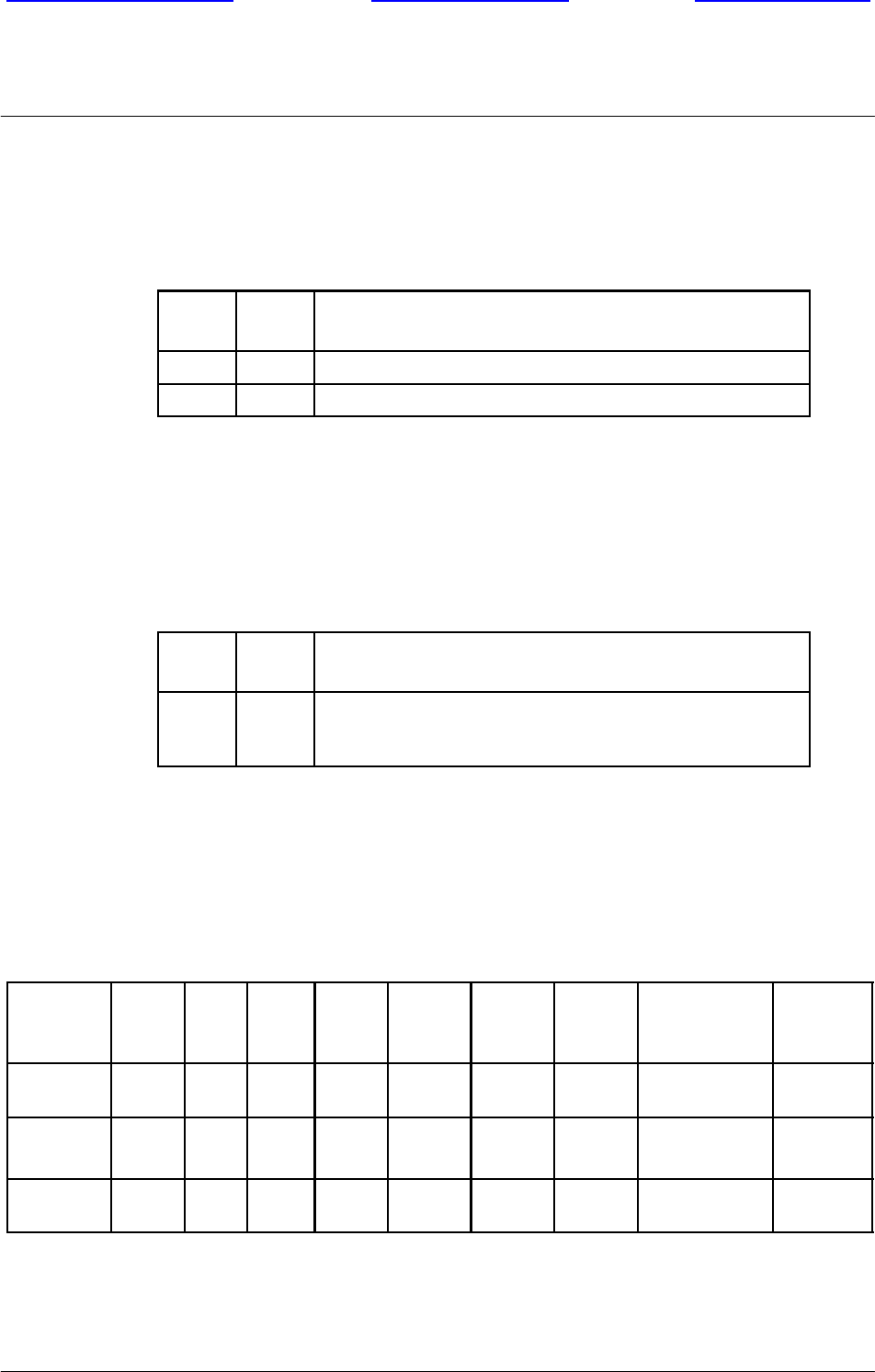
-- BTS18000 data equipment
The following table shows which jacks are associated with which modes of
operation.
About this document
Front page of manual Welcome screenUser’s help screen
Nortel Networks Confidential
0--6
PE/DCL/DD/0160
411--9001--160
Preliminary 15.01/EN October 2004 Copyright E2002--2004 Nortel Networks
Operation mode USOC Jack
Programmable & Test RJ45S
-- BTS18000 systems
Facility Interface Codes (FIC), Services Order Codes (SOC), USOC Jack Codes,
and Ringer Equivalence Number (REN) are shown in the table below for each port
where applicable.
Port FIC SOC USOC Jack REN
ICM T1 board 04DU9.BN 6.0F N/A N/A
ICM T1 board 04DU9.DN 6.0F N/A N/A
ICM T1 board 04DU9.1KN 6.0F N/A N/A
ICM T1 board 04DU9.1SN 6.0F N/A N/A
-- BTS18000 RF health protection
Compliance with the North American requirements is demonstrated through
calculation according to FCC OET bulletin 65.
Compliances for other regions/countries
For countries outside Europe and the Americas, the requirements of European
countries usually apply.
It is not possible to list all the applicable approvals/compliances as they will be
dependent on the markets and products considered.
Note: Please contact your local Nortel Networks representative for more
information.
Operational conditions
The aforementioned standards compliance of the products are based on the
following operating conditions (called normal operation):
doors shall be closed and (or) covers shall be in place.
external cables shall be of the same type as specified by Nortel Networks.
no modification of any mechanical or electrical characteristics of the product
shall be made.
Any change or modification made to the product without written approval from
Nortel Networks releases Nortel Networks from subsequent responsibility
regarding the standards compliance.
About this document
Front page of manual Welcome screenUser’s help screen
Nortel Networks Confidential 0--7
BTS18000 Reference Manual
Copyright E2002--2004 Nortel Networks
Cable specifications
The compliance to the aforementioned standards has been verified using cables as
specified by Nortel Networks. The continuing compliance of the product relies
upon use of the correct cabling scheme as well as use of identical type cables as
specified by Nortel Networks. Refer to the installation guides for details on cable
specifications.
Product labeling
The label may be located inside or outside the product, provided that the operation
and/or maintenance personnel have the information when working on the product.
-- BTS labeling for American Countries
To indicate compliance with the CSA and UL Safety requirements, the Nortel
Networks BTS18000 bears the following mark in a conspicuous location.
On the regulatory label, compliance to 47 CFR Part 15, 24 and 68 is stated along
with:
FCC ID, FCC Registration Number.
Manufacturers name.
Equipment designation.
Nominal voltage operating range and maximum rated current.
-- BTS labeling for European Countries
To indicate compliance with the European RTTE Directive, the Nortel Networks
BTS18000 bears the following information in a conspicuous location:
Manufacturers name.

About this document
Front page of manual Welcome screenUser’s help screen
Nortel Networks Confidential
0--8
PE/DCL/DD/0160
411--9001--160
Preliminary 15.01/EN October 2004 Copyright E2002--2004 Nortel Networks
Equipment designation.
Nominal voltage operating range and maximum rated current.
-- Labeling for other regions / countries
Labeling for other regions and countries is performed as appropriate and required
by the local regulatory framework.

BTS18000 overview
Front page of manual Welcome screenUser’s help screen
Nortel Networks Confidential 1--1
BTS18000 Reference Manual
Copyright E2002--2004 Nortel Networks
1 BTS18000 OVERVIEW
1.1 Key market trends
1.1.1 Operating expenses savings
Most of the operators in Europe and Asia are going to install UMTS equipment on
their networks, including UMTS radio cabinets. In most of the cases, these radio
equipments will be co--located with existing GSM sites.
Moreover, as GSM capacity increases in urban areas (voice and data traffic),
operators will need to install new radio transmitters and will be forced to limit the
number of additional radio cabinets required to carry the increasing traffic, in order
to contain the ”floor investments” at an acceptable level.
This results in a need for a Base Transceiver Station (BTS) solution with a high
number of transceivers per square meter, thus a cabinet which can house more TRXs
in the same footprint than S8000 and S12000 cabinets. This results as well in the
need for reduced power consumption, operational effectiveness, antenna tower
loading.
1.1.2 Advent of new technologies
The existing GSM European operators are almost all planning the deployment of
a 3G networks based on UMTS technology. Some of them have even started in 2001
but the massive deployment is just about to start.
In Asia, the scenario is almost the same and the Asian operators are also preparing
for 3G (CDMA 2000 or UMTS).
In the Americas, the path to 3G for GSM operators is likely to stop off at
GPRS/EDGE in a first stage with limited infrastructure investment before investing
massively in 3G technology.
The challenge for these operators is to increase the capacity and complete the
coverage of their GSM network while they are starting their investments in 3G
infrastructure. This results into two major difficulties for the operators:
Radio sites congestion.
Most of the urban sites are highly constrained by BTS footprint and will hardly
accommodate for both 3G and increased capacity GSM/GPRS base stations.
Therefore, dense and compact GSM and UMTS product solutions are required to
answer to this constraint.

BTS18000 overview
Front page of manual Welcome screenUser’s help screen
Nortel Networks Confidential
1--2
PE/DCL/DD/0160
411--9001--160
Preliminary 15.01/EN October 2004 Copyright E2002--2004 Nortel Networks
Financing and cash flow.
Investing in a new technology (3G), while break in GSM has not been reached,
will require very cost--effective product solutions. GSM radio sites will be
reused. Some solutions, as dual mode UMTS/GSM base stations and/or
infrastructure sharing between 3G operators, will allow cost--effectively
launching UMTS services, before smoothly migrating the subscriber base from
GSM to UMTS.
This results in a need for a BTS solution supporting both GSM and UMTS.
1.1.3 Investment protection
Most of the GSM operators are facing the challenges to increase the capacity and
coverage of their existing networks as traffic is growing, and in the same time start
to invest in new UMTS network elements and buy expensive licenses. As a
consequence, the protection of the operators’ existing investments while they invest
in new network components is becoming more and more important to preserve their
business profitability.
This results in a need for a BTS solution which should offer the maximum of
compatibility with the existing S8000 and S12000 BTSs installed on the field (e.g.
possibility to expand existing sites).
1.1.4 Network coverage
GSM coverage is not everywhere today and the GSM operators will complete the
coverage of their network in the coming years, mainly in not very dense and rural
areas.
This results in the need for a very cost--effective, low capacity solution, offering
high coverage capabilities in order to limit the investment and balance the business
case of the operator for the low revenue generating areas.

BTS18000 overview
Front page of manual Welcome screenUser’s help screen
Nortel Networks Confidential 1--3
BTS18000 Reference Manual
Copyright E2002--2004 Nortel Networks
1.2 Nortel Networks BTS portfolio
Combined with Nortel Networks’ experience gained through manufacturing and
delivering more than 540,000 DRX and 100,000 BTS to more than 54 countries and
100 operators throughout the world, the DRX--based family of BTS products
provides the operator with the key ingredients required to minimize both:
the initial and ongoing infrastructure investment,
the ongoing operating expenses.
The Nortel Networks family of BTS products offers the flexibility of high
performance and dense packaging needed to provide the operator with optimum
network solutions.
This BTS portfolio benefits from Nortel Networks’ vast experience in spectrum
management and network engineering.
1.2.1 Nortel Networks BTS18000 solution
The new BTS18000 is the Nortel Networks solution for all needs previously
described in section 1.1.
Nortel Networks new dual technology BTS18000:
leverages the latest capabilities that our UMTS and GSM/GPRS/EDGE
portfolios have to offer,
provides a flexible deployment platform for the rollout of UMTS services to
meet customer demand.
All this provides operators with a mean to control timing and costs for new UMTS
deployments.
The BTS18000’s flexibility also allows operating in a GSM--only mode that offers,
in a single cabinet, omni--directional O16 or tri--sectorial S666 capacities and is
scalable to a three cabinet site supporting a tri--sectorial S16.16.16 capacity.
BTS18000 overview
Front page of manual Welcome screenUser’s help screen
Nortel Networks Confidential
1--4
PE/DCL/DD/0160
411--9001--160
Preliminary 15.01/EN October 2004 Copyright E2002--2004 Nortel Networks
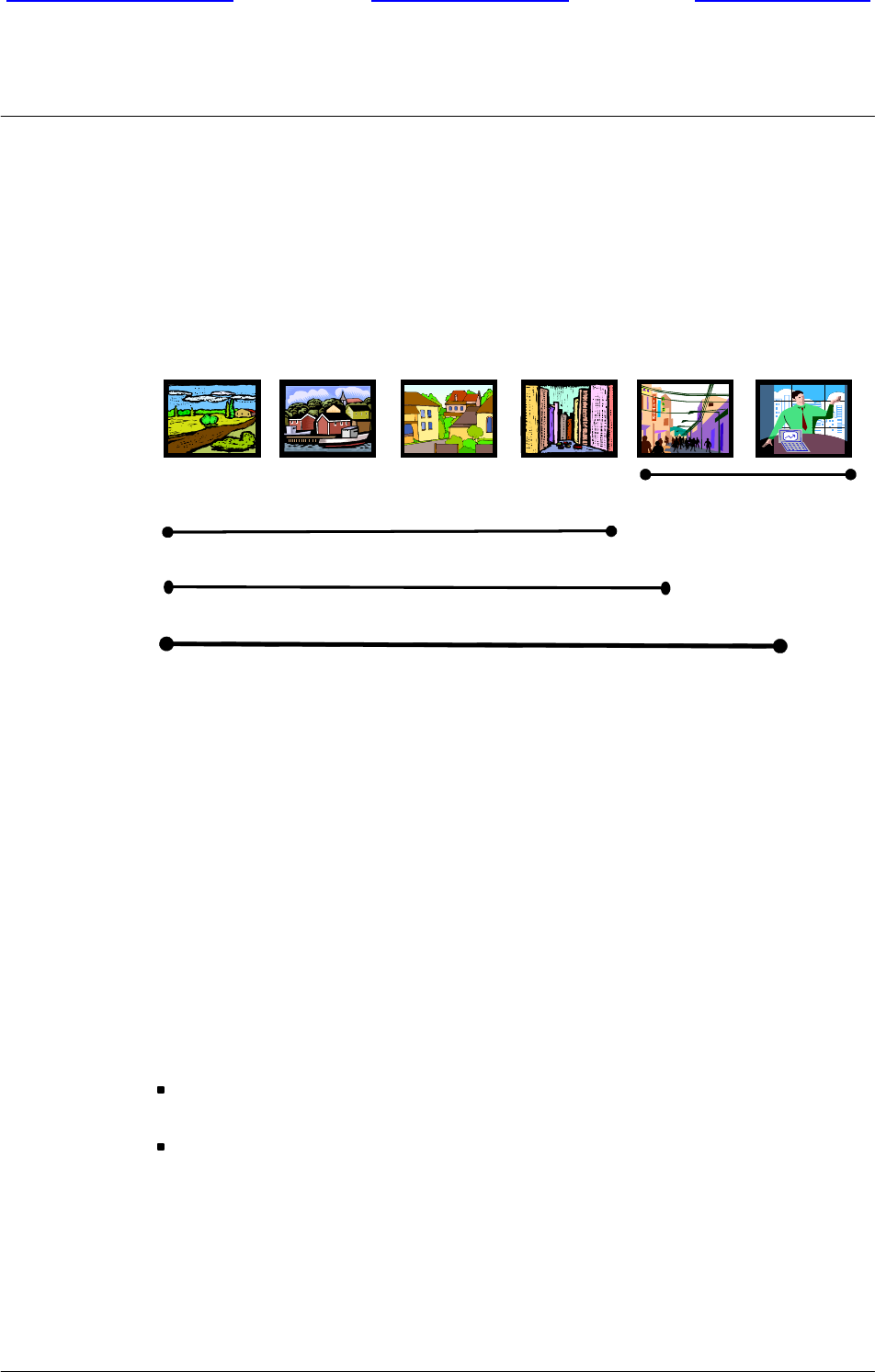
1.2.2 BTS18000 positioning in Nortel Networks BTS portfolio
Although a particular attention is paid on the high capacity configurations, the
BTS18000 is intended to cover almost all environments, from small towns (S111
type of configurations) up to indoor coverage (S16.16.16 and MCPA
configurations).
e-Cell
S12000 (S111-S12 12 12)
–
Rural
Small Towns
Highways Suburban IndoorUrban Dense Urban
S8000 (S111- S888)
BTS 18000 (S111-S18 18 18)
–
Rural
Small Towns
Highways Suburban IndoorUrban Dense Urban
Figure 1--1 BTS18000 positioning
In addition, the BTS18000 provides 3G evolution and GSM/EDGE Radio Access
Network (GERAN) readiness to Nortel Networks GSM macro base station
portfolio.
The Nortel Networks BTS portfolio includes the products listed below.
1.2.2.1 BTS18000
This new family of BTS is based on a new highly integrated Radio Module (RM)
that provides the equivalent of three GSM/GPRS/EDGE transceiver channels
including power amplifier function. This represents further integration of the
successful single module DRX approach for the receiver, transmitter and frame
processor, used in Nortel Networks legacy S8000 and S12000 BTSs.
The BTS18000 is an ideal site solution for operators:
that have well established GSM networks evolving to EDGE, with a need for
high density BTS in urban deployments,
that are planning new hybrid GSM/UMTS networks enabling more advanced
data services traffic.
These hybrid networks offer the ultimate balance of GSM and UMTS without
any compromises. The inherent flexibility of the new BTS is the catalyst to
accelerate today’s investment decision needed to secure the operator’s success
today and tomorrow.

BTS18000 overview
Front page of manual Welcome screenUser’s help screen
Nortel Networks Confidential 1--5
BTS18000 Reference Manual
Copyright E2002--2004 Nortel Networks
The BTS18000, which represents unprecedented capacity and flexibility, can
provide up to 54 TRX, with 18 TRX per sector, using only three cabinets.
1.2.2.2 S8000 BTS
The S8000 is a high performance BTS designed for macro--cellular voice and data
applications, that has a high modularity and expansion capability providing site
configurations ranging from 1 TRX to 8 TRX per sector in a tri--sectorial site, or
up to 16 TRX in an omni--directional configuration.
Because of its superior RF performance (high receiver sensitivity, interference
cancellation) and unique frequency re--use features, the S8000 BTS is an excellent
product that delivers wide coverage and optimizes spectrum efficiency. The S8000
BTS indoor version is designed for protected sites, while the outdoor version is a
fully integrated BTS site with AC power supply and extended temperature range.
1.2.2.3 S12000 BTS
The S12000 BTS is a twelve--transceivers, high--capacity solution designed to meet
the increasing traffic demand on macro cellular voice and future data applications.
The S12000 BTS can provide up to 36 TRX at a single site with 12 TRX per sector
using only three cabinets.
The S12000 BTS inherits the superior RF performances, unique features and main
modules of the S8000 BTS market--proven technology.
The modular design of S12000 BTS and the possibility to choose between multiple
RF--combining options allows the operator to deploy the S12000 solution in a
number of different scenarios such as a high--capacity solution in cities or
alternatively enabling to provide wide--coverage with a minimum number of sites
in rural areas. The S12000 BTS indoor version is designed for protected sites, while
the outdoor version is a fully integrated BTS site with AC power supply and
extended temperature range.
1.2.2.4 e--cell BTS
The e--cell BTS is the micro--BTS from Nortel Networks with a very light and
compact design. It is quick and easy to install. The e--cell unit includes two
transceivers and can be easily extendible to a synchronized four--transceiver BTS.
It is EDGE--ready and provides an ideal solution for indoor deployment as part of
a micro cellular underlay, or for in--building coverage.

BTS18000 overview
Front page of manual Welcome screenUser’s help screen
Nortel Networks Confidential
1--6
PE/DCL/DD/0160
411--9001--160
Preliminary 15.01/EN October 2004 Copyright E2002--2004 Nortel Networks
1.3 BTS18000 offer
1.3.1 BTS18000 versions
The BTS18000 is proposed in standard into two main versions:
BTS18000 indoor,
BTS18000 outdoor.
In addition to the two standard indoor and outdoor versions, the BTS18000 is
proposed in two variants:
Combo GSM/UMTS dual mode variant, proposed in indoor and outdoor
version,
MCPA variant, with increased number of TRXs per cabinet used in conjunction
with MCPA cabinet, proposed in outdoor version.
1.3.2 BTS18000 possible uses
The BTS18000, which is meant for various operating environments:
complements the S8000 or S12000 BTSs in Nortel Networks portfolio for
greenfield site deployments.
provides continuity to the S8000 and S12000 BTSs by its ability to be operated in
a synchronized co--location mode, to increase the capacity of existing S8000 or
S12000 sites.

BTS18000 functionality
Front page of manual Welcome screenUser’s help screen
Nortel Networks Confidential 2--1
BTS18000 Reference Manual
Copyright E2002--2004 Nortel Networks
2 BTS18000 FUNCTIONALITY
2.1 GSM--UMTS dual technology proposal
The BTS18000 is designed to integrate, within the same cabinet, both
GSM/GPRS/EDGE and UMTS technologies.
This configuration is available on all GSM frequency variants (850, 900, 1800, and
1900 MHz) and on both 1900 and 2100 MHz frequency variants for UMTS. The
maximum one--cabinet configuration is GSM S333 + UMTS STSR--2.
This configuration can support up to two additional GSM extension cabinets of 18
TRX. The maximum three--cabinet configuration is GSM S15.15.15 + UMTS
STSR--2.
2.2 GSM features
The BTS18000 offers a set of features enhancing the Quality of Service and the
spectrum efficiency of the network such as:
Full support of GPRS data services.
Full support of EDGE 8PSK modulation.
Guaranteed --110 dBm dynamic single--branch receive sensitivity (GMSK
modulation) at the BTS antenna, without any tower--mounted Low Noise
Amplifier (LNA).
Improved receiver diversity gain using a Nortel Networks specific algorithm,
providing 5 dB or more diversity gain in most situations, when spatial diversity
and de--correlated antennas are used.
High output power with a 30W or 45W standard Power Amplifier (PA), and an
optional 60W High Power Amplifier.
The BTS18000 cabinet can also be used as a very high density BTS in
conjunction with an optional cabinet housing Multi Carrier Power Amplifiers
(MCPA) and TX/RX antenna combiners.
The MCPA feature allows high radio capacities using fewer RF feeders
(8--Carriers per feeder at 43 dBm) and antennas:
xwithout the coverage penalties of hybrid combiner solutions,
xwithout the frequency hopping limitations of cavity combiner solutions.
The MCPA feature leads to a S16.16.16 configuration in two BTS cabinets and
one MCPA cabinet. The BTS18000 cabinet then contains up to 27 TRX without
power amplification. This BTS configuration is ideal for urban deployment with
severe space limitations and high capacity demands without compromising radio
coverage.

BTS18000 functionality
Front page of manual Welcome screenUser’s help screen
Nortel Networks Confidential
2--2
PE/DCL/DD/0160
411--9001--160
Preliminary 15.01/EN October 2004 Copyright E2002--2004 Nortel Networks
Dual--band GSM configurations with single--BCCH, built in a single or in
multiple BTS18000 cabinets.
Enhanced voice quality due to an innovative algorithm of interference
cancellation significantly reducing the end--user’s perception of errors generated
in the radio transmission.
Full RF power control range (static and dynamic).
Spectrum efficiency optimization with the support of the undisputed Nortel
Networks capacity features that provide high quality voice and data services to a
dense subscriber population, in a limited spectrum and at competitive cost.
These solutions include Fractional Frequency Reuse, Automated Cell Tiering
and Adaptive Multi Rate (AMR) support.
Best--in--class radio performance thanks to high sensitivity receivers, unique
interference cancellation and improved spatial diversity algorithms along with
high output power, providing optimum coverage and link quality for both data
and voice services.
High integration of advanced technology.
This in turn contributes to a significant reduction in required floor space, size and
equipment operating costs. This concept is adapted to stringent environmental
constraints and is leading to the best economic trade--off between initial and final
capacity.
In addition, the BTS18000 supports asymmetrical radio configurations such as
S963.
Compatibility with the S8000 and S12000 BTSs:
xthrough existing site synchronized co--location,
xthrough the possibility to re--use existing site equipment (such as an
S8000/S12000 outdoor plinth).
Industry leading transmission solution including high signaling concentration on
the Abis interface and drop--and--insert capability.
As an example, a single timeslot is only required for carrying the signaling of a
S333 BTS.
GSM/GPRS/EDGE and UMTS dual technology capabilities for operator
evolution to 3G data services.

BTS18000 functionality
Front page of manual Welcome screenUser’s help screen
Nortel Networks Confidential 2--3
BTS18000 Reference Manual
Copyright E2002--2004 Nortel Networks
2.3 GSM functions
The BTS18000 provides:
the radio interface with the mobile handsets,
the associated signal processing and the transmission interface with the Base
Station Controller (BSC).
The BTS18000 ensures the following main functions:
RF functions:
xAntenna coupling and duplexing,
xPower amplification,
xReception, including RF 2--way receive diversity,
xGaussian Minimum Shift Keying (GMSK) modulation/demodulation,
x8--Phase Shift Keying (8--PSK) EDGE modulation/demodulation,
xSynthesized frequency hopping in all hybrid coupling types.
Radio channel management:
xBTS and mobile handset power control,
xDiscontinuous Transmission and Voice Activity Detection (DTX/VAD), on
both uplink and downlink paths,
xRadio channel filling,
xCall setup and release,
xMobile timing advance processing,
xSupport of Enhanced Full--Rate (EFR), Full--Rate (FR), AMR Full--Rate and
AMR Half--Rate speech coding,
Signal processing:
xChannel encoding and decoding,
xEncryption (A5/2 and A5/1),
xEqualization,
xCancellation of interference,
xProcessing of radio measurements, including handover algorithms,
Interface with the BSC:
xCommunication with the BSC,
xConcentration of signaling on the Abis interface (a single PCM timeslot can
concentrate signaling for up to nine transceivers),
xMultiplexing of four traffic channels on one PCM slot (each TRX needs two
PCM slots for traffic),

BTS18000 functionality
Front page of manual Welcome screenUser’s help screen
Nortel Networks Confidential
2--4
PE/DCL/DD/0160
411--9001--160
Preliminary 15.01/EN October 2004 Copyright E2002--2004 Nortel Networks
xDynamic Abis for EDGE traffic,
xOptional optical OC--3/STM--1 connectivity.
Switching:
xConnection between the PCM links and the traffic/signaling channels,
xManagement of drop--and--insert connections,
xManagement of the TRX and PCM link redundancy.
Operation and Maintenance:
xHigh level of availability through optional duplication of switching,
synchronization and control unit (working in active/stand--by mode) and
optional N+1 redundancy for rectifiers and RM,
xMonitoring of internal and external alarms, through internal bus and alarm
loops,
xRemote configuration management from the BSC (site, sector, Abis, TRX),
xRemote software downloading.

BTS18000 hardware
Front page of manual Welcome screenUser’s help screen
Nortel Networks Confidential 3--1
BTS18000 Reference Manual
Copyright E2002--2004 Nortel Networks
3 BTS18000 HARDWARE
3.1 Description of the cabinets
This section presents the BTS18000 cabinet layout for both outdoor and indoor
versions.
For the outdoor version as well as for the indoor version, the BTS18000 cabinet
includes two shelves (see Figure 5--3 of Chapter 5 for a functional view of thesetwo
shelves). Each shelf contains:
one combiner rack,
one digital rack.
3.1.1 BTS18000 outdoor cabinet layout
The BTS18000 outdoor BTS can be housed in one or several cabinets depending
on the required capacity:
Only one cabinet is required (base cabinet), if the GSM capacity does not exceed:
x18 TRX, in GSM--only mode,
x9 TRX, in GSM--UMTS dual mode.
Up to two additional extension cabinets can be added. Each extension cabinet can
support up to 18 TRX.
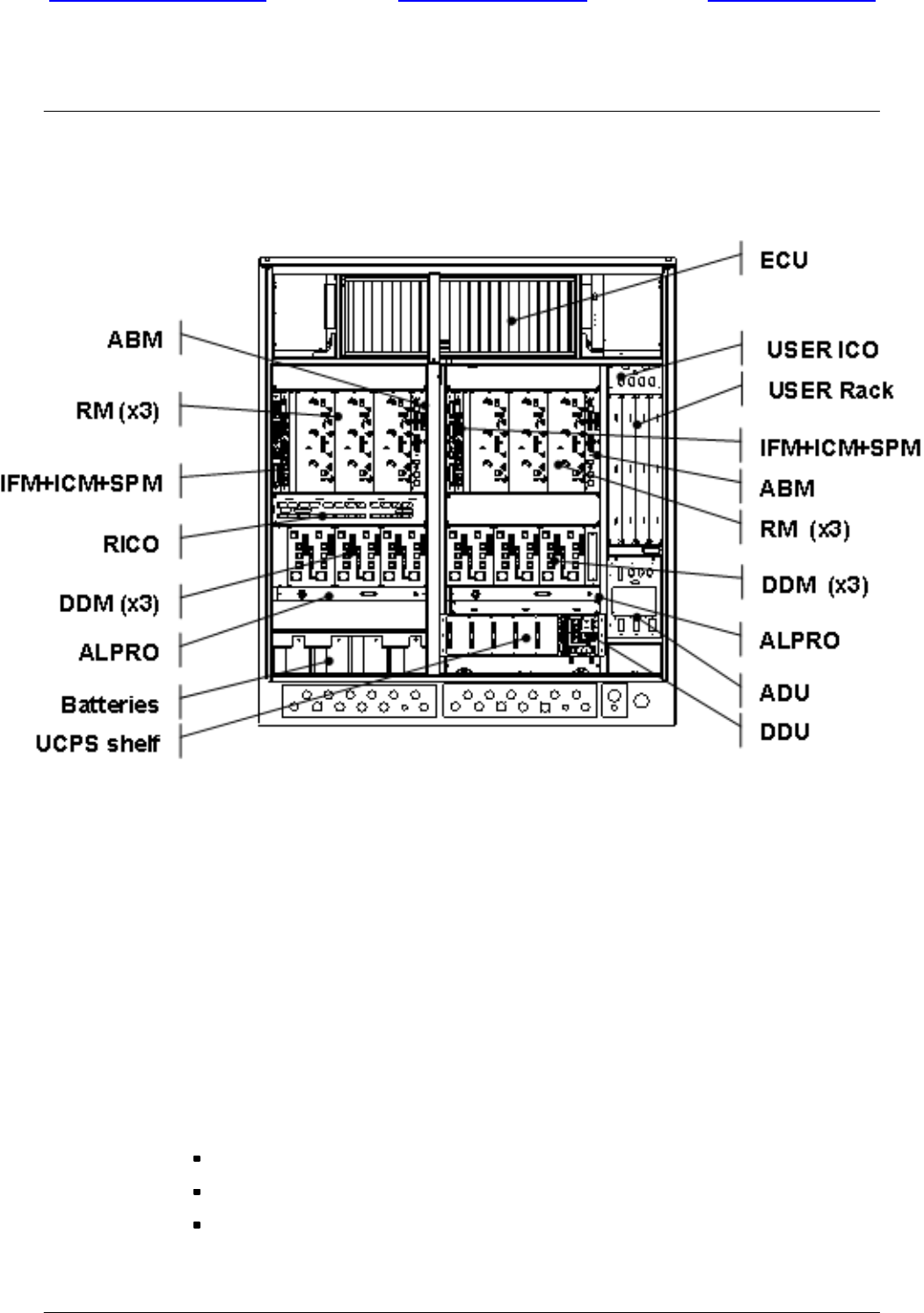
The BTS18000 outdoor cabinet includes the following elements:
outdoor enclosure including AC Distribution Unit (ADU),
AC/DC power supply: Univity Compact Power System (UCPS),
Environmental Control Unit (ECU),
User Rack space and its associated User ICO,
back--planes and ICO: Interface Back--Plane (IBP), Digital Back--plane (DBP),
Radio InterCOnnect board (RICO),
up to two Interface Modules (IFM),
one Interface Control Module (ICM) or two ICMs (in an active/passive
configuration, also called configuration with redundancy),
up to two SPare Modules (SPM),
up to two Alarm and Bridge Modules (ABM),
up to six Radio Modules (RM),
up to six Dual Duplexer Modules (DDM) with Voltage Standing Wave Ratio
(VSWR) meter.
BTS18000 hardware
Front page of manual Welcome screenUser’s help screen
Nortel Networks Confidential
3--2
PE/DCL/DD/0160
411--9001--160
Preliminary 15.01/EN October 2004 Copyright E2002--2004 Nortel Networks
Figure 3--1 presents the BTS18000 outdoor cabinet layout and situates the modules
in a fully equipped cabinet.
Figure 3--1 BTS18000 outdoor equipped cabinet with door opened (front view)
Note: The DDM modules are physically grouped into the two combiner racks.
Each digital rack consists of the association of IFM, ICM, ABM, SPM and
RM modules.
Note: IFM, ICM and SPM modules are not required in a BTS18000 extension
cabinet.
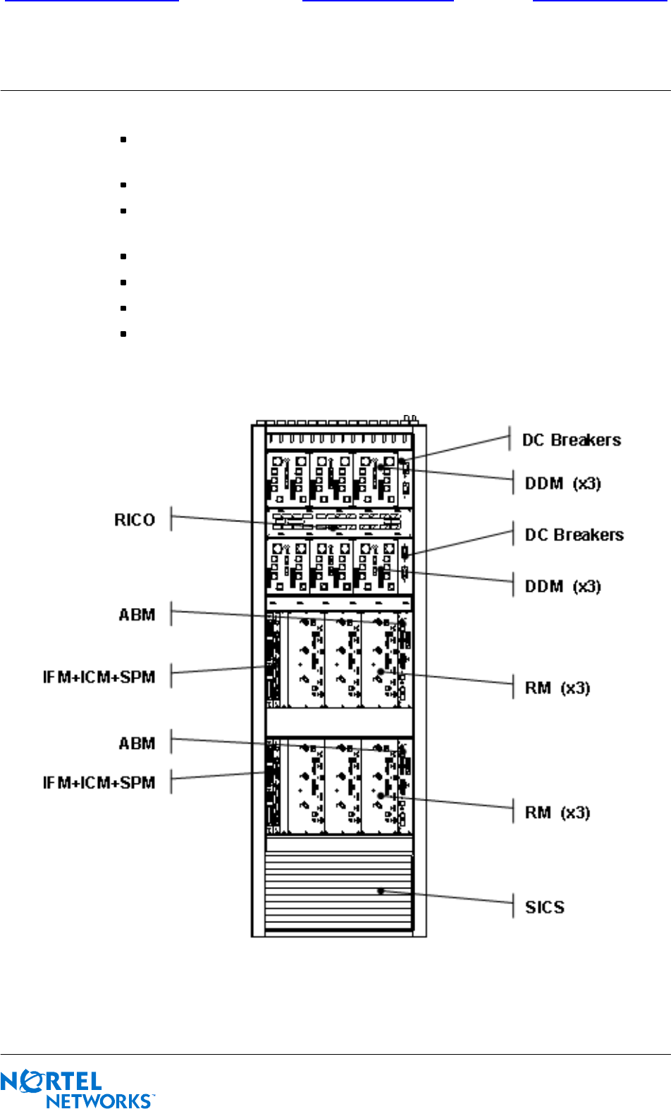
3.1.2 BTS18000 indoor cabinet layout
The BTS18000 indoor cabinet includes the following elements:
indoor enclosure,
DC breaker panel,
BTS18000 Integrated Cooling System (SICS),
BTS18000 hardware
Front page of manual Welcome screenUser’s help screen
Nortel Networks Confidential 3--3
BTS18000 Reference Manual
Copyright E2002--2004 Nortel Networks
back--planes and ICO: Interface Back--Plane (IBP), Digital Back--plane (DBP),
Radio InterCOnnect board (RICO),
up to two Interface Modules (IFM),
one Interface Control Module (ICM) or two ICMs (in an active/passive
configuration),
up to two SPare Modules (SPM),
up to two Alarm and Bridge Modules (ABM),
up to six Radio Modules (RM),
up to six Dual Duplexer Modules (DDM) with VSWR meter.
Figure 3--2 presents the BTS18000 indoor cabinet layout and situates the modules
in a fully equipped cabinet.
Figure 3--2 BTS18000 indoor equipped cabinet with door opened (front view)

BTS18000 hardware
Front page of manual Welcome screenUser’s help screen
Nortel Networks Confidential
3--4
PE/DCL/DD/0160
411--9001--160
Preliminary 15.01/EN October 2004 Copyright E2002--2004 Nortel Networks
3.1.3 Power supply (outdoor cabinet)
The outdoor cabinet provides an AC input. The AC Distribution Unit (ADU)
performs AC protection, filtering and distribution.
The UCPS power supply system delivers --48V DC voltage from the AC input.
The UCPS includes:
the rectifiers,
the DC Distribution Unit (DDU),
the Cabinet Control Unit (CCU).
3.1.4 Cooling system
3.1.4.1 BTS18000 outdoor cabinet
The outdoor cabinet design integrates the Environmental Control Unit (ECU). This
unit is installed at the top of the cabinet.
3.1.4.2 BTS18000 indoor cabinet
The indoor cabinet design integrates the BTS18000 Indoor Cooling System (SICS).
This system is installed at the bottom of the cabinet, and accessed through an access
lift off panel.
An electronic monitoring unit controls the cooling functions of the SICS.
This unit:
senses the internal cabinet air temperature and the external ambient air
temperature,
then selects the level of environmental control required to maintain full
operational performance of the electronic equipment installed within the indoor
cabinet.

BTS18000 hardware
Front page of manual Welcome screenUser’s help screen
Nortel Networks Confidential 3--5
BTS18000 Reference Manual
Copyright E2002--2004 Nortel Networks
3.1.5 Physical characteristics and environmental requirements
3.1.5.1 BTS18000 outdoor cabinet
As shown in Table 3--1, the weights and dimensions of the BTS18000 outdoor
cabled cabinet allows for installations using generally available installation tools
and methods. Key construction features are:
Cabled cabinet design integrating all mechanical sub--racks and mechanical
support systems required for the installation, transport and operation of the GSM
wireless equipment.
Centralized single Environmental Control Unit (ECU), supplying standardized
cooling performance regardless of BTS configuration.
AC Distribution Unit (ADU).
Standardized AC/DC distribution system, allowing BTS minimum to maximum
configuration expansion: Univity Compact Power System (UCPS).
Standardized Radio InterCOnnection module (RICO), allowing minimum to
maximum BTS configuration expansion.
Standardized digital back--plane assembly, allowing minimum to maximum
BTS configuration expansion.
Outdoor cabinet Height
mm
Width
mm
Depth
mm
Weight
Kg
BTS18000 pre--cabled cabinet 1500 1350 735 180
BTS18000 fully equipped cabinet 1500 1350 735 450
Table 3--1 BTS18000 outdoor dimensions and weights
The BTS18000 outdoor cabinet is designed to support an external temperature
range of --40_Cto+50_C with an absolute humidity between 1 g/m3 and 36 g/m3.
The BTS18000 enclosure is designed for an outdoor environment.
Combo GSM--UMTS and MCPA variants of BTS18000 outdoor cabinet support the
same environmental conditions.
BTS18000 hardware
Front page of manual Welcome screenUser’s help screen
Nortel Networks Confidential
3--6
PE/DCL/DD/0160
411--9001--160
Preliminary 15.01/EN October 2004 Copyright E2002--2004 Nortel Networks
3.1.5.2 BTS18000 indoor cabinet
As shown in the Table 3--2, the weight and dimensions of the BTS18000 indoor
cabled cabinet allows for installations using generally available installation tools
and methods. Key construction features are:
Cabled cabinet design integrating all mechanical sub--racks and mechanical
support systems required for the installation, transport and operation of the GSM
wireless equipment.
Centralized single low acoustic noise BTS18000 Indoor Cooling System (SICS),
supplying standardized cooling performance regardless of BTS configuration.
Standardized DC distribution system, allowing BTS minimum to maximum
configuration expansion.
Standardized Radio InterCOnnection module (RICO), allowing minimum to
maximum BTS configuration expansion.
Standardized digital back--plane assembly, allowing minimum to maximum
BTS configuration expansion.
Indoor cabinet Height
mm
Width
mm
Depth
mm
Weight
Kg
BTS18000 fully equipped cabinet 1750 600 600 300
Table 3--2 BTS18000 indoor dimensions and weight
The BTS18000 indoor cabinet is designed to support an external temperature range
of --5_Cto+45_C with an absolute humidity between 1 g/m3 and 29 g/m3.
The BTS18000 enclosure is designed for a standard indoor environment.
Combo GSM--UMTS variant of BTS18000 indoor cabinet supports the same
environmental conditions.

BTS18000 hardware
Front page of manual Welcome screenUser’s help screen
Nortel Networks Confidential 3--7
BTS18000 Reference Manual
Copyright E2002--2004 Nortel Networks
3.2 Description of the modules
This section:
lists the modules,
introduces their function,
illustrates their front panel (including LEDs),
gives the LEDs behavior for ICM, RM and ABM,
indicates the required configuration of the ICM, DDM and TXF switches for
BTS18000 commissioning.
3.2.1 Interface Back Plane (IBP), Digital Back Plane (DBP) and Radio
InterCOnnect board (RICO)
3.2.1.1 Interface Back Plane (IBP) and Digital Back Plane (DBP)
The IBP and the DBP provide the electrical interfaces that support DC power
distribution and communication between all digital and radio modules.
All modules and some cables carrying external signals are plugged into connectors
mounted on the backplanes printed--circuit board.
IBP and DBP are common to indoor and outdoor cabinets, and are field replaceable.
3.2.1.2 Radio InterCOnnect board (RICO)
The RICO provides the electrical interfaces that support DC power distribution and
communication between all radio coupling modules and ABM, using front panel
cables.
3.2.2 Radio Module (RM)
3.2.2.1 Function
The RM is a complete GSM/GPRS/EDGE transmitter/receiver. The RM is in charge
of all processing related to the GSM TDMAs. It is designed to support three TDMA
(GSM or EDGE). It is logically equivalent to three TRXs.
The RM may operate:
on a one--sector basis (three carriers per sector, O3 mode),
on a three--sector basis (one carrier per sector, S111 mode).
BTS18000 hardware
Front page of manual Welcome screenUser’s help screen
Nortel Networks Confidential
3--8
PE/DCL/DD/0160
411--9001--160
Preliminary 15.01/EN October 2004 Copyright E2002--2004 Nortel Networks
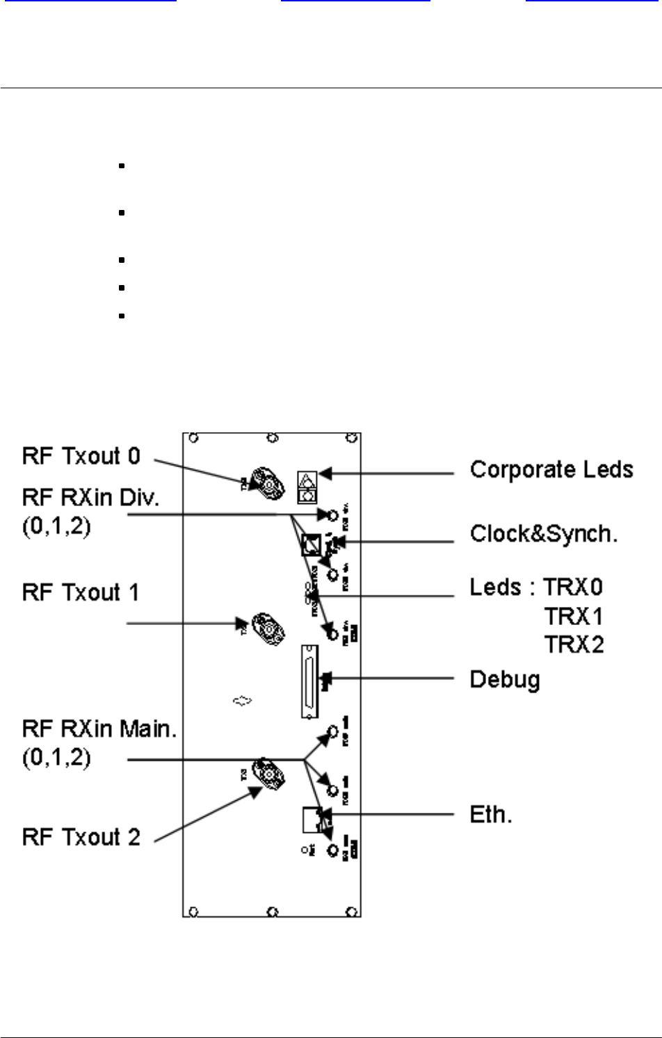
The RM includes the following elements:
a Power Supply Unit (PSU) delivering, from the 24/48V main power supply, the
secondary supplies (27V, 3.3V, 5.7V) to the other blocks of the RM,
the RF RX board (RM RX), three dual narrowband receiver chains (main and
diversity),
the RF TX board (RM TX), three low level transmit drivers,
the RF PA board (RM PA), three Power Amplifier (PA) lines up,
the Logic Radio Module (LRM), the digital control board.
3.2.2.2 Front panel
Figure 3--3 RM front panel
BTS18000 hardware
Front page of manual Welcome screenUser’s help screen
Nortel Networks Confidential 3--9
BTS18000 Reference Manual
Copyright E2002--2004 Nortel Networks
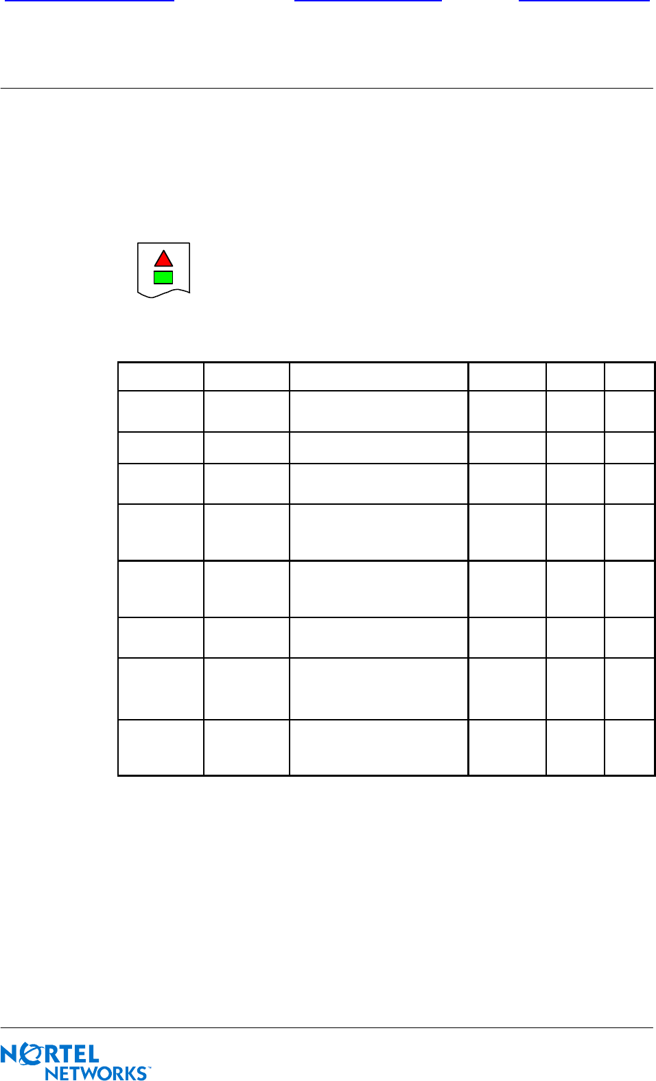
3.2.2.3 BTS18000 corporate LEDs behavior
As shown on Figure 3--4, an upper triangle--shaped red LED and a lower
rectangle--shaped green LED are used to indicate the status for the RM, as well as
for the ICM and ABM modules. See Table 3--3 for detailed status information.
Figure 3--4 BTS18000 corporate LEDs for RM, ICM and ABM
Green LED Red LED Module status ICM RM ABM
switched off switched off un--powered or not inserted
(default hardware value) used used used
JYstarting, BISTs in progress used used used
Jswitched off module OK (should not be
removed) used used used
Jblinking
module is possibly partially
faulty
ICM
installation
problem
TRX(s)
in fault
not
used
switched off Yalarm status: module NOK,
must be removed and
replaced
used RM is
in fault used
switched off blinking module is being indicated not used not
used
not
used
blinking
Y
or
switched off
wait for ICM connection used on
passive
ICM
used used
blinking blinking
internal downloading used on
passive
ICM
not
used used
Table 3--3 BTS18000 corporate LEDs behavior (RM, ICM, ABM)
BTS18000 hardware
Front page of manual Welcome screenUser’s help screen
Nortel Networks Confidential
3--10
PE/DCL/DD/0160
411--9001--160
Preliminary 15.01/EN October 2004 Copyright E2002--2004 Nortel Networks
3.2.2.4 Ethernet LEDs behavior
The TX (green) and LI (amber) Ethernet LEDs are on the Ethernet connector. See
Table 3--3 for color explanations.
LED
Name
Color Meaning
LI FEthernet link, switched on when connection is established
TX FTX Ethernet, switched on during data transfer
Table 3--4 RM Ethernet LEDs behavior
3.2.2.5 TRX LEDs behavior
Table 3--5 describes the TRX LEDs behavior.
LED
Name
Color Meaning
TRX
0--1--2
Amber -- flashes during SPU cluster download
-- blinks until BSC connection, including Abis downloading
-- switched off when TRX is operational
Table3--5 RMTRX0--1--2LEDsbehavior
3.2.2.6 LEDs behavior at RM starting up
Table 3--6 describes the LEDs behavior at RM starting up.
RM
power
up
RM
start
up
RM
BISTs
RM
soft
start
RM soft
init
(1/2)
SPU
load &
start
RM soft
init
(2/2)
Connection
to BCF/Abis
downloading
Nominal
operation
triangle
corporate Y Y Y Y
rectangle
corporate J J J J J
blinking
J
blinking
J
blinking J J
TRX
0--1--2 amber amber amber
blinking amber blinking
Table 3--6 LEDs behavior at RM starting up

BTS18000 hardware
Front page of manual Welcome screenUser’s help screen
Nortel Networks Confidential 3--11
BTS18000 Reference Manual
Copyright E2002--2004 Nortel Networks
3.2.3 High Power Radio Module (HPRM)
The HPRM is a variant of the RM with only a two--TDMA capacity. This variant
shares with the RM the following elements:
the PSU,
the LRM,
the RM TX,
the RM RX.
The BTS18000 with HPRM is only available in GSM900 frequency band.
The HPRM can operate on:
one--sector basis (two carriers per sector, O2 mode),
two--sector basis (one carrier per sector, S11 mode).
Maximum configurations for BTS18000 mono--cabinet with HPRM are S444, O12
and S66.
3.2.4 Interface Control Module (ICM)
3.2.4.1 Function
The ICM is only used in the BTS18000 base cabinet. It is not present in the extension
cabinets. It is designed to manage the whole BTS18000 site in simplex
configuration.
The ICM in simplex mode covers the functions related to a complete site including:
support of drop--and--insert facilities for the PCM links with the BSC,
reference clock for the air interface, synchronized on the Abis PCM interface, a
synchronizing BTS or a GPS antenna,
GSM_TIME calculations with possible network synchronization,
switching of PCM slots,
conversion of electrical signals, from external to internal PCM data formats,
concentration of the data flow of the BTS,
configuration and supervision of all the modules.
The ICM is composed of a single board with connections on the IBP and on the front
panel.
BTS18000 hardware
Front page of manual Welcome screenUser’s help screen
Nortel Networks Confidential
3--12
PE/DCL/DD/0160
411--9001--160
Preliminary 15.01/EN October 2004 Copyright E2002--2004 Nortel Networks
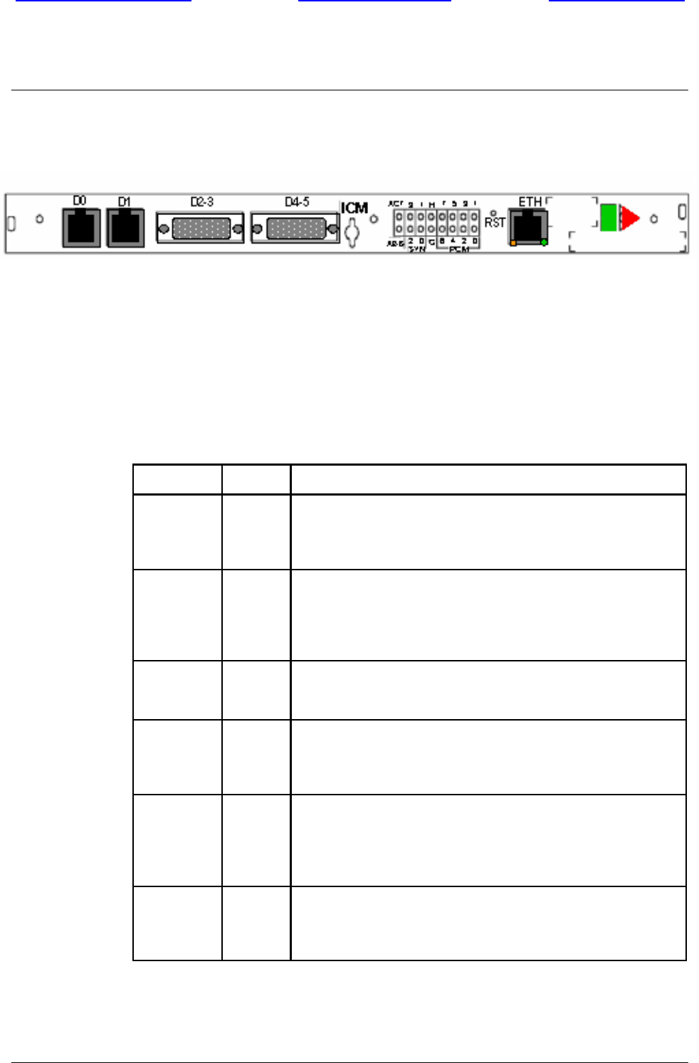
3.2.4.2 Front panel
Figure 3--5 ICM front panel
3.2.4.3 LEDs behavior
For detailed information on the BTS18000 corporate LEDs behavior, refer to
Section 3.2.2.3.Table 3--7 gives detailed information on ICM LEDs behavior. All
the LEDs are OFF when the ICM is un--powered. All the LEDs are amber during
BISTs.
LED name Color Meaning
PCMx
(x = 0 to 7) F
F
F
8 PCM status LEDs (one per PCM):
-- Green: the PCM is OK
-- Red: the PCM is in fault
-- Amber: the PCM is in test
G
(GPS)
F
F
F
1 GPS or external synchro status LED:
-- OFF: no external synchronization
-- Green: GPS synchronization
-- Red: bad external synchronization signal
-- Amber: master BTS synchronization
SYN
(synchro)
FFour LEDs for synchronizing source: one out of the 8 PCMs
or external synchronization (in that case the 4 LEDs are ON)
-- see Table 3--8 --
H
(holdover)
FOne LED for synchro locked status:
-- ON on active ICM: un--locked or holdover indication
-- ON on passive ICM: un--locked indication
-- OFF: synchro is locked on external source
ACT
(activity) F
F
One LED for ICM Passive or Active Status:
-- Green: the ICM is active
-- OFF: the ICM is passive
-- Red on both ICMs: the simplex or duplex configuration
cannot be determined, both ICMs are in faulty passive state
ABIS FLevel--2 status with BSC:
-- ON: level--2 is OK
-- Blinking: downloading in progress
-- OFF: no Level--2 with the BSC
Table 3--7 ICM LEDs behavior
BTS18000 hardware
Front page of manual Welcome screenUser’s help screen
Nortel Networks Confidential 3--13
BTS18000 Reference Manual
Copyright E2002--2004 Nortel Networks
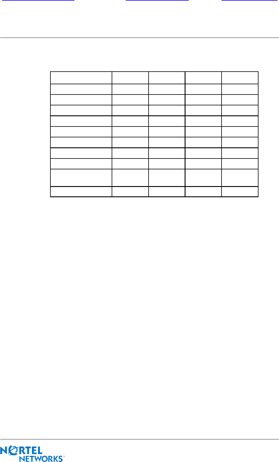
The behavior of the four LEDs for synchronization source is described in Table 3--8.
SYNCHRO SOURCE 0 1 2 3
PCM 0 Fswitched off switched off switched off
PCM 1 switched off Fswitched off switched off
PCM 2 F F switched off switched off
PCM 3 switched off switched off Fswitched off
PCM 4 Fswitched off Fswitched off
PCM 5 switched off F F switched off
PCM 6 F F F switched off
PCM 7 switched off switched off switched off F
external source
(GPS, master BTS) F F F F
holdover switched off switched off switched off switched off
Table 3--8 ICM SYN LEDs behavior
3.2.4.4 LEDs behavior at active ICM starting up
The LEDs behavior, when the active ICM starts up, is as follows:
1When the BTS18000 is turned on, H (holdover) and ACT (active) LEDs
switch ON.
2After the Built--in Self Test (BIST) sequence, the ICM searches for
synchronizing with the PCM0 link.
3When the clock source is found, H LED switches OFF and synchro source
LEDs (SYN) switch ON (see Table 3--8).
Table 3--9 describes the LEDs behavior at active ICM starting up.
BTS18000 hardware
Front page of manual Welcome screenUser’s help screen
Nortel Networks Confidential
3--14
PE/DCL/DD/0160
411--9001--160
Preliminary 15.01/EN October 2004 Copyright E2002--2004 Nortel Networks
ICM boot
sequence ICM BISTs Abis
connection
ICM
downloading
Nominal
operation
triangle
corporate Y Y
rectangle
corporate J J J J J
ACT FF F F
SYN FF F F
GF
Abis FF F blinking F
PCMx FF F F
HFF
Table 3--9 LEDs behavior at active ICM starting up
3.2.4.5 LEDs behavior at passive ICM starting up
The passive ICM can be differentiated from the active one thanks to the ACT LED
switched off. The behavior of the SYN and PCM LEDs is the same as for the active
ICM.
Table 3--10 describes the LEDs behavior at passive ICM starting up.
ICM boot
sequence ICM BISTs Active ICM
connection
Passive ICM
downloading
Nominal
operation
triangle
corporate Y Y Yor
switched off Yblinking
rectangle
corporate J J J blinking Jblinking J
ACT F
SYN FF F F
GF
Abis F
PCMx FF F F
HFF
Table 3--10 LEDs behavior at passive ICM starting up
BTS18000 hardware
Front page of manual Welcome screenUser’s help screen
Nortel Networks Confidential 3--15
BTS18000 Reference Manual
Copyright E2002--2004 Nortel Networks
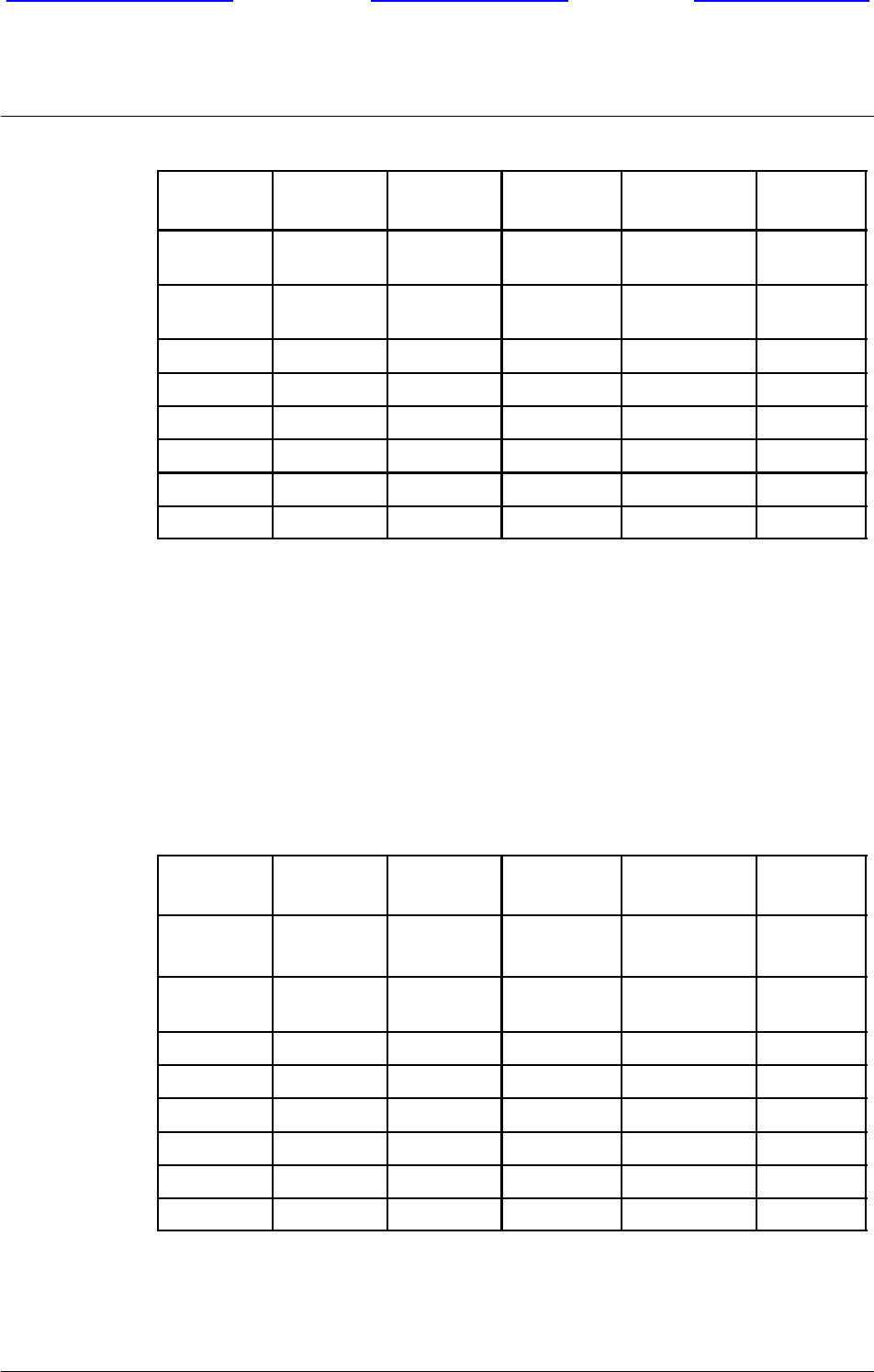
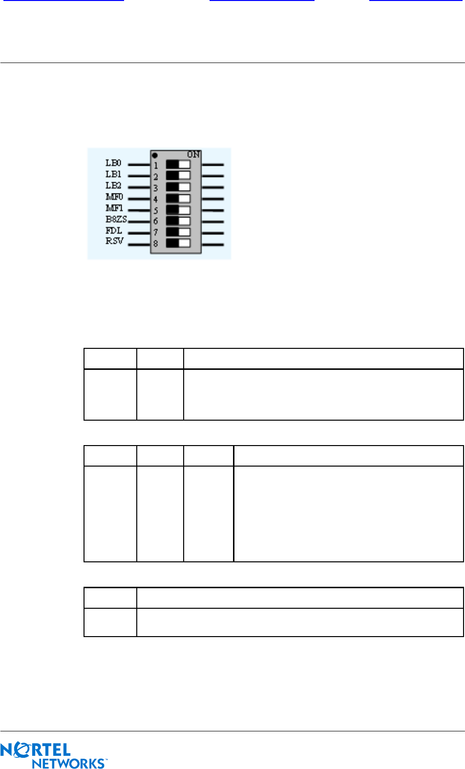
3.2.4.6 Configuration of the ICM switches for commissioning
SW0--SW7 switches: one per Abis line
Figure 3--6 ICM Abis switch
The E1 or T1 mode selection is performed thanks to switch SW10 (see Table 3--13).
Refer to Table 3--11 and Table 3--12 for detailed information on E1/T1
configurations of the ICM Abis switches.
MF1 MF0 Frame Format
OFF
OFF
ON
ON
OFF
ON
OFF
ON
12--frame multi--frame (Super--Frame)
Extended Super--frame (ESF) with CRC6 check/generation
Extended Super--frame (ESF) without CRC6 check/generation
Not used
LB2 LB1 LB0 Line Build--Out
OFF
OFF
OFF
OFF
ON
ON
ON
ON
OFF
OFF
ON
ON
OFF
OFF
ON
ON
OFF
ON
OFF
ON
OFF
ON
OFF
ON
length = 000..133ft (0.6dB -- DSX--1) / 0.0dB (DS1)
length = 133..266ft (1.2dB -- DSX--1)
length = 266..399ft (1.8dB -- DSX--1)
length = 399..533ft (2.4dB -- DSX--1)
length = 533..655ft (3.0dB -- DSX--1)
--7.5dB (DS1)
--15.0dB (DS1)
--22.5dB (DS1)
B8ZS Line code
OFF
ON
AMI coding
B8ZS coding
Table 3--11 ICM Abis switch -- T1 configuration
BTS18000 hardware
Front page of manual Welcome screenUser’s help screen
Nortel Networks Confidential
3--16
PE/DCL/DD/0160
411--9001--160
Preliminary 15.01/EN October 2004 Copyright E2002--2004 Nortel Networks
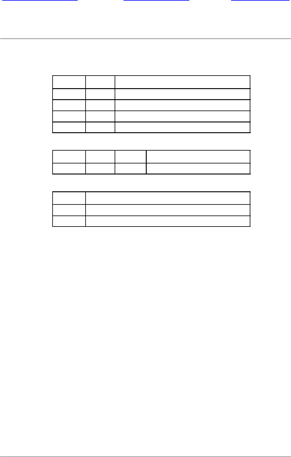
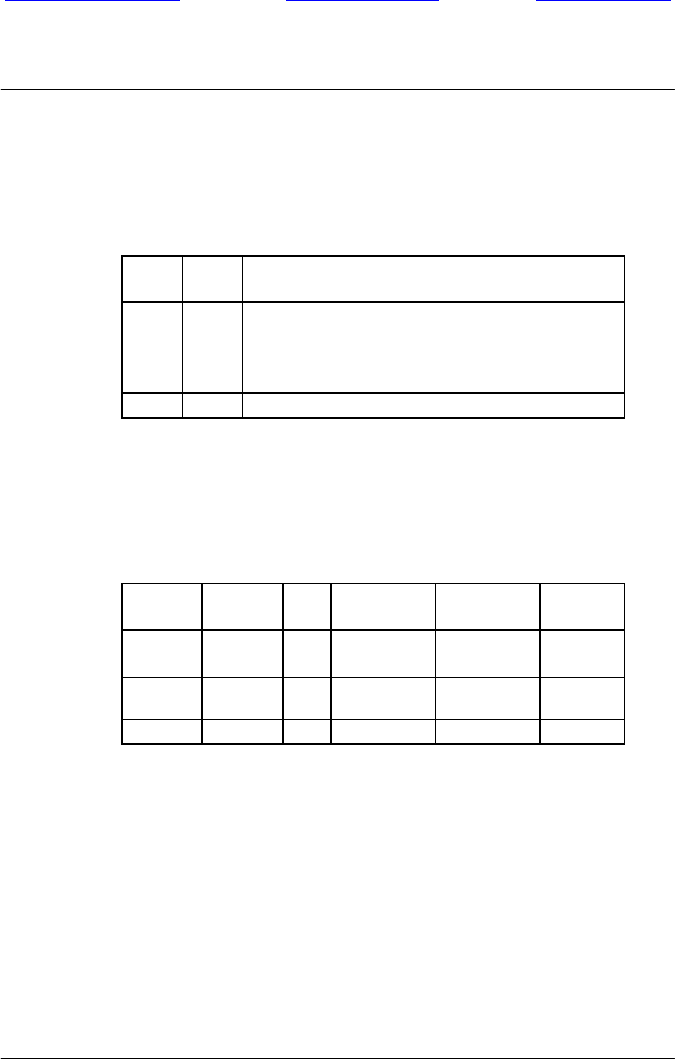
FDL (Facility Data--Link) and RSV are not used. Their default value is OFF.
MF1 MF0 Frame Format
OFF OFF Single frame
OFF ON Multi--frame with CRC4 decoding
ON OFF Multi--frame without any CRC4 decoding
ON ON Automatic multi--frame with CRC4 decoding
LB2 LB1 LB0 Line Build--Out is NOT used
OFF OFF OFF Default value
B8ZS Line code
OFF HDB3 coding
ON AMI coding (provision)
Table 3--12 ICM Abis switch -- E1 configuration
FDL (Facility Data--Link) and RSV are not used. Their default value is OFF.
BTS18000 hardware
Front page of manual Welcome screenUser’s help screen
Nortel Networks Confidential 3--17
BTS18000 Reference Manual
Copyright E2002--2004 Nortel Networks
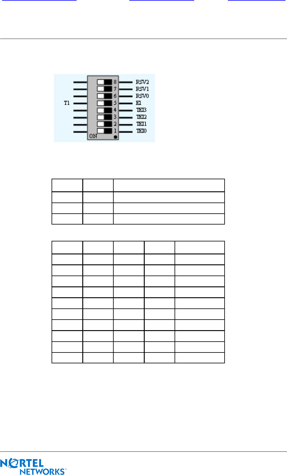
SW10 switch
Figure 3--7 ICM SW10 switch
E1/T1 RSV0 Frame Format
OFF OFF E1 mode (120 ohms)
OFF ON E1 mode with 75 ohms adapter
ON -- T1 mode (100 ohms)
TEI(3) TEI(2) TEI(1) TEI(0) Site TEI coding
OFF OFF OFF OFF 0
OFF OFF OFF ON 1
OFF OFF ON OFF 2
OFF OFF ON ON 3
OFF ON OFF OFF 4
OFF ON OFF ON 5
OFF ON ON OFF 6
OFF ON ON ON 7
ON OFF OFF OFF 8
ON OFF OFF ON 9
Table 3--13 ICM SW10 switch configuration
An ICM board cannot start if its TEI value is out of the range given in Table 3--13.
Factory setting is TEI equal to zero. RSV(0--2) are unused (default value is OFF).
BTS18000 hardware
Front page of manual Welcome screenUser’s help screen
Nortel Networks Confidential
3--18
PE/DCL/DD/0160
411--9001--160
Preliminary 15.01/EN October 2004 Copyright E2002--2004 Nortel Networks
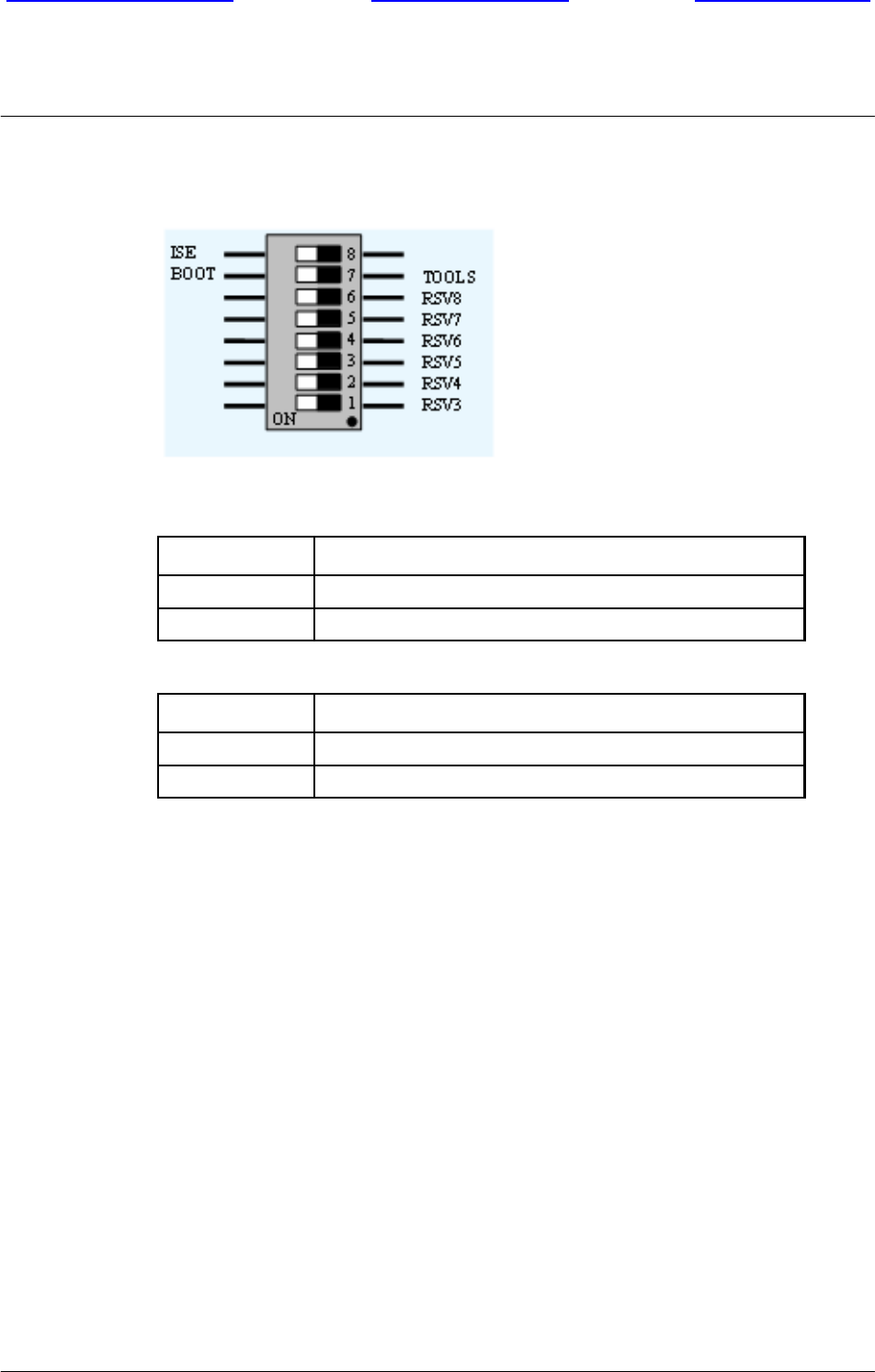
SW11 switch
Figure 3--8 ICM SW11 switch
ISE ICM for New--SEB mode
OFF ICM in nominal mode
ON ICM in New--SEB mode if confirmation bit is set in FPGA
BOOT/TOOLS Processor booting mode
OFF Require emulator probe connected
ON Booting in Flash memory (nominal mode)
Table 3--14 ICM SW11 switch configuration
RSV(3--8) are unused (default value is OFF). Passive and active ICM must have the
same switches configuration. Otherwise, both ICM are in the ”passive partially
faulty” state: the corporate green LED is ON and the red one is blinking.

BTS18000 hardware
Front page of manual Welcome screenUser’s help screen
Nortel Networks Confidential 3--19
BTS18000 Reference Manual
Copyright E2002--2004 Nortel Networks
3.2.5 Interface Module (IFM)
The IFM is only used in the BTS18000 base cabinet. It is not present in the extension
cabinets. Its main function is to provide connectivity and secondary protection on
the PCM links.
It provides the following access for the ICM:
E1 (120 ohms) or T1 (100 ohms) connectivity on the Abis link with secondary
protection and filters (four PCM per IFM),
connectivity for an external synchronization source (synchronizing BTS or GPS
antenna),
connectivity for Abis extension and redundant ICM options.
The IFM is a passive board.
3.2.6 Spare Module (SPM)
The SPM is reserved for future use in the BTS18000 base cabinet only. It is not
present in the extension cabinets. The SPM is designed to add extra features to the
ICM without replacing the ICM hardware.
3.2.7 Alarms and Bridge Module (ABM)
One ABM is used in each BTS18000 digital rack. Therefore, a BTS18000 cabinet
contains two ABMs (even and odd).
The ABM is composed of a single board with connections on the DBP and on the
front panel.
3.2.7.1 Alarm collector function
The ABM alarm collector function performs the following operations under the
ICM control:
Detection of cabinet alarms:
xdoor status,
xoutdoor cabinet User Rack and ADU.
Presence detection of the digital rack, combiner rack and other cabinet modules:
xdigital rack modules: IFM, ICM, SPM and the three RMs,
xRF combiners: DDM, TX filter (TXF), DDM (H2) and TXF (H2),
xcabinet modules: indoor SICS, outdoor ECU and UCPS.

BTS18000 hardware
Front page of manual Welcome screenUser’s help screen
Nortel Networks Confidential
3--20
PE/DCL/DD/0160
411--9001--160
Preliminary 15.01/EN October 2004 Copyright E2002--2004 Nortel Networks
Inventory of the digital rack, combiner rack and other cabinet modules:
xIFM, ICM, SPM and the three RMs, via the I2C bus,
xDDM, TXF, DDM (H2) and TXF (H2), via the pseudo I2C over RS422,
xindoor SICS and outdoor ECU,
xUCPS modules, through a dedicated protocol over RS422.
Alarm polling of the radio coupling modules, through the pseudo I2C bus over
RS422:
xLow Noise Amplifier (LNA) over--current detection in the DDMs,
xVSWR alarms and associated setting of thresholds in the DDMsand TX filters
with the VSWR option.
Alarm polling of the cooling system modules, through the pseudo I2C bus over
RS422:
xindoor SICS blowers, filter, power and control board status,
xoutdoor ECU blowers, filter, damper, heater, power and control board status.
Alarm polling of the outdoor cabinet UCPS:
xAC monitoring,
xDC monitoring,
xbreakers status,
xbattery status.
Software management of the outdoor cabinet UCPS, through a dedicated
protocol over RS422:
xupdating of the UCPS software release,
xsetting up of certain parameters inside the UCPS in order to fit its
configuration to the BTS18000 cabinet and battery type,
xcontrolling the UCPS.
Optional external alarm detection (up to eight customer alarms per ABM).
Remote control drive (up to two remote controls per ABM).
3.2.7.2 Bridge function
The ABM assures bridge functions between several interfaces:
On one side, it manages interface with ICM (one front panel D link or two in case
of ICM redundancy),
On the other side, the bridge manages one internal E link for ABM alarm function
and three E links to the RM modules.
BTS18000 hardware
Front page of manual Welcome screenUser’s help screen
Nortel Networks Confidential 3--21
BTS18000 Reference Manual
Copyright E2002--2004 Nortel Networks
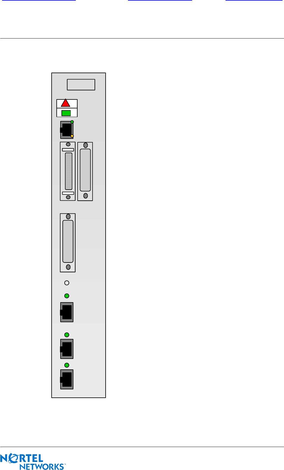
3.2.7.3 Front panel
D
ETH
RI
C
O
&
D
D
UAR
T
DALI
Rst
Figure 3--9 ABM front panel
BTS18000 hardware
Front page of manual Welcome screenUser’s help screen
Nortel Networks Confidential
3--22
PE/DCL/DD/0160
411--9001--160
Preliminary 15.01/EN October 2004 Copyright E2002--2004 Nortel Networks
3.2.7.4 ABM LEDs behavior
For detailed information on the BTS18000 corporate LEDs behavior, refer to
section 3.2.2.3.
Table 3--15 describes the ABM LEDs behavior.
LED
Name Color Meaning
DF2 LEDs for D activity
ON: when the connection to active ICM through the D
link related to the LED is correctly established
Only one of the 2 D LEDs can be ON
UART FON: UART activity (reserved for future use)
Table 3--15 ABM LEDs behavior
3.2.7.5 LEDs behavior at ABM starting up
Table 3--16 describes the LEDs behavior at ABM starting up.
ABM boot
sequence
ABM
BIST
Active ICM
connection
ABM
downloading
Nominal
operation
triangle
corporate Y Y Yor
switched off Yblinking
rectangle
corporate J J J blinking Jblinking J
DF F F
Table 3--16 LEDs behavior at ABM starting up
Note: External alarms do not impact the ABM corporate LEDs management
(these LEDs only indicate ABM board alarms).
BTS18000 hardware
Front page of manual Welcome screenUser’s help screen
Nortel Networks Confidential 3--23
BTS18000 Reference Manual
Copyright E2002--2004 Nortel Networks
3.2.8 Dual Duplexer Module (DDM) and Transmit Filter (TXF)
The operator can use different types of couplers to couple the PAs to the antennas
and to combine the RX and TX paths:
duplexers,
transmit filters,
hybrid combiners.
These couplers can be found in the following BTS18000 modules:
DDM or DDM with optional H2 coupling, both including an optional VSWR
meter,
TXF or TXF with optional H2 coupling, both including an optional VSWR
meter.
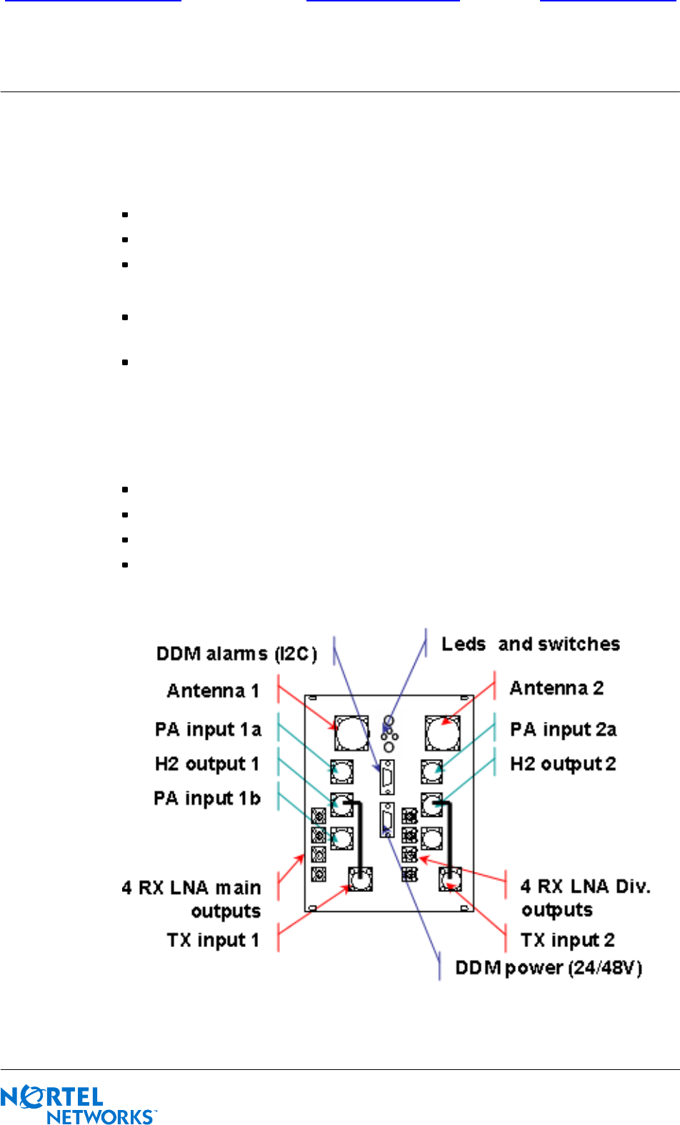
3.2.8.1 Dual Duplexer Module (DDM)
The DDM allows to share TX and RX signals on a same antenna. The DDM is aimed
at providing:
TX filtering (noise suppression),
RX filtering (noise suppression),
TX to RX isolation,
front end low noise amplification for the receive chain.
Front panel
Figure 3--10 DDM front panel (with H2 coupling option)
BTS18000 hardware
Front page of manual Welcome screenUser’s help screen
Nortel Networks Confidential
3--24
PE/DCL/DD/0160
411--9001--160
Preliminary 15.01/EN October 2004 Copyright E2002--2004 Nortel Networks
DDM LEDs description
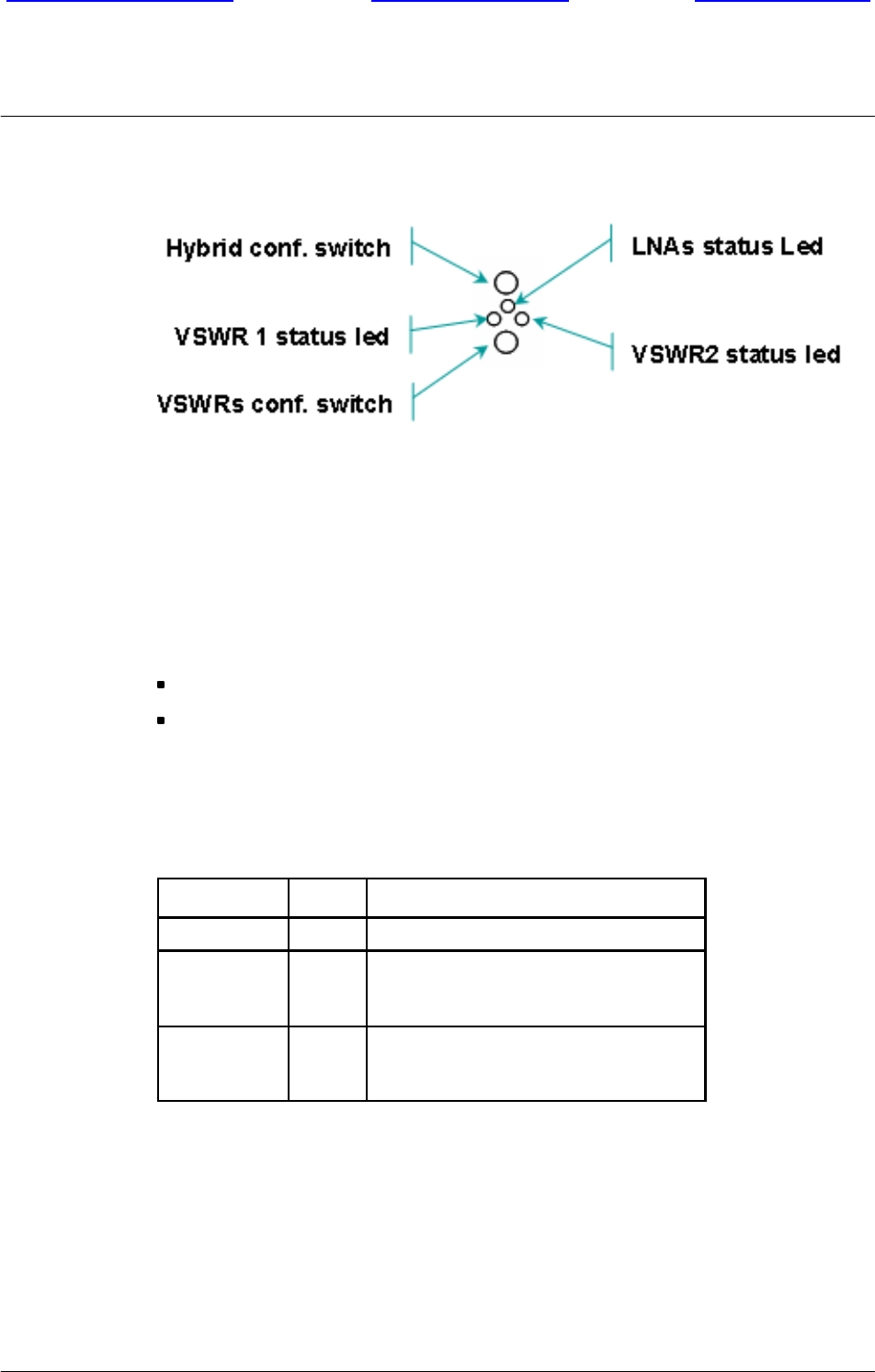
Figure 3--11 DDM LEDs and switches details
DDM LEDs behavior
Three LEDs are located on the DDM font panel in order to monitor DDM internal
alarm:
one LED is dedicated to LNAs high/low consumption alarm,
two LEDs are dedicated to VSWR meter:
xone for antenna 1 port,
xone for antenna 2 port.
Table 3--17 describes the DDM LEDs behavior.
LED Name Color Meaning
LNA FON when LNA is enabled
VSWR1
F
F
Red: Port 1 VSWR alarm level 3
Amber: Port 1 VSWR alarm level 2
OFF: no alarm or level 1
VSWR2
F
F
Red: Port 2 VSWR alarm level 3
Amber: Port 2 VSWR alarm level 2
OFF: no alarm or level 1
Table 3--17 DDM LEDs behavior

BTS18000 hardware
Front page of manual Welcome screenUser’s help screen
Nortel Networks Confidential 3--25
BTS18000 Reference Manual
Copyright E2002--2004 Nortel Networks
Configuration of the DDM switches for commissioning
Two four--position rotate switches are located on the DDM front panel (see
Figure 3--11).
These switches must be positioned on site:
The hybrid configuration switch is used to inform the system about the use of the
two 2--way hybrid (by--passed or not).
Table 3--18 gives the switch position meaning.
Hybrid configuration switch Switch position
DDM with two hybrids 0
DDM with hybrid 1 connected 1
DDM with hybrid 2 connected 2
DDM without hybrid 3
Table 3--18 DDM switches configuration
The VSWR switch allows modifying, on site, the VSWR meter thresholds on
both antenna ports. The three first positions (positions 0, 1 and 2) are used to
offset VSWR thresholds of respectively 0, 2 or 4 dB.
The fourth position (test position) checks that the three LEDs operate correctly.
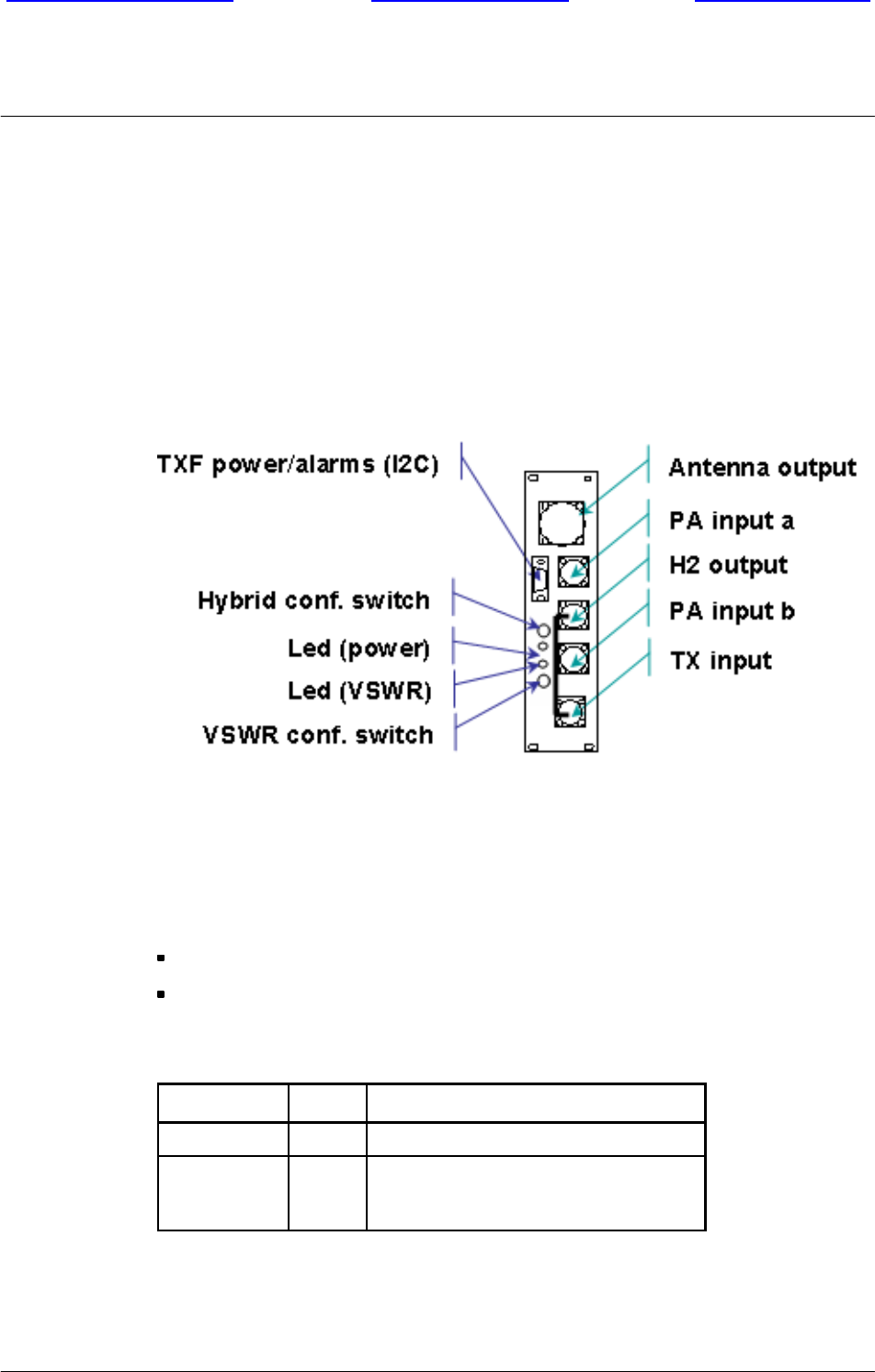
BTS18000 hardware
Front page of manual Welcome screenUser’s help screen
Nortel Networks Confidential
3--26
PE/DCL/DD/0160
411--9001--160
Preliminary 15.01/EN October 2004 Copyright E2002--2004 Nortel Networks
3.2.8.2 Transmit Filter (TXF)
The TXF is used, as a complement of the DDM, each time extra transmit capacity
is required without need of receive capacity. It allows direct connection from the
RM PA output to the antenna.
The TXF only filters the signal transmitted from the PA to the antenna and does not
provide the reception path.
Front panel
Figure 3--12 TXF front panel (with H2 coupling option)
TXF LEDs behavior
Two LEDs are located on the TXF font panel in order to monitor TXF alarm:
one LED is dedicated to DC power status,
one LED is dedicated to VSWR meter.
Table 3--19 describes the TXF LEDs behavior.
LED Name Color Meaning
Power FON when TX filter is powered on
VSWR
F
F
Red: VSWR alarm level 3
Amber: VSWR alarm level 2
OFF: no alarm or level 1
Table 3--19 TXF LEDs behavior
BTS18000 hardware
Front page of manual Welcome screenUser’s help screen
Nortel Networks Confidential 3--27
BTS18000 Reference Manual
Copyright E2002--2004 Nortel Networks
Configuration of the TXF switches for commissioning
Two switches are located on the TXF front panel (see Figure 3--12). These switches
must be positioned on site:
The hybrid configuration two--position switch is used to inform the system about
the use of the hybrid (by--passed or not).
Table 3--20 gives the switch position meaning.
Hybrid configuration switch Switch position
TXF with hybrid 0
TXF without hybrid 1
Table 3--20 TXF switches configuration
The VSWR four--position switch allows modifying, on site, the VSWR meter
thresholds on both antenna ports. The three first positions (positions 0, 1 and 2)
are used to offset VSWR thresholds of respectively 0, 2 or 4 dB.
The fourth position (test position) checks that the two LEDs operate correctly.

BTS18000 hardware
Front page of manual Welcome screenUser’s help screen
Nortel Networks Confidential
3--28
PE/DCL/DD/0160
411--9001--160
Preliminary 15.01/EN October 2004 Copyright E2002--2004 Nortel Networks
PAGE INTENTIONALLY LEFT BLANK