Avaya Canada NT1900FRM CDMA Metrocell BTS User Manual 1900 User mif
Avaya Canada Corporation CDMA Metrocell BTS 1900 User mif
UserManual.wiki
>
Avaya Canada
>
NT1900FRM User Manual
Document with the title Outdoor Cell Site Requirements
Navigation menu
Upload a User Manual
Namespaces
Wiki Guide
HTML
PDF
Info
Views
User Manual
Discussion / Help
Navigation
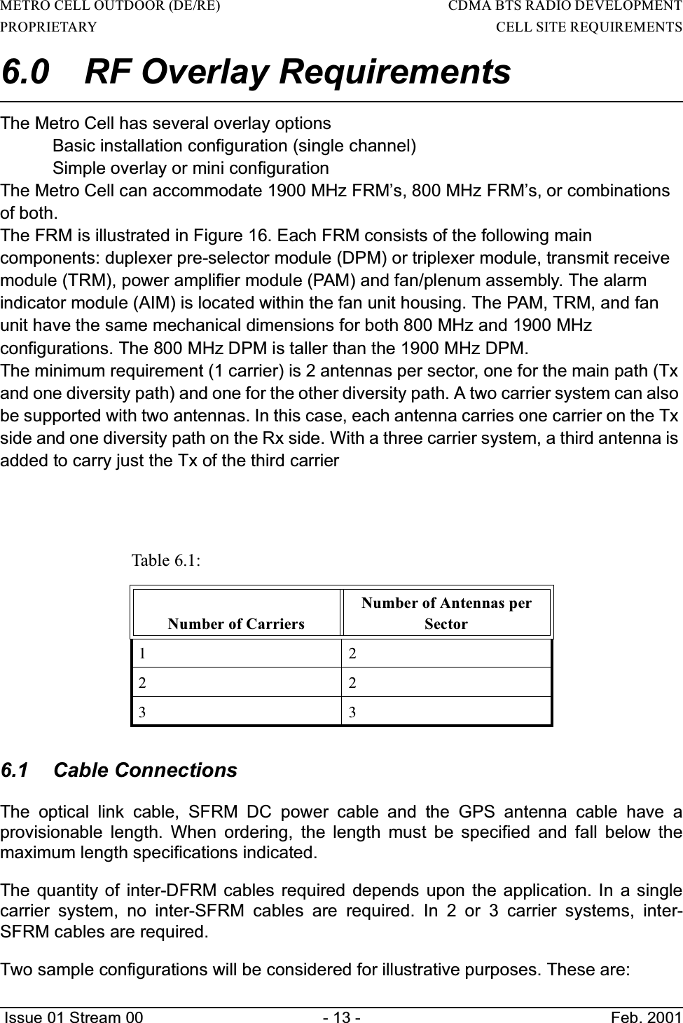
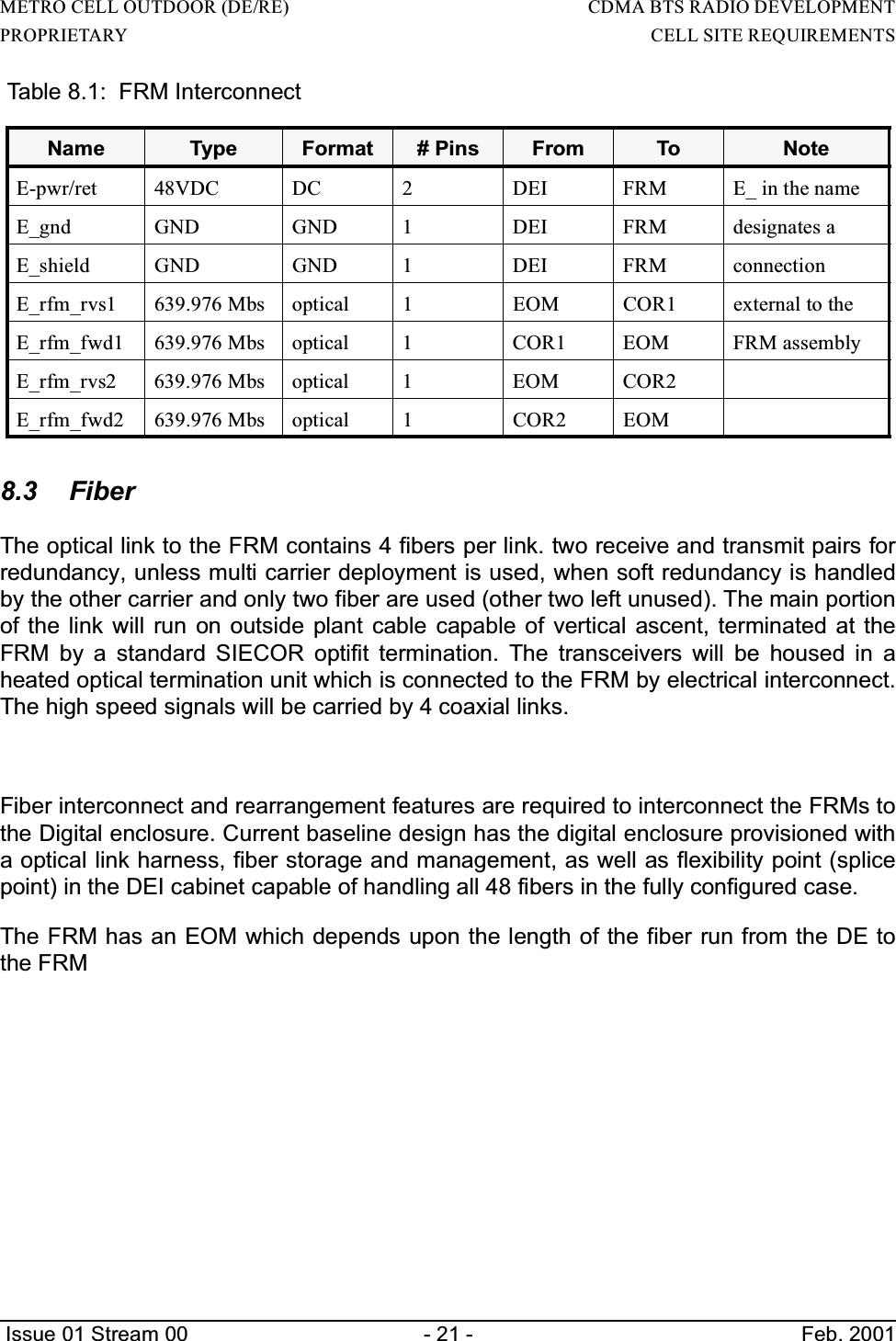
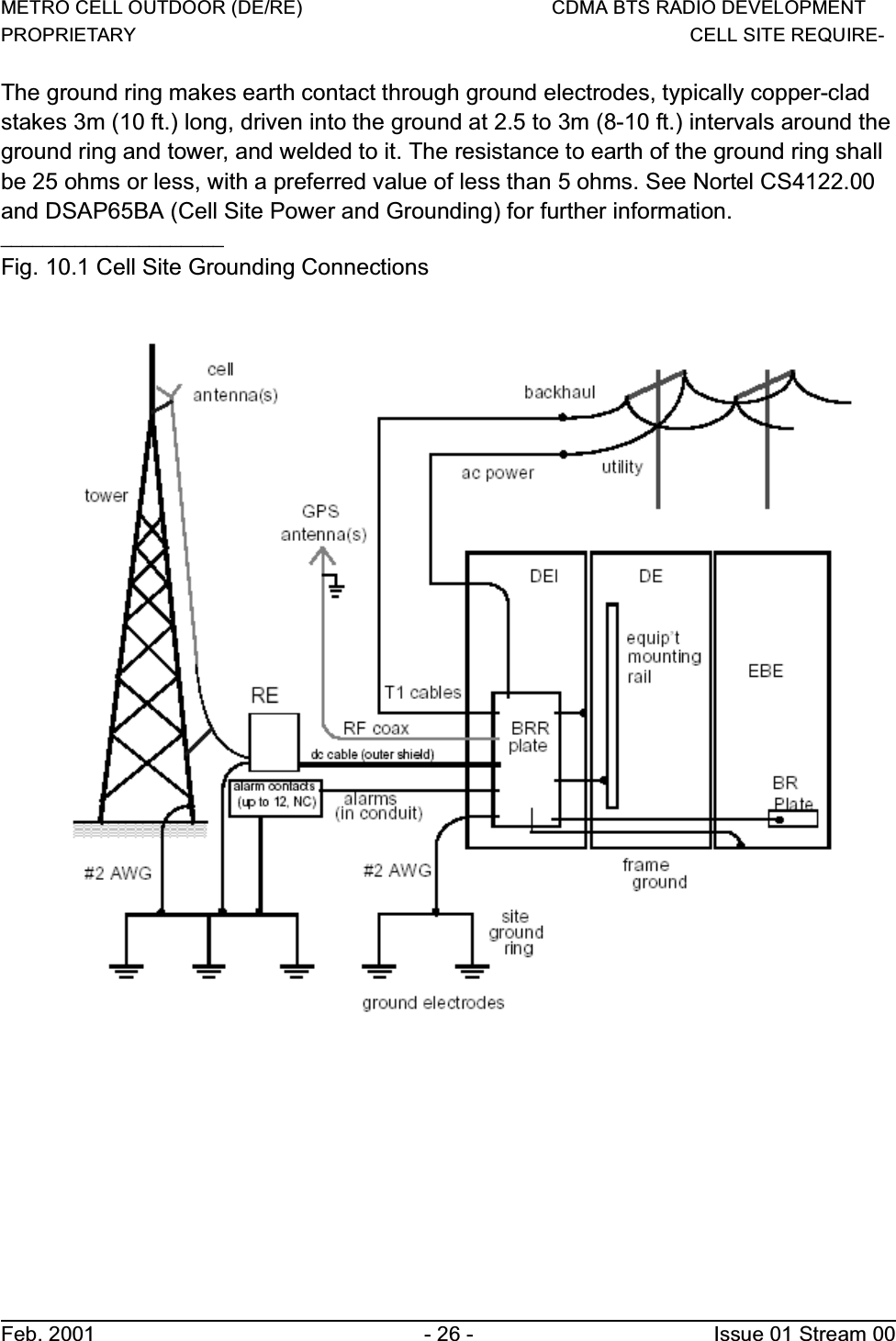
![METRO CELL OUTDOOR (DE/RE) CDMA BTS RADIO DEVELOPMENTPROPRIETARY CELL SITE REQUIRE-Feb. 2001 - 22 - Issue 01 Stream 009.0 T1/E1 ConnectionsThe CM module has up to 6T1 interfaces connected through the backplane. The cablewill probably be lumped in two 12 wire bundles terminated at the digital shelf backplaneby two 15 pin dsubs.The Metro Cell can be connected to the BSC using 1 to 6 T1/E1 links. These T1/E1links are distributed between the two DCGs i.e. if one DCG has 4 T1/E1s connected to itthen the other can have a maximum of two T1/E1 links. All T1/E1s connected to eachDCG need to have the same timing reference at the BSC. Each link requires 2 twistedpairs.There are two ways of connecting T1/E1 to the Metro Cell. The T1/E1 cables can bedirectly brought into the DEI or they can be connected to a RJ48H connector whichinterfaces with the DEI. The RJ48H connector cable NTGS0106 is provisionable. In theDEI T1/E1 connections are done on the middle and lower blocks among the threeTelephone/Data Line Protection blocks as shown in Figure 87. The RJ48H connector isshown in Figure 88 and the pinout is shown in Table 30.The number of T1/E1s that need to be connected to the Metro Cell depends on the callcarrying capacity of the T1/E1s and the number of calls that a Metro Cell has to make.The number of T1/E1 that need to be provisioned for a Metro Cell can be determinedfrom Ref [10].The two modes of operation of Metro Cell are regular (or non-split) mode or split mode.In the regular mode only one DCG is active, the other DCG may not be provisioned or isa redundant DCG. In the split mode both DCGs are provisioned and are active. EachDCG in the split mode is a logical BTS. The T1/E1 connections of the Metro Cell in theregular and split mode are done as shown in Table 27.The T1/E1 lines are connected to one of the two BTSI cards in the control module (CM)](https://usermanual.wiki/Avaya-Canada/NT1900FRM/User-Guide-245853-Page-23.png)
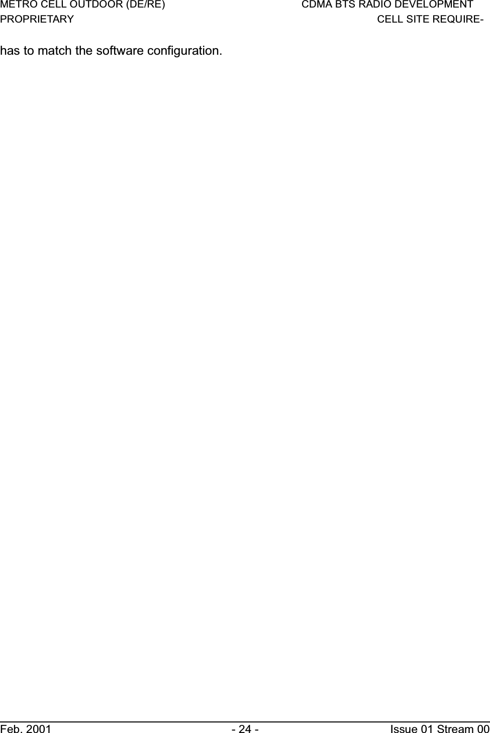
![METRO CELL OUTDOOR (DE/RE) CDMA BTS RADIO DEVELOPMENTPROPRIETARY CELL SITE REQUIREMENTS Issue 01 Stream 00 - 23 - Feb. 2001Table 27: T1/E1 Connections of Metro Cell without Daisy ChainingThe T1/E1 lines are connected to one of the two BTSI cards in the control module (CM)which forms part of the DCG. The connections are controlled by relays and are exclusiveto one DCG. Therefore if T1/E1 #1 is connected to the first DCG then the same linescannot be connected to the other DCG. This is true in regular as well as split mode. Inregular mode since only one DCG is active, therefore, all the T1/E1s are connected tothe active DCG. When the redundant DCG takes over then the connections are switchedto it by closing the relays on this new active DCG and opening them on the previouslyactive DCG. The middle column of Table 27 shows how the T1/E1 connections are donefor the active DCG in regular mode. In the split mode each DCG is active and is part ofthe logical BTS. Therefore, each DCG has its own independent T1/E1 connections. Theright column of Table 27 shows how the T1/E1 connections are done for the two logicalBTSs in the split mode. It is clear from [1] that a single DCG, supporting a maximum oftwo carriers, does not need more than 3 T1/E1 connections. So, the connections shownin Table are reasonable and will provide for a redundant T1/E1 link per logical BTS inmost cases (keeping in mind the number of T1/E1 links needed for 2 carriers asmentioned in [10]).The Metro Cell can be configured for a shorthaul link or a longhaul link. In case of ashorthaul configuration the Metro Cell should be within 655ft of the last repeater while fora longhaul link the Metro Cell should be within 6000ft of the last repeater using 22 gaugeunshielded twisted pair cable i.e. 100 ohm 22 gauge cable. The shorthaul and longhaullink is configured using software. The distance of the Metro Cell from the last repeater-](https://usermanual.wiki/Avaya-Canada/NT1900FRM/User-Guide-245853-Page-24.png)
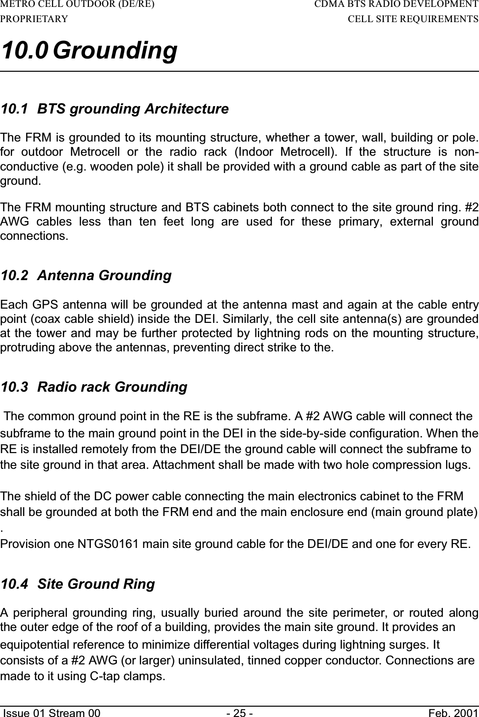
![METRO CELL OUTDOOR (DE/RE) CDMA BTS RADIO DEVELOPMENTPROPRIETARY CELL SITE REQUIREMENTS Issue 01 Stream 00 - 27 - Feb. 200111.0 References [1] CMS-MTX/CDMA MCBTS 1900 Outdoor and MCBTS Base Platform. ProductSpecification Agreement. by Neil McGowan and Frank van Heeswyk.[2] CDMA MCBTS 1900 Outdoor. Power Protection and Grounding Design Specification.by Ed Norman.[3] CDMA MCBTS 1900 Outdoor. General Specification.[4] MCBTS 1900 MHz Radio Enclosure System Packaging Specification. by Fred Folk.[5] MCBTS Optical Link NTGS05AA, NTGS0117, NTGS0095 Functional Agreement.Packaging Concepts Methodology.[6] MCBTS Digital Enclosure Mechanical Assembly NTGS13AA Functional Agreement.Packaging Concepts Methodology._____________________](https://usermanual.wiki/Avaya-Canada/NT1900FRM/User-Guide-245853-Page-28.png)