Avaya Canada NT1900FRM CDMA Metrocell BTS User Manual 1900 User mif
Avaya Canada Corporation CDMA Metrocell BTS 1900 User mif
Document with the title Outdoor Cell Site Requirements

Proprietary
FCC ID AB6NT1900FRM
Exhibit E
User Documentation

Proprietary
NORTEL CDMA METRO CELL
(MetroDE -- MetroRE)
800/1900 MHz
Outdoor Cell Site Requirements
Issue 0.02
Document: NORTEL CDMA Metro Cell (MetroDE -- MetroRE)
Cell Site Requirements
February, 2001
NORTEL Wireless Networks
CDMA BTS Radio Development
BTS Radio Systems 2M41
Security Warning:
The information contained in this document is the property of Northern Telecom
Ltd. The holder of this document shall keep all information contained herein
confidential and shall protect the same in whole or in part from disclosure and
dissemination to all third parties.

METRO CELL OUTDOOR (DE/RE) CDMA BTS RADIO DEVELOPMENT
PROPRIETARY CELL SITE REQUIRE-
Feb. 2001 - 2 - Issue 01 Stream 00
Table of Contents
Table of Contents . . . . . . . . . . . . . . . . . . . . . . . . . . . . . . . . . . . . . . . . . . . . . . . . .2
1.0 Executive Summary. . . . . . . . . . . . . . . . . . . . . . . . . . . . . . . . . . . . . . . . . . . . . . . . 4
2.0 Introduction . . . . . . . . . . . . . . . . . . . . . . . . . . . . . . . . . . . . . . . . . . . . . . . . . . . . . . 5
3.0 Environmental Requirements. . . . . . . . . . . . . . . . . . . . . . . . . . . . . . . . . . . . . . . .6
4.0 Mechanical Requirements . . . . . . . . . . . . . . . . . . . . . . . . . . . . . . . . . . . . . . . . . . 7
4.1 Physical Specifications . . . . . . . . . . . . . . . . . . . . . . . . . . . . . . . . . . . . . . . . . . . .7
4.2 Digital Enclosure . . . . . . . . . . . . . . . . . . . . . . . . . . . . . . . . . . . . . . . . . . . . . . . . .7
4.3 Digital Enclosure Interface . . . . . . . . . . . . . . . . . . . . . . . . . . . . . . . . . . . . . . . . .7
4.4 External Battery Cabinet . . . . . . . . . . . . . . . . . . . . . . . . . . . . . . . . . . . . . . . . . . . 8
4.4.1 FRM . . . . . . . . . . . . . . . . . . . . . . . . . . . . . . . . . . . . . . . . . . . . . . . . . . . . . . . 11
4.5 General Cabinet Anchoring . . . . . . . . . . . . . . . . . . . . . . . . . . . . . . . . . . . . . . . . 11
4.6 Pad mounting . . . . . . . . . . . . . . . . . . . . . . . . . . . . . . . . . . . . . . . . . . . . . . . . . .11
4.7 Rubber Isolation Pad. . . . . . . . . . . . . . . . . . . . . . . . . . . . . . . . . . . . . . . . . . . . . 11
5.0 AC Power Requirements. . . . . . . . . . . . . . . . . . . . . . . . . . . . . . . . . . . . . . . . . . .12
5.1 Power Specifications . . . . . . . . . . . . . . . . . . . . . . . . . . . . . . . . . . . . . . . . . . . . .12
5.2 AC Power Connection . . . . . . . . . . . . . . . . . . . . . . . . . . . . . . . . . . . . . . . . . . . . 12
6.0 RF Overlay Requirements . . . . . . . . . . . . . . . . . . . . . . . . . . . . . . . . . . . . . . . . . 13
6.1 Cable Connections . . . . . . . . . . . . . . . . . . . . . . . . . . . . . . . . . . . . . . . . . . . . . . 13
7.0 GPS Receiver . . . . . . . . . . . . . . . . . . . . . . . . . . . . . . . . . . . . . . . . . . . . . . . . . . . .15
8.0 Connections and Cabling . . . . . . . . . . . . . . . . . . . . . . . . . . . . . . . . . . . . . . . . . . 20
8.1 FRM Power Connections and Cables . . . . . . . . . . . . . . . . . . . . . . . . . . . . . . . .20
8.2 FRM Interconnect . . . . . . . . . . . . . . . . . . . . . . . . . . . . . . . . . . . . . . . . . . . . . . . 20
8.3 Fiber . . . . . . . . . . . . . . . . . . . . . . . . . . . . . . . . . . . . . . . . . . . . . . . . . . . . . . . . .21
9.0 T1/E1 Connections . . . . . . . . . . . . . . . . . . . . . . . . . . . . . . . . . . . . . . . . . . . . . . . 22
10.0 Grounding . . . . . . . . . . . . . . . . . . . . . . . . . . . . . . . . . . . . . . . . . . . . . . . . . . . . . .25
10.1 BTS grounding Architecture . . . . . . . . . . . . . . . . . . . . . . . . . . . . . . . . . . . . . . . 25
10.2 Antenna Grounding . . . . . . . . . . . . . . . . . . . . . . . . . . . . . . . . . . . . . . . . . . . . . . 25

METRO CELL OUTDOOR (DE/RE) CDMA BTS RADIO DEVELOPMENT
PROPRIETARY CELL SITE REQUIREMENTS
Issue 01 Stream 00 - 3 - Feb. 2001
10.3 Radio rack Grounding . . . . . . . . . . . . . . . . . . . . . . . . . . . . . . . . . . . . . . . . . . . 25
10.4 Site Ground Ring . . . . . . . . . . . . . . . . . . . . . . . . . . . . . . . . . . . . . . . . . . . . . . . 25
11.0 References . . . . . . . . . . . . . . . . . . . . . . . . . . . . . . . . . . . . . . . . . . . . . . . . . . . . . 27

METRO CELL OUTDOOR (DE/RE) CDMA BTS RADIO DEVELOPMENT
PROPRIETARY CELL SITE REQUIRE-
Feb. 2001 - 4 - Issue 01 Stream 00
1.0 Executive Summary
The CDMA Outdoor Metro Cell is a new product development for Nortel’s wireless mar-
kets in North America. Metrocell targets the high capacity market. This document details
cell site requirements for the Outdoor CDMA Metro Cell product. The Metro Cell can be
configured in a 800 MHz, 1900 MHz, or mixed frequency variants. The document
addresses initial deployment requirements and also covers future expansion require-
ments.

METRO CELL OUTDOOR (DE/RE) CDMA BTS RADIO DEVELOPMENT
PROPRIETARY CELL SITE REQUIREMENTS
Issue 01 Stream 00 - 5 - Feb. 2001
2.0 Introduction
This document outlines the cell site engineering requirements for the CDMA MCBTS
1900 System. Its intended audience is the cell site engineering team who will use this
information on the capabilities of the MCBTS to plan the installation of the product at a
cell site. the cell site engineering team should have expertise in mechanical, grounding,
power, telecom and RF engineering.
Specifications in the Product Specification |agreement (PSA) shall take precedence
over information in this document.
The MCBTS cell site requirements fall into six main categories:
• mechanical requirements
• grounding requirements
• power requirements
• signal interface requirements
• antenna requirements
• carrier requirements
The mechanical requirements cover the physical characteristics (weight, size), the
mounting requirements and restrictions, and the shipping, hoisting, and lifting
requirements of the Digital Enclosure/Rack and the Radio Frequency modules (RFM)
The MCBTS (Metrocell) will be deployed in a number of environments potentially both
indoors and outdoors.
METRO CELL OUTDOOR (DE/RE) CDMA BTS RADIO DEVELOPMENT
PROPRIETARY CELL SITE REQUIRE-
Feb. 2001 - 6 - Issue 01 Stream 00
3.0 Environmental Requirements
The external environmental operating condition requirements are described in this
section. Table 3.1: list the MCBTS thermal ratings.
Table 3.1: MCBTS Thermal rating
Thermal Rating Range
Operating Range:
(Normal operation - 24 hours per day)
-40 deg.C to +50 deg.C
-40 deg.F to +122 deg. F
Non Operating Range: (Storage) for 72 hours -50 deg.C to +70deg.C
-58 deg.F to +158 deg. F

METRO CELL OUTDOOR (DE/RE) CDMA BTS RADIO DEVELOPMENT
PROPRIETARY CELL SITE REQUIREMENTS
Issue 01 Stream 00 - 7 - Feb. 2001
4.0 Mechanical Requirements
4.1 Physical Specifications
The MCBTS is comprised of a digital enclosure (DE) and radio frequency modules
(FRM). The digital enclosure is designed to be mounted on the ground while the FRMs
are designed to be installed in the radio enclosure (or radio rack).
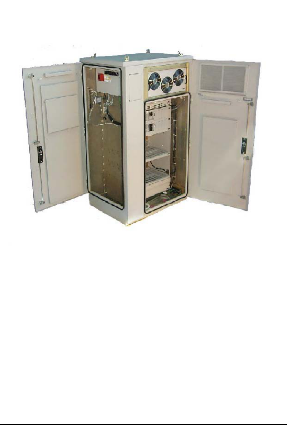
4.2 Digital Enclosure
The DE is the main structural component in the MCBTS. The digital enclosure will
house the rectifiers, equipment shelves, internal heating/cooling tray, heat exchanger
internal loop fan assembly and provide for all necessary internal cable routing
management.
The preliminary outside dimensions for the DE are illustrated below. These dimensions
refer to the unpackaged height and are excluding the DEI which attaches to the left side
and the heat exchanger which mounts on the top.
The dimensions are:
• Depth: 30”
• Height: 57” Max (excluding 15” high heat exchanger)
• Width 30”
The DE with no shelves will weigh an estimated 190 lbs.
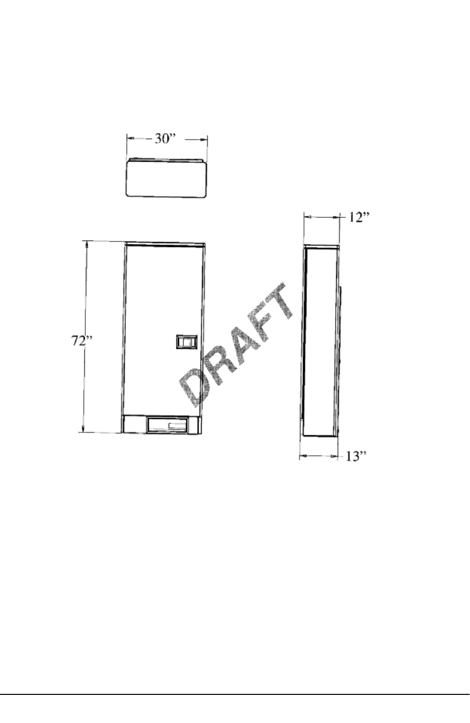
4.3 Digital Enclosure Interface
The Digital Enclosure Interface (DEI) for the MCBTS enclosure assembly provides
entrance of the AC power, network and alarm connections, and connection to the
ground ring. The dimensions of the DEI are shown below.
The dimensions are:
• Depth: 30” (same as overall depth of Digital Enclosure)
• Height: 72”
• Width 12”
The weight of the empty DEI is estimated to be 225 lbs. The loaded module weight after
integration of equipment is expected to be 700 lbs. Cable access to the DE is via DE
interface (DEI).
METRO CELL OUTDOOR (DE/RE) CDMA BTS RADIO DEVELOPMENT
PROPRIETARY CELL SITE REQUIRE-
Feb. 2001 - 8 - Issue 01 Stream 00
4.4 External Battery Cabinet
The MCBTS external battery cabinet (EBC) is an optional stand alone enclosure that
provides additional battery backup to the digital enclosure. It will be located adjacent to
the DE at the installation site and allow for one additional EBC to be daisy chained
together to provide additional battery backup.
The EBC utilizes the DE as its external enclosure for environmental protection. four
lifting eyes are provided at the top of the EBC for installation at the cell site.
METRO CELL OUTDOOR (DE/RE) CDMA BTS RADIO DEVELOPMENT
PROPRIETARY CELL SITE REQUIREMENTS
Issue 01 Stream 00 - 9 - Feb. 2001
METRO CELL OUTDOOR (DE/RE) CDMA BTS RADIO DEVELOPMENT
PROPRIETARY CELL SITE REQUIRE-
Feb. 2001 - 10 - Issue 01 Stream 00

METRO CELL OUTDOOR (DE/RE) CDMA BTS RADIO DEVELOPMENT
PROPRIETARY CELL SITE REQUIREMENTS
Issue 01 Stream 00 - 11 - Feb. 2001
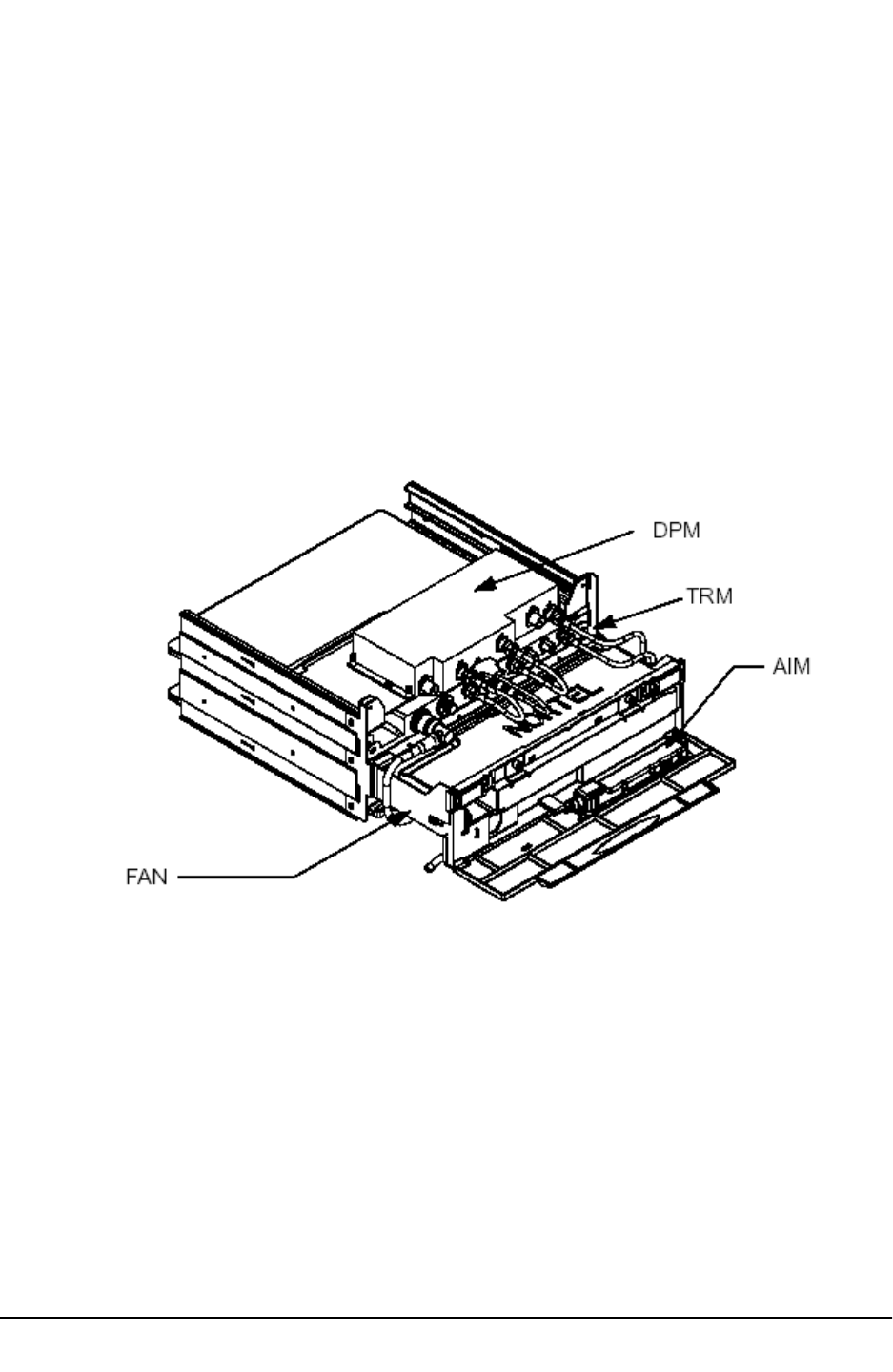
4.4.1 FRM
The FRM is illustrated in Figure xyz.
Each FRM consists of the following main components: duplexer pre-selector module
(DPM) or triplexer module, transmit receive module (TRM), power amplifier module
(PAM) and fan/plenum assembly. The alarm indicator module (AIM) is located within the
fan unit housing. The PAM, TRM, and fan unit have the same mechanical dimensions for
both 800 MHz and 1900 MHz configurations. The 800 MHz DPM is taller than the 1900
MHz DPM.
.
4.5 General Cabinet Anchoring
The DE is designed to be hoisted by a crane. Four mounting points are provided on the
top of the cabinet for hoisting.
4.6 Pad mounting
The MCBTS shall be mounted on a concrete slab
4.7 Rubber Isolation Pad
The DE shall be mounted on a rubber pad.

METRO CELL OUTDOOR (DE/RE) CDMA BTS RADIO DEVELOPMENT
PROPRIETARY CELL SITE REQUIRE-
Feb. 2001 - 12 - Issue 01 Stream 00
5.0 AC Power Requirements
5.1 Power Specifications
Commercial AC power will be supplied to the DE as a single/split-phase, 120/240 Vac
nominal, or 120/208 nominal Vac two of three phases, four conductor (L1, L2, Neutral
and Ground) connection from an external service entrance.
The DE ac power input requirements are as follows:
• Nominal Input Voltage: 240/120 Vac, single, split phase, 50/60 Hz
• Input Voltage Range: 178 to 264 Vac
• Input Frequency: 47 - 63 Hz
• Power factor: greater than 90% at nominal line voltage and frequency
• Input current rating 70A, 2-pole circuit breaker
5.2 AC Power Connection
All external AC power enters the system via the AC panel in the DEI. Primary power is by
connection to the AC utility. A four wire (L1, L2, Neutral, and ground), nominal 240/120V
(or 208/120V), 100A rating, ac supply must be supplied by the customer. The main
breaker from the customer supply should be 100A. If the DEI is to be the service
entrance, the neutral-groundjumper in the ac panel should be connected. Otherwise, it
should be removed.
Auxiliary AC power access is via the external AC generator receptacle connector.
.
METRO CELL OUTDOOR (DE/RE) CDMA BTS RADIO DEVELOPMENT
PROPRIETARY CELL SITE REQUIREMENTS
Issue 01 Stream 00 - 13 - Feb. 2001
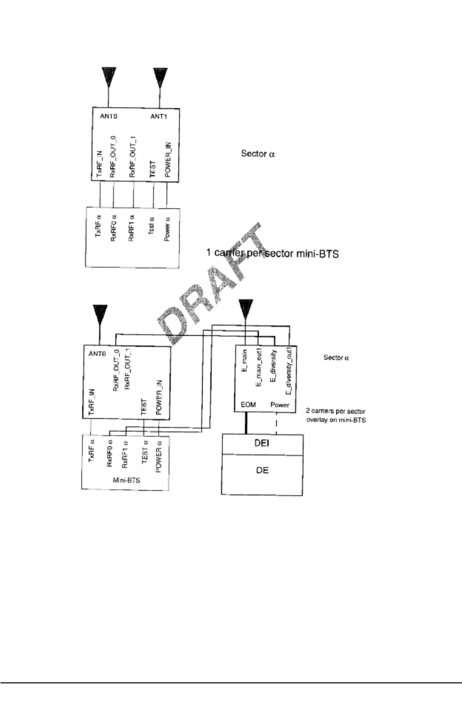
6.0 RF Overlay Requirements
The Metro Cell has several overlay options
Basic installation configuration (single channel)
Simple overlay or mini configuration
The Metro Cell can accommodate 1900 MHz FRM’s, 800 MHz FRM’s, or combinations
of both.
The FRM is illustrated in Figure 16. Each FRM consists of the following main
components: duplexer pre-selector module (DPM) or triplexer module, transmit receive
module (TRM), power amplifier module (PAM) and fan/plenum assembly. The alarm
indicator module (AIM) is located within the fan unit housing. The PAM, TRM, and fan
unit have the same mechanical dimensions for both 800 MHz and 1900 MHz
configurations. The 800 MHz DPM is taller than the 1900 MHz DPM.
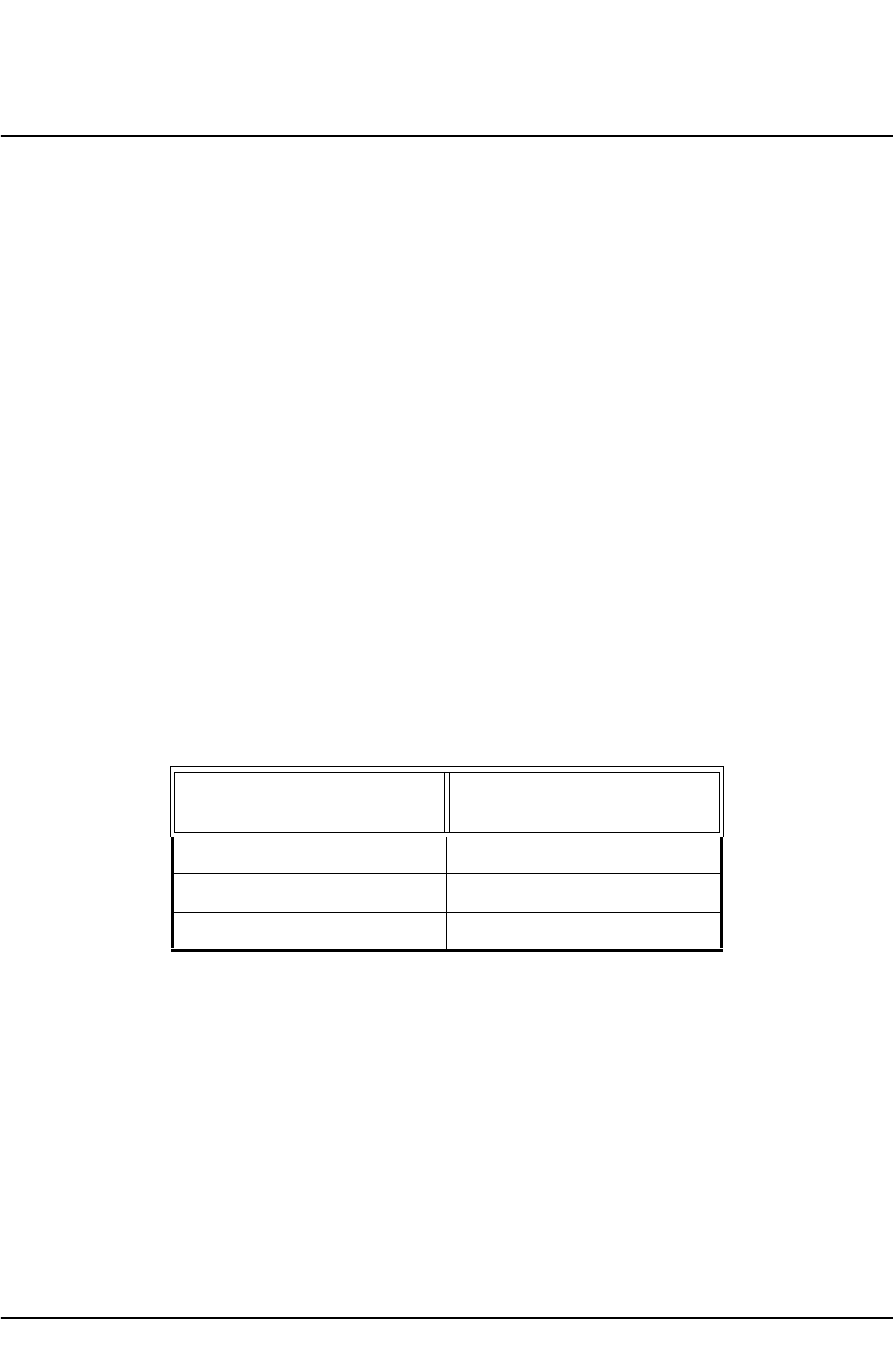
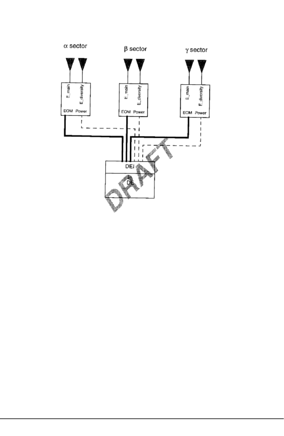
The minimum requirement (1 carrier) is 2 antennas per sector, one for the main path (Tx
and one diversity path) and one for the other diversity path. A two carrier system can also
be supported with two antennas. In this case, each antenna carries one carrier on the Tx
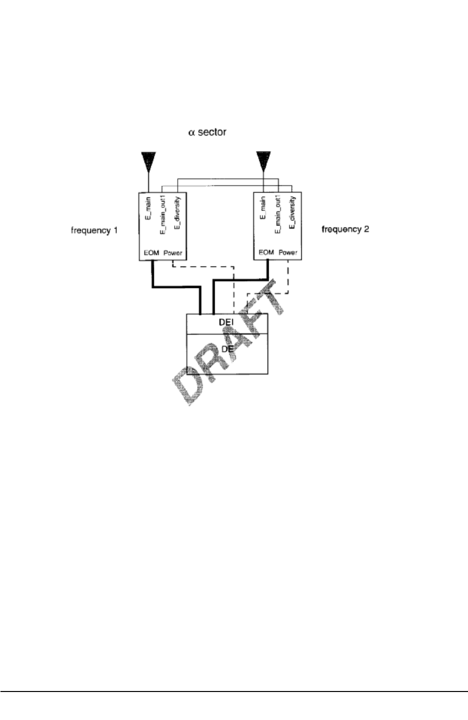
side and one diversity path on the Rx side. With a three carrier system, a third antenna is
added to carry just the Tx of the third carrier
6.1 Cable Connections
The optical link cable, SFRM DC power cable and the GPS antenna cable have a
provisionable length. When ordering, the length must be specified and fall below the
maximum length specifications indicated.
The quantity of inter-DFRM cables required depends upon the application. In a single
carrier system, no inter-SFRM cables are required. In 2 or 3 carrier systems, inter-
SFRM cables are required.
Two sample configurations will be considered for illustrative purposes. These are:
Table 6.1:
Number of Carriers
Number of Antennas per
Sector
12
22
33

METRO CELL OUTDOOR (DE/RE) CDMA BTS RADIO DEVELOPMENT
PROPRIETARY CELL SITE REQUIRE-
Feb. 2001 - 14 - Issue 01 Stream 00
i) a basic system with no redundancy;
ii) a premium system with all redundancy

METRO CELL OUTDOOR (DE/RE) CDMA BTS RADIO DEVELOPMENT
PROPRIETARY CELL SITE REQUIREMENTS
Issue 01 Stream 00 - 15 - Feb. 2001
7.0 GPS Receiver
Timing and frequency reference information provided by the GPS receiver is critical to
the proper operation of Metrocell subsystem. One or two GPS antennas may be
connected. The GPS antenna receives the signals from multiple satellites, and the
signal is supplied to the GPS receiver in the Metrocell via a coaxial cable. Precautions
should be taken to ensure that the GPS antenna is clear of obstructions and
interference.
The antenna should be installed to provide the best view of the entire sky. A complete
view of the sky from horizon to horizon will enable the receiver to observe as many GPS
satellites as possible. This allows the GPS receiver to select the best combination of
GPS satellites for best performance. If the GPS antenna must be installed with a limited
view of the sky, it may not be able to track a sufficient number of satellites to determine
its position. The GPS receiver must track at least 4 satellites simultaneously for some
period of time in survey mode. Once the GPS receiver has an accurate fix on its
location, it can maintain accurate timing signals to the BTS while tracking only one
satellite.
The maximum distance between Metrocell and GPS antenna is set by the maximum
allowable cable loss of? dB. The cable length and type is required by the GPS receiver
for determining the delay from antenna to the receiver.
METRO CELL OUTDOOR (DE/RE) CDMA BTS RADIO DEVELOPMENT
PROPRIETARY CELL SITE REQUIRE-
Feb. 2001 - 16 - Issue 01 Stream 00
Connections and Cabling
METRO CELL OUTDOOR (DE/RE) CDMA BTS RADIO DEVELOPMENT
PROPRIETARY CELL SITE REQUIREMENTS
Issue 01 Stream 00 - 17 - Feb. 2001
METRO CELL OUTDOOR (DE/RE) CDMA BTS RADIO DEVELOPMENT
PROPRIETARY CELL SITE REQUIRE-
Feb. 2001 - 18 - Issue 01 Stream 00
METRO CELL OUTDOOR (DE/RE) CDMA BTS RADIO DEVELOPMENT
PROPRIETARY CELL SITE REQUIREMENTS
Issue 01 Stream 00 - 19 - Feb. 2001

METRO CELL OUTDOOR (DE/RE) CDMA BTS RADIO DEVELOPMENT
PROPRIETARY CELL SITE REQUIRE-
Feb. 2001 - 20 - Issue 01 Stream 00
8.0 Connections and Cabling
8.1 FRM Power Connections and Cables
DC power is conducted to individual FRMs via two conductor (-48V, BR) shielded
(ground) cables, one cable for each FRM. The size of the power cable depends on the
cable run length. The DC power cable from DEI enters the FRM enclosure via the
Power Entry Module (PEM)
The specifications for these external FRM dc cables are as follows:
• less than 3000 feet, use 2 conductor #8 AWG shielded cable
• Between 300 and 600 feet, use 2 conductor #6
• Allowed cable voltage drop: 6 Vdc maximum (-48V and Rtn combined)
• Cable terminations: two-hole lugs at the DEI BRR plate, twist-lock type
connector at FRM (to mate with the PEM)
• Shield termination: grounded at both the FRM and DEI ends, and at the base of
the tower
The FRM DC cable is sized for voltage drop, not ampacity
The optical link enters the FRM via the electro-optic module (EOM)
8.2 FRM Interconnect
Table 8.1 next shows the FRM external interconnect single carrier configuration.

METRO CELL OUTDOOR (DE/RE) CDMA BTS RADIO DEVELOPMENT
PROPRIETARY CELL SITE REQUIREMENTS
Issue 01 Stream 00 - 21 - Feb. 2001
8.3 Fiber
The optical link to the FRM contains 4 fibers per link. two receive and transmit pairs for
redundancy, unless multi carrier deployment is used, when soft redundancy is handled
by the other carrier and only two fiber are used (other two left unused). The main portion
of the link will run on outside plant cable capable of vertical ascent, terminated at the
FRM by a standard SIECOR optifit termination. The transceivers will be housed in a
heated optical termination unit which is connected to the FRM by electrical interconnect.
The high speed signals will be carried by 4 coaxial links.
Fiber interconnect and rearrangement features are required to interconnect the FRMs to
the Digital enclosure. Current baseline design has the digital enclosure provisioned with
a optical link harness, fiber storage and management, as well as flexibility point (splice
point) in the DEI cabinet capable of handling all 48 fibers in the fully configured case.
The FRM has an EOM which depends upon the length of the fiber run from the DE to
the FRM
Table 8.1: FRM Interconnect
Name Type Format # Pins From To Note
E-pwr/ret 48VDC DC 2 DEI FRM E_ in the name
E_gnd GND GND 1 DEI FRM designates a
E_shield GND GND 1 DEI FRM connection
E_rfm_rvs1 639.976 Mbs optical 1 EOM COR1 external to the
E_rfm_fwd1 639.976 Mbs optical 1 COR1 EOM FRM assembly
E_rfm_rvs2 639.976 Mbs optical 1 EOM COR2
E_rfm_fwd2 639.976 Mbs optical 1 COR2 EOM

METRO CELL OUTDOOR (DE/RE) CDMA BTS RADIO DEVELOPMENT
PROPRIETARY CELL SITE REQUIRE-
Feb. 2001 - 22 - Issue 01 Stream 00
9.0 T1/E1 Connections
The CM module has up to 6T1 interfaces connected through the backplane. The cable
will probably be lumped in two 12 wire bundles terminated at the digital shelf backplane
by two 15 pin dsubs.
The Metro Cell can be connected to the BSC using 1 to 6 T1/E1 links. These T1/E1
links are distributed between the two DCGs i.e. if one DCG has 4 T1/E1s connected to it
then the other can have a maximum of two T1/E1 links. All T1/E1s connected to each
DCG need to have the same timing reference at the BSC. Each link requires 2 twisted
pairs.
There are two ways of connecting T1/E1 to the Metro Cell. The T1/E1 cables can be
directly brought into the DEI or they can be connected to a RJ48H connector which
interfaces with the DEI. The RJ48H connector cable NTGS0106 is provisionable. In the
DEI T1/E1 connections are done on the middle and lower blocks among the three
Telephone/Data Line Protection blocks as shown in Figure 87. The RJ48H connector is
shown in Figure 88 and the pinout is shown in Table 30.
The number of T1/E1s that need to be connected to the Metro Cell depends on the call
carrying capacity of the T1/E1s and the number of calls that a Metro Cell has to make.
The number of T1/E1 that need to be provisioned for a Metro Cell can be determined
from Ref [10].
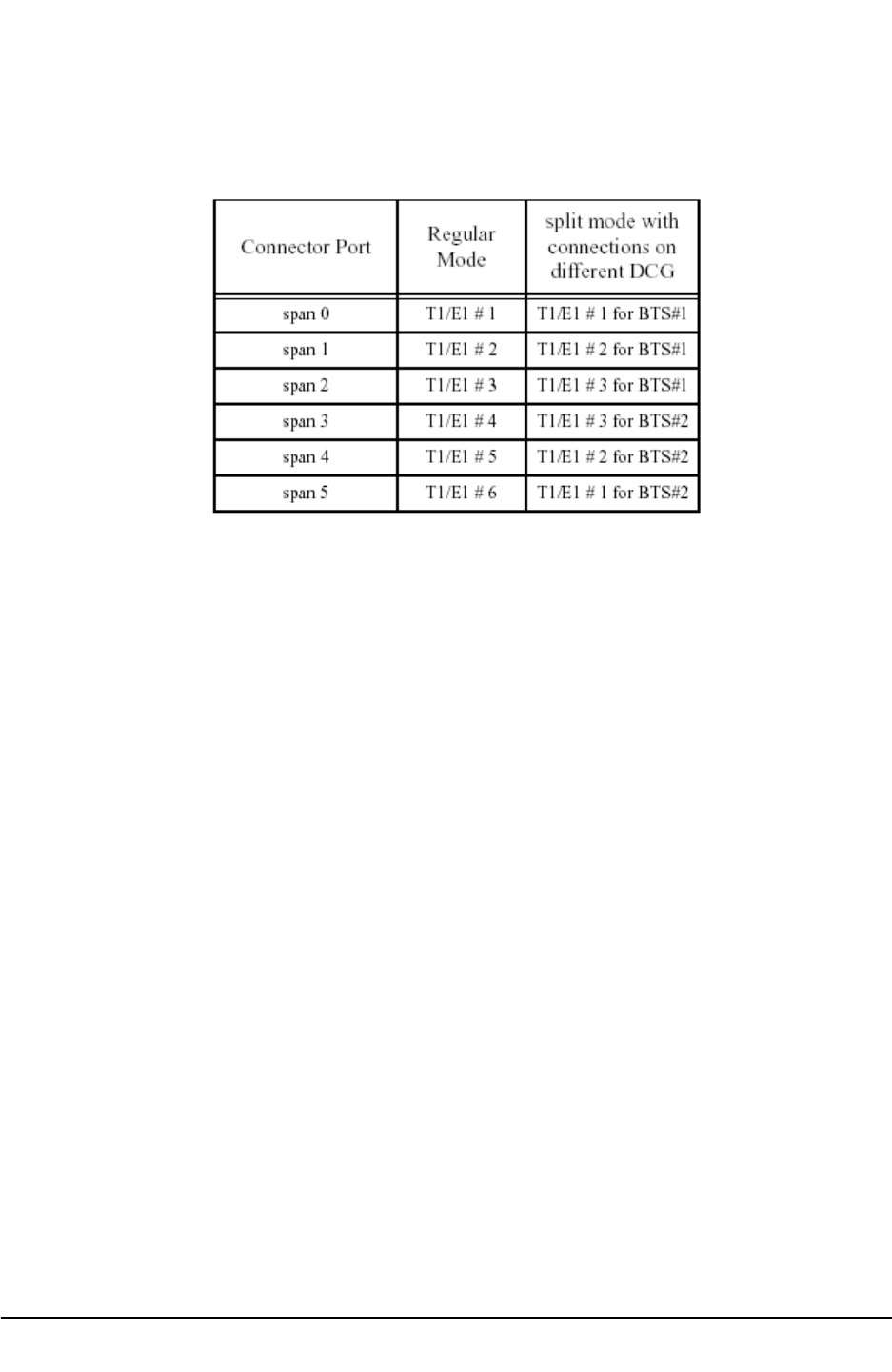
The two modes of operation of Metro Cell are regular (or non-split) mode or split mode.
In the regular mode only one DCG is active, the other DCG may not be provisioned or is
a redundant DCG. In the split mode both DCGs are provisioned and are active. Each
DCG in the split mode is a logical BTS. The T1/E1 connections of the Metro Cell in the
regular and split mode are done as shown in Table 27.
The T1/E1 lines are connected to one of the two BTSI cards in the control module (CM)
METRO CELL OUTDOOR (DE/RE) CDMA BTS RADIO DEVELOPMENT
PROPRIETARY CELL SITE REQUIREMENTS
Issue 01 Stream 00 - 23 - Feb. 2001
Table 27: T1/E1 Connections of Metro Cell without Daisy Chaining
The T1/E1 lines are connected to one of the two BTSI cards in the control module (CM)
which forms part of the DCG. The connections are controlled by relays and are exclusive
to one DCG. Therefore if T1/E1 #1 is connected to the first DCG then the same lines
cannot be connected to the other DCG. This is true in regular as well as split mode. In
regular mode since only one DCG is active, therefore, all the T1/E1s are connected to
the active DCG. When the redundant DCG takes over then the connections are switched
to it by closing the relays on this new active DCG and opening them on the previously
active DCG. The middle column of Table 27 shows how the T1/E1 connections are done
for the active DCG in regular mode. In the split mode each DCG is active and is part of
the logical BTS. Therefore, each DCG has its own independent T1/E1 connections. The
right column of Table 27 shows how the T1/E1 connections are done for the two logical
BTSs in the split mode. It is clear from [1] that a single DCG, supporting a maximum of
two carriers, does not need more than 3 T1/E1 connections. So, the connections shown
in Table are reasonable and will provide for a redundant T1/E1 link per logical BTS in
most cases (keeping in mind the number of T1/E1 links needed for 2 carriers as
mentioned in [10]).
The Metro Cell can be configured for a shorthaul link or a longhaul link. In case of a
shorthaul configuration the Metro Cell should be within 655ft of the last repeater while for
a longhaul link the Metro Cell should be within 6000ft of the last repeater using 22 gauge
unshielded twisted pair cable i.e. 100 ohm 22 gauge cable. The shorthaul and longhaul
link is configured using software. The distance of the Metro Cell from the last repeater-

METRO CELL OUTDOOR (DE/RE) CDMA BTS RADIO DEVELOPMENT
PROPRIETARY CELL SITE REQUIRE-
Feb. 2001 - 24 - Issue 01 Stream 00
has to match the software configuration.

METRO CELL OUTDOOR (DE/RE) CDMA BTS RADIO DEVELOPMENT
PROPRIETARY CELL SITE REQUIREMENTS
Issue 01 Stream 00 - 25 - Feb. 2001
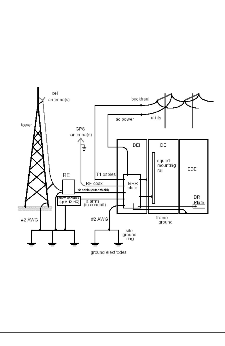
10.0 Grounding
10.1 BTS grounding Architecture
The FRM is grounded to its mounting structure, whether a tower, wall, building or pole.
for outdoor Metrocell or the radio rack (Indoor Metrocell). If the structure is non-
conductive (e.g. wooden pole) it shall be provided with a ground cable as part of the site
ground.
The FRM mounting structure and BTS cabinets both connect to the site ground ring. #2
AWG cables less than ten feet long are used for these primary, external ground
connections.
10.2 Antenna Grounding
Each GPS antenna will be grounded at the antenna mast and again at the cable entry
point (coax cable shield) inside the DEI. Similarly, the cell site antenna(s) are grounded
at the tower and may be further protected by lightning rods on the mounting structure,
protruding above the antennas, preventing direct strike to the.
10.3 Radio rack Grounding
The common ground point in the RE is the subframe. A #2 AWG cable will connect the
subframe to the main ground point in the DEI in the side-by-side configuration. When the
RE is installed remotely from the DEI/DE the ground cable will connect the subframe to
the site ground in that area. Attachment shall be made with two hole compression lugs.
The shield of the DC power cable connecting the main electronics cabinet to the FRM
shall be grounded at both the FRM end and the main enclosure end (main ground plate)
.
Provision one NTGS0161 main site ground cable for the DEI/DE and one for every RE.
10.4 Site Ground Ring
A peripheral grounding ring, usually buried around the site perimeter, or routed along
the outer edge of the roof of a building, provides the main site ground. It provides an
equipotential reference to minimize differential voltages during lightning surges. It
consists of a #2 AWG (or larger) uninsulated, tinned copper conductor. Connections are
made to it using C-tap clamps.
METRO CELL OUTDOOR (DE/RE) CDMA BTS RADIO DEVELOPMENT
PROPRIETARY CELL SITE REQUIRE-
Feb. 2001 - 26 - Issue 01 Stream 00
The ground ring makes earth contact through ground electrodes, typically copper-clad
stakes 3m (10 ft.) long, driven into the ground at 2.5 to 3m (8-10 ft.) intervals around the
ground ring and tower, and welded to it. The resistance to earth of the ground ring shall
be 25 ohms or less, with a preferred value of less than 5 ohms. See Nortel CS4122.00
and DSAP65BA (Cell Site Power and Grounding) for further information.
_____________________
Fig. 10.1 Cell Site Grounding Connections

METRO CELL OUTDOOR (DE/RE) CDMA BTS RADIO DEVELOPMENT
PROPRIETARY CELL SITE REQUIREMENTS
Issue 01 Stream 00 - 27 - Feb. 2001
11.0 References
[1] CMS-MTX/CDMA MCBTS 1900 Outdoor and MCBTS Base Platform. Product
Specification Agreement. by Neil McGowan and Frank van Heeswyk.
[2] CDMA MCBTS 1900 Outdoor. Power Protection and Grounding Design Specification.
by Ed Norman
.
[3] CDMA MCBTS 1900 Outdoor. General Specification.
[4] MCBTS 1900 MHz Radio Enclosure System Packaging Specification. by Fred Folk.
[5] MCBTS Optical Link NTGS05AA, NTGS0117, NTGS0095 Functional Agreement.
Packaging Concepts Methodology.
[6] MCBTS Digital Enclosure Mechanical Assembly NTGS13AA Functional Agreement.
Packaging Concepts Methodology.
_____________________