Avaya Canada NT800FRM 800 MHz CDMA Flexible Radio Module for Base Stations User Manual Corp Sig 9p6 blk
Avaya Canada Corporation 800 MHz CDMA Flexible Radio Module for Base Stations Corp Sig 9p6 blk
Exhibit 5 User Documentation

This document contains Proprietary Information of Northern Telecom Limited. This information is considered to be
CONFIDENTIAL and should be treated appropriately.
EXHIBIT 5
User Documentation
Applicant: Northern Telecom Ltd.
For Type Acceptance/Certification on:
AB6NT800FRM

CDMA
Metro Cell
Functional Description Manual
NBSS7.1 Prototype 01.04 November 1998
411-2133-110
PROTOTYPE


CDMA
Metro Cell
Functional Description Manual
Product release: NBSS7.1
Document release: Prototype 01.04
Date: November 1998
Document Number: 411-2133-110
Copyright Country of printing Confidentiality Legal statements Trademarks
1998 Northern Telecom
Printed in the United States of America
NORTHERN TELECOM CONFIDENTIAL: The information contained in this document is the property of Northern
Telecom. Except as specifically authorized in writing by Northern Telecom, the holder of this document shall keep the information
contained herein confidential and shall protect same in whole or in part from disclosure and dissemination to third parties and use
same for evaluation, operation, and maintenance purposes only.
Information is subject to change without notice.
Metro Cell, DMS-MTX, and MAP are trademarks of Northern Telecom.

iv
411-2133-110 Prototype 01.04 November 1998
Publication History
June 1998
01.01 Draft release.

v
CDMA Metro Cell Functional Description Manual NBSS7.1
Contents
Related documents xi
Introduction to Metro Cell 1
Metro Cell product objectives 1
Key features 1
Physical layout of outdoor Metro Cell 6
Physical layout of Indoor Metro Cell 8
Digital equipment architecture 12
Environmental control 14
Thermal design 14
Indoor digital rack (DR) of the Metro Cell 17
Outdoor radio enclosure (RE) physical architecture 19
Module interrelationships 22
Subsystem description 25
Outdoor Metro Cell power systems 25
DEI physical layout 25
Backhaul interface 26
Surge protection 26
AC power entry and distribution 26
DC power and distribution 27
Power, protection and grounding architecture 28
Backup batteries and sensors 28
Indoor Metro Cell power systems 30
AC power Input 30
DC power input 33
DC power distribution (FRMs) 33
Indoor and outdoor Metro Cell distribution module 35
Battery management 39
Power distribution 40
Grounding 42
Battery backup 42
CEM principle functions 43
CEM Interconnect board (IB) 47
CEM dc voltages 47
Timing and frequency systems 47
Global positioning system timing module (GPSTM) 47
Antennas 50
Gps antennas 50

vi Contents
411-2133-110 Prototype 01.04 November 1998
Control Module (CM) 50
CDMA traffic systems 51
CORE 51
Flexible RF modules (FRM) 55
Transmit / Receive Module (TRM) 59
Duplexer/LNA Preselector/LNA Module (DPM) - 1900 MHz 60
Duplexer/LNA module - 800 MHz 62
1900 FRM Triplexer Module (FRMTM) 63
Electro-optical Module (EOM) 64
Power amplifier (PAM) 65
Fan / alarm controller board 65
Basestation communication network (BCN) distribution 67
DE / RF module signalling 70
Signal flow 70
Forward link baseband signal flow 70
Field Replaceable Units (FRU) 71
Outdoor Metro Cell 72
Software 77
Specifications 79
Glossary 81

Contents vii
CDMA Metro Cell Functional Description Manual NBSS7.1
Figures
Figure 1 Metro Cell modular overview 3
Figure 2 System interconnect 4
Figure 3 System interconnect layout 5
Figure 4 Outdoor Metro Cell digital enclosure 7
Figure 5 Outdoor Metro Cell Physical Layout 8
Figure 6 Indoor Metro Cell Packaging 9
Figure 7 Indoor EOM to CORE optical link cable routing DR/RR
collocated 10
Figure 8 FRM optical link cable routing 11
Figure 9 EOM to CORE fiber cable assembly 12
Figure 10 Digital shelf (bottom) graphic 13
Figure 11 Outdoor Metro Cell layout of thermal control system
components 16
Figure 12 Digital rack 17
Figure 13 Indoor cabinet airflow 18
Figure 14 Radio enclosure 21
Figure 15 Module relationships 23
Figure 16 Layout of components in DEI 25
Figure 17 AC circuit breaker panel box in the DEI 27
Figure 18 Power protection and grounding block diagram 29
Figure 19 Metro Cell power and grounding interconnections 30
Figure 20 Indoor AC power architecture 31
Figure 21 AC system bulkhead 32
Figure 22 Indoor ac Metro Cell packaging 33
Figure 23 Indoor dc power architecture 34
Figure 24 Indoor system dc bulkhead 35
Figure 25 Power shelf (graphic) 36
Figure 26 Rectifier shelf - cover closed 37
Figure 27 Open rectifier shelf 38
Figure 28 Breaker sticker 39
Figure 29 Power distribution block diagram 41
Figure 30 Battery storage frame 42
Figure 31 Digital equipment shelf (top) graphic 44
Figure 32 CEM shelf 45
Figure 33 CEM diagram 46
Figure 34 Timing distribution 49
Figure 35 Global positioning system timing module (GPSTM) 50
Figure 36 NTGS30AA CORE module and CORE module with open
faceplate 53
Figure 37 CORE block diagram 54
Figure 38 Flexible RF module 56
Figure 39 Layout of FRM connectors 57
Figure 40 Flexible radio module (FRM) block diagram 59
Figure 41 Transmit / receive module internal layout 60
Figure 42 General DPM drawing - 1900 MHz 61
Figure 43 General 800 DPM drawing 63
Figure 44 Electro-optical module 64
Figure 45 Power amplifier module - internal layout 66

viii Contents
411-2133-110 Prototype 01.04 November 1998
Figure 46 Basestation communication network (BCN) distribution 69
Figure 47 DE/RF module signalling 70
Tables
Table 1 FRM indicator assignments 67
Table 2 Outdoor Metro Cell FRU list 72
Table 3 Indoor Metro Cell FRU list 73
Table 4 FRM Metro Cell FRU list 74

ix
CDMA Metro Cell Functional Description Manual NBSS7.1
About this document
This document describes in detail the architecture and basic operation of the
Multi Carrier Base Station Transceiver Subsystem (Metro Cell). It is organized
as follows:
• Introduction to Metro Cell—CDMA concepts are described in general
terms, and multicarrier concepts are introduced.
• Metro Cell high-level overview—the physical layout of the Metro Cell is
described here, beginning with cabinets (DE and FRM) then individual
shelves. This section also includes a complete listing of FRUs and their
PECs.
Subsystem description—This section describes the Metro Cell in terms of the
functional relationships of its subsystems; it gives you a framework for
understanding what the Metro Cell does, and relates the physical components
of the Metro Cell to what they do as part of the overall product.
FRU-level descriptions are provided, and significance of indicators and
configurable hardware options are described.
The following subsystems are covered:
• Power, protection and grounding (batteries, rectifiers);
• Environmental control systems (heating, cooling);
• Timing and frequency systems (GPSTM);
• Backhaul (CM—T1/E1, BCN);
• CDMA Traffic systems (CEMs, CORE);
• RF system (FRM: TRM, HPA, DPM, EOM, fans);
• Hardware alarm reporting systems (AIM in DE, AIM—or alternate
design implementation—in FRM cabinet);
• Signal distribution and optical interface (CORE, EOM)
• Signal path architecture.
• Specifications—information such as height, weight, power, compliance,
and capacity.
1

x
411-2133-110 Prototype 01.04 November 1998
• List of terms—a listing of acronyms, abbreviations, and pertinent
terminology with definitions and descriptions for each.
1

xi
CDMA Metro Cell Functional Description Manual NBSS7.1
Related documents
BSM User’s Guide, NTP-411-2133-103
BSM Configuration Management User’s Guide 411-2133-104
CDMA NBSS Software History and Delta for Planners Manual,
411-2133-199
Fault Management and Recovery Guide, 411-2133-545
Metro Cell Maintenance and Troubleshooting Guide, 411-2133-550
NBSS Alarm Reference Manual, 411-2133-530

xii
411-2133-110 Prototype 01.04 November 1998

1
CDMA Metro Cell Functional Description Manual NBSS7.1
1Introduction to Metro Cell
The Metro Cell is NORTELs second generationWireless CDMA Multi-
Carrier Base Transceiver Station product. This family of products is designed
to cover outdoor and indoor deployment opportunities at both 800 and 1900
MHz.
Metro Cell product objectives
• to offer a product which can address multi-carrier deployments while
offering reduced entry cost for a single frequency system.
• to provide a system which offers a simple and well defined upgrade path
for both the existing product and future generations.
• to offer a product which has the flexibility to be used within numerous
different applications with little or no additional development.
• to reduce BTS maintenance, operating and installation costs
• offer superior system performance.
Key features
The Metro Cell incorporates the following key features:
• outdoor operation.
• indoor operation.
• AC operation or DC operation
• digital system supports up to 4 RF carriers from one platform.
• capable of operating cellular (800MHz) and PCS (1900 MHz) band.
• remotable RF equipment with a digital interconnect link via optical
• EMC containment at a module level.
• reduced interconnect (“skinny”) backplane to simplify interconnect and
product packaging evolution.
• overlays with current CDMA products.
• optional redundancy is available.
• extensive re-use of software from existing CDMA BTS.
1

2 Introduction to Metro Cell
411-2133-110 Prototype 01.04 November 1998
• the Metro Cell design is modular in nature to allow for simple, cost
effective expansion from single to multi-carrier operation.
• complete digital system up to electrical IF stage.
• channelizer in RF equipment - performs transceiver level DSP and
channelization of the CDMA forward and reverse links.
• fiber optic interface for I & Q baseband routing.
• environmentally hardened IF - RF TX and RX modules.
• HPA is an ultra-linear amplifier which meets strict emission requirements
of IS95.
• digital equipment-to-radio equipment separation of up to 200 m. or
approximately 650 ft. using optical fiber.
A diagram of the modular overview of a Metro Cell is shown in Figure 1.
1
Introduction to Metro Cell 3
CDMA Metro Cell Functional Description Manual NBSS7.1
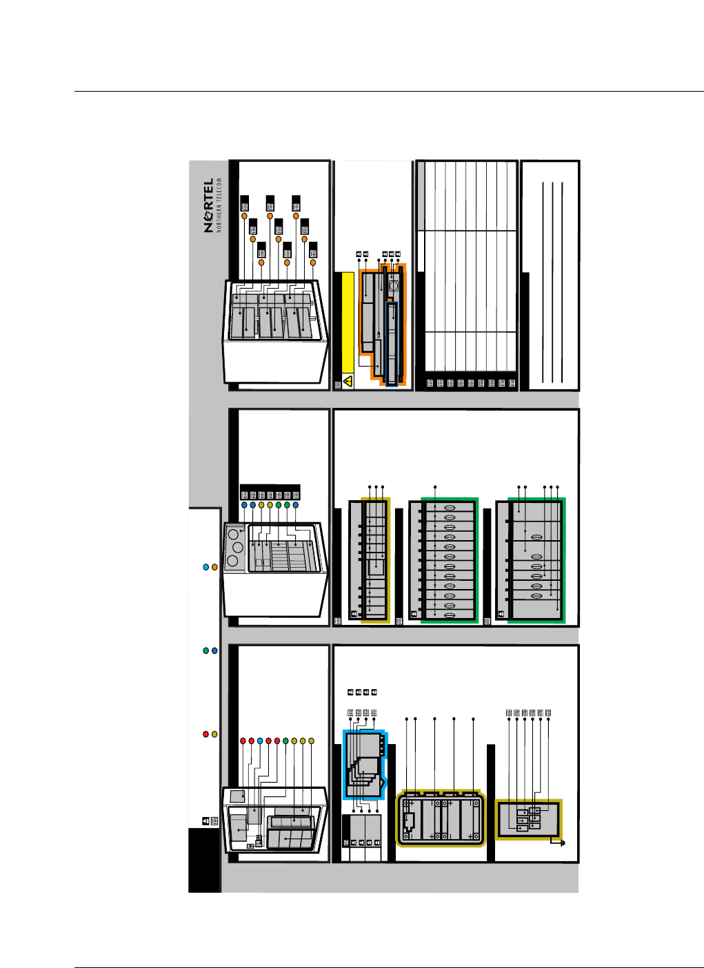
Figure 1
Metro Cell modular overview
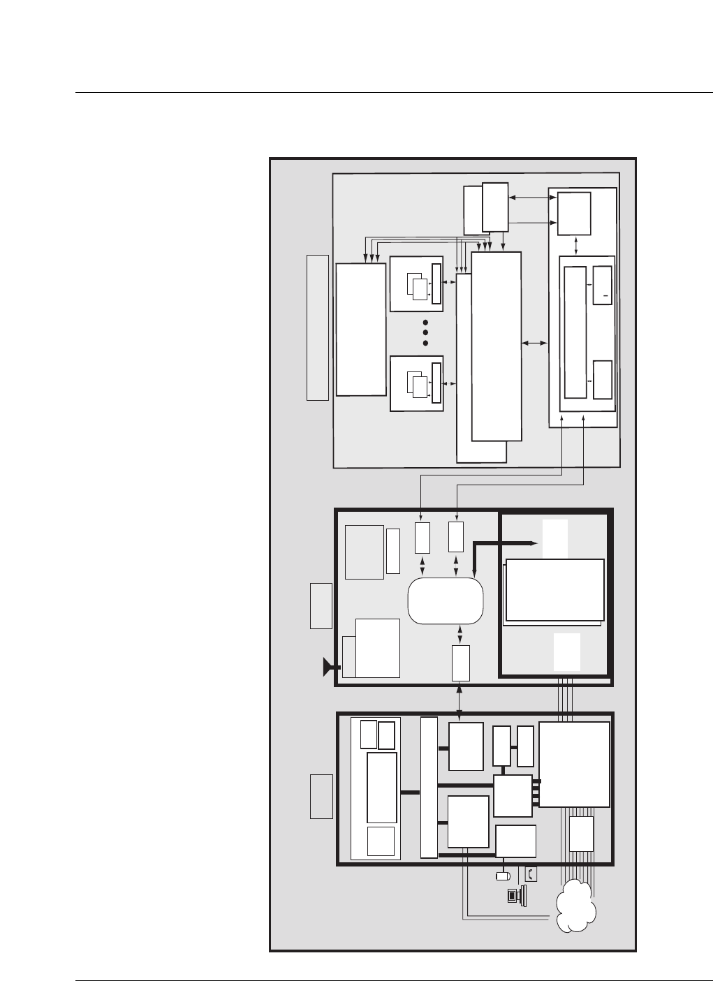
Figure 2 is a block diagram showing how the Metro Cell interfaces to the
BSC and MTX.
Legend
6 CORE 1
7 CORE 2
6 CORE 1
7 CORE 2
2
Cable
Hrns.
1
Cable
Hrns.
2
Splice Tray Interconnect
1234
Tray
FRM
FRM
FRM
FRM
T1/E1
T1/E1
Alarm
Alarm
Battery Interface Module
I,L FRM
C,F FRM
H,K FRM
B,E FRM
A,D FRM
G,J FRM
Backup Batteries, T1/E1 Interconnect
DC Protector
Generator Access Door
AC Power Dist. Panel
Fiber Splice Mgmt.
AC Protector
Convenience Outlet
BMU Ports
Alarm & T1/E1 Interconnect
DC Protector
Backup Batteries
Digital Enclosure Interface
Outer Heat Exchanger
Inner Heat Exchanger
Rectifier (Extension)
Rectifier (Primary)
CEM
GPSTM, CM, CORE
Cooling Unit
7
6
5
4
3
2
1
123456789
Rect: Rectifier Modules
DC Power Distribution Panel
Ctlr: Controller Module
12345678910 11 12
CEM: Channel Element
Modules
12345678
Power/Alarm Interconnect
CM: Control Modules
GPSTM: GPS Timing Modules
CORE: COnfiguration
REsource Modules
T1 Interconnect
3 CEM
4, 5 Rect
Digital Enclosure
2 GPSTM, CM, CORE
I
G
H
E
F
C
D
A
B
Sector Channel NumberFRM
Site Location Information
Remarks
AC Power System
DC Power System
Digital Modules
Environmental Control
Cable Interface
RF Components
Shelf/Group/Cluster
Slot/Field Replaceable Unit
Radio Enclosure
MCBTS
TRM: TRanceiver Module
DPM: Duplexer Preselector
Module
PAM: Power Amplifier Module
FAM: Fan and Alarm Indicator
Module
EOM: Electro-Optic Module
FRM: Flexible Radio Module
FRM can only sustain 5 minutes of operation
without a functioning FAM
XDM Port
EOM
EOM
EOM
EOM
FRM
I
FRM
E
FRM
F
*For sectors configuration, see below.
FRM
G
FRMA
FRMB
FRM
H
FRM
C
FRM
D
METRO CELL
**
** can be with or without preselector
alternatively Triplexer for the 1900 or a
Combiner for the 800.
4 Introduction to Metro Cell
411-2133-110 Prototype 01.04 November 1998
Figure 2
System interconnect
FRM
CEM CEM
CORE Module 1
CORE Module 2
GPS
Module
GPS
Module
BTSC
BTSI
Router
(BCN DISCO Functionality)
T1/E1 uP
Control Module
BSM
Modem
GPSR
Timing and
Frequency
Unit
DISCO CDSU
CDSU
CDSU
Selector
Cards
1 - 12
SBS
Shelf
SCIs
SBS
Controller
Card
BSC
SLM
DMS CORE
Computing
Module
HLR
VLR
DMS Bus
LPP LPP
or FLIS
IOC ENET MTM
OAU
Digital
Trunk
Controller
T-1s
UnC
T-1
MTX
CDMA Metro Cell System Interconnect Diagram
UnC
T-1
CDMA Metro Cell
CCS7 Link
to other MTA9s)
Map
T-1
Voice
Trunks
PSTN
Redundant
I/F I/F
24 CE 24 CE
Introduction to Metro Cell 5
CDMA Metro Cell Functional Description Manual NBSS7.1
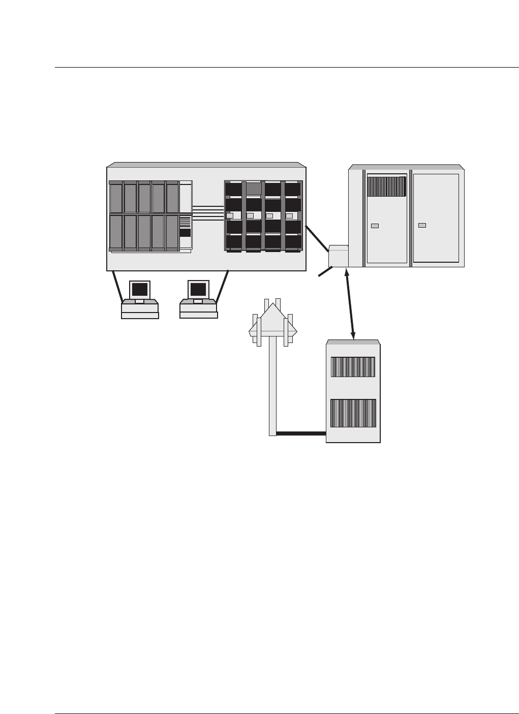
Figure 3 shows the high level relationship between the Metro Cell and Mobile
Switching Center (MSC).
Figure 3
System interconnect layout
Digital Enclosure
(DE) Optional battery
Digital Enclosure
Interface (DEI)
DMS - MTS
MSC
BSC
T1
T1
Enclosure
Up to
200 meters
separation
Radio Enclosure (RE)
MAP BSM

6 Introduction to Metro Cell
411-2133-110 Prototype 01.04 November 1998
Physical layout of outdoor Metro Cell
The Metro Cell 1900 Outdoor consists of two main cabinets (DE/RE) and
exploits modular design concepts. Five types of modules are defined: Flexible
Radio Modules (FRM), Channel Element Modules (CEM), Control Modules
(CM), COnfiguration REsource modules (CORE), and Global Positioning
System Timing Modules (GPSTM).
The CEM, CM, CORE, and GPSTM are housed together in a digital frame.
The RF equipment is packaged in a separate, environmentally hardened
cabinet, and may be located remotely from the digital cabinet. This cabinet
accommodates up to nine FRM modules, each of which supports the RF air
interface for a single CDMA sector. FRM module frequency assignments are
defined on a per module basis, so a fully populated FRM cabinet could
support three carriers/three sectors or some other combination up to nine
sectors. Accommodating a fourth carrier in a three-carrier/three sector Metro
Cell requires a second FRM enclosure with up to three modules.
The Digital Enclosure cabinet for the outdoor version is shown in Figure 4
and Figure 5.

Introduction to Metro Cell 7
CDMA Metro Cell Functional Description Manual NBSS7.1
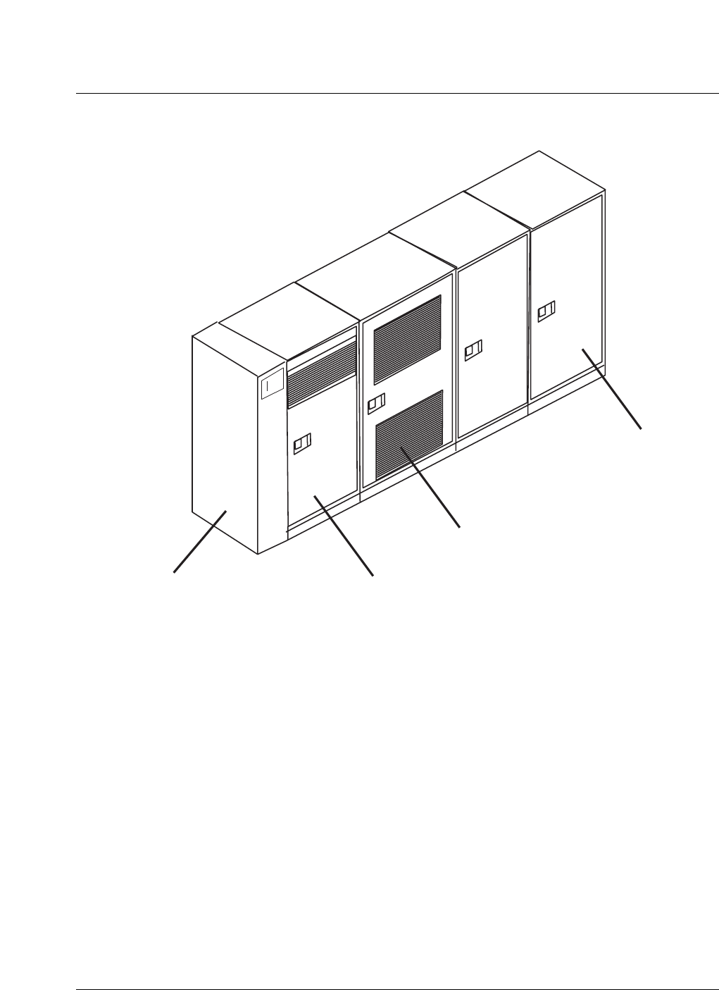
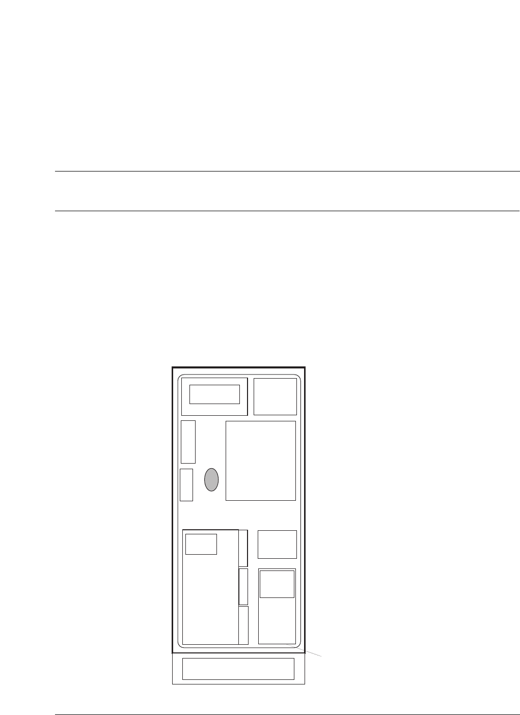
Figure 4
Outdoor Metro Cell digital enclosure
DEI
Fiber splice
box
Optional
batteries
short duration Equipment
shelves
8 Introduction to Metro Cell
411-2133-110 Prototype 01.04 November 1998
Figure 5
Outdoor Metro Cell Physical Layout
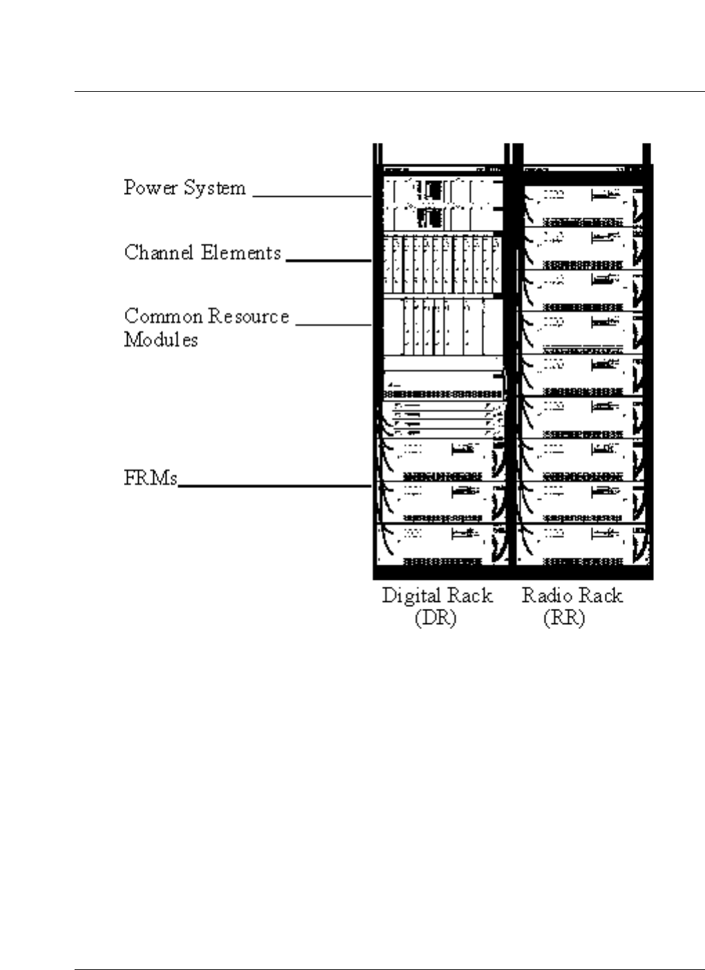
Physical layout of Indoor Metro Cell
The CEM, CM, CORE, and GPSTM modules are housed together in a digital
rack. The Digital Rack (DR) houses the AC rectifiers or DC breaker panel for
the required power supply system. The DR can also accommodate 3 FRMs;
thus resulting in a fully equipped 3-sectored, 1 carrier Metro Cell in one rack.
The overall physical layout is shown in Figure 6.
Optional
Battery
Cabinets
Radio
Enclosure (RE)
Digital
Enclosure (DE)
DE Interface
(DEI)
Introduction to Metro Cell 9
CDMA Metro Cell Functional Description Manual NBSS7.1
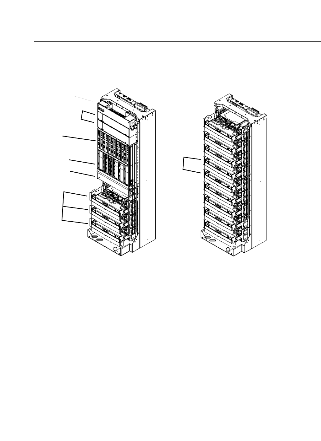
Figure 6
Indoor Metro Cell Packaging
Each FRM is connected to the digital rack via a four-fiber optical cable
carrying digital Tx and Rx baseband data and control signalling. At the digital
rack, these cables are terminated directly on the CORE modules (not at the
bulkhead).
Connectorized fiber-optic patch cables are provided to support configurations
in which the digital and radio racks are located side-by-side or up to 650 feet
apart. For applications where the radio rack is located farther away from the
digital rack, cable splicing is required. The connectorized patch cables can be
spliced to FRM cables of length 20 meters or 200 meters. A splicing tray can
be mounted either on a wall or in the digital rack. The maximum cable run
length is 200 meters.
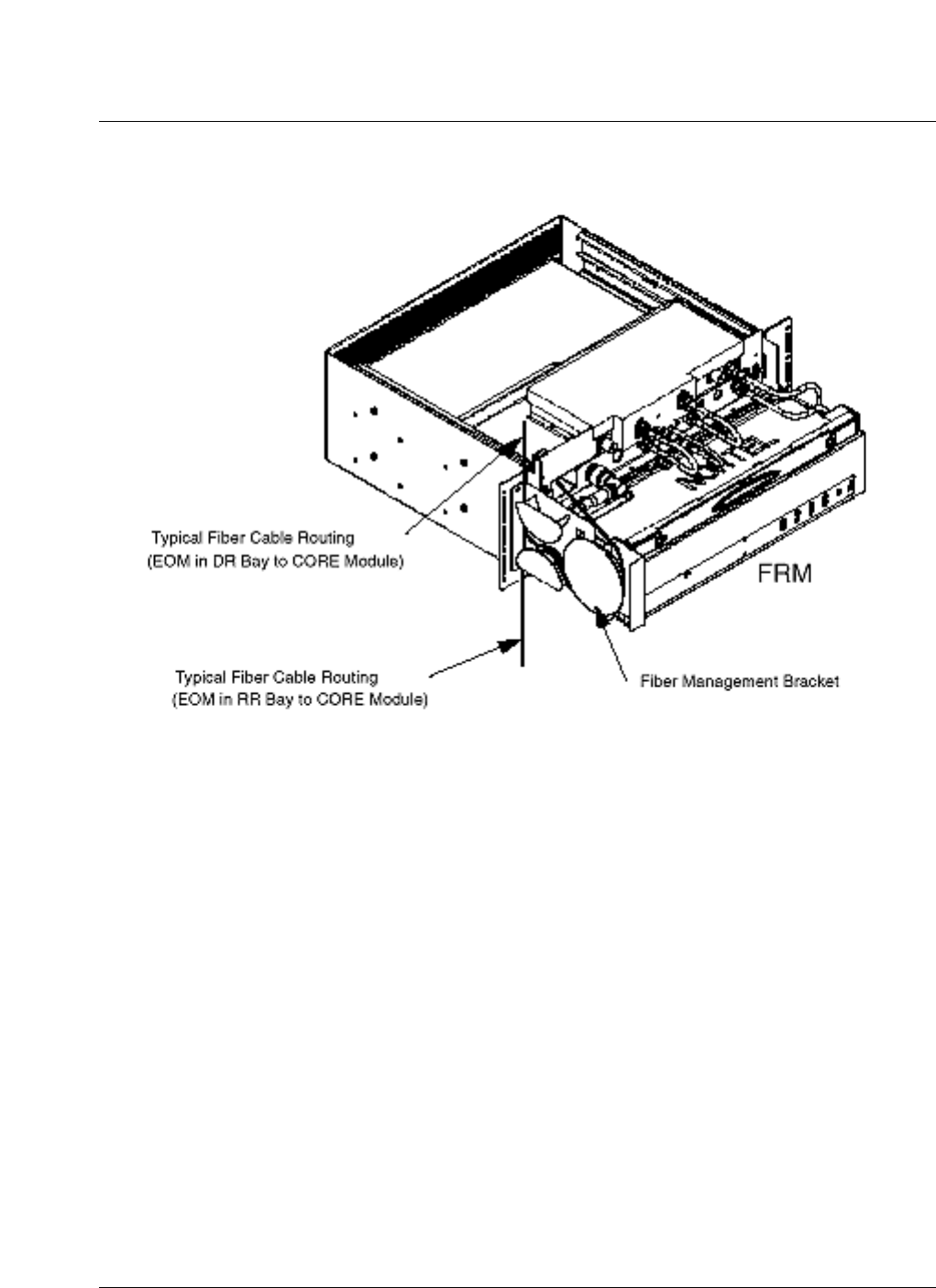
Each FRM shelf is configured with an integral fiber management bracket
designed to route and store excessive cable slack within each FRM shelf.
Radio Rack
Digital Rack
A/C Interface
DC power system
DE shelf
Digital shelf
Cooling Unit
FRMs
FRMs
10 Introduction to Metro Cell
411-2133-110 Prototype 01.04 November 1998
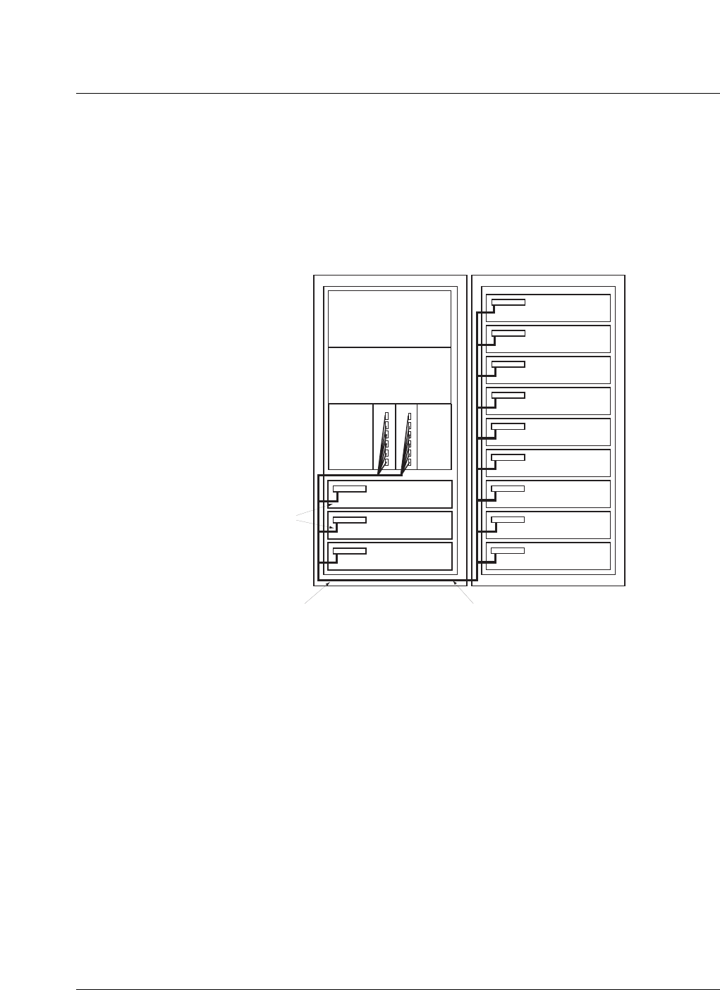
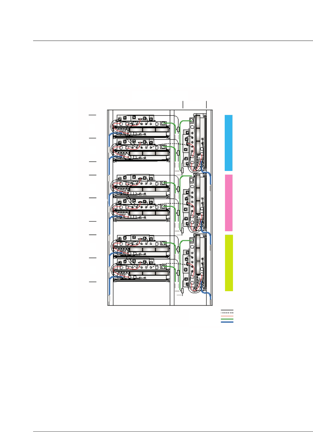
Cables are routed from the Radio Rack (RR) to the Digital Rack (DR) via a
fiber cable routing tube and / or channel located at the bottom of the DR bay.
The optical link scenario is illustrated in Figure 7, Figure 8 and Figure 9.
Figure 7
Indoor EOM to CORE optical link cable routing DR/RR collocated
FRM
FRM
FRM
FRM
FRM
FRM
FRM
FRM
FRM
EOM
EOM
FRM
FRM
FRM
EOM
CORE A CORE B
Digital Rack Radio Rack
Fibre cable bay transition
tube / channel
One Fiber Cable Assy type required for each
installed FRM. A maximum of 12 cables
required for full capacity
Fiber Management
Bracket (1 per FRM)
Introduction to Metro Cell 11
CDMA Metro Cell Functional Description Manual NBSS7.1
Figure 8
FRM optical link cable routing
12 Introduction to Metro Cell
411-2133-110 Prototype 01.04 November 1998
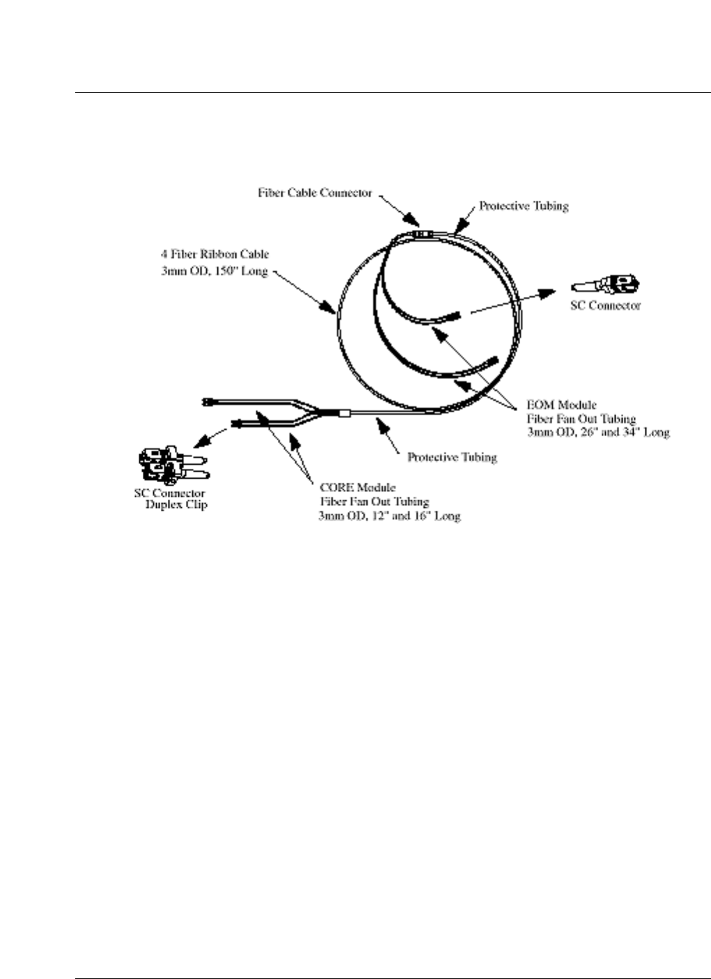
Figure 9
EOM to CORE fiber cable assembly
The RR accommodates up to nine FRM modules, each of which supports the
RF air interface for a single CDMA sector. FRM module frequency
assignments are defined on a per module basis, so a fully populated RR could
support an additional three carriers/three sectors or some other combination
up to nine sectors. Thus, a two cabinets indoor Metro Cell support 4 carriers/3
sector configuration. Six-sector configuration can be supported through the 2
racks.
Digital equipment architecture
The Digital Enclosure (DE/DEI) system consists of a Digital Enclosure
Interface (DEI), digital shelf, fan tray, heater, heat exchangers, and a power
shelf in an outdoor enclosure. The digital shelf is one large shelf sectioned off
in two areas, the top shelf and the bottom shelf. There is a shared back plane
that covers the top portion of the bottom shelf and the bottom portion of the
top shelf. The CEM, CM, CORE and GPS modules are housed together in a
digital shelf.
A graphical drawing of a digital shelf is shown in Figure 10.
Introduction to Metro Cell 13
CDMA Metro Cell Functional Description Manual NBSS7.1
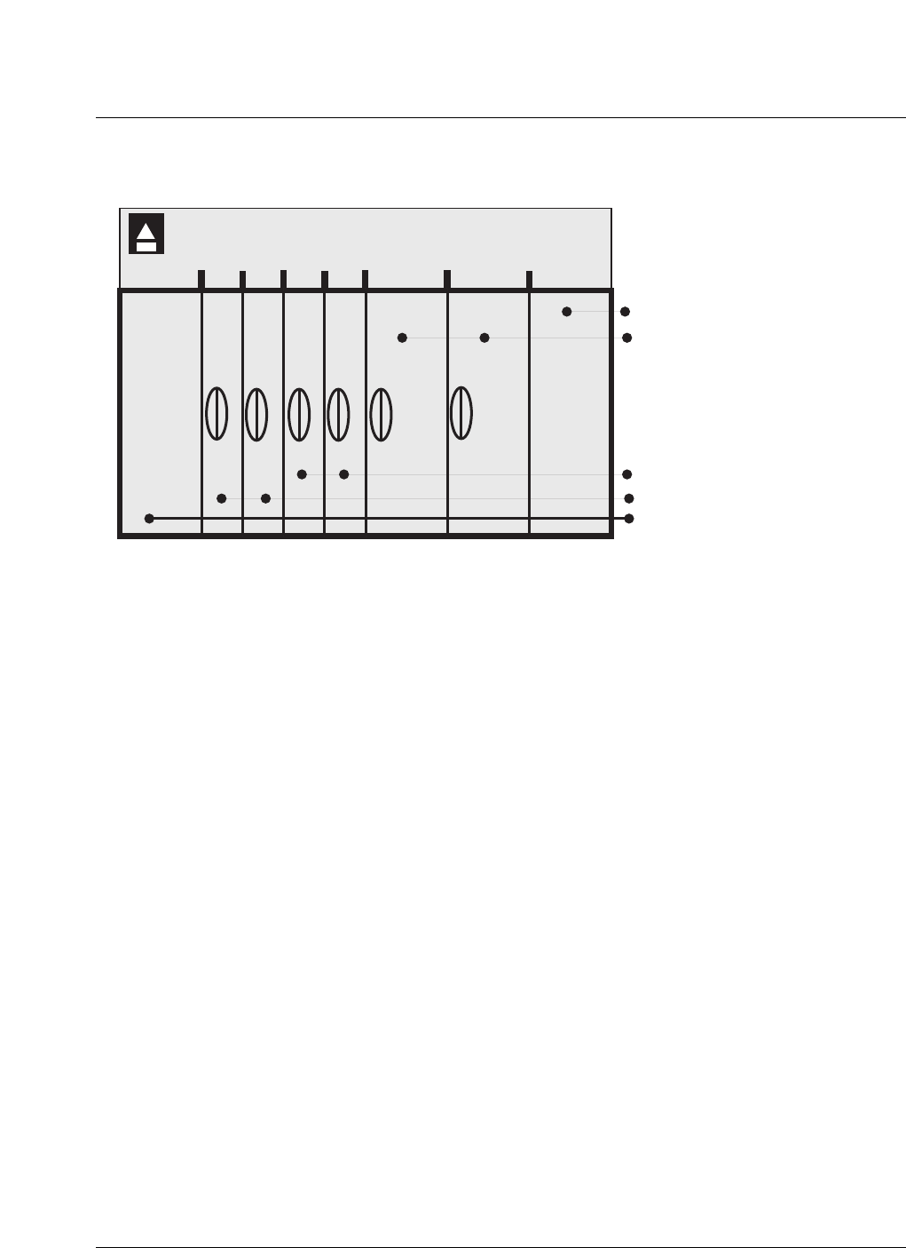
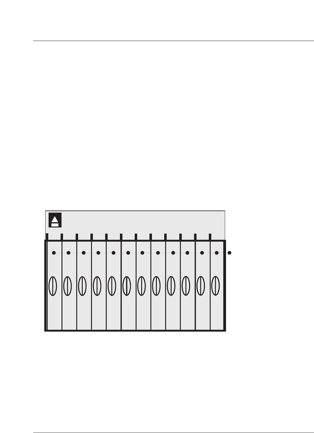
Figure 10
Digital shelf (bottom) graphic
The top shelf contains the Channel Element Modules.
The Digital Equipment shelf houses the following modules:
• Channel Element Modules (CEM)
The following is a list of features provided by the channel cards (up to two in
the CEM) and the module as a whole.
• face plate LEDs indicate the status of the module.
• diagnostic port to aid in software debugging and local downloads.
• parity checking of forward and reverse paths, to detect faulty ASICs or
paths.
• disabling of faulty channel card, ASICs or paths.
• capture of reset failures.
• low voltage detection/reset on channel cards.
• channel card originated reset to the other Channel Card.
• low speed Inter-Integrated Circuit (IIC) bus.
• fault monitoring of IIC bus.
• fault monitoring of the other channel card in the module if present.
— fault monitoring of registers ability to write.
A horizontal partition allows for inserting up to 12 CEMs on the top side and
the CORE, Control and GPS modules on the bottom side.
12345
678
Power Alarm Interconnect
CORE: COnfiguration
REsource Modules
CM: Control Modules
GPSTM: GPS Timing Modules
T1 Interconnect

14 Introduction to Metro Cell
411-2133-110 Prototype 01.04 November 1998
All modules plug in to a common backplane
DC power is supplied via the backplane.
Cable interconnect (optical fiber) is through the CORE front module
faceplates.
Environmental control
Thermal design
Outdoor cabinet
The MetroDE is intended for use in unprotected outside environments and, as
such, must be able to withstand a wide range of temperature and humidity
conditions. The enclosure includes a control system to manage and reduce
the environmental extremes seen by the electronics.
The primary components of the thermal control system are:
• The Enhanced Controller Module within the Helios System 3500/48
power shelf
• The internal cooling unit (lower fan tray)
• The 120 Vac tubular heater assembly
• The heat exchanger
• The internal and external heat exchanger fan trays
The Enhanced Controller Module is interfaced to all of the other thermal
control system equipment and, along with its primary duties within the power
system, executes an environmental monitoring and control algorithm. It reads
temperatures from two separate redundant temperature sensors, humidity
from a relative humidity sensor, and fan failure signals from each of the
separate fans. From this information and the values of various factory
adjustable thermal parameters, the ECM operates the fans and heater in order
to minimize temperature and humidity fluctuations within the cabinet.
The internal cooling unit sits at the very bottom of the DE cabinet and forces
air up through the equipment stack to ensure that generated heat is carried
away from the equipment. This tray consists of four fans that are constantly
running at full speed. Since they are not controlled in any way, the only
interface to the thermal control system is a single alarm wire that indicates
whether any of the four fans has stopped rotating. The cooling unit also
houses the humidity sensor, and the cooling unit power/fault status LEDs.
The AC heater assembly is directly above the cooling tray and provides heat
to the enclosure for cold start and cold weather operation. It is under the
direct control of the ECM and includes two failsafes: an overtemperature
cutout to ensure that the heater cannot be enabled above 50 degrees Celsius,

Introduction to Metro Cell 15
CDMA Metro Cell Functional Description Manual NBSS7.1
and a wiring arrangement that ensures that the heater cannot be enabled if
there is no power to the cooling tray fans.
The heat exchanger is located at the very top of the cabinet behind the
external loop fan tray and allows heat from internal air to be transferred to
external ambient air while keeping dust, salt and moisture outside of the
cabinet.
The heat flow through the heat exchanger is controlled by the internal and
external loop heat exchanger fan trays. The internal fan tray consists of two
fans that force cabinet air past the inside surfaces of the heat exchanger, and
the external fan tray consists of three fans that force external ambient air past
the external surfaces. Each fan is separately controlled by the ECM. By
enabling a variable number of these fans, the air flow, and hence the heat flow,
through the exchanger core can be manipulated to regulate the temperature
within the cabinet.
In addition to the two fans, the internal heat exchanger fan tray also contains
the power switching electronics for the fans, the undertemperature fan
cutouts, and the fan power/fault status LEDs.
The relative humidity within the cabinet is indirectly controlled by altering
the cabinet temperature setpoint. If the humidity gets too high, the internal
temperature is raised to the point where the humidity drops to acceptable
levels, subject to a preset maximum.
A physical layout of the thermal system components is shown in Figure 11.

16 Introduction to Metro Cell
411-2133-110 Prototype 01.04 November 1998
Figure 11
Outdoor Metro Cell layout of thermal control system components
External loop heat exchanger fan tray Heat exchanger
(behind)
Internal loop heat exchanger
fan tray
Digital
enclosure
(door open)
Helios power
shelf 1
E
C
M
Heater Assembly
Internal Cooling Tray

Introduction to Metro Cell 17
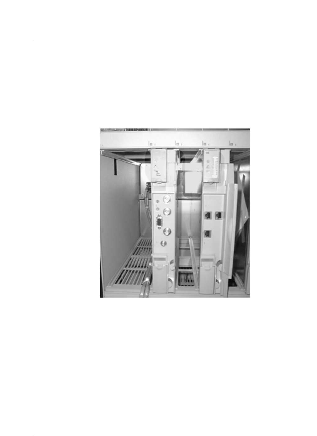
CDMA Metro Cell Functional Description Manual NBSS7.1
Indoor digital rack (DR) of the Metro Cell
The Power Supply System can be ac or dc. In the ac version, the top two
shelves are equipped with ac to dc rectifiers. The shelf also contains breaker
panel for the dc distribution to the various modules and supply feed to the
batteries for recharging.
Up to 3 FRMs are housed in the DR.
Figure 12 shows an equipped DR.
Figure 12
Digital rack
Indoor cabinet thermal management
Thermal management in the Digital Rack is provided by a single cooling unit
with 5 fans below the DE shelf providing bottom up cooling for the Digital
Shelf, and Rectifier Shelves. Thermal management for the FRMs in the DR is
done at the FRM module.
18 Introduction to Metro Cell
411-2133-110 Prototype 01.04 November 1998
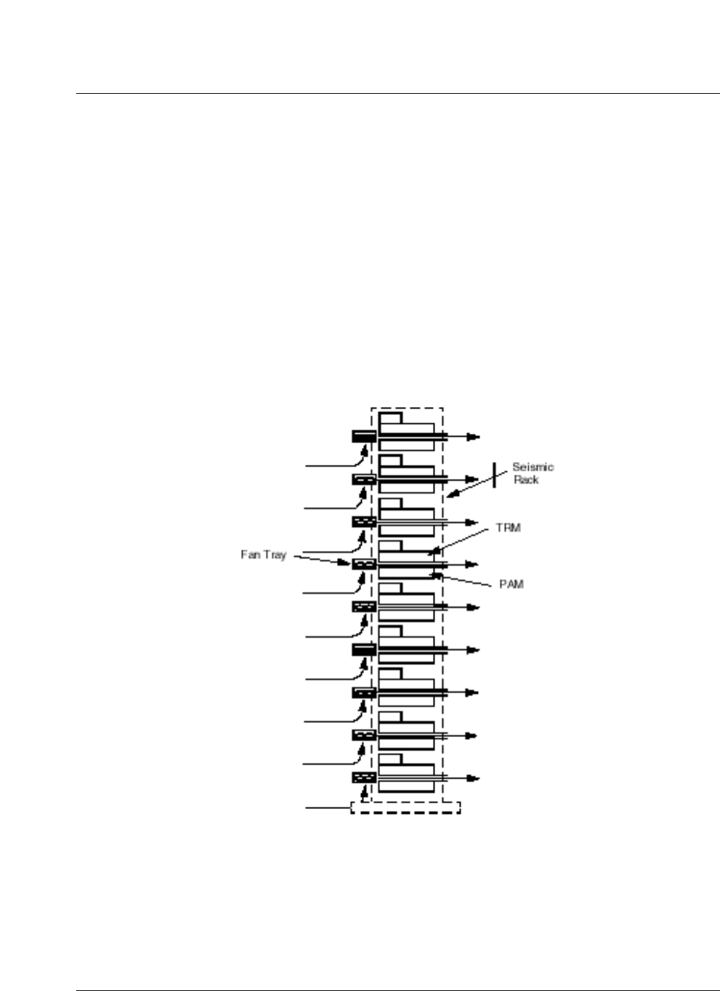
As all thermal control for FRMs is done at the FRM module level, the Radio
Rack itself has no thermal requirements other than the sufficient air flow
through the FRM by providing a minimum 6 inches from the rear wall.
Air flow in the Radio Rack is driven by the FRM fans. FRM fans push air
over the FRM heatsink and out the rear of the rack.
The air flow through each FRM is ducted to prevent recirculation of hot air
inside the RR. The Digital Rack is sealed off in the back to prevent hot air
from the FRM to recirculate into the digital equipment. The fan tray contains
an anti-back flow flap which stops hot air recirculation.
Figure 13
Indoor cabinet airflow

Introduction to Metro Cell 19
CDMA Metro Cell Functional Description Manual NBSS7.1
Outdoor radio enclosure (RE) physical architecture
The Radio Enclosure provides ventilation, solar and vandalism protection and
structural mounting support for the FRMs. All environmental isolation is
done at the Flexible Radio Module (FRM) level.
Optional hardware includes IMF filters and combiners for 800 MHz FRMs
and triplexers for 1900 MHz. FRMs.
Each FRM consists of five field replaceable units (FRUs). They are the
TRansceiver Module (TRM), Power Amplifier Module (PAM), Electro-Optic
Module (EOM), Duplexer Preselector Module (DPM), and Fan and Alarm
Indicator Module (FAM).
Additionally all external alarm interfacing and surge protection is done in the
RE.
Up to 9 FRMs are housed in the RE. The FRMs consist of five Field Replaceable
Units (FRUs)
• Electro-Optics Module (EOM)
— the EOM is located at the FRM side of the High Speed Serial
interconnect.
— contains two optical transceivers for redundancy
— the light source is LED at approximately 1350 nm. No laser eye
protection is required.
• Transmit Receive Module (TRM)
— performs modulation and de-modulation via “channelizer” ASICs.
— performs clock recovery and synthenization.
— performs Digital to Analog and Analog to Digital conversion.
— performs up and down frequency conversion.
— performs power control and power detection.
— allows for limited system overlay ability.
— external alarm routing.
• Power Amplifier Module (PAM)
— provides RF Power Amplification
— interface for DC power from the Digital Enclosure
— provides DC Distribution to other FRM modules.
• Duplexer (DPM) with or without preselector
— two DPMs with or without preselector.

20 Introduction to Metro Cell
411-2133-110 Prototype 01.04 November 1998
— provides RF signal filtering.
— provides threshold extension / receive signal amplification.
— provides Interface to TRM and from PAM.
• Fan and Alarm Module (FAM)
— provides vectored constant velocity airflow for ambient PAM cooling.
— provides fault indications for all five FRUs.
The RE is shown in Figure 14.
Introduction to Metro Cell 21
CDMA Metro Cell Functional Description Manual NBSS7.1
Figure 14
Radio enclosure
(Three Carriers / Sector)
f3
f2
f1
f2
f1
f2
f1 S
e
c
t
o
r
A
l
p
h
a
S
e
c
t
o
r
B
e
t
a
S
e
c
t
o
r
G
a
m
m
a
RF
RF (expansion path)
Data power
Fiber
Power

22 Introduction to Metro Cell
411-2133-110 Prototype 01.04 November 1998
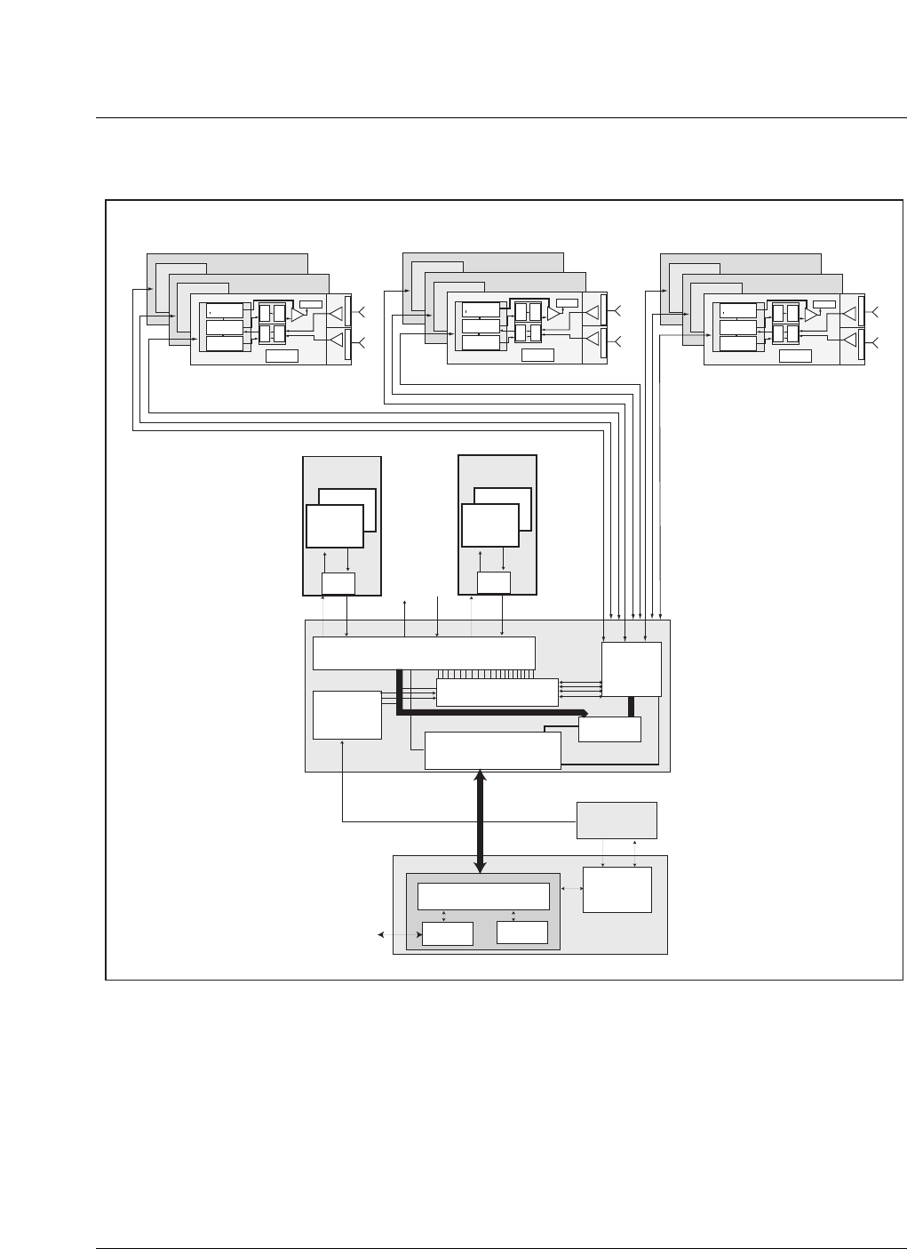
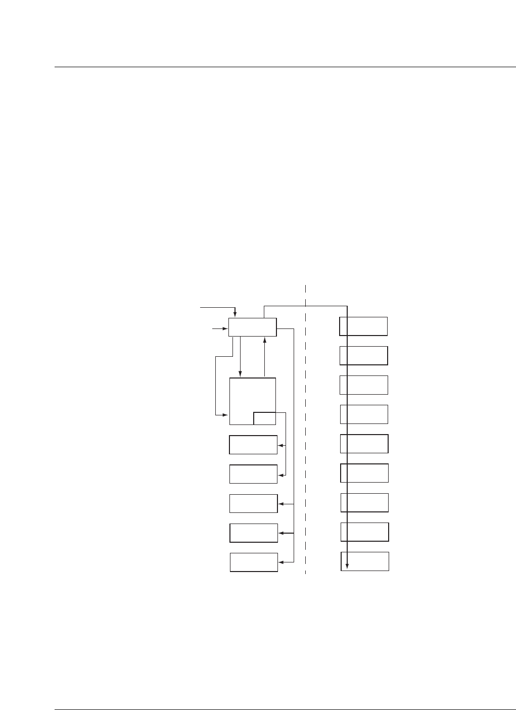
Module interrelationships
Figure 15 shows the relationship between the different modules making up
the Metro Cell. This depicts a three carrier configuration. Up to 12 CEMs can
be provisioned. Each CEM may have 24 or 48 channel elements.
The CORE module provides the interface between the CEM and the FRMs.
Essentially, the CORE is responsible for the switching, routing, addition and
multiplexing of baseband data signals between the CEMs and the FRMs.
The GPS module is the source of timing and frequency reference. The GPS
directly provides the reference signals to the CORE and CM.
Introduction to Metro Cell 23
CDMA Metro Cell Functional Description Manual NBSS7.1
Figure 15
Module relationships
I/F
CEM Interface
CORE MODULE
Freq &
timing
reference
Signal Distribution
& Consolidation
RFM
Optical
Interface
CORE
Controller
Multiplexer
24
ASICs
CEM
I/F
24
ASICs
CEM
6 BCN
1 BCN
24 BCN
32 BCN
GPSTM
Module
BTSC
Router
(BCN DISCO Functionality)
T1/E1 micro
processor Control Module
BTSI
RF Power
Detector
PA
D
u
p
l
e
x
e
r
P
r
e
s
e
l
e
c
t
o
r
LNA
LNA
UP
Conv
Down
Conv
Tx
Chann-
elizer
Rx
Chann-
elizer
DC Power Supply
u Controller
Optical I/F
Frequency
Ref. Recovery
FRM α f 3
FRM α f 2
FRM α f 1
RF Power
Detector
PA
D
u
p
l
e
x
e
r
P
r
e
s
e
l
e
c
t
o
r
LNA
LNA
UP
Conv
Down
Conv
Tx
Chann-
elizer
Rx
Chann-
elizer
DC Power Supply
u Controller
Optical I/F
Frequency
Ref. Recovery
FRM β f 3
FRM β f 2
FRM β f 1
RF Power
Detector
PA
D
u
p
l
e
x
e
r
P
r
e
s
e
l
e
c
t
o
r
LNA
LNA
UP
Conv
Down
Conv
Tx
Chann-
elizer
Rx
Chann-
elizer
DC Power Supply
u Controller
Optical I/F
Frequency
Ref. Recovery
FRM γ f 3
FRM γ f 2
FRM γ f 1

24 Introduction to Metro Cell
411-2133-110 Prototype 01.04 November 1998
25
CDMA Metro Cell Functional Description Manual NBSS7.1
2Subsystem description
Outdoor Metro Cell power systems
DEI physical layout
The location of the major components in the DEI is shown in Figure 16.
Many of the PP&G cables from the DE and Helios 3500/48 terminate in the
DEI. The connections to the Helios shelf pass through the access hole in the
back of the DEI.
Figure 16
Layout of components in DEI
Cable entry and exit
BIM
compartment
for battery
string #1
-48 Vdc
connects
DC
protectors
battery
return
reference
plate
GPS protector
behind
optical fiber
connect box
fiber cables
access
hole
DE
ac
cables
ac power distribution
ac breakers generator
inlet
T1 prot. T1 prot. I/O prot.
outlet ac prot.
2

26 Subsystem description
411-2133-110 Prototype 01.04 November 1998
The following external interfaces and terminations are provided in the DEI:
• Utility 208/240 Vac power entry: 4-wire cable to ac panel (L1, L2, N &
PE).
• AC generator: recessed 4-pin power receptacle, with access door.
• AC power to cabinet heaters: ac cables to DE and EBC.
• DC outputs to FRMs: Qty 9, 2-wire plus shield terminals, two-hole crimp
lugs.
• T1 backhaul lines: Qty 6, screw-down terminals at protection modules.
• GPS Antenna: Qty 2, N-type coax connector on protection unit.
• DC power bus: -48V power cables to the EBC batteries.
• Battery monitor (BIM): RS485 serial link from EBC (if used).
• External inputs/outputs: Qty 12, alarm/control lines at protection module
(if needed).
• Ground (to MetroRE): two-hole lug termination on BRR plate.
Backhaul interface
The Metro Cell terminates up to 6 T1/E1 ports and is software programmable
in order to select between the T1 or E1 protocols. It supports B8ZS, AMI line
coding for T1. HDB3 line coding for E1, SF and ESF framing is supported.
The Metro Cell can be daisy chained to other BTSs up to a total of 3 BTSs in
the chain. Each BTS must be assigned at least 4 contiguous DSOs over the
backhaul link. The total T1/E1 connections supported by a Metro Cell is 6
which includes connections coming into the Metro Cell through two cables at
the DEI. These cables can have any number of T1s/fractional maximum of 3
T1s/fractional T1s going out to the other BTS.
Surge protection
All external electrical interfaces are protected against surges and transients
from lightening strikes. This includes all interfaces in the DEI and the power
and RF connections at the FRMs.
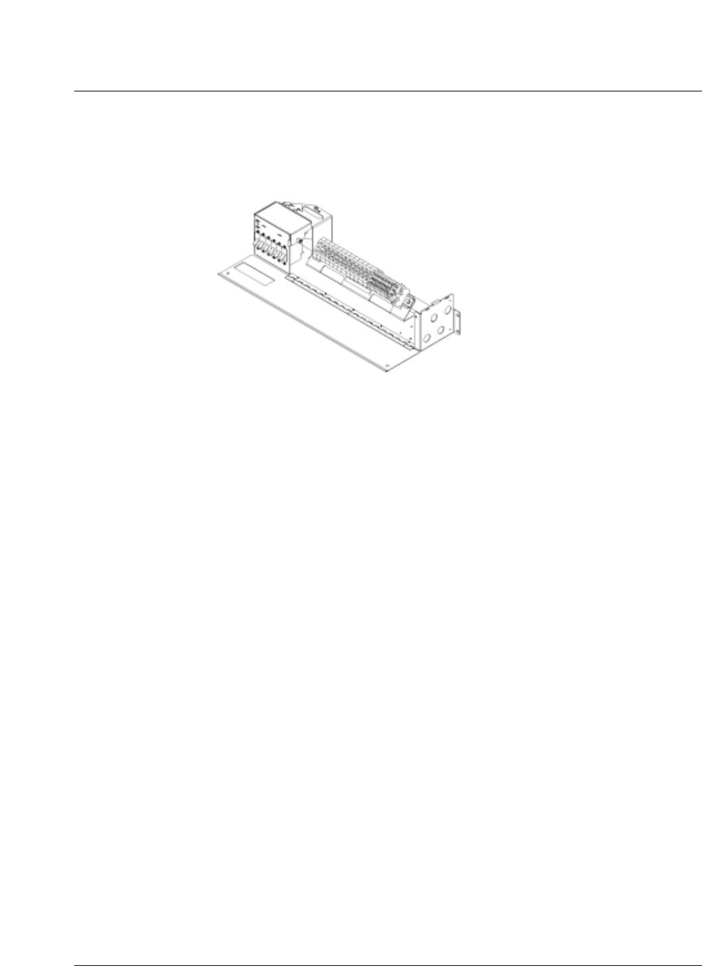
AC power entry and distribution
The ac power system has the following components:
• service entrance for permanent connection to the utility ac power source.
• facility for connecting an external ac generator for emergency backup use,
with a positive interlock to prevent both utility and generator being
connected at the same time.
• indicator display to show that ac power is available and from which
source.
2

Subsystem description 27
CDMA Metro Cell Functional Description Manual NBSS7.1
• overcurrent protection (circuit breakers) and lightning surge arrestors at
the ac power entry.
• circuit breakers in various sizes to service and protect the internal ac load
circuits.
• the Metro Cell ac loads include the following: ac-dc rectifiers
• cabinet heaters
• 120Vac, 15 Amp duplex convenience outlet.
A power panel is shown in Figure 17.
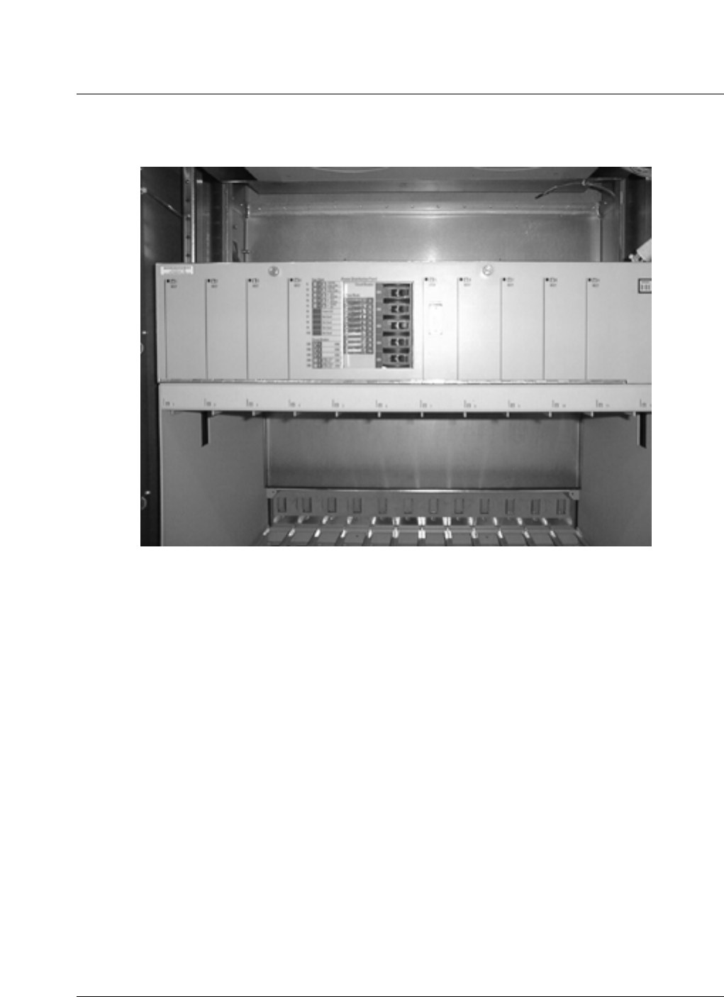
Figure 17
AC circuit breaker panel box in the DEI
DC power and distribution
The Metro Cell dc Power System comprises the following functions:
• AC-DC power conversion via parallel rectifier units.
• charge/discharge management for the backup batteries.
• DC power distribution for the DC loads (internal and external).

28 Subsystem description
411-2133-110 Prototype 01.04 November 1998
• overcurrent protection for DC load circuits (breakers).
• filtering of power interfaces against EMI and transients.
• monitoring and alarms for the power system.
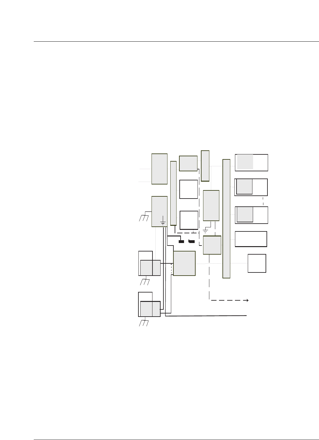
Power, protection and grounding architecture
The Metro Cell is powered by a combined ac and -48 Vdc power system.
Figure 18 shows a simplified block diagram of the major items comprising
the outdoor Metro Cell power, protection and grounding architecture. The
principal ac power, dc power and grounding interfaces are also identified.
AC power is provided either through the utility connection or by an external
generator. DC power is derived from the ac by rectifiers and stored in battery
strings. Circuit breakers provide over current protection and fault isolation for
both ac and dc circuits. The ac powers the cabinet heaters. The dc powers the
environmental control units for the system. DC to dc converters provide
electronic loads with isolated and regulated dc power at the required voltages.
Signal and power cables are protected against transients and surges at every
external interface. All cabinets, circuit modules and cable shields are properly
grounded for safety. Power system operation is monitored and controlled
internally and external alarms are set in the event of specified faults or failure
events.
Batteries are located in the DEI or in a separate, expansion cabinet, depending
on the configuration chosen. Each battery location is designed to facilitate the
safe installation, inspection, or removal of the batteries in a minimum amount
of time by one person. The terminals of each battery incorporate a protective
cover to prevent accidental contact by maintenance personnel.
The battery enclosures have louvers to vent any gasses produced by the
batteries to the outside air, such that buildup of a flammable or explosive
hydrogen gas mixture cannot occur. Battery gasses are not able to enter the
main system enclosure.
Backup batteries and sensors
The backup batteries used in the Metro Cell are sealed lead-acid, 12 Vdc
(nominal) batteries intended for long life, maintenance free, stationary, UPS
type applications. Four series batteries comprise one -48Vdc string.
Additional parallel strings in an optional external battery cabinet may be
added for extended backup time .
Under normal operating conditions, the batteries are float charged to 100%
capacity at a constant voltage by the ac-dc rectifiers. The ECC (Enhanced
Controller Card) located in the rectifier shelf, controls the float voltage,
monitors battery charging a discharging, monitors the individual battery
string temperature and adjusts the load voltage so that the batteries can be
fully charged without danger of excessive gassing. Thermistor temperature
Subsystem description 29
CDMA Metro Cell Functional Description Manual NBSS7.1
sensing on the terminals of each battery string is provided to interface with
the ECC.
The ECC also monitors the midpoint voltage of each battery string to
determine if the batteries in that string are charging equally and whether any
battery cells are weak. The ECC also maintains a record of recent charging/
discharging events which can be accessed by the serial data link as a battery
health report to assess the health of each battery string and project their
remaining capacity and life.
Figure 18
Power protection and grounding block diagram
The Digital Enclosure Interface (DEI) on one side of the main cabinet is used
for all external interfaces.
The dc power subsystem includes the new Helios Mini 48 power system.
These include rectifier modules, battery management and alarm functions and
a dc distribution/breaker panel in one small shelf. A second rectifier shelf is
provisionable for adding extra power capacity.
With these components, the power system architecture is modular and quite
flexible and can be adapted to multiple carriers and a wide range of electronic
module (FRM and CEM) configurations.
dc - dc
converters
ac entry
and
protection
main
ground
plate
A
C
b
r
e
a
k
e
r
s
ac - dc
rectifiers
cabinet
heaters
other
ac loads
battery
strings
ECC &
alarms
dc power
exit and
protection
D
C
b
r
e
a
k
e
r
s
CES
modules
CEM
CEM
Heat exchanger
and fans
other
dc loads
dc - dc
converter
dc - dc
converter
FRM
FRM
dc - dc
converter
dc - dc
converter
P
E
M
P
E
M
B
r
e
a
k
e
r
s
ac line
ac generator
earth
cabinet frame
cables
status and alarms
digital enclosure grounds
note : shaded blocks are the power, protection and grounding items
-48Vdc
BRR
30 Subsystem description
411-2133-110 Prototype 01.04 November 1998
Figure 19
Metro Cell power and grounding interconnections
Indoor Metro Cell power systems
The Indoor Metro Cell power system is similar to the outdoor version. There
are three options for powering the Indoor Metro Cell. These options are:
• AC Mains Operation
• -48Vdc Operation
• +24Vdc Operation
AC power Input
In the AC input version, the Metro Cell will operate in similar fashion as
described above for the outdoor Metro Cell. AC breakering for the input must
be provided by the customer.
The external AC power enters the Metro Cell through the bulkhead at the top
of the digital rack. The AC power is provided by 240Vac, 3 conductor (L1, L2
and ground) power feeds.
Figure 20 shows the AC power architecture.
AC line
FRM
FRM
FRM
DC cables
T1/E1 comm.
ground
Digital Enclosure Interface
and short term batteries
Radio
Enclosure
DC power distribution
Rectifiers
Rectifiers
ECC
ECC
C
E
M
C
E
M
C
E
M
CORE, CM and GPS

Subsystem description 31
CDMA Metro Cell Functional Description Manual NBSS7.1
Figure 20
Indoor AC power architecture
Figure 21 shows the AC System bulkhead.
Bulkhead
AC in
Customer batteries
Digital Rack Radio Rack
FRM
FRM
FRM
FRM
FRM
FRM
FRM
FRM
FRM
FRM
FRM
FRM
AC DC
Battery
Breakers
Opt. Rectifier
breakers/fuses
breakers/fuses
Digital Shelf
Fan Tray
Rectifier
32 Subsystem description
411-2133-110 Prototype 01.04 November 1998
Figure 21
AC system bulkhead
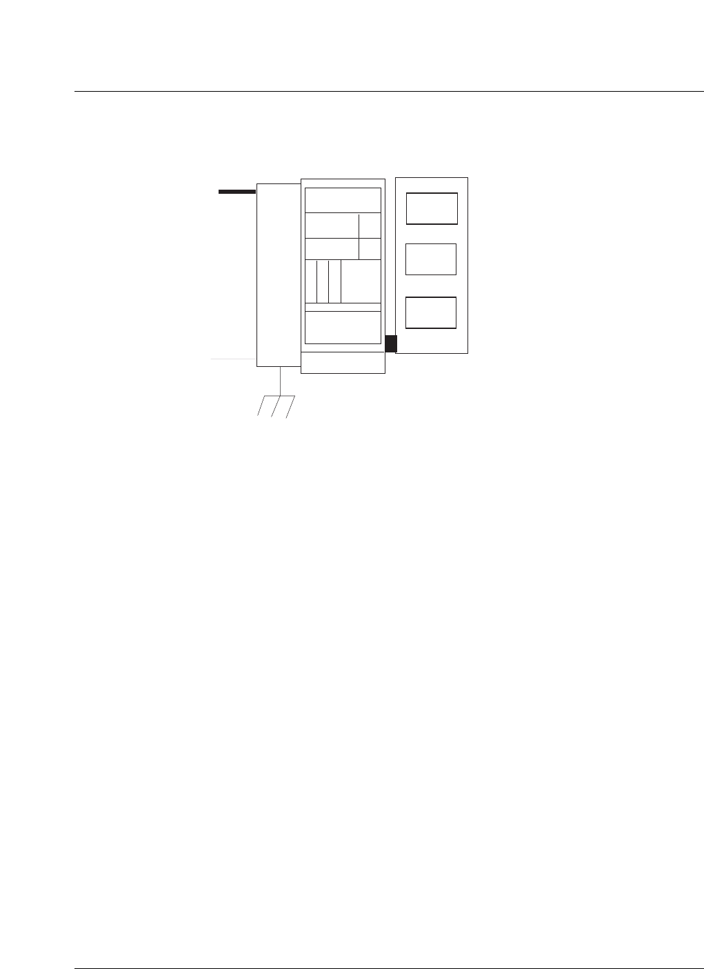
Figure 22 shows the A/C Indoor Metro Cell Packaging; indicating the AC
System bulkhead and the rectifier shelves. It is to be noted that a maximum of
2 rectifier shelves can be provided; with a total of 16 rectifiers.
T1/E1
(RJ48H
amphenol)
A/C Input
(208/240 Vac,
L1, L2, Gnd)
Battery
Switches
(100 AMP
Breaker)
D/C Output
to FRM’s
GPS
Antenna
(N Conn.)
A/C Output
to Rectifiers
Subsystem description 33
CDMA Metro Cell Functional Description Manual NBSS7.1
Figure 22
Indoor ac Metro Cell packaging
The AC to DC rectifiers are located in the rectifier shelf at the top of the DR.
The rectifier shelf is a Helios 3500AC Power Shelf. Each shelf can
accommodate 8 rectifiers, in a N+1 configuration. The rectifier shelf also
contains an ECM and breakers as described above in the outdoor
configuration.
DC power input
The Metro Cell is powered by -48Vdc input supplied by the customer. The
DC feed enters at the bulkhead in the DR. The DC breaker panel provides the
DC distribution to the digital shelf, fans and the FRMs. The FRMs in the RR
are fed through the bulkhead as supplied by the breakers in the DC breaker
panel.
DC power distribution (FRMs)
The indoor Metro Cell provides for the -48Vdc supply required by the FRMs.
The DR bulkhead has 12 Vdc FRM power outputs connection. Up to six
34 Subsystem description
411-2133-110 Prototype 01.04 November 1998
breakers are provided in the dc breaker panel. Each breakered FRM power
output is split into two FRM power feeds in the DR bulkhead.
Power is supplied to the digital shelf backplane via four separate feeds. The -
48 Vdc is kept separated on the digital shelf backplane and supplies the
modules (CEM, CORE, CM and GPSTM) via hot pluggable connectors on
the backplane.
Figure 23 shows a block diagram of the Indoor Metro Cell dc power
architecture.
Figure 23
Indoor dc power architecture
The indoor system dc bulkhead is shown in Figure 24.
Bulkhead
DC in
Digital Rack Radio Rack
FRM
FRM
FRM
FRM
FRM
FRM
FRM
FRM
FRM
FRM
FRM
FRM
DC DC
Digital Shelf
Fan Tray
ECC
breaker/fuses
DC Breaker
Panel
Subsystem description 35
CDMA Metro Cell Functional Description Manual NBSS7.1
Figure 24
Indoor system dc bulkhead
Indoor and outdoor Metro Cell distribution module
The Mini-48 system has up to eight 500W rectifier plugs in modules in a single
shelf, with their own control module. Each rectifier converts the AC power to
filtered -48Vdc (nominal) dc power for the Metro Cell battery and loads. These
modules optionally operate in an N+1 redundancy mode to supply continuous
loads up to 3500 watts. The rectifier modules perform the following functions :
• convert ac power into the nominal -48Vdc voltage level for the Metro
Cell.
• provide the necessary charging and float voltage requirements for the
batteries.
• prevent EMI emissions on both the ac and dc side.
• provide parallel operation with current sharing.
• provide N+1 optional operation and hot plug/replace capability.
• provide front panel operation status indicators.
• are fully connectorized for quick service via unit replacement in the field.
The rectifier shelf also houses the the Enhanced Controller Module (ECM).
The ECM implements the dc power system and monitoring functions. It also
performs the following functions:
• controls the current sharing among the rectifier modules.
• monitors rectifier performance and report it to the Metro Cell CM on
demand.
• generates minor and major alarms for dc power system failures.
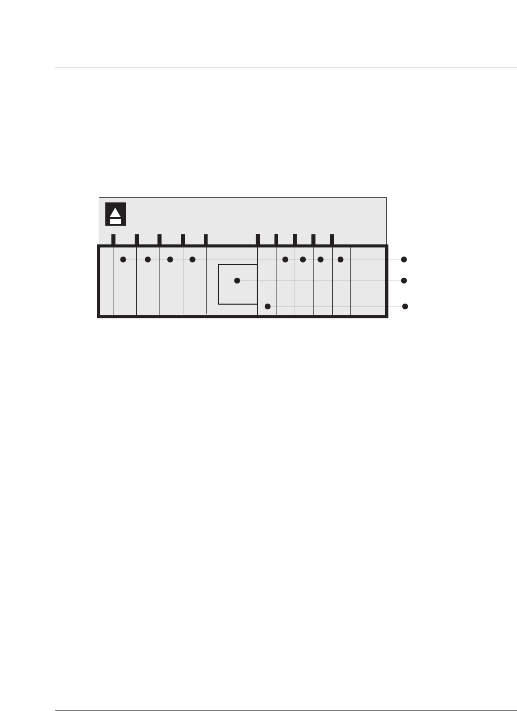
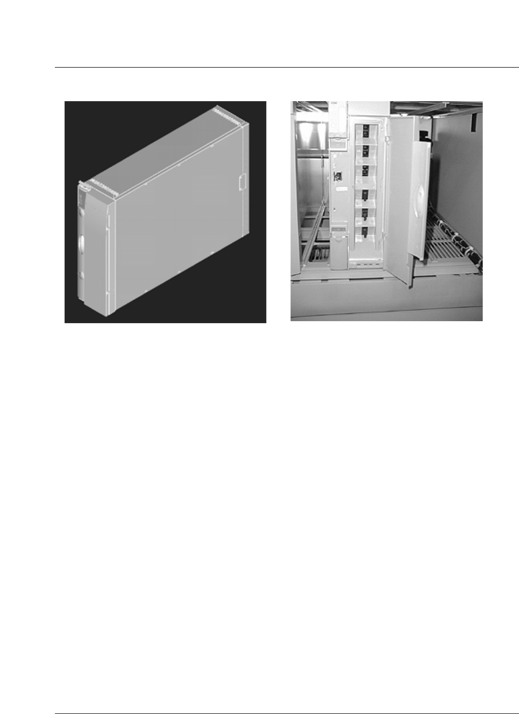
36 Subsystem description
411-2133-110 Prototype 01.04 November 1998
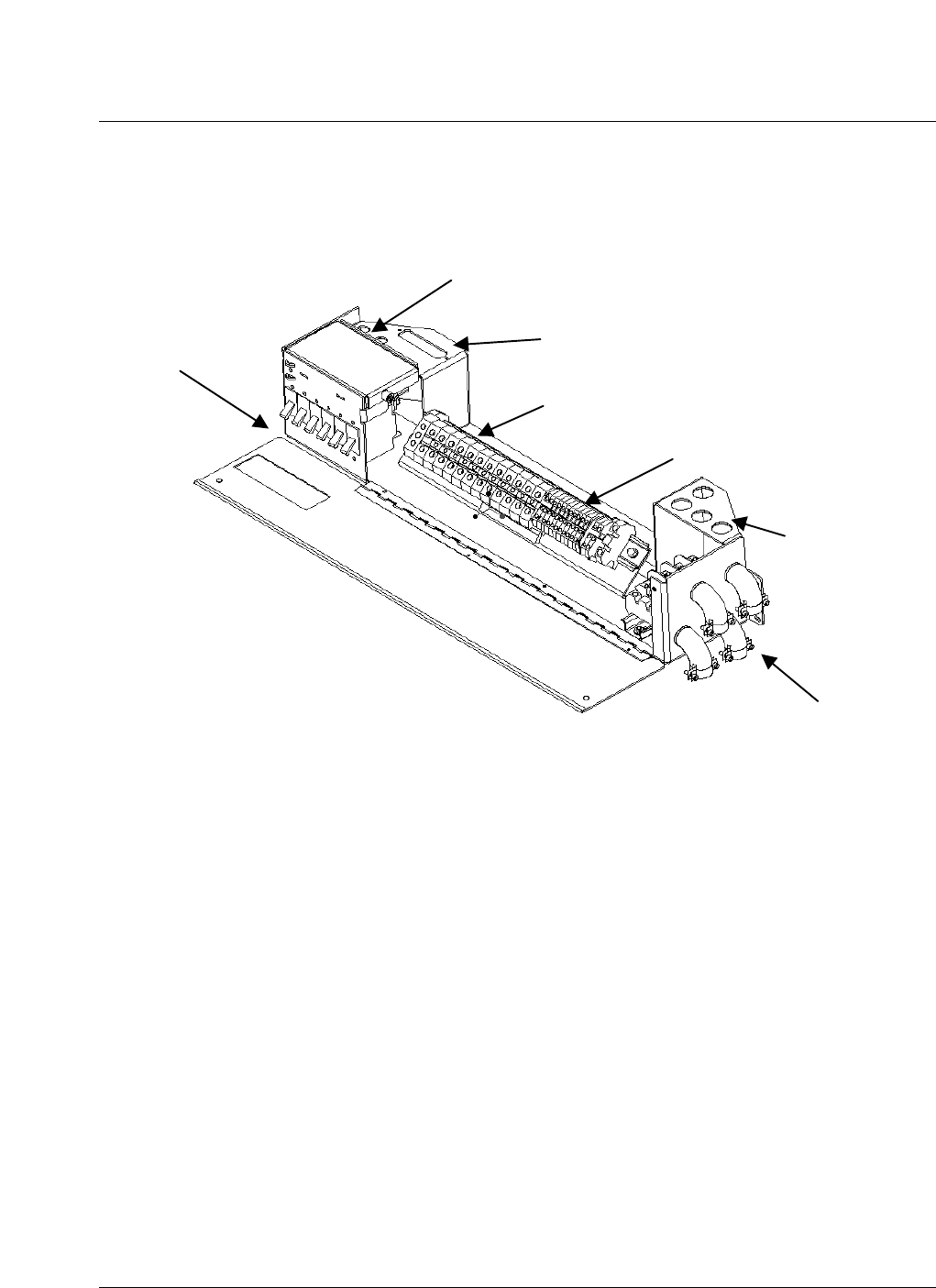
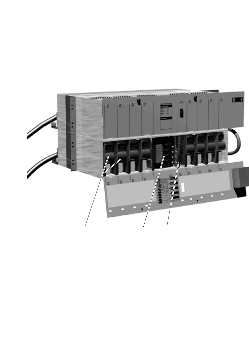
A graphic of a rectifier shelf is shown in Figure 25, a photograph of a closed
rectifier shelf is shown in Figure 26 and a photograph of an open rectifier
shelf is shown in Figure 27.
Figure 25
Power shelf (graphic)
1234 56789
Ctlr: Controller Module
DC Power Distribution
P
Rect: Rectifier Modules
38 Subsystem description
411-2133-110 Prototype 01.04 November 1998
Figure 27
Open rectifier shelf
Rectifiers Breakers ECM

Subsystem description 39
CDMA Metro Cell Functional Description Manual NBSS7.1
The breaker sticker on the rectifier shelf is shown in Figure 28.
Figure 28
Breaker sticker
Battery management
The enhanced controller module (ECM) provides the control and monitoring
functions for the dc power subsystem. One of its principal responsibilities is
to manage the charging and discharging of the backup batteries. When ac
power is restored, following an outage, any excess current available from the
rectifiers is applied to recharge the batteries. These are charged up to a
controlled float voltage, and once recharged are maintained at that level. The
float voltage is adjusted for battery temperature.
The ECM also incorporates the following features for managing the batteries:
• temperature compensation of the float voltage for the selected battery
type.
• Low Voltage Disconnect (LVD) to shut off the loads when the batteries
are discharged below 42 Vdc. This protects the batteries from deep
discharge and permanent damage.
• Over Voltage Protection (OVP): rectifier output voltage does not exceed
the battery manufacturer’s recommendation for continuous float charging
(around 56V) to prevent excessive battery gassing which could shorten
the battery life and represent a safety hazard.
• Over Temperature Shutdown: shutdown the rectifiers at high battery
temperature conditions, with automatic restart upon falling below this
temperature. Shut down temperature is selectable to comply with the
battery specifications.

40 Subsystem description
411-2133-110 Prototype 01.04 November 1998
• Battery Health Monitor: monitor the battery strings and provide charging
history, performance data, life data, etc. Report health status and any
weak/shorted cells via a serial data link to the Controller Module.
Power distribution
This Mini-48 function includes the circuit breakers and terminations to
distribute the -48Vdc power to the batteries and the dc loads. The circuit
breakers used for dc distribution are magnetic-operation, UL listed types and
incorporate provisions for each dc breaker to report the presence of a tripped
condition to the controller. Power wiring in each circuit is of sufficient gauge
to conduct the rated current of the circuit breaker for that circuit with minimal
voltage drop within or between the BTS cabinets.
Disconnect facilities are provided to disconnect (in conjunction with the
Enhanced Controller Module) the batteries and the rectifiers from the loads
under the following conditions:
• dc voltage falls below 42.0 volts.
• all dc system loads are supplied from the nominal -48 Vdc battery rail.
This provides no break dc power to the following loads:
• the RF and digital equipment.
• the GPS receive.
• the FRMs (external to the electronics cabinet, whether remote or local).
• the battery monitoring card (Enhanced Controller Module) subsystem.
• the environmental control fans.
Subsystem description 41
CDMA Metro Cell Functional Description Manual NBSS7.1
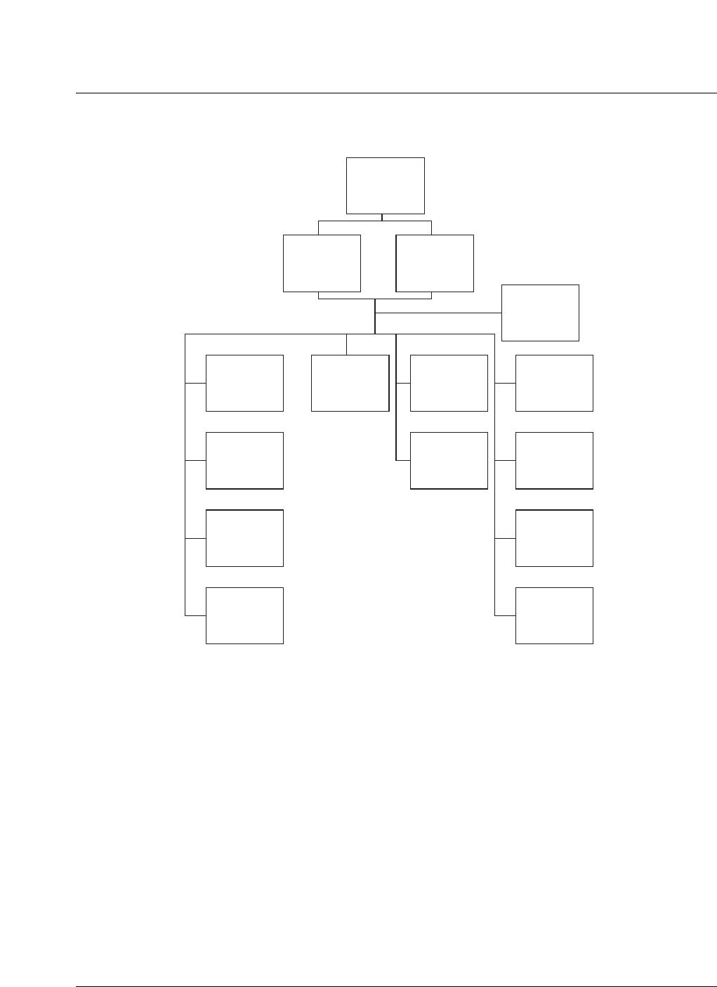
Figure 29
Power distribution block diagram
NT6C34EA-61
Helios Mini
System 3500/48
NT5C22DA
System Shelf
NT5C22DA
System Shelf
(Optional)
NT5C15AA
250 W Rect.
Conv. Cool
Fan Shelf
NT5C15BB
500 W Rect.
Conv. Cool
NT5C15BC
500 W Rect.
Forced Cool
NT5C15AA
250 W Rect
Conv. Cool
Front Doors
NT6C34DE
Distribution
e/w LVD
NT6C34DF
Distribution
e/w BLVD
NT6C34CA
Standard
Controller
NT7C25AA
Enhanced
Generic
NT7C25PC
Slave
Enhanced
NT7C25XX
Enhanced
MCBTS
42 Subsystem description
411-2133-110 Prototype 01.04 November 1998
Grounding
For personnel safety and correct functioning of protection devices, proper
grounding (both internal and external) of the Metro Cell system is essential.
The main grounding plate in the interface module provides a central bonding
point for all system grounds. This is connected to a good quality external site
ground, and ties all the internal grounds and references together electrically.
The ground plate also provides termination for external ac and RFM power
cable grounds and coaxial cable shields. The cabinet frame and all conductive
external surfaces are also grounded to the same plate.
The secondary side (Logic Return) of all dc-dc converters in the modules
shall be grounded to the module frame or chassis which, when installed, shall
be bonded to the frame of the cabinet. In systems with multiple cabinets, each
cabinet frame ground are connected separately to the main ground plate in the
DEI by means of a copper cable.
Battery backup
A backup battery is used to maintain system power during ac power outages.
The Metro Cell is optionally provisioned with one or more strings of 12Vdc
(nominal) lead acid batteries to provide backup energy storage.
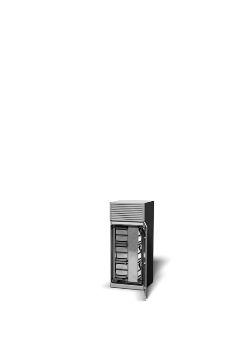
A battery storage frame is shown in Figure 30.
Figure 30
Battery storage frame

Subsystem description 43
CDMA Metro Cell Functional Description Manual NBSS7.1
CEM principle functions
The CEM resides in the Metro Cell Digital Shelf. The primary responsibility
of the module is to process calls within the Metro Cell. To accomplish this
function, it interfaces with the CORE module in order to receive digital
samples and transmit baseband digital data. The CEM also interfaces with the
CORE in order to send and receive traffic and control information. It also
interfaces with the system to send and receive control information associated
with call setup, tear down, and hand-off.
Each Channel Element) on a Channel Card is configured via software to
perform a variety of tasks, including:
• traffic Channel.
• pilot Channel.
• sync Channel.
• paging Channel.
• access Channel.
• OCNS (Orthogonal Channel Noise Simulator).
• some combinations of overhead channels.
The ‘Built In Testing’ (BIT) function is used to perform built-in tests on Channel
Element Hardware, including:
• channel card/Processor interface tests.
• modulator section signature analysis tests.
• DRAM integrity tests.
• JTAG boundary scan.
The CEM can contain one or two channel cards that are connected to an
interconnect board. Each channel card in the CEM can function
independently of the other card in the module. The module is capable of
carrying up to 48 traffic and control channels. The actual number of channels
and their composition is determined by software.
In a module equipped with two channel cards, one channel card is capable of
powering the interconnect board and operating on its own if the other fails.
The redundancy in this type of configuration is viewed as a “loss of capacity”
strategy. As a module, the two channel cards monitor each other over an Inter-
Integrated Circuit (IIC) bus; and, in the event of failure on one of the channel
cards, the other one assumes control of the Interconnect board and informs
the system that it has done so.
The module is built in an EMI shielded container which does not interact with
the other CEMs in the shelf except through software. The Interconnect board
inside the module interfaces to the CORE module via a 639 Mb/s serial link.
44 Subsystem description
411-2133-110 Prototype 01.04 November 1998
Module LEDs indicate the status of the module as a whole (refer to Metro
Cell Maintenance and Troubleshooting Guide, 411-2133-550).The LEDs can
indicate that the module is faulty or that one of the boards is still in working
order and can carry on servicing users. Module software informs the system
of the status of the internals of the module by monitoring status signal
throughout the channel cards.
The CEM contains 24 or 48 Channel Elements (CE) on one or two channel
cards, CEM Interface circuitry, serial/parallel converters and a power supply.
The CEM can be connected to two separate COREs as part of the optional
redundancy strategy.
There is a maximum of 4 X 48 CEMs per sector.
A graphic of a Digital Equipment Shelf showing the CEMs is shown in Figure
31.
Figure 31
Digital equipment shelf (top) graphic
Power and the Tx/Rx baseband are distributed on a simple shielded
backplane.A fully populated CEM shelf is shown in Figure 32.
12345678910
11 12
CEM: Channel Element
Modules
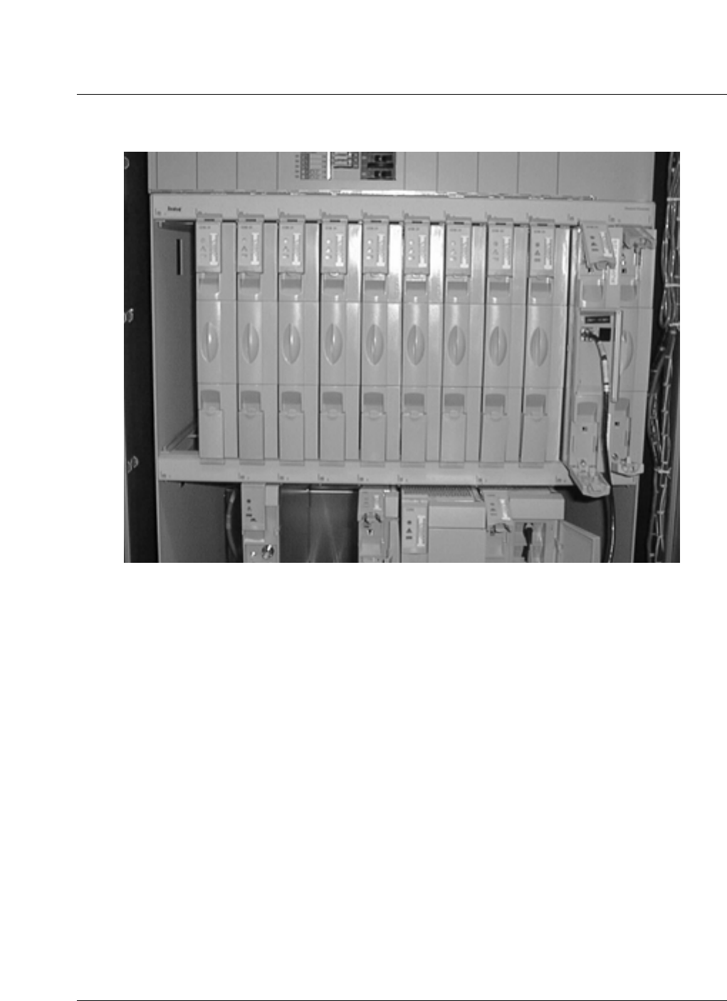
Subsystem description 45
CDMA Metro Cell Functional Description Manual NBSS7.1
Figure 32
CEM shelf
46 Subsystem description
411-2133-110 Prototype 01.04 November 1998
Figure 33
CEM diagram
Forward and
Reverse path
Baseband modems
Power
Module
Summing
FPGA
I 960
Processor
and
Memory
USC
BCN / FPD
Control /
Status IIC
L
E
D
S
Reverse path
Chain 1
Chain 2
I960
bus
Forward and
Reverse path
Baseband modems
Power
Module
Summing
FPGA
I 960
Processor
and
Memory
USC
BCN / FPD
Control /
Status IIC
L
E
D
S
Reverse path
Chain 1
Chain 2
I960
bus
Reverse path Baseband
Mux /
Demux
High Speed
Link to CORE
CORE
Interface
BCN
IIC
CHANNEL CARDS INTERCONNECT BOARD

Subsystem description 47
CDMA Metro Cell Functional Description Manual NBSS7.1
CEM Interconnect board (IB)
The CEM IB provides the interface between the two channel cards and the
CEM and CORE Modules.
On the Forward Path the IB sums the two Channel Cards CDMA forward link
Baseband and multiplexes it with the reverse link BCN traffic from the
Channel cards.
On the Reverse Path the IB demultiplexes the 650 Mbps serial data from the
CORE and splits it into CDMA forward link BCN data and CDMA reverse
link baseband data.
CEM dc voltages
Each Channel Card Module is powered from the -48 Vdc power rail
accessible along the back of the CEM shelf. Each CEM has an internal Power
Supply to convert this to the regulated supply voltage(s) needed by the
channel cards and other circuitry. The channel cards require a +5 Vdc supply.
Each CEM has two Channel Cards and Interface cards, for a total power of
less than 100W at -48Vdc.
Timing and frequency systems
Global positioning system timing module (GPSTM)
The GPSTM is an oscillator which provides outputs of 8fc (9.8304 MHz), 1/2
Hz (even second), 10 MHz and serial data. The primary clock signals are
distributed directly to the CM and CORE over the back plane. The CORE
distributes the clock signals to the FRMs and CEMs over the high speed serial
link.
The GPSTM also supplies the system with the time of day obtained though a
serial interface to the CM.
An internal oscillator stabilizes / tracks to GPS system time. The receive
frequency is 1575.42 MHz.The GPSTM is a GPS disciplined oscillator which
provides outputs of even_second, 10 MHz, 9.8304 MHz and serial data
The GPSTM also provides 10 MHz, 8fc and 1/2 Hz out for test equipment
synchronization. Signals are available at the front of the card via a push on
connector.
A 24 hour holdover after a 24 hour training period is provided as well.
The CORE and CM monitor the quality of the primary clock signals and
report any deviations from normal operation.

48 Subsystem description
411-2133-110 Prototype 01.04 November 1998
Secondary clock sources PLLs in the CEMs and FRMs re-generate the clocks
as required in these modules for local use. The PLLs are synchronized to the
primary clocks distributed on the high speed serial links.
The timing distribution is shown in Figure 34.
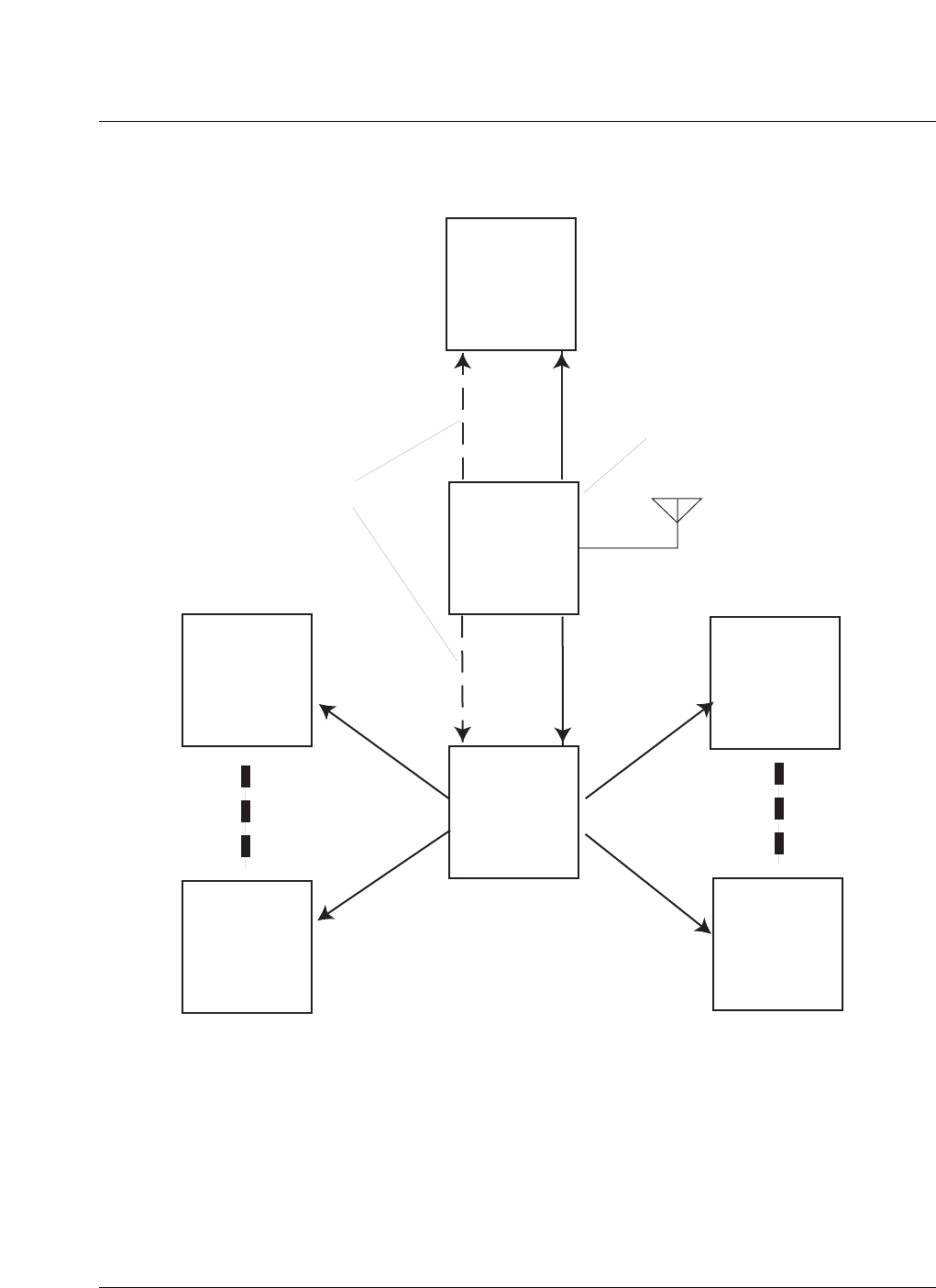
Subsystem description 49
CDMA Metro Cell Functional Description Manual NBSS7.1
Figure 34
Timing distribution
CM
GPSTM
CEM 1
CEM n
CORE
FRM 1
FRM n
High Speed
Serial Link
High Speed
Serial Link
High Speed
Serial Link
High Speed
Serial Link
Primary
Clock
Source
Primary
Clocks
sys
clk
sys
clk
even
sec
even
sec
50 Subsystem description
411-2133-110 Prototype 01.04 November 1998
Antennas
Gps antennas
Two type N connections are supplied in the DEI for the GPS antennas (one
per GPS receiver). Provision is made for grounding the GPS antenna cable to
the ground plate within the DEI.
The GPS card is shown in Figure 35 with a control module (CM) card.
Figure 35
Global positioning system timing module (GPSTM)
Control Module (CM)
The Control module consists of the Base Transceiver Station Controller
BTSC card and Base Transceiver Interface (BTSI) cards. The CM terminates
6 backhaul T1 links which provide drop and insert, and daisy chaining
capability.
The Controller Module (CM) provides BTS control, the backhaul interface,
and the internal BCN network switching and routing.
The CM controls the GPS Module using an asynchronous RS-422 serial port.
One CM can control up to 2 GPS modules .
The BTSI utilizes an embedded processor to control/monitor the T1/E1 ports,
to emulate the CSU interface, and to perform card level maintenance and
diagnostics. In addition the BTSI provides the BCN interface to both the
BTSC and the CORE modules.

Subsystem description 51
CDMA Metro Cell Functional Description Manual NBSS7.1
Control Module BTSC
The BTSC is a new design based upon the Jumbo Universal Controller Card
and provides control and maintenance in the Metro Cell.
The CM BTSC conveys call processing and OA&M messages to the BTSI via
a BCN link. It also receives and controls frequency reference and timing
information (for the Metro Cell) from the GPS Module.
Control Module BTSI
The BTSI terminates 6 T1 / E1 ports and terminates a BCN link transferring
call processing and OAandM messaging to and from the BTSC card. It also
terminates a BCN interface to the BTSI card in the redundant CM. This
interface allows messaging and maintenance to be passed between the BSC
and an inactive BTSC through the BTSI cards.
The Control Module BTSI provides the packet interface to the BTSC in both
the same and redundant CM Modules, the BTSI in the redundant, and the
CEMs and FRMs via the COREs.
Card level maintenance and diagnostics are performed.
CDMA traffic systems
CORE The CORE Module provides the interface between the Control Module,
Channel Element Modules and Flexable Radio modules receiving timing
reference signals from the GPSTM . It accommodates six FRMs and performs
baseband routing, BCN packet Mux and Demux functions, and timing
reference distribution. Essentially, the CORE performs the routing, addition,
and multiplexing of signals between the CEMs and FRMs.
The CORE module can be flexibly programmed to support many different
system configurations.
The CORE consists of:
• performs some of the funcitons of the Legacy Tranceiver Controller Card.
• generates 52fc and 32fc clocking for the Metro Cell
• distributes TDM link data to applicable Channel Card (CEM)
• interface for all High Speed Serial Protocol Control (HSSPC) links.
• performs CEM summing.
• routing of CEM data to applicable frequency and sector.
• routing of FRM frequency and sector data to CEM.
• optical transceiver module is the physical entity of the CORE which
handles the electrical to optical conversion and the optical communication
with the FRMs.

52 Subsystem description
411-2133-110 Prototype 01.04 November 1998
• for each CORE Module there is one optical block which connects to 12
fibres that provide the multi-channel bi-directional data communication
required to connect to 6 FRMs.
• the optical block consists of a serial transceiver, optical receiver, and
optical transmitter.
A CORE module is shown in Figure 36.
Subsystem description 53
CDMA Metro Cell Functional Description Manual NBSS7.1
Figure 36
NTGS30AA CORE module and CORE module with open faceplate
54 Subsystem description
411-2133-110 Prototype 01.04 November 1998
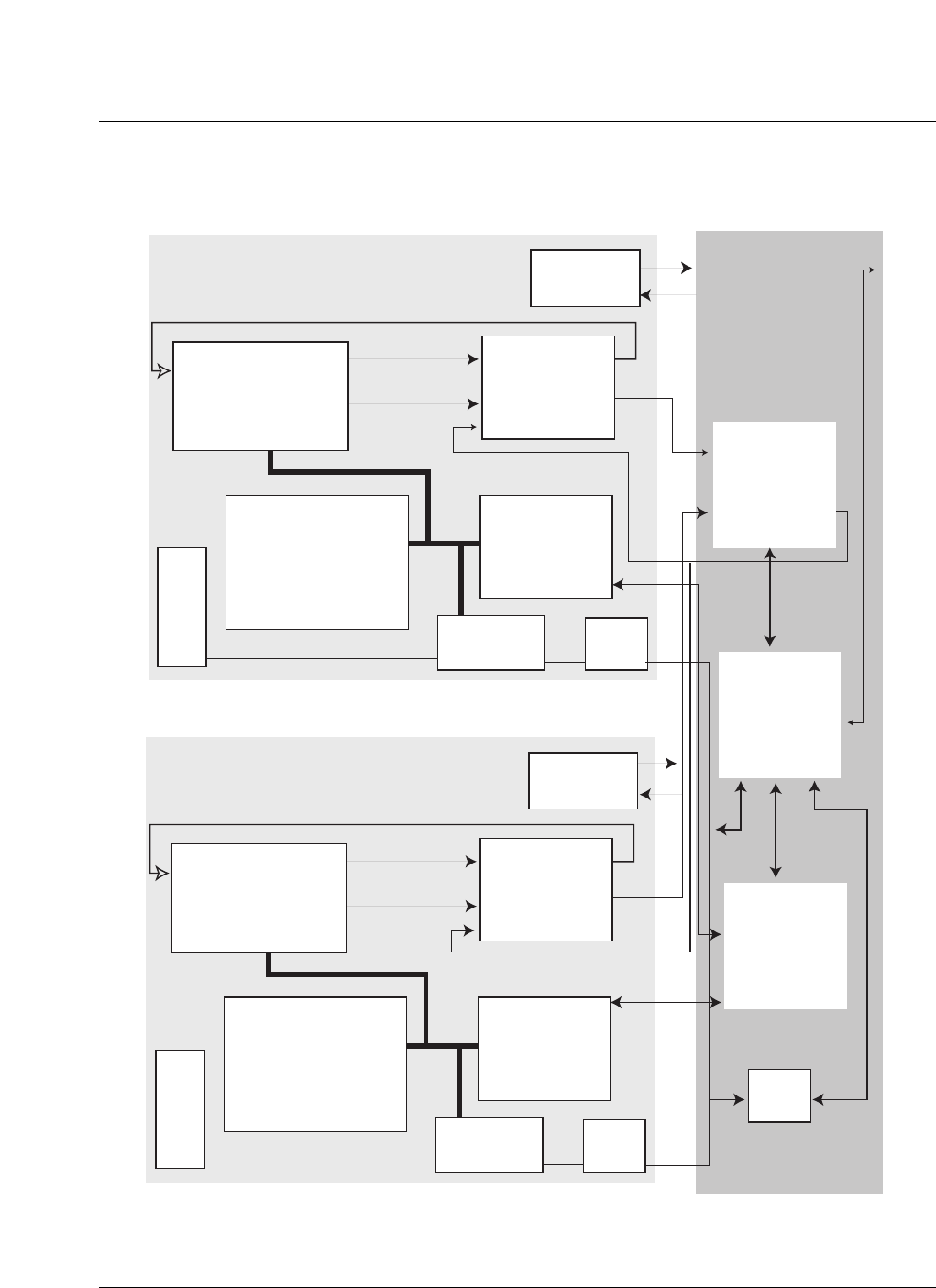
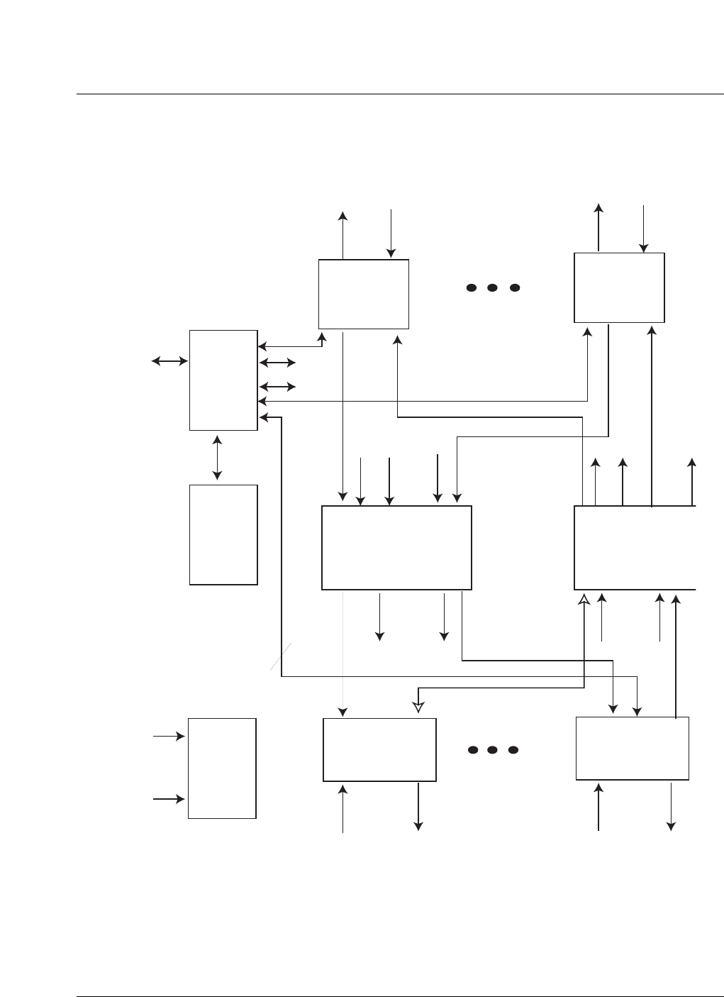
The block diagram of a CORE is shown in Figure 37.
Figure 37
CORE block diagram
BCN
from / to
CM
MUX /
DEMUX
TDM
link
MUX /
DEMUX
BCN
micro
processor Tx baseband
digital switching
and summing
Rx baseband
digital switchin
g
GPS
I/F
Optical
I/F
Optical
I/F
From
GPS 0
From
GPS 1
Optical connections for up to 6 FRMs
Interconnects for up to 12
CEMs
1 BCN
2 BCN / CEM
6 BCN

Subsystem description 55
CDMA Metro Cell Functional Description Manual NBSS7.1
Required optics for operation and/or redundancy
• 1 Carrier 3 sector = 6 fibers no redundancy - 12 fibers for redundancy
• 2 Carrier 3 sector = 12 fibers no redundancy - 24 fibers for redundancy.
• 3 Carrier 3 sector = 18 fibers no redundancy - no redundancy available
with this configuration.
BSC distribution consolodation (DISCO) port allocation
• a 1-carrier Metro Cell requires 1 to 2 CIS ports, assuming 1 to 4 CEMs are
provisioned.
• a 2 - carrier Metro Cell requires 1 to 4 ports, assuming 2 to 8 CEMs are
provisioned.
• a 3 - carrier Metro Cell requires 2 to 6 ports, assuming 3 to 12 CEMs are
provisioned.
Note: Note: A 3 - carrier Metro Cell requires at least 2 CIS ports. This is
due to the fact that at the present time both DCGs must be active to
support 3 carriers, and each DCG has its own pool of T1s.
Flexible RF modules (FRM)
An FRM is shown in Figure 38.

56 Subsystem description
411-2133-110 Prototype 01.04 November 1998
Figure 38
Flexible RF module
HPA
TRM DPM
EOM
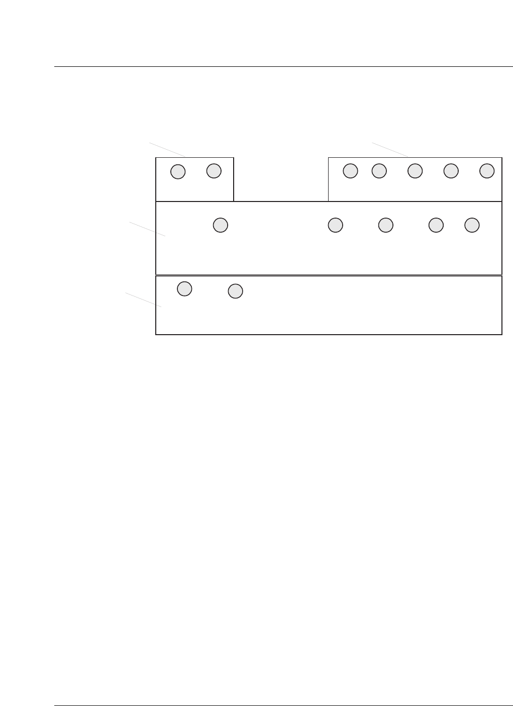
Subsystem description 57
CDMA Metro Cell Functional Description Manual NBSS7.1
Figure 39
Layout of FRM connectors
Each FRM can support one CDMA carrier on one sector. However, for
compatibility with future multi carrier HPAs, the optical interface is designed
for three carrier operation. With single carrier HPAs, multi-frequency
operation is achieved using multiple FRMs.
Multi-frequency operation necessitates multiple antennas per sector. Multi-
faceted antennas or multiple single facet antennas are to provide this
functionality. A duplexer/LNA module is required for each antenna. Two
carriers in each sector can be supported on a diversity pair of antennas (a
diversity pair per sector is the minimum antenna requirement for any CDMA
system) in each sector.
Within the receiver and upconverter many of the functions (E.G. filtering,
Channelization, AGC) are performed digitally. Hence, the FRM interfaces to
the digital enclosure are digital. The interface is implemented as a high speed
serial digital optical link. The data transmitted over the optical link between
the FRM and the CORE comprises Tx and Rx data , OAandM signalling, and
frequency and timing reference signals.
The micro-controller and associated control circuitry within the FRM
performs configuration, fault monitoring and several real time functions
(mainly concerned with Tx sector power control) for the RF electronics.
Tx
IN Tx
IN
Tx
OUT
Tx
OUT
Rx1
OUT Rx0
OUT Ant
Tx/Rx1 Ant
Rx 0
Rx 1
IN Rx 0
Splitter
Output
Rx 0
Splitter
Output
Rx0
IN
HPA
Output
HPA
Input
Power connectors not shown
Transceiver
Module
High Power
Amplifier
Module (HPA)
Optional IMF
Filter Duplex Power Monitor
Module

58 Subsystem description
411-2133-110 Prototype 01.04 November 1998
The frequency reference recovery circuit recovers a frequency reference
received over the optical interface with sufficient accuracy and low phase
noise to meet ANSI J-STD-008 and IS-95 specifications.
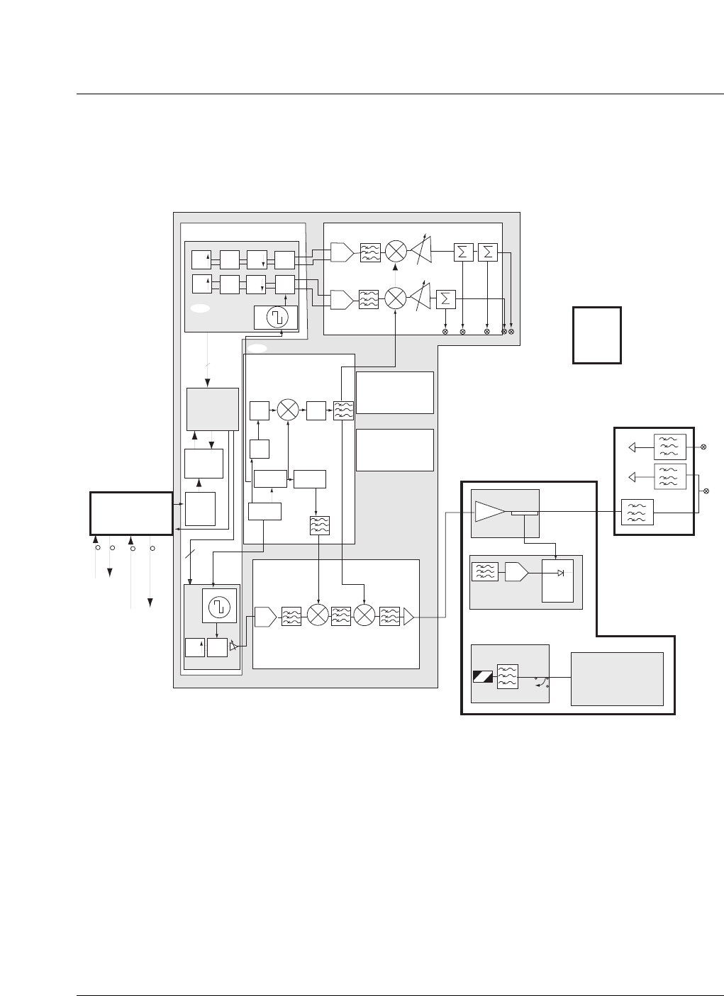
An Flexible Radio Module (FRM) block diagram is shown in Figure 40.
Subsystem description 59
CDMA Metro Cell Functional Description Manual NBSS7.1
Figure 40
Flexible radio module (FRM) block diagram
Depending upon the configuration, the FRM can be made up of some of the
following components:
Transmit / Receive Module (TRM)
— The TRM contains the Transmit/Receive circuitry as well as the
microprocessor board and the attendant power supply. The TRM is
designed as an environmentally hardened module that is cooled using
forced convection.
— The TRM consists of the following circuit packs :
– Power supply module (PSM)
DET
HPA
HIPD Board
PEM PCA
N Bit
48 - 26 Vdc
AIM
AD6600
IF SAW
11 bit
11 bit
Processor Board
PSM
48 -> 3.3D, 5D, 5A
-5D, 8A, 15A
x8/65
/2
DDS x16
x11/8 x11/8
IF LO Upconverter
RF LO
IF SAW
12 bit
AD9762
EOM
Primary
Redundant
FIR
FIR
FIR FIR
FIR
X
X
X
15 @ 32fc
16 @ 32fc
32 fc
RFLO and Clock Recovery
64 fc
HSSPC
ASIC
AMCC
2052
AMCC
3026
AGC
AGC
8fc
Rx Channelizer ASIC
Digital Baseband TRM Receiver
main
diversity
RF LO
DPM
PAM
Tx Channelizer ASIC
121 fc

60 Subsystem description
411-2133-110 Prototype 01.04 November 1998
– Transmit receive module (Transceiver board)
– Microprocessor Board (mP)
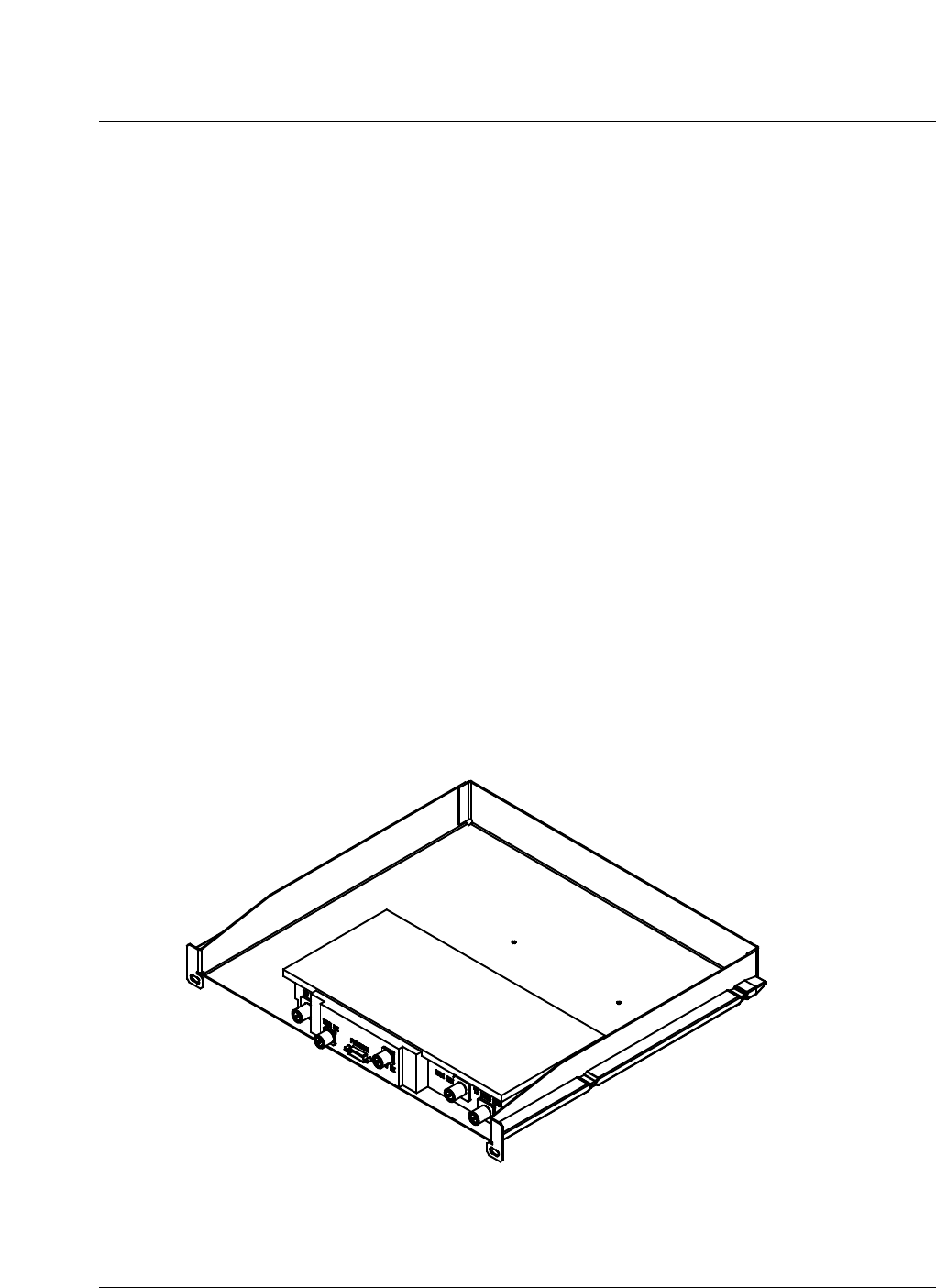
The internal layout of the TRM is shown in Figure 41.
Figure 41
Transmit / receive module internal layout
Duplexer/LNA Preselector/LNA Module (DPM) - 1900 MHz
The duplexer component of the module provides two functions:
— The duplexer provides isolation between the transmit and receive
frequency bands thus facilitating the use of one antenna per diversity
branch per sector.
— The duplexer provides filtering of the transmit and receive
frequencies thus reducing interfering signals.
The LNA component of the module provides a low noise amplification at the
system front end thus reducing the overall effects of noise.
Subsystem description 61
CDMA Metro Cell Functional Description Manual NBSS7.1
The DPM operates within the FRM framework of the BTS system. The DPM
is the last stage in the transmit section of the FRM preceding the antenna and
lightning surge protectors; the FRMDPM is the first stage in the receive
section of the FRM following the antenna and lightning surge protectors.
In the single carrier per sector case, the FRMDPM must include a preselector/
LNA that provides a conditioned antenna diversity signal to the receiver.
Module 1 is comprised of the basic FRMDPM component with a preselector/
LNA. In the multicarrier per sector case, the FRMDPM does not require the
additional preselector/LNA to achieve antenna diversity. Module 2 is
comprised of the basic FRMDPM component without a preselector/LNA.
The 1.9 GHz PCS bandwidth, with respect to the FRMDPM operation, is
subdivided into three bands, therefore three unique FRMDPM specifications
are required. The FRMDPM specification #1 operates in the 1850 - 1870
MHz receive band and in the 1930 - 1950 MHz transmit band. The
FRMDPM specification #2 operates in the 1870 - 1890 MHz receive band and
in the 1950 - 1970 MHz transmit band. The FRMDPM specification #3
operates in the 1890 - 1910 MHz receive band and in the 1970 - 1990 MHz
transmit band. There are three specification requirements for each module
resulting in six different FRMDPM variations.
Figure 42 shows a drawing of a 1900 MHz. DPM.
Figure 42
General DPM drawing - 1900 MHz

62 Subsystem description
411-2133-110 Prototype 01.04 November 1998
Duplexer/LNA module - 800 MHz
The duplexer component of the module provides two functions:
— The duplexer provides isolation between the transmit and receive
frequency bands thus facilitating the use of one antenna per diversity
branch per sector.
— The duplexer provides filtering of the transmit and receive
frequencies thus reducing interfering signals.
The LNA component of the module provides a low noise amplification at the
system front end thus reducing the overall effects of noise.
The 800 DPM operates within the SRFM framework of the 800 MHz CDMA
base station. The 800 DPM is the last stage in the transmit section of the
SRFM preceding the antenna and lightning surge protectors; the 800 DPM is
the first stage in the receive section of the SRFM following the antenna and
lightning surge protectors.
In the single carrier per sector case, the 800 DPM must include a preselector/
LNA that provides a conditioned antenna diversity signal to the receiver.
Module 1 is comprised of the basic 800 DPM800 DPM component with a
preselector/LNA. In the multicarrier per sector case, the 800 DPM does not
require the additional preselector/LNA to achieve antenna diversity. Module
2 is comprised of the basic 800 DPM component without a preselector/LNA.
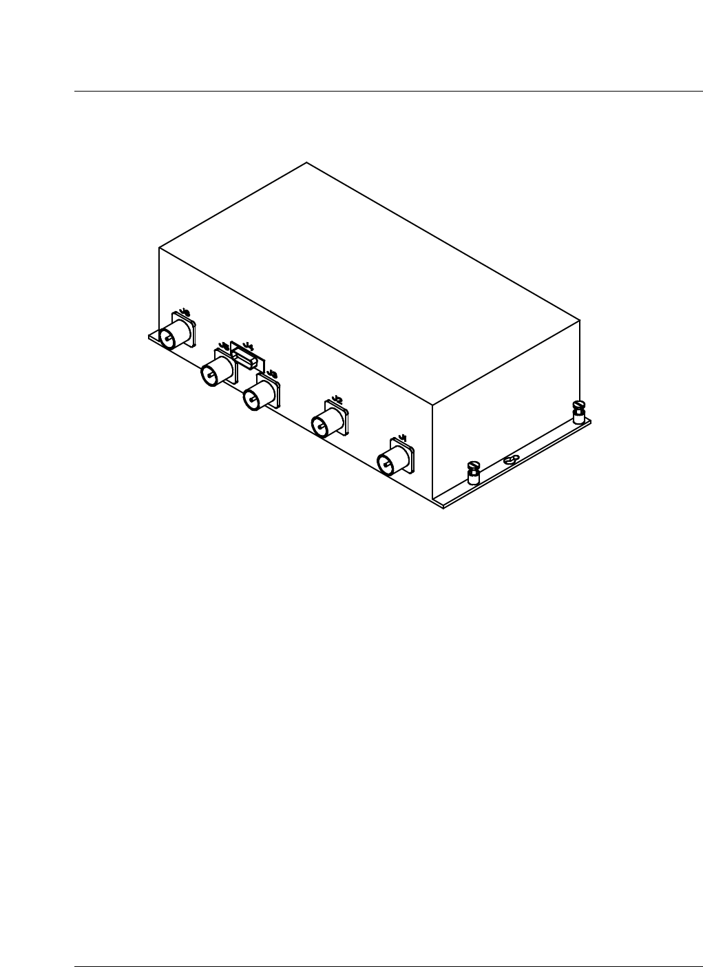
The drawing in Figure 43 illustrates an 800 DPM.
Subsystem description 63
CDMA Metro Cell Functional Description Manual NBSS7.1
Figure 43
General 800 DPM drawing
1900 FRM Triplexer Module (FRMTM)
The Triplexer component of the module provides three functions:
— The Triplexer provides isolation among the transmit signals and
receive signals thus facilitating the use of one antenna for multicarrier
forward link and reverse link.
— The Triplexer provides filtering of the transmit and receive signals
thus reducing interfering signals.
— The Triplexer provides splitting between two received signals.
The LNA component of the module provides a low noise amplification at the
system front end thus reducing the overall effects of noise.
The FRMTM operates within the FRM framework of the BTS system. The
FRMTM is the last stage in the transmit section of the FRM preceding the
antenna and lightning surge protectors; the FRMTM is the first stage in the
receive section of the FRM following the antenna and lightning surge
protectors.
The BTS system has both indoor and outdoor PCS base station using a
CDMA scheme with multicarrier provisions. The base station is intended to
operate in the 1830 - 1990 MHz region. The 1.9 GHz PCS bandwidth, with
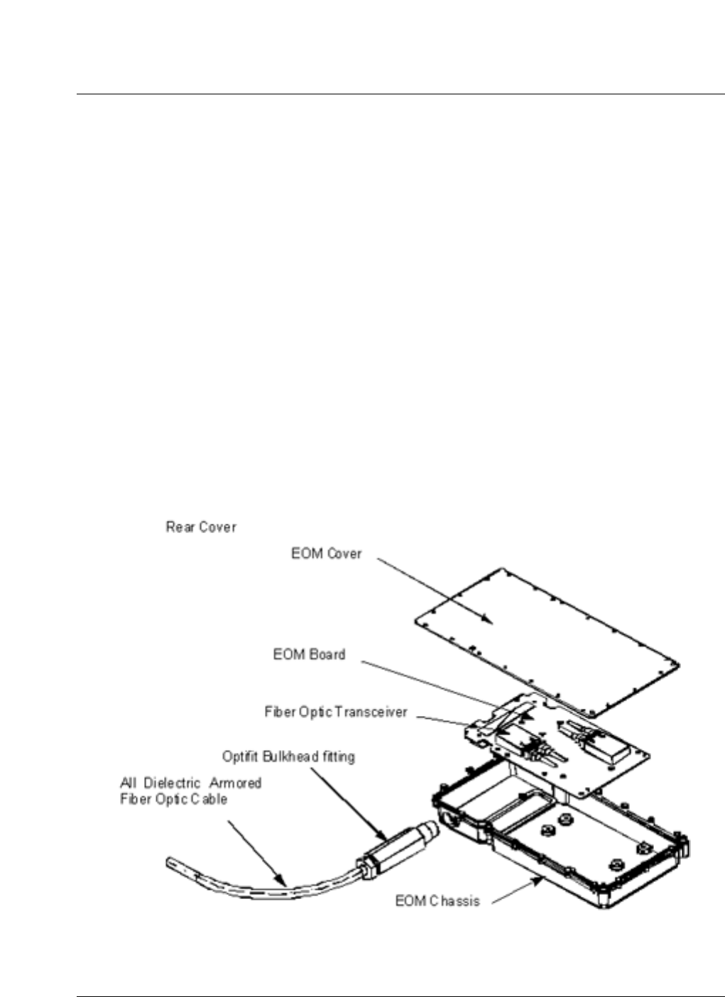
64 Subsystem description
411-2133-110 Prototype 01.04 November 1998
respect to the FRMTM operation, is subdivided into three bands, therefore
three unique FRMTM specifications are required. The FRMTM specification
#1 operates in the 1850 - 1870 MHz receive band and in the 1930 - 1950 MHz
transmit band. The FRMTM specification #2 operates in the 1870 - 1890
MHz receive band and in the 1950 - 1970 MHz transmit band. The FRMTM
specification #3 operates in the 1890 - 1910 MHz receive band and in the
1970 - 1990 MHz transmit band. There are two module design requirements
for each specification resulting in six different FRMTM variations.
Electro-optical Module (EOM)
— The optical fiber will terminate at the FRM electrically. The optical to
electrical conversion is performed in the electro-optical module
attached to the end of the fiber optic cable.
— The EOM contains the circuitry and optical transceivers required to
convert the optical signal from the digital enclosure into an electrical
signal
A diagram of an EOM is shown in Figure 44.
Figure 44
Electro-optical module

Subsystem description 65
CDMA Metro Cell Functional Description Manual NBSS7.1
Power amplifier (PAM)
— The PAM contains the main heat dissipating components of the FRM.
It is designed as an environmentally hardened module that is cooled
using forced convection.
— The PAM consists of the following components :
– power entry module (PEM)
– single channel power amplifier (SCPA)
– power converter assembly (PCA)
–the summary fault alarm from the PCA is a non-latching signal
referenced to +26V_RTN that indicates that the PCA is
operating normally and none of the protection features have
been triggered.
– HPA interface and power detector board (HIPD) which:
–measures the RMS power of the transmitted CDMA signal.
–communicates the measurement to the TRM processor via the
inter-integrated circuit (IIC) bus.
–controls the enable / disable state of the HPA.
–converts the status signals, HPA anxiety, HPA alarm, HPA
fwdpwr, HPA revpwr and HPA temp to digital information to
be transferred to the TRM processor via the IIC bus.
–interfaces with the PCA and reports the status of the alarm to
the TRM processor via the IIC bus.
–allows storage of data within an IIC addressable EEPROM
which is used for manufacturing information and calibration
data for the power detector.
–drives and powers the FAM.
Fan / alarm controller board
A diagram of the internal layout of the PAM is shown in Figure 45.
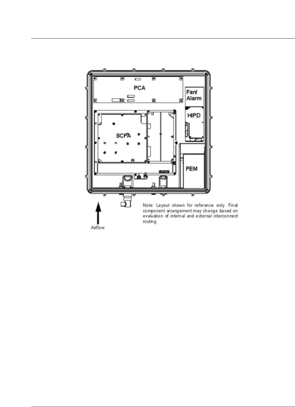
66 Subsystem description
411-2133-110 Prototype 01.04 November 1998
Figure 45
Power amplifier module - internal layout
• Fan tray assembly
• Plenum assembly
• Alarm indicator
A group of 9 alarm indicators are located on an easily visible surface in front
of each FRM as part of the FAM (Fan and Alarm Indicator Module). The
indicators are consistent in size, shape and color with those on the modules
within the DE. The indicator assignments are shown in Table 1:

Subsystem description 67
CDMA Metro Cell Functional Description Manual NBSS7.1
Fault management
FM software detects faults through diagnostic tests, reports the faults with
sufficient information to replace or repair the faulty resource, and map fault
reports into apposite alarms. This ensures high system availability through
rapid fault detection, diagnosis, and recovery from faults.
The functionalities supported by FM include:
• fault Detection and Diagnosis: This includes,
— fault Resolution: Diagnose the location of the faults with enough
precision to correct to problem during operations.
— fault Isolation: Diagnose the location of faults with enough precision
to prevent the fault to damage the rest of the system;
• summarization and Reporting: Report the faults that are detected. If
possible summarize multiple reports into a single report.
• redundancy: A secondary resource is reserved to take over from a failed
primary resource.
• reconfiguration: Automatically reconfigure to use backup/alternate
resources when the operating resource fail.
• recovery: Automatically attempt to recover resources that have failed.
Basestation communication network (BCN) distribution
The internal BTS BCN network is an extension of the BSC BCN network.
The BTS and BSC BCN networks are connected through a T1/E1 link (the
backhaul link).
Table 1
FRM indicator assignments
MODULE GREEN
RECTANGLE RED
TRIANGLE AMBER
CIRCLE COMMENT
PAM x x n
TRM x x n
EOM n n x indicates no
optical carrier
detected
DPM x x n
FAM x x n

68 Subsystem description
411-2133-110 Prototype 01.04 November 1998
The BTSI in the CM passes the T1/E1 link in the internal BCN format. In the
forward direction it routes the BCN packets from the BSC to the appropriate
internal BCN entity over a dedicated link. In the reverse direction it routes
and consolidates the 32 TDM links onto the T1/E1 backhaul links.
The CORE distributes the 32 TDM BCN links from the CM to the FRMs,
CEMs, and the CORE processor. Each TDM BCN link has a bandwidth of
1.2288 Mbps.
Each CEM gets two BCN links, each FRM gets one. One goes to the CORE
processor and one is a test link.
The BCN network carries traffic packets to/from the CEMs and OA&M
traffic to/from all BCN entities.
The block diagram in Figure 46 shows the BCN distribution.
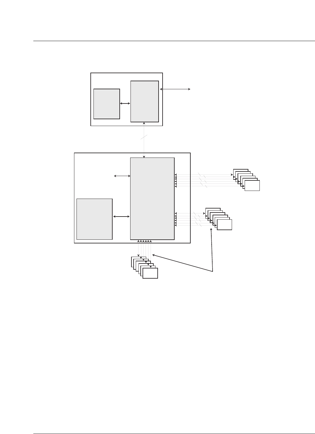
Subsystem description 69
CDMA Metro Cell Functional Description Manual NBSS7.1
Figure 46
Basestation communication network (BCN) distribution
CM
BTSC BTSI
6 T1/E1 Links
CORE
Test BCN
Proc.
De-mux
Mux
FRM
CEM
CEM
32 TDM links over the back plane
BCN multiplexed onto
the high speed serial
links
2 BCN
links
each

70 Subsystem description
411-2133-110 Prototype 01.04 November 1998
DE / RF module signalling
Figure 47
DE/RF module signalling
Signal flow
Forward link baseband signal flow
On the forward path the IB sums the two Channel Cards CDMA forward link
Baseband and multiplexes it with the reverse link BCN traffic from the
Channel cards.Reverse link baseband signal flow
On the reverse path the IB demultiplexes the 650 Mbps serial data from the
CORE and splits it into CDMA forward link BCN data and CDMA reverse
link baseband data.
Digital Enclosure
C
E
M
1
C
E
M
2
C
E
M
3
C
E
M
4
C
E
M
5
C
E
M
6
C
E
M
7
C
E
M
8
C
E
M
9
C
E
M
1
0
C
E
M
1
1
C
E
M
1
2
CORE MODULE 1
Timing and
Frequency Reference BCN
GPS 1
BTS Communications
Network
Timing and
Frequency Reference
Control Module 1
Sampled Tx and Rx + OA&M Signalling + Base Band Voice
Sampled Tx and Rx + OA&M Signalling
T1 / E1
RF Modules
Optical Data
O
p
t
I
/
F
O
p
t
I
/
F
O
p
t
I
/
F
D
S
P
D
S
P
D
S
P
R
F
P
r
o
c
R
F
P
r
o
c
R
F
P
r
o
c
D
u
p
/
L
N
A
D
u
p
/
L
N
A
D
u
p
/
L
N
A

71
CDMA Metro Cell Functional Description Manual NBSS7.1
3Field Replaceable Units (FRU)
The following section lists the Field Replaceable Units (FRU) for the Outdoor
and Indoor Metro Cells and the FRMs. A description of the procedures to
replace the FRUs is found in NTP 411-2133-550 (Metro Cell Maintenance
and Troubleshooting Guide).
3

72 Field Replaceable Units (FRU)
411-2133-110 Prototype 01.04 November 1998
Outdoor Metro Cell
Table 2
Outdoor Metro Cell FRU list
PEC Description
NTGS15AA Heat exchanger internal fan unit
NTGS16AA Heat exchanger external fan unit
NTGS17AA Heater Assembly
NTGS18AA Cooling unit assembly
NT7C25BA Enhanced controller module (ECM)
NT5C15BC Mini-48 rectifier modules
NT7C25PC Slave controller card
NTGS95AA Battery string kit
NTGS30AA Configuration resource module (CORE)
NTGS40AA Control module (CM)
NTGS60AA Channel element module (CEM-24)
NTGS60BA Channel element module (CEM-48)
NTGS50AA GPS module
NTGS53AA FRM duplexer DPM, band A&D
NTGS53AA FRM duplexer DPM, band B&E
NTGS53AA FRM duplexer DPM, band C&F
NTGS53AA FRM duplexer & preselector DPM, band A&D
NTGS53AA FRM duplexer & preselector DPM, band B&E
NTGS53AA FRM duplexer & preselector DPM, band C&F
NTGS54AA FRM EOM - local RE
NTGS54BA FRM EOM - remote RE - short
NTGS54CA FRM EOM - remote RE - long
NTGS54ZA FRM EOM assembly - local RE
NTGS54YA FRM EOM assembly - remote RE - short
-sheet 1 of 2-

Field Replaceable Units (FRU) 73
CDMA Metro Cell Functional Description Manual NBSS7.1
NTGS54XA FRM EOM assembly - remote RE - long
NTGS55AA FRM alarm indicator module
NTGS56AA FRM fan tray assembly
NTGS57AA FRM power amplifier module (PAM)
NTGS58AA FRM transmit / receive module
NTGS7061 Lightning protector
NTGS7069 FRM termination load
Table 3
Indoor Metro Cell FRU list
PEC Description
NTGS18AB Cooling unit assembly
P0874870 Cooling unit filter
NT7C25BA Enhanced controller module (ECM)
NTGS18AB Cooling unit assembly
P0874870 Cooling unit filter
NT5C15BC Mini-48 rectifier modules
NT7C25PC Slave controller card
NTGS30AA Configuration resource module (CORE)
NTGS40AA Control module (CM)
NTGS60AA Channel element module (CEM-24)
NTGS60BA Channel element module (CEM-48)
NTGS50AA GPS module
NTGS53AA FRM duplexer DPM, band A&D
-sheet 1 of 2-
Table 2
Outdoor Metro Cell FRU list (continued)
PEC Description
-sheet 2 of 2-

74 Field Replaceable Units (FRU)
411-2133-110 Prototype 01.04 November 1998
NTGS53BA FRM duplexer DPM, band B&E
NTGS53CA FRM duplexer DPM, band C&F
NTGS53DA FRM duplexer & preselector DPM, band A&D
NTGS53EA FRM duplexer & preselector DPM, band B&E
NTGS53FA FRM duplexer & preselector DPM, band C&F
NTGS54AA FRM EOM local RE
NTGS54BA FRM EOM remote RE - short
NTGS54CA FRM EOM remote RE - long
NTGS54ZA FRM EOM assembly - local RE
NTGS54YA FRM EOM assembly - remote RE - short
NTGS54XA FRM EOM assembly - remote RE - long
NTGS55AA FRM alarm indicator module
NTGS56AA FRM fan tray assembly
NTGS57AA FRM power amplifier module (PAM)
NTGS58AA FRM transmit / receive module
Table 4
FRM Metro Cell FRU list
PEC Description
NTGS89BA FRM duplexer DPM
NTGS89BB FRM duplexer & preselector DPM
NTGS54BA FRM EOM- remote RE- short
NTGS54CA FRM EOM- remote RE- long
NTGS54ZA FRM EOM - assembly - local RE
-sheet 1 of 2-
Table 3
Indoor Metro Cell FRU list (continued)
PEC Description
-sheet 2 of 2-

Field Replaceable Units (FRU) 75
CDMA Metro Cell Functional Description Manual NBSS7.1
NTGS54YA FRM EOM - assembly - remote RE - short
NTGS54XA FRM EOM - assembly - remote RE - long
NTGS55AA FRM alarm indicator module
NTGS56AA FRM fan tray assembly
NTGS5650 FRM plenum assembly
NTGS82AA FRM power amplifier module (PAM)
NTGS85AA 800 MHz FRM transmit / receive module
Table 4
FRM Metro Cell FRU list (continued)
PEC Description (continued)
-sheet 2 of 2-

76 Field Replaceable Units (FRU)
411-2133-110 Prototype 01.04 November 1998

77
CDMA Metro Cell Functional Description Manual NBSS7.1
4Software
Placeholder for Metro Cell software section.
4

78 Software
411-2133-110 Prototype 01.04 November 1998
4

79
CDMA Metro Cell Functional Description Manual NBSS7.1
5Specifications
To be finalized.
5

80 Specifications
411-2133-110 Prototype 01.04 November 1998

81
CDMA Metro Cell Functional Description Manual NBSS7.1
6Glossary
ACN Applications Communication Network
AGC Automatic Gain Control
AM Accounting Management
ASIC Application Specific Integrated Circuit
ATM-UL Asynchronous Transfer Mode - Ultra Lite
BAN Base Station Auxiliary Network
BCN Basestation Communication Network
BIT Built-In Test
BIU Backhaul Interface Unit
BMU Basestation Management Unit
BNC Bayonet Navy Connector
BPM Metro Cell Power Management
6

82 Glossary
411-2133-110 Prototype 01.04 November 1998
BSC Base Station Controller
BSM Base Station Manager
BTSC Basestation Transceiver Subsystem Controller
BTSI Basestation Transceiver Subsystem Interface
CA Corrective Action
CAM Call Manager
CC Channel Card
CDMA Code Division Multiple Access
CIS CDMA Interconnect Subsystem
CLI Command Line Interface
CM Control Module
CM Configuration Management
CMI Call Manager Interface
CMS Channel card Module Shelf
CORE COnfiguration REsource
CPLD CMOS Programmable Logic Device
6

Glossary 83
CDMA Metro Cell Functional Description Manual NBSS7.1
CPU Central Processing Unit
CRC Cyclic Redundancy Check
CRM Call Resource Manager
CSU/DSU Customer Service Unit/Data Service Unit
DDLM Dual Duplexer/LNA Module
DDS Direct Digital Synthesizer
DE Digital Enclosure
DEI Digital Enclosure Interface
DFM Design For Manufacturability
DISCO DIstributor COmbiner
DMS-MTX Digital Multiplex System - Mobile Telephone Exchange
DPM Duplexer / LNA Preselector / LNA Module
DRAM Dynamic RAM
DSP Digital Signal Processor
DTC Data / Digital Trunk Controller
ECC Enhanced Controller Card

84 Glossary
411-2133-110 Prototype 01.04 November 1998
ECL Emitter Coupled Logic
EMC Electro Magnetic Compatibility
EMI Electro Magnetic Interference
EOM Electro Optical Module
EPROM Erasable Programmable Read Only Memory
FA Frequency Assignment
FCC Federal Communication Commission
FER Frame Error Rate
FFA Fast Failure Analysis
FIR Finite Impulse Response
FRU Field Replaceable Unit
FM Fault Management
FRM Flexible Receiver Module
FRC Frequency Reference Card
GPS Global Positioning System
GPSR GPS Receiver

Glossary 85
CDMA Metro Cell Functional Description Manual NBSS7.1
GPSTM Global Position Satellite Timing Module
GUI Graphical User Interface
H/W Hardware
HDLC High level Data Link Control
HPA High Power Amplifier
I/F InterFace
IBN Isolated Bonding Network
IF Intermediate Frequency
IIC Inter-Integrated Circuit
IMC InterModule Communication
LNA Low Noise Amplifier
LO Local Oscillator
LPP Link Peripheral Processor
LTM Loopback Test Mobile
LVD Low Voltage Disconnect
MDS Mini Digital Shelf

86 Glossary
411-2133-110 Prototype 01.04 November 1998
MMI Man Machine Interface
MTBF Mean Time Between Failure
MTX Mobile Telephone Exchange
MUX/DEMUX Multiplex demultiplex
Nc Navy Connector
NM Network Management
OAM Operations Administration and Maintenance
OCM Overhead Channel Message
OCNS Orthogonal Channel Noise Simulator
OEM Original Equipment Manufacturer
OVP Over Voltage Protection
PA Power Amplifier
PAS Product Administration System
PCA Power Converter Assembly
PCB Printed Circuit Board
PCM Pulse Code Modulation

Glossary 87
CDMA Metro Cell Functional Description Manual NBSS7.1
PCP Printed Circuit Pack
PCS Personal Communication System
PEM Power Entry module
PLL Phase Lock Loop
PLM Product Line Management
PM Performance Management
PR Prevent Reoccurrence
PSU Power Supply DC/DC converter
PUPS Point of Use Power Supply
QCELP Qualcomm Code Excited Linear Predictive
RAM Random Access Memory
RCA Root Cause Analysis
RCA Radio CAlibration
RF Radio Frequency
RLM Radio Link Manager
RMS Root Mean Square

88 Glossary
411-2133-110 Prototype 01.04 November 1998
SAC Site Alarm Card
SAW Surface Acoustical Wave
SBS Selector Bank Subsystems
SBSC SBS Controller
SCI Selector Card Interface
SCPA Single Channel Power Amplifier
SCPA Single Channel PA
SCR Single Channel Receiver
SCU Single Channel Upconverter
SCU Sector control Unit
SM Site Management
SM Security Management
SOM Service Option Manager
SRFM Single Channel RFM
SW Software
TBD To Be Determined

Glossary 89
CDMA Metro Cell Functional Description Manual NBSS7.1
TDM Time Division Multiplex
TFU Timing & Frequency Unit
TM Test Management
TNC Threaded Navy Connector
TRM Transmit / Receive Module
TST Three Sector Transceiver
uP micro Processor
UPS Uninterruptable Power Supply
VO Verification Office
VRLA Valve Regulated Lead Acid
XDM eXtended Diagnostic Monitor

90 Glossary
411-2133-110 Prototype 01.04 November 1998

Family Product Manual Contacts Copyright Confidentiality Legal statements DocInfo

CDMA
Metro Cell
Functional Description Manual
Nortel
Department 3431
4300 Emperor
Morrisville, NC 27560
Phone: (800) 684-2273/Fax: (919) 905-5854 / Fax: 684-3977
Copyright 1998 Northern Telecom
NORTHERN TELECOM CONFIDENTIAL: The
information contained in this document is the property of
Northern Telecom. Except as specifically authorized in writing
by Northern Telecom, the holder of this document shall keep the
information contained herein confidential and shall protect same
in whole or in part from disclosure and dissemination to third
parties and use same for evaluation, operation, and maintenance
purposes only.
Information is subject to change without notice.
Metro Cell, DMS-MTX, and MAP are trademarks of Northern
Telecom.
Publication number: 411-2133-110
Product release: NBSS7.1
Document release: Prototype 01.04
Date: November 1998
Printed in the United States of America
92