Avaya Canada NTL100AA TDMA - Dual Mode 800 MHz Enclosure User Manual 000 Frtmatt
Avaya Canada Corporation TDMA - Dual Mode 800 MHz Enclosure 000 Frtmatt
UserManual.wiki
>
Avaya Canada
>
NTL100AA User Manual
>
User Manual
Contents
1.
Exhibit 5 User Documentation
2.
User Manual
User Manual
Navigation menu
Upload a User Manual
Namespaces
Wiki Guide
HTML
PDF
Info
Views
User Manual
Discussion / Help
Navigation


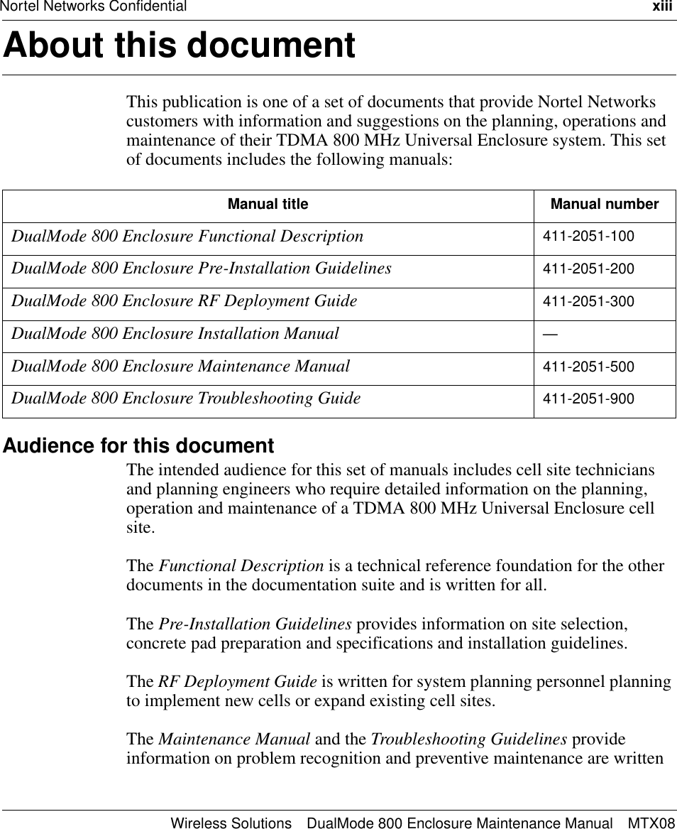
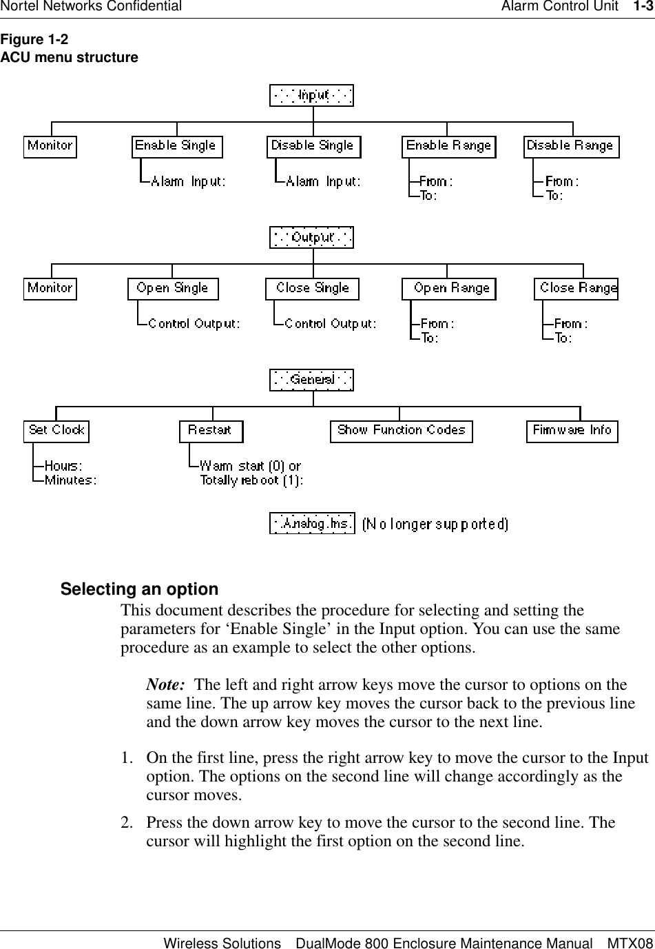
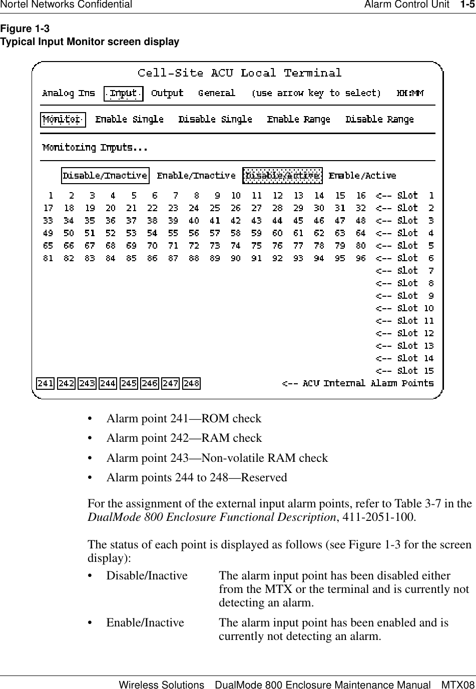
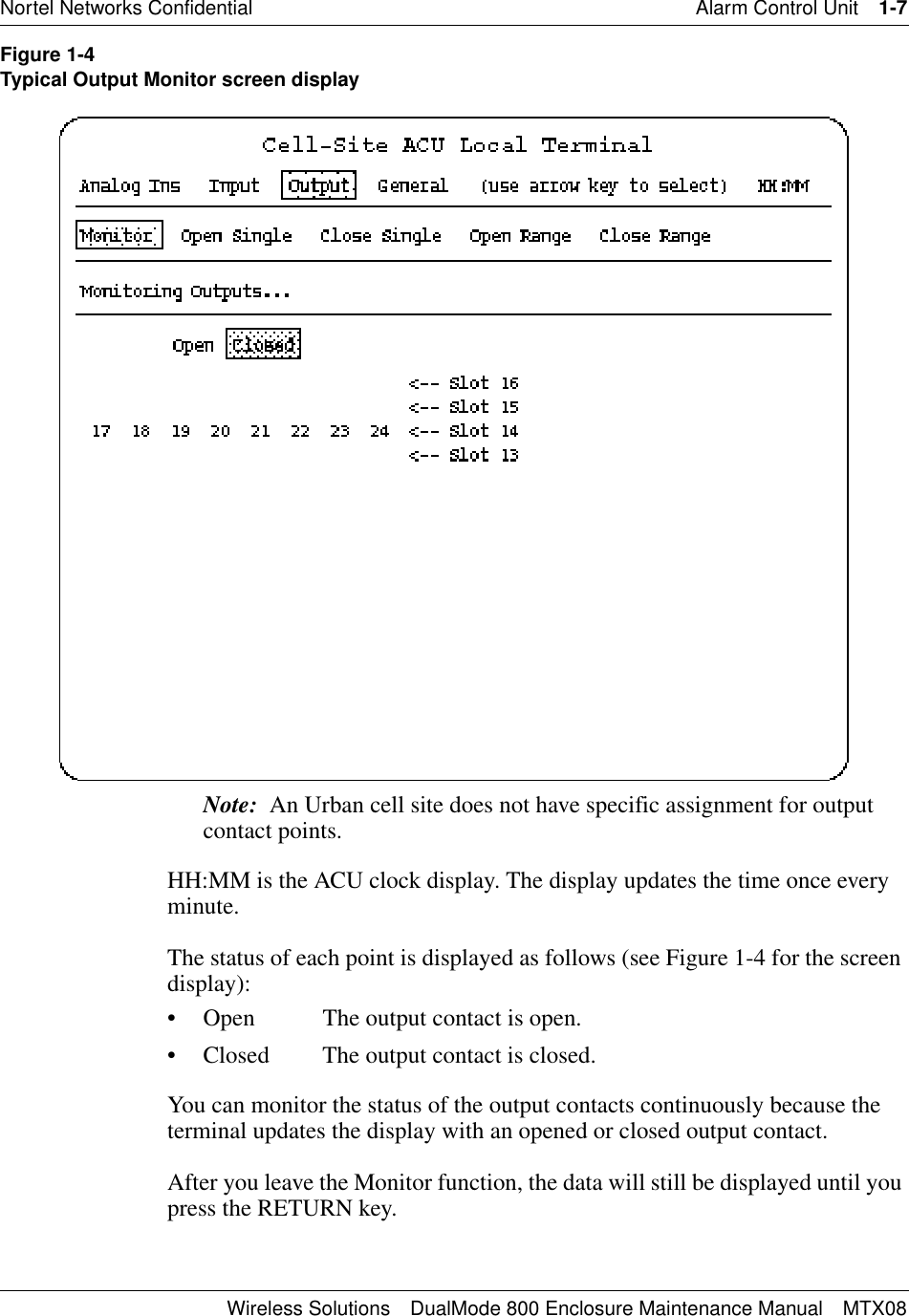

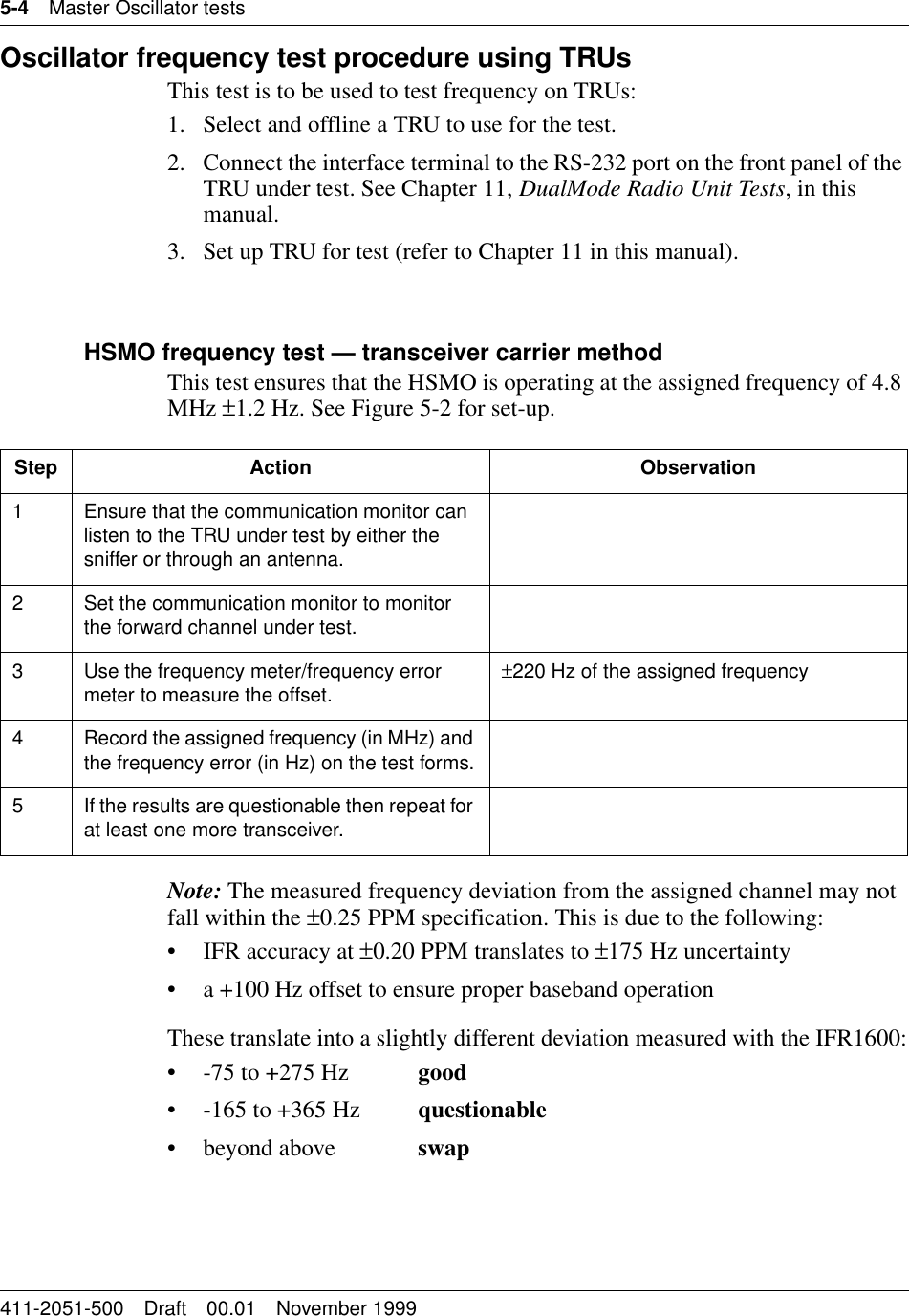


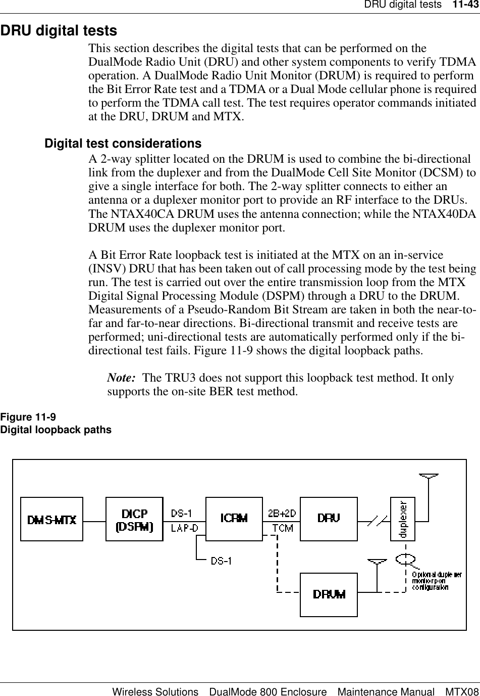
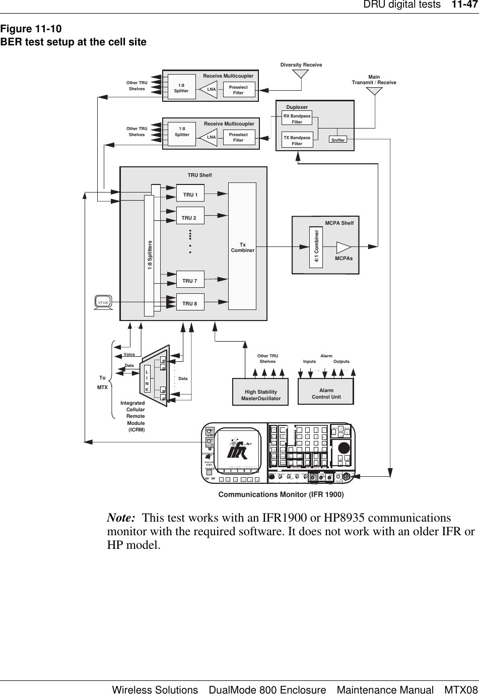
![11-6 DRU tests411-2051-500 Draft 00.01 November 19992. Place the TRU into the command line mode by pressing the “Break” key on the interface terminal. The terminal will display the following:TRU Terminal InterfaceCopyright 1990,1991 Bell Northern Research, Inc.>3. To place the TRU into the fullscreen monitor mode, enter:>SET LT OFF (disables the LAPD timeout)>SET FS ON (invokes fullscreen display)This places the TRU into the fullscreen AMPS mode (refer to Figure 1-8).TRU EEPROM CRC Check4. Check the top right corner of the screen and verify that the EEPROM CRC Check has passed. The EEPROM CRC Check on the screen (refer to Figure 1-8 in Chapter 1, Equipment operation) will show:EEPROM CRC Check: PASSEDRecord the result. If the check fails, replace the TRU.5. Disconnect the interface terminal from the TRU under test.DRU configurations for analog testsThe Transmit Receive Unit (TRU) must be correctly configured for each test. This section covers the general test set-ups for the TRU.Nominal Application GainIn a DualMode 800 Enclosure, all TRUs are set to “patype none” mode during installation. In this mode, the nominal application gain is set to a default value of -12 dB and the TRU maximum transmit power is set to a default value of +15 dBm. Do not change these default settings during the tests.With default settings in the “patype none” mode, the output of the TRU is set to [+15 - (-12)] = +27 dBm at the TRU backplane. Therefore, when checking the TRU output with the “query pastatus” command, please remember that the +15 dBm TRU output has been compansated for by the -12 dB norminal application gain to give an actual TRU output of +27 dBm at default.](https://usermanual.wiki/Avaya-Canada/NTL100AA.User-Manual/User-Guide-68813-Page-144.png)