Avaya Canada NTL100AA TDMA - Dual Mode 800 MHz Enclosure User Manual 000 Frtmatt
Avaya Canada Corporation TDMA - Dual Mode 800 MHz Enclosure 000 Frtmatt
Contents
- 1. Exhibit 5 User Documentation
- 2. User Manual
User Manual

Wireless Solutions
DualMode 800 Enclosure
Maintenance Manual
MTX08 Draft 00.01 November 1999
DRAFT
411-2051-500


Wireless Solutions
DualMode 800 Enclosure
Maintenance Manual
Document number: 411-2051-500
Product release: MTX08
Document version: Draft 00.01
Date: November 1999
Copyright Country of printing Confidentiality Legal statements Trademarks
Copyright 1999 Nortel Networks Corporation, All Rights Reserved
Printed in Canada
NORTEL NETWORKS CONFIDENTIAL
The information contained herein is the property of Nortel Networks and is strictly confidential. Except as expressly authorized in
writing by Nortel Networks, the holder shall keep all information contained herein confidential, shall disclose it only to its employees
with a need to know, and shall protect it, in whole or in part, from disclosure and dissemination to third parties with the same degree
of care it uses to protect its own confidential information, but with no less than reasonable care. Except as expressly authorized in
writing by Nortel Networks, the holder is granted no rights to use the information contained herein.
Information is subject to change without notice. Nortel Networks reserves the right to make changes in design or components as
progress in engineering and manufacturing may warrant.
This equipment generates, uses and can radiate radio frequency energy. If not installed and used in accordance with the instruction
manual, this equipment may cause harmful interference to radio communications. Operation of this equipment in a residential
area is likely to cause harmful interference, in which case the user will be required to correct the interference at their own expense.
DMS, DMS-MTX, DualMode, MAP and NORTEL are trademarks of Nortel Networks.
Trademarks are acknowledged with an asterisk (*) at their first appearance in the document.


Nortel Networks Confidential v
Wireless Solutions DualMode 800 Enclosure Maintenance Manual MTX08
Publication history
October 1999
Draft 00.01. Draft issue of document for internal review.

vi Publication history Nortel Networks Confidential
411-2051-500 Draft 00.01 November 1999

Nortel Networks Confidential vii
Wireless Solutions DualMode 800 Enclosure Maintenance Manual MTX08
Contents 1
About this document xiii
Audience for this document xiii
Organization of this document xiv
Related documents xiv
Equipment operation 1-1
Alarm Control Unit 1-1
Selecting an option 1-3
Input option 1-4
Output option 1-6
General option 1-8
DualMode Cell Site Monitor (DCSM) 1-9
Stand-alone mode operation 1-10
The Hughes M6200 handset (NT3P75AB) 1-10
Programming the mobile 1-12
Operating the mobile 1-21
Transmit Receive Unit (TRU) 1-22
The front panel display interface 1-22
The Terminal Interface 1-26
Fullscreen commands 1-31
Command line mode commands 1-36
Multi-Channel Power Amplifier (MCPA) 1-43
Installing the MCPA software program 1-43
Running the MCPA software on the computer 1-43
Downloading the MCPA firmware to the MCPA shelf (if required) 1-46
Setting the MCPA output power 1-47
Periodic maintenance 2-1
Periodic maintenance records 2-1
Equipment in a DualMode 800 Enclosure 2-2
Transmit Receive Unit (TRU) and Multi-Channel Power Amplifier (MCPA) 2-3
High Stability Master Oscillator (HSMO) 2-3
Alarm Control Unit (ACU) 2-3
Transmit path insertion loss 2-3
Other equipment 2-3
Transmission facilities 2-3
Microwave 2-4

viii Contents Nortel Networks Confidential
411-2051-500 Draft 00.01 November 1999
Copper audio link 2-4
Power 2-4
Battery 2-4
Rectifiers 2-4
Fuses/breakers 2-4
Cabling and connections 2-4
Inside grounding 2-4
Bay bonding 2-5
Cabling and connections 2-5
Principle ground bar 2-5
Transmission line entrance 2-5
Outside grounding 2-5
Tower and associated structures 2-5
Building sheath, fences and other equipment 2-6
Antennas and tower 2-6
Structure 2-6
Tower lighting 2-6
Grounding 2-6
Paint 2-6
Feed 2-7
Antennas 2-7
Pressurized transmission lines 2-7
Site performance 2-7
Fringe coverage 2-7
Handoff checks 2-7
Antenna sweep 2-7
Housekeeping 2-8
Heating/air conditioning 2-8
Dust control 2-8
Statutory requirements 2-8
Site licenses 2-8
Trash and loose articles 2-8
Site grounds keeping 2-8
Building service 2-8
Security 2-8
Manuals and records 2-9
Schedule for periodic cell site maintenance 2-9
DualMode 800 Enclosure Maintenance Reference Chart 2-10
DualMode 800 Enclosure Every Visit Checklist 2-13
DualMode 800 Enclosure MONTHLY Checklist 2-14
DualMode 800 Enclosure QUARTERLY Checklist 2-15
DualMode 800 Enclosure SEMI-ANNUAL Checklist 2-16
DualMode 800 Enclosure ANNUAL Checklist 2-17
Test equipment and precautions 3-1
Test equipment 3-1
Precautions 3-3
Equipment warm-up 3-3
Test equipment 3-3
RF radiation hazard 3-4

Nortel Networks Confidential Contents ix
Wireless Solutions DualMode 800 Enclosure Maintenance Manual MTX08
Electrostatic Discharge (ESD) control 3-4
Power-up procedure 4-1
Overview 4-1
DC power inspection 4-1
Voltage checks 4-2
Master Oscillator tests 5-1
Overview 5-1
Oscillator frequency specifications 5-1
Oscillator power level test 5-2
Reference oscillator tests 5-2
Oscillator frequency test procedure using TRUs 5-4
HSMO frequency test — transceiver carrier method 5-4
Antenna and transmission line tests 6-1
Antenna direct current continuity 6-1
Antenna return loss 6-2
Antenna return loss test 6-2
Thruline wattmeter method (Antenna return loss) 6-4
Antenna sweep 6-4
Enhanced Receive Multicoupler (ERMC) tests 7-1
ERMC description 7-1
ERMC overall gain measurement test 7-1
ERMC gain adjustment 7-4
Talk-In/Talk-out (TITO) balance test 7-4
TITO test procedure 7-5
Alarm Control Unit (ACU) tests 8-1
Overview 8-1
Alarm Control Unit test setup 8-1
Performing tests using a DCSM 9-1
Introduction 9-1
Stand-alone mode tests 9-1
Stand-alone ACCH/DCCH selection 9-1
DCSM auto answer facilities 9-2
Performing tests using the DCSM in the directed mode 9-2
Monitoring functions 9-2
Posting the DCSM 9-4
Control Channel tests 9-4
MTX CTT tests 9-9
ICRM tests 10-1
DRU tests 11-1
Introduction 11-1
Functionality of the DRU 11-3

xContents Nortel Networks Confidential
411-2051-500 Draft 00.01 November 1999
Audio sensitivity of the TRU 11-3
Test considerations 11-4
Test equipment required 11-5
TRU self test 11-5
DRU configurations for analog tests 11-6
Nominal Application Gain 11-6
TRU setup 11-7
DRU transmit tests 11-12
Service impacts 11-12
Transmit test setup procedure 11-12
Transmit Carrier Frequency test 11-15
Wideband Modulation test 11-15
SAT Frequency and Deviation tests 11-16
Residual Modulation test 11-17
Transmit Audio Level test 11-17
Modulation Limiting test 11-18
1 kHz Tone Generation test 11-20
Setting TX audio deviation to site operational level 11-21
DRU receive tests 11-22
Service impacts 11-22
Receive test setup procedure 11-22
Receive sensitivity test 11-25
Receive and transmit audio line sensitivity test 11-25
Receive audio level test 11-26
RSSI test 11-27
RSSI offset calibration 11-29
SAT detect test 11-35
ST detect test 11-36
Setting RX audio level to site operational level 11-37
Transmit RF output power test 11-38
Transmit RF output power test setup procedure 11-38
Requirements on the Transmit RF output power test 11-40
Transmit RF output power test 11-41
Setting TRU power step size and Max power to site operational level 11-42
DRU digital tests 11-43
Digital test considerations 11-43
Bit error rate test at the MTX switch 11-44
Bit error rate test at the cell site 11-46
TDMA modulation accuracy test 11-49
TDMA call test 11-52
Enclosure maintenance 12-1
Field Replaceable Unit (FRU) 12-1
General precautions 12-4
RF radiation hazard 12-4
Electrostatic Discharge (ESD) control 12-4
Cable/connector identification 12-4
Replacing faulty common equipment (CE) units 12-5
Replacing faulty radio frequency (RF) units 12-6
Replacing the TRU or MCPA shelf 12-7

Nortel Networks Confidential Contents xi
Wireless Solutions DualMode 800 Enclosure Maintenance Manual MTX08
General rules for replacing a TRU or an MCPA module 12-7
Replacing the TRU 12-7
Replacing the MCPA module 12-8
Returning a faulty unit to your Nortel Networks CSO office 12-9
Appendix A: Frequency table A-1
System's channel and frequency 1
Channel frequency calculation (in the following, N = channel number) A-1
AMPS frequency allocation A-1
Appendix B: Test forms B-1
Power and grounding checks (Chapter 4) B-2
HSMO checks (Chapter 5) B-3
Antenna checks (Chapter 6) B-3
DRU checks — Transmit tests (Chapter 11) B-4
DRU checks — Receive tests (Chapter 11) B-5
DRU checks — Digital tests (Chapter 11) B-6
Figures
Figure 2-1 ACU Initial screen display 2-2
Figure 2-2 ACU menu structure 2-3
Figure 2-3 Typical Input Monitor screen display 2-5
Figure 2-4 Typical Output Monitor screen display 2-7
Figure 2-5 Controls and keypad on Hughes M6200 handset 2-10
Figure 2-6 Front panel layout of the TRU2 (NTAX98AA) 2-22
Figure 2-7 Front panel layout of the TRU3 2-23
Figure 2-8 Fullscreen display for the TRU2 2-29
Figure 2-9 Fullscreen display for the TRU3 2-30
Figure 2-10 Selection menu for the MCPA 2-44
Figure 2-11 Power setting menu for the MCPA 2-44
Figure 3-1 Equipment layout of a DualMode 800 Enclosure 3-2
Figure 6-1 Oscillator power level and frequency test setup 6-3
Figure 6-2 Oscillator frequency test setup — transceiver carrier method 6-5
Figure 7-1 Antenna return loss block diagram 7-3
Figure 8-1 RMC overall gain measurement test 8-3
Figure 8-2 Talk-In/Talk-out call setup 8-5
Figure 9-1 ACU First maintenance screen 9-2
Figure 9-2 Typical alarm connector (36-Pin) 9-3
Figure 10-1 MALT and MAHT CTTPARMS Fields 10-10
Figure 10-2 MALT Test Output MTX303 Log 10-11
Figure 10-3 MAHT Test Output MTX303 Log 10-11
Figure 10-4 MRLT and MRHT CTTPARMS fields 10-13
Figure 10-5 MRLT Test Output MTX303 Log 10-14
Figure 10-6 MRHT Test Output MTX303 Log 10-14
Figure 10-7 MRLP Test Measurements 10-15
Figure 10-8 MRLP Test results MTX302 Log 10-16
Figure 10-9 MRLR Test Measurements 10-18
Figure 10-10 MRLR Test results MTX302 Log 10-19
Figure 11-1 Front panel layout of the TRU2 (NTAX98AA) 11-2
Figure 11-2 Front panel layout of the TRU3 (NTAW99AA) 11-2

xii Contents Nortel Networks Confidential
411-2051-500 Draft 00.01 November 1999
Figure 11-3 MCPA front panel layout 11-3
Figure 11-4 DRU transmit tests setup (service affecting) 11-14
Figure 11-5 DRU receive tests setup (shelf/site service affecting) 11-24
Figure 11-6 RSSI offset setup 11-29
Figure 11-7 Transmit RF output power test setup 11-39
Figure 11-8 Transmit power level of a DualMode 800 Enclosure with 24-channel per
cell/sector using two MCPA modules 11-41
Figure 11-9 Digital loopback paths 11-43
Figure 11-10 BER test setup at the cell site 11-47
Tables
Table 1-1 Transitions in the TRU3 LED state 1-24
Table 1-2 TRU Fullscreen command summary 1-31
Table 1-3 TRU Fullscreen commands 1-32
Table 1-4 Command line mode maintenance commands 1-36
Table 1-5 Command line mode measurement commands 1-40
Table 1-6 Command line mode test commands 1-42
Table 2-1 Maintenance schedule example 2-9
Table 3-1 DRU to Interface Terminal connection 3-2
Table 4-1 Minimum bending radii of power cables 4-2
Table 4-2 RIP1 circuit breaker assignments and ratings 4-3
Table 4-3 RIP2 circuit breaker assignments and ratings 4-3
Table 4-4 RIP3 circuit breaker assignments and ratings 4-3
Table 9-1 Naming convention of the MTX trunk tests 5-9
Table 11-1 DRU configurations for analog tests 11-8
Table 11-2 RSSI characteristics 11-28
Table 11-3 DRU configuration for RSSI characteristics 11-34
Table 11-4 RSSI measurement characteristics 11-34
Table 11-5 Nominal DualMode 800 Enclosure per-carrier power level at the output
port of the MCPA shelf 11-40
Table 12-1 DualMode Urban field replaceable units 12-1
Procedures
Procedure 9-1 Posting the DCSM 9-4
Procedure 9-2 Control Channel test set-up 9-5
Procedure 9-3 Measuring forward CCH RF power 9-6
Procedure 9-4 Measuring reverse CCH RF power 9-6
Procedure 9-5 Round Robin Monitoring 9-7
Procedure 9-6 Querying ACCH OMT parameters 9-8
Procedure 9-7 Querying the DCSM parameters 9-8
Procedure 9-8 Initiating the MALT/MAHT test 9-11
Procedure 9-9 Initiating the MRLT/MRHT tests 9-13
Procedure 9-10 Initiating the MRLP test 9-16
Procedure 9-11 Initiating the MRLR test 9-18
Procedure 9-12Invoking the DTRM or MTRM tests 9-20

Nortel Networks Confidential xiii
Wireless Solutions DualMode 800 Enclosure Maintenance Manual MTX08
About this document 1
This publication is one of a set of documents that provide Nortel Networks
customers with information and suggestions on the planning, operations and
maintenance of their TDMA 800 MHz Universal Enclosure system. This set
of documents includes the following manuals:
Audience for this document
The intended audience for this set of manuals includes cell site technicians
and planning engineers who require detailed information on the planning,
operation and maintenance of a TDMA 800 MHz Universal Enclosure cell
site.
The Functional Description is a technical reference foundation for the other
documents in the documentation suite and is written for all.
The Pre-Installation Guidelines provides information on site selection,
concrete pad preparation and specifications and installation guidelines.
The RF Deployment Guide is written for system planning personnel planning
to implement new cells or expand existing cell sites.
The Maintenance Manual and the Troubleshooting Guidelines provide
information on problem recognition and preventive maintenance are written
Manual title Manual number
DualMode 800 Enclosure Functional Description 411-2051-100
DualMode 800 Enclosure Pre-Installation Guidelines 411-2051-200
DualMode 800 Enclosure RF Deployment Guide 411-2051-300
DualMode 800 Enclosure Installation Manual —
DualMode 800 Enclosure Maintenance Manual 411-2051-500
DualMode 800 Enclosure Troubleshooting Guide 411-2051-900

xiv About this document Nortel Networks Confidential
411-2051-500 Draft 00.01 November 1999
for the cell site technician to assist in troubleshooting and performing routine
work.
The document suite assumes that the reader has a basic knowledge of cellular
systems and radio propagation and is familiar with measurement units and
terms associated with these concepts. This document does not provide
detailed information on the theory of switching and radio propagation.
Organization of this document
This publication is organized to present the following information:
• overview of the TDMA 800 MHz Universal Enclosure, highlighting the
components
• layout of the equipment bays, interface module and battery pedestal
• detailed descriptions of the TDMA 800 MHz equipment, both standard
components and thoses specific to the enclosure. RF paths, channel
expansion, and field-replaceable units are also included.
• discussion of the environmental control systems (heating/cooling)
• the power systems of the enclosure, as well as grounding requirements
• technical specifications of the enclosure
• list of terms (acronyms and abbreviations)
Related documents

Nortel Networks Confidential 1-1
Wireless Solutions DualMode 800 Enclosure Maintenance Manual MTX08
Equipment operation 1
In a DualMode 800 Enclosure, you can communicate with the Alarm Control
Unit (ACU), the Transmit Receive Unit (TRU) and the Multi-Channel Power
Amplifier (MCPA) by the use of an interface terminal or a computer. You can
use the handset on the DualMode Cell Site Monitor (DCSM) to program the
mobile unit and perform call through test.
This chapter describes the interface commands for configuring and
programming these units in the DualMode 800 Enclosure.
Alarm Control Unit
The MAINTENANCE (Local Terminal) port located on the front of the ACU
gives direct access to the ACU MPU board. You can use this interface to
configure and monitor the alarm input points and the control output contacts.
To access the ACU for local maintenance and monitoring, you need a VT100
(or equivalent) terminal with the following settings:
Stop bit control 1 bit
Word length 8 bits
Parity none
BAUD rate 9600
Interface RS-232C
If you cannot set the terminal to the settings listed, change the ACU
configuration by setting the local terminal switch (SW3) on the MPU board to
match your terminal settings. Refer to Table 5-4 for the settings of SW3 in the
DualMode 800 Enclosure Functional Description, 411-2051-100.
When the terminal and ACU are set correctly, connect the terminal to the
MAINTENANCE port with a null modem cable. Power up the terminal, hold
the CONTROL key and press the Z key. A menu of options will appear on the
screen as shown in Figure 1-1.
1-2 Equipment operation Nortel Networks Confidential
411-2051-500 Draft 00.01 November 1999
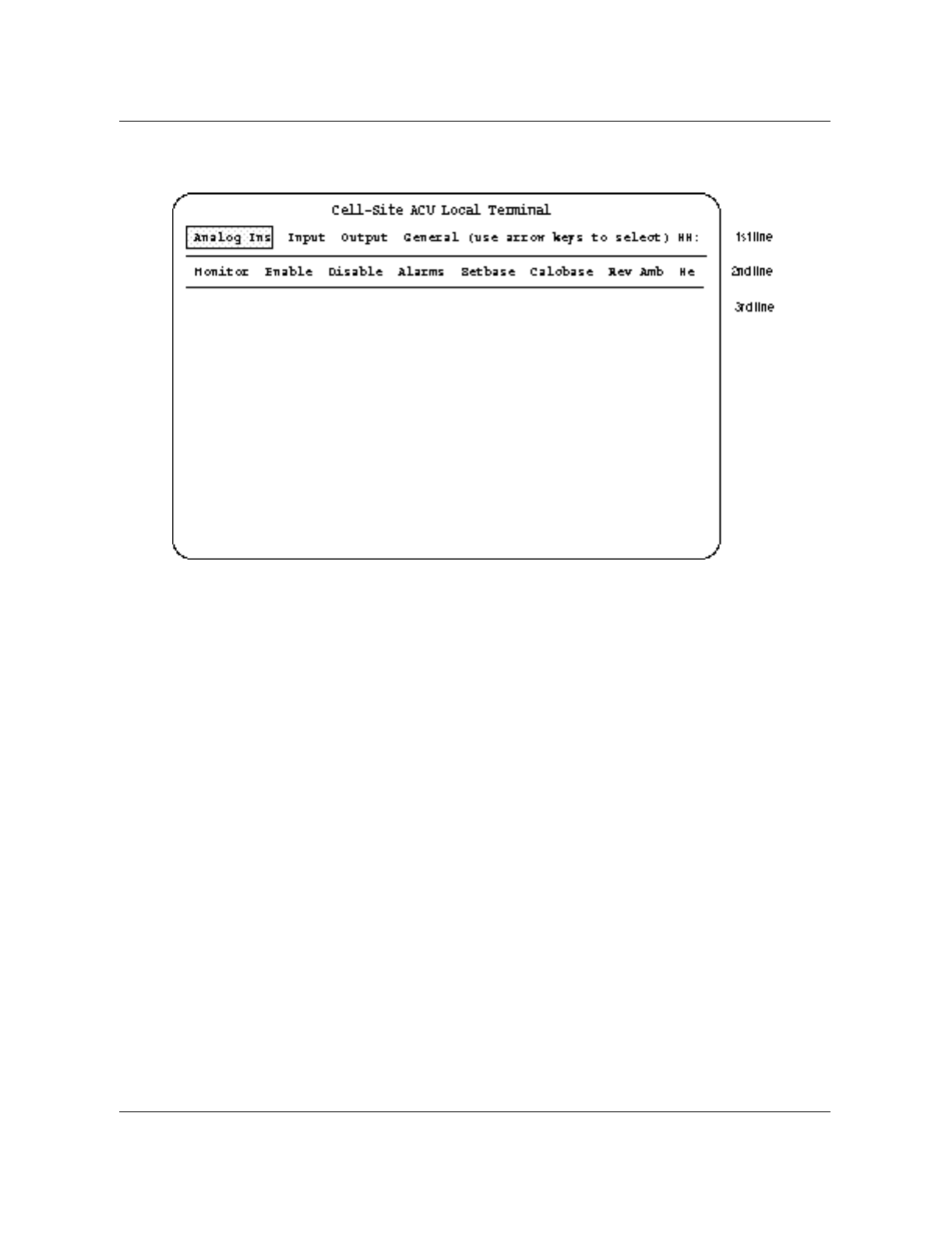
Figure 1-1
ACU Initial screen display
You can choose one of the four primary options at the first level:
• Input
• Output
• General
• Analog Ins (not used)
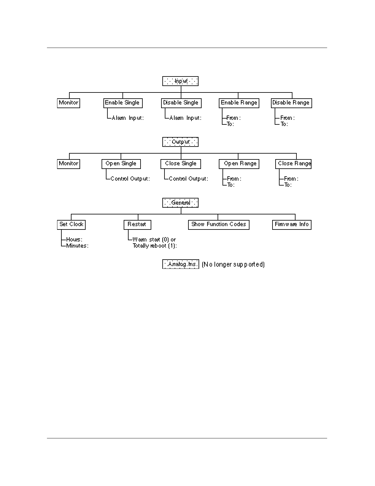
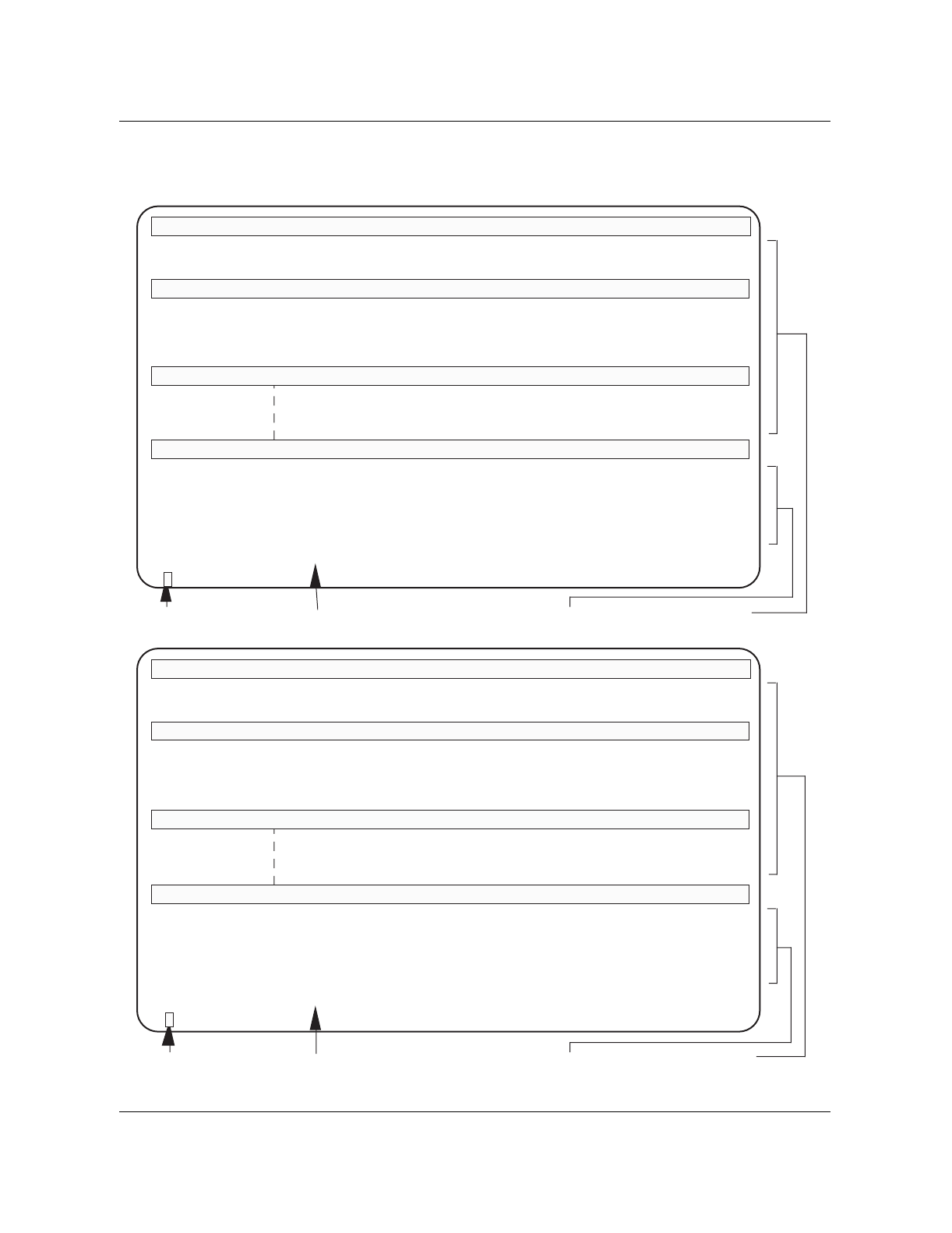
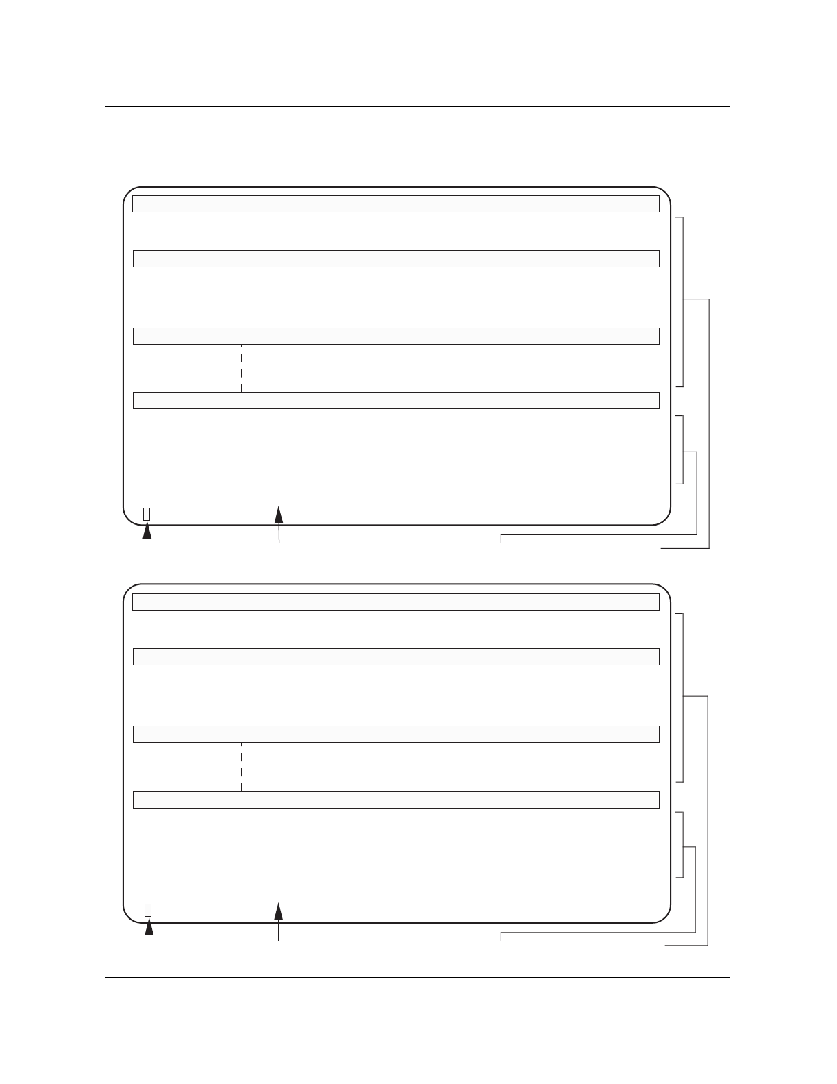
Each option consists of up to three lines on the screen. Figure 1-2 shows the
structure of these options.
Nortel Networks Confidential Alarm Control Unit 1-3
Wireless Solutions DualMode 800 Enclosure Maintenance Manual MTX08
Figure 1-2
ACU menu structure
Selecting an option
This document describes the procedure for selecting and setting the
parameters for ‘Enable Single’ in the Input option. You can use the same
procedure as an example to select the other options.
Note: The left and right arrow keys move the cursor to options on the
same line. The up arrow key moves the cursor back to the previous line
and the down arrow key moves the cursor to the next line.
1. On the first line, press the right arrow key to move the cursor to the Input
option. The options on the second line will change accordingly as the
cursor moves.
2. Press the down arrow key to move the cursor to the second line. The
cursor will highlight the first option on the second line.

1-4 Equipment operation Nortel Networks Confidential
411-2051-500 Draft 00.01 November 1999
3. On the second line, press the right arrow key to move the cursor to the
Enable Single option. The options on the third line will change
accordingly as the cursor moves.
4. Press the down arrow key to move the cursor to the third line. The cursor
will highlight the first option on the third line.
5. On the third line, type in the number of the alarm input point that needs to
be enabled. Press the Return key.
Note: For options that have more than one parameter on the third line, use
the left and right arrow keys to move the cursor from one parameter to
another parameter.
6. Press the Return key a second time to execute the selected parameter of
the option. The display will show:
Command Sent...Acknowledge Received
7. Press the up arrow key to move the cursor back to the previous line.
Note: The ‘Monitor’, ‘Show Function Codes’ and ‘Firmware Info’
options do not have a third line on the menu. When selecting these
options, press the Return key after they are selected. The information for
these options will appear on the display.
Input option
You can select the following five functions under the Input option:
• Monitor
• Enable Single
• Disable Single
• Enable Range
• Disable Range
Monitor
This function monitors the status of each alarm input point. Figure 1-3 shows
a typical screen display of the Input Monitor option.
Nortel Networks Confidential Alarm Control Unit 1-5
Wireless Solutions DualMode 800 Enclosure Maintenance Manual MTX08
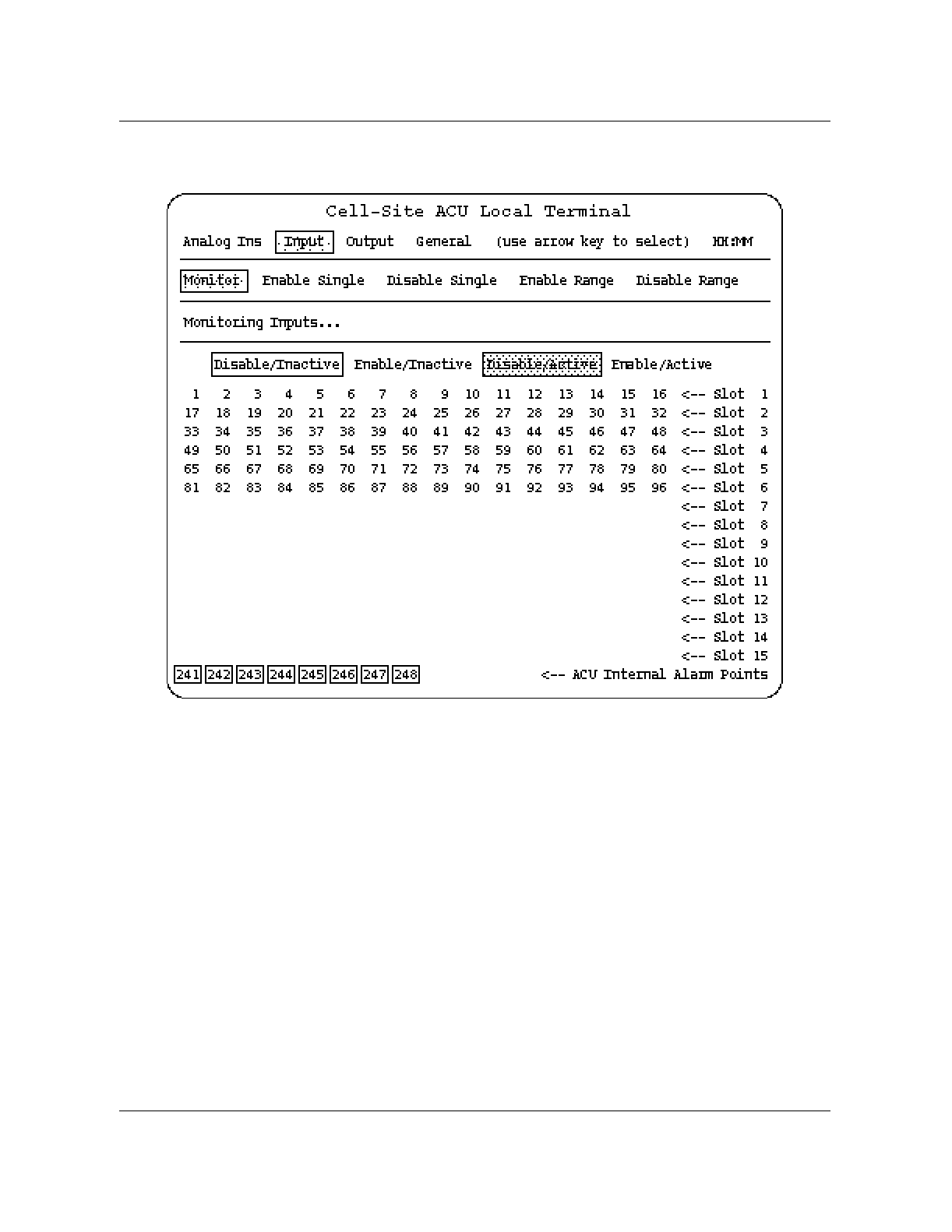
Figure 1-3
Typical Input Monitor screen display
• Alarm point 241—ROM check
• Alarm point 242—RAM check
• Alarm point 243—Non-volatile RAM check
• Alarm points 244 to 248—Reserved
For the assignment of the external input alarm points, refer to Table 3-7 in the
DualMode 800 Enclosure Functional Description, 411-2051-100.
The status of each point is displayed as follows (see Figure 1-3 for the screen
display):
• Disable/Inactive The alarm input point has been disabled either
from the MTX or the terminal and is currently not
detecting an alarm.
• Enable/Inactive The alarm input point has been enabled and is
currently not detecting an alarm.

1-6 Equipment operation Nortel Networks Confidential
411-2051-500 Draft 00.01 November 1999
• Disable/Active The alarm input point has been disabled. It is
currently detecting an alarm which, because it is
disabled, will not be reported to the MTX.
• Enable/Active The alarm input point has been enabled. It is
currently detecting an alarm that has been reported
to the MTX.
You can monitor the status of the alarms continuously because the terminal
automatically updates the display every second while in the Monitor mode.
After you leave the Monitor function, the data will still be displayed until you
press the RETURN key.
Enable Single
The Enable Single function enables input alarm points one at a time. You
must enable an input alarm point before it will report alarm conditions to the
MTX.
Disable Single
The Disable Single function disables input alarm points one at a time. A
disabled input alarm point will not report alarm conditions to the MTX.
Enable Range
The Enable Range function enables a group of input alarm point at a time.
Disable Range
The Disable Range function disables a group of input alarm point at a time.
Output option
You can select the following five functions under the Output option:
• Monitor
• Open Single
• Close Single
• Open Range
• Close Range
Monitor
This function monitors the status of each output contact point. Figure 1-4
shows a typical screen display of the Output Monitor option.
Nortel Networks Confidential Alarm Control Unit 1-7
Wireless Solutions DualMode 800 Enclosure Maintenance Manual MTX08
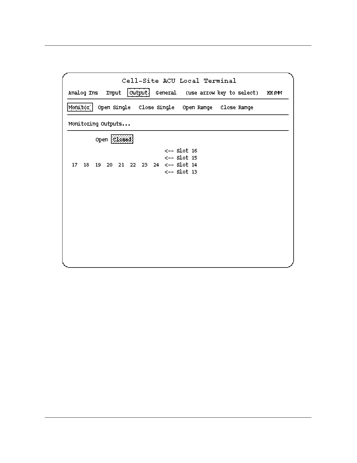
Figure 1-4
Typical Output Monitor screen display
Note: An Urban cell site does not have specific assignment for output
contact points.
HH:MM is the ACU clock display. The display updates the time once every
minute.
The status of each point is displayed as follows (see Figure 1-4 for the screen
display):
• Open The output contact is open.
• Closed The output contact is closed.
You can monitor the status of the output contacts continuously because the
terminal updates the display with an opened or closed output contact.
After you leave the Monitor function, the data will still be displayed until you
press the RETURN key.

1-8 Equipment operation Nortel Networks Confidential
411-2051-500 Draft 00.01 November 1999
Open Single
The Open Single function opens output contact points one at a time. Setting
an output contact point to Open disables that output point.
Close Single
The Close Single function closes output contact points one at a time. Setting
an output contact point to Closed enables that contact point.
Open Range
The Open Range function opens a group of output contact points at a time.
Close Range
The Close Range function closes a group of output contact points at a time.
General option
You can select the following four functions under the General option.
•Set Clock
•Restart
• Show Function Codes
• Firmware Info
Set Clock
The ACU clock determines the time alarms are generated. This option allows
you to set the time on a 24-hour basis.
Restart
This function restores the alarm input points and output contacts of the ACU
to the default states.
Show Function Codes
This function displays the function codes the system uses on messages
between the MTX and the ACU.
Firmware Info
You can display information about the existing firmware load in the ACU.
Nortel Networks Confidential DualMode Cell Site Monitor (DCSM) 1-9
Wireless Solutions DualMode 800 Enclosure Maintenance Manual MTX08
DualMode Cell Site Monitor (DCSM)
The DualMode Cell Site Monitor (DCSM) can operate in two modes, stand-
alone and directed. In stand-alone mode, the DCSM functions like a normal
mobile telephone. In directed mode, the DCSM performs test functions under
the control of the MTX.
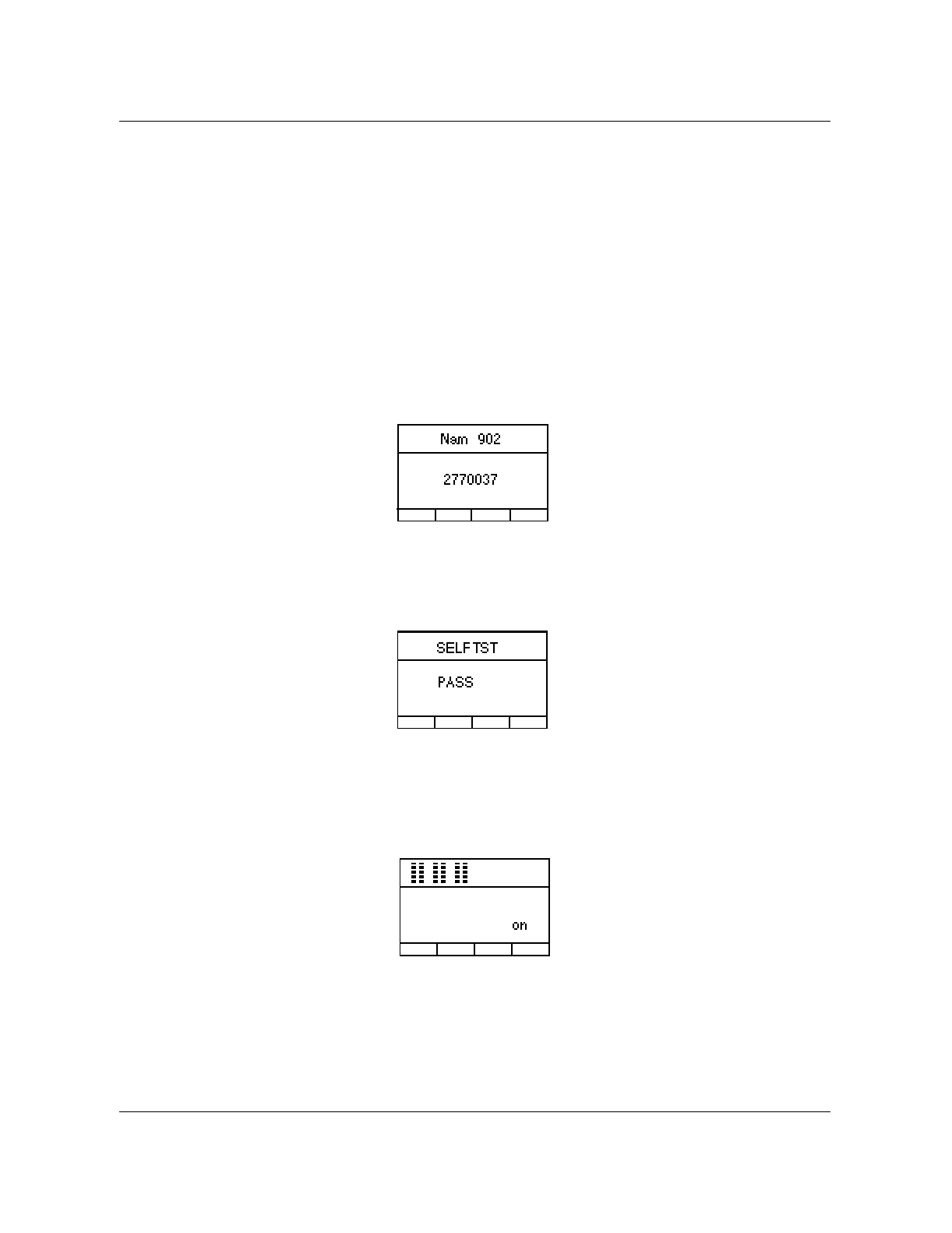
When you power up or reset a DCSM, the DCSM performs a self-test.
Note: During power up, it may take as long as four minutes for the
DCSM to startup.
The display on the handset first shows the phone number of the mobile unit.
On a successful self-test, the display shows the SELFTST PASS message.
The DCSM is in stand-alone mode after the self-test. The display shows that
the mobile unit is on and is ready for originating and answering calls.
1-10 Equipment operation Nortel Networks Confidential
411-2051-500 Draft 00.01 November 1999
Stand-alone mode operation
In stand-alone mode you can use the handset on the front panel of the DCSM
to originate and answer calls.
The mobile unit functions in the same way as a subscriber mobile telephone
in the cellular system. For this reason, the mobile unit in the DCSM has to be
activated in the same way as a subscriber mobile telephone. The cellular
system will not recognize the mobile unit or allow it to function unless the
programming on the Numerical Assignment Modules (NAM) is completed.
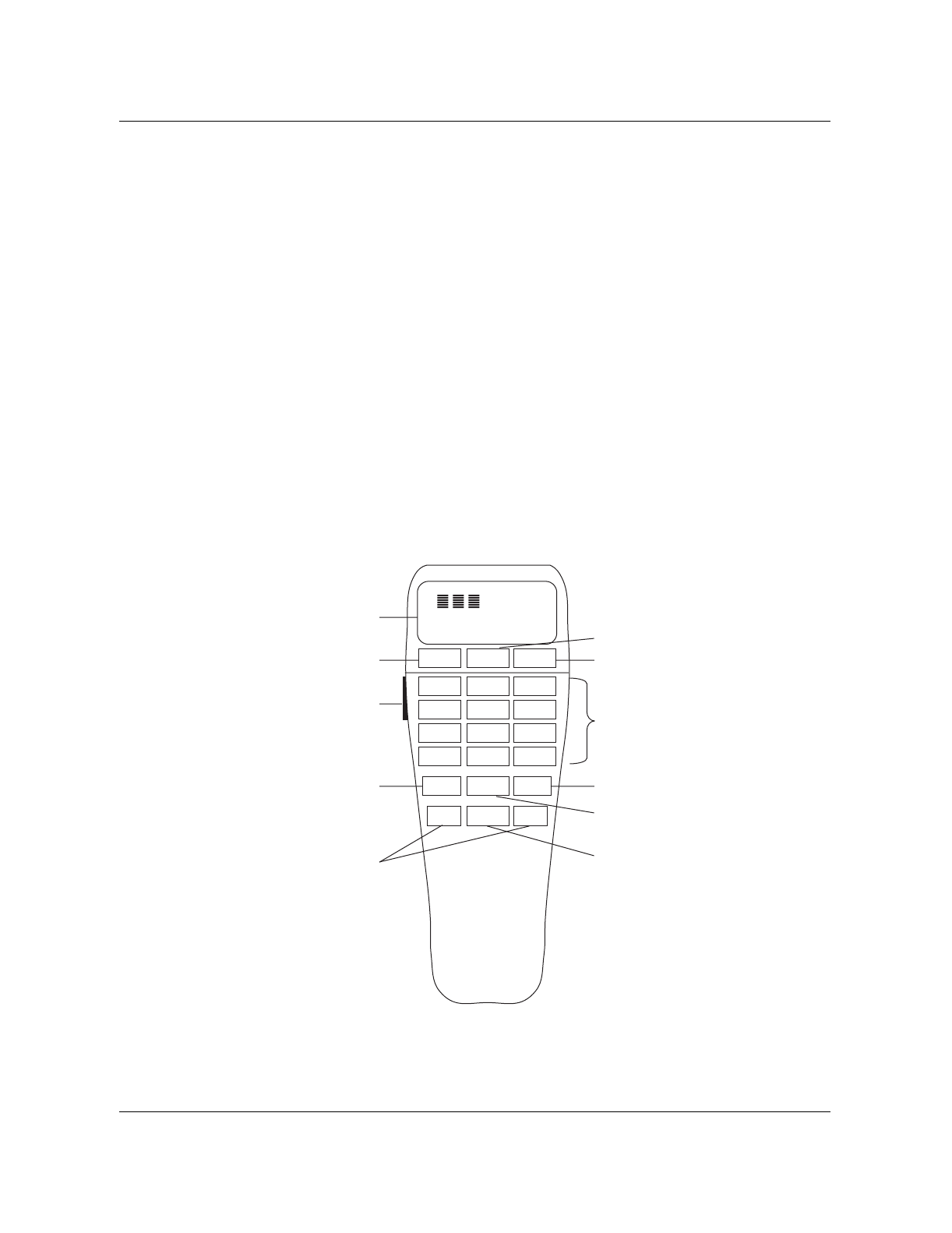
The Hughes M6200 handset (NT3P75AB)
The Hughes M6200 cellular telephone is used as the mobile unit in the
DCSM. Figure 1-5 shows the location of controls and keypad on the Hughes
M6200 handset.
Figure 1-5
Controls and keypad on Hughes M6200 handset
SND PWR END
123
456
789
*0 #
RCL CLR STO
M1 FCN M2
QZ ABC DEF
GHI JKL MNO
PRS TUV WXY
InUse Roam NoSvc Digital
on
Display
Up/Down Volume
Control Button
Send Key End Key
Power Key
Digit Keys
Clear Key
Store Key
Function Key
One-Touch
Dial Keys
Recall Key
M6200 Handset

Nortel Networks Confidential DualMode Cell Site Monitor (DCSM) 1-11
Wireless Solutions DualMode 800 Enclosure Maintenance Manual MTX08
Controls and keypad description
Display Provides the following information:
Signal Strength—bars on the upper left of the
display indicate the signal strength of your phone
when it is on. Three full bars signifies highest
strength.
InUse—indicates a call is in progress.
Roam—when on or flashing, indicates that the
phone is outside the home service area as
determined by Sys ID.
NoSvc—indicates that the signal strength is not
strong enough to allow a call to be initiated or
received.
Digital— indicates that the current call is in digital
mode.
Up/Down Volume Adjusts the keypad, speaker and earpiece sound
Control keys level. This key is also used to scroll through the
parameters of the NAMs and other menus.
0-9 Digit keys Used for entering telephone numbers.
SND (Send) key Originate/answer calls.
PWR (Power) key The function of this key has been disabled. The
mobile/DCSM cannot be turned off by this key.
END key Ends calls.
RCL (Recall) key Recalls numbers stored in memory.
CLR (Clear) key Clears the display or allows you to exit from any
menu.
STO (Store) key Stores information in memory and confirms your
selections.
One-Touch Dial keys Numbers stored in either of these keys can be
(M1 and M2) dialed by simply pressing the appropriate key.
FCN (Function) key When used with other keys, personalizes your
phone.
1-12 Equipment operation Nortel Networks Confidential
411-2051-500 Draft 00.01 November 1999
Programming the mobile
To activate the Hughes M6200 mobile, you need to program:
• the four Numerical Assignment Modules (NAMs)
• Due to NAM4's scanning control of paging channels, it must be
programmed when the M6200 mobile is used in the DCSM.
• System selection
Programming the NAM parameters
For the M6200 cellular telephone, the NAMs are stored in the mobile and
need to be programmed when the DCSM is installed in the cell site.
The NAM parameters that can be programmed are:
•Area Code
• Phone Number
• Access Overload Class (ACCOLC)
• Primary 1st Paging Channel (1STCHP1)
• Secondary 1st Paging Channel (1STCHP2)
• System ID (SID)
• Extended System ID (Ex SID1-8)
• Unlock
• Security Code (Secure)
• Digital Indicator (Dig Ind)
• Sticky Analog (StickyA)
• BillBoard1 (NAMs 1 to 3 only)
• BillBoard2 (NAMs 1 to 3 only)
Note: NAM 4 includes five additional programming fields:
—Scn DCCH
— # DCSS
—1STCHA1
CAUTION
Failure to program the DCSM mobile unit as described, or
attempting to program the DCSM mobile unit as a regular
M6200 mobile will result in the malfunction of the DCSM.
Nortel Networks Confidential DualMode Cell Site Monitor (DCSM) 1-13
Wireless Solutions DualMode 800 Enclosure Maintenance Manual MTX08
—1STCHA2
— 1STCHB1
— 1STCHB2
—#DCCHS
—1STDCCH
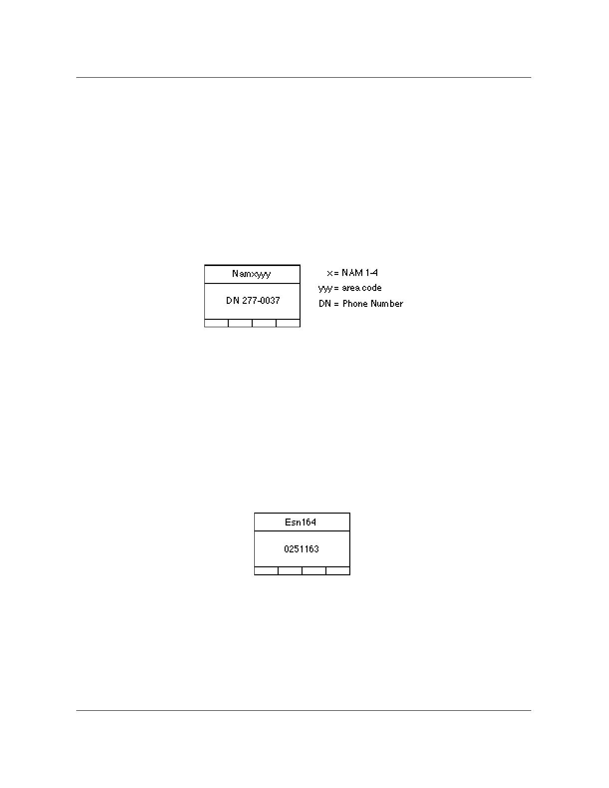
Press the FCN key and then the 0 (zero) key to select a NAM. The display
shows the letters “NAM” and the phone number for NAM1. The “Volume”
arrow keys on the side of the handset can be used to select the other three
NAMs.
To read the ESN (Electronic Serial Number) and to access the contents of
NAM1, enter a six digit security code. The factory default security code is
000000.
When the correct security code is entered, the display shows the (ESN) of the
mobile telephone. Record the ESN number as it is required for datafilling the
CSMINV table.
Note: The numbers shown in the following screen displays are examples
only.
At this point, you have accessed NAM1 and may press the “Volume” arrow
keys to scroll through all of the NAM parameters. Use the CLR key and the
number keys to set the parameters of the NAM that you have selected. After
changing one parameter, you may edit another one by pressing an arrow key
to scroll to the parameter. Press the STO key when you are done with the
selected NAM.
1-14 Equipment operation Nortel Networks Confidential
411-2051-500 Draft 00.01 November 1999
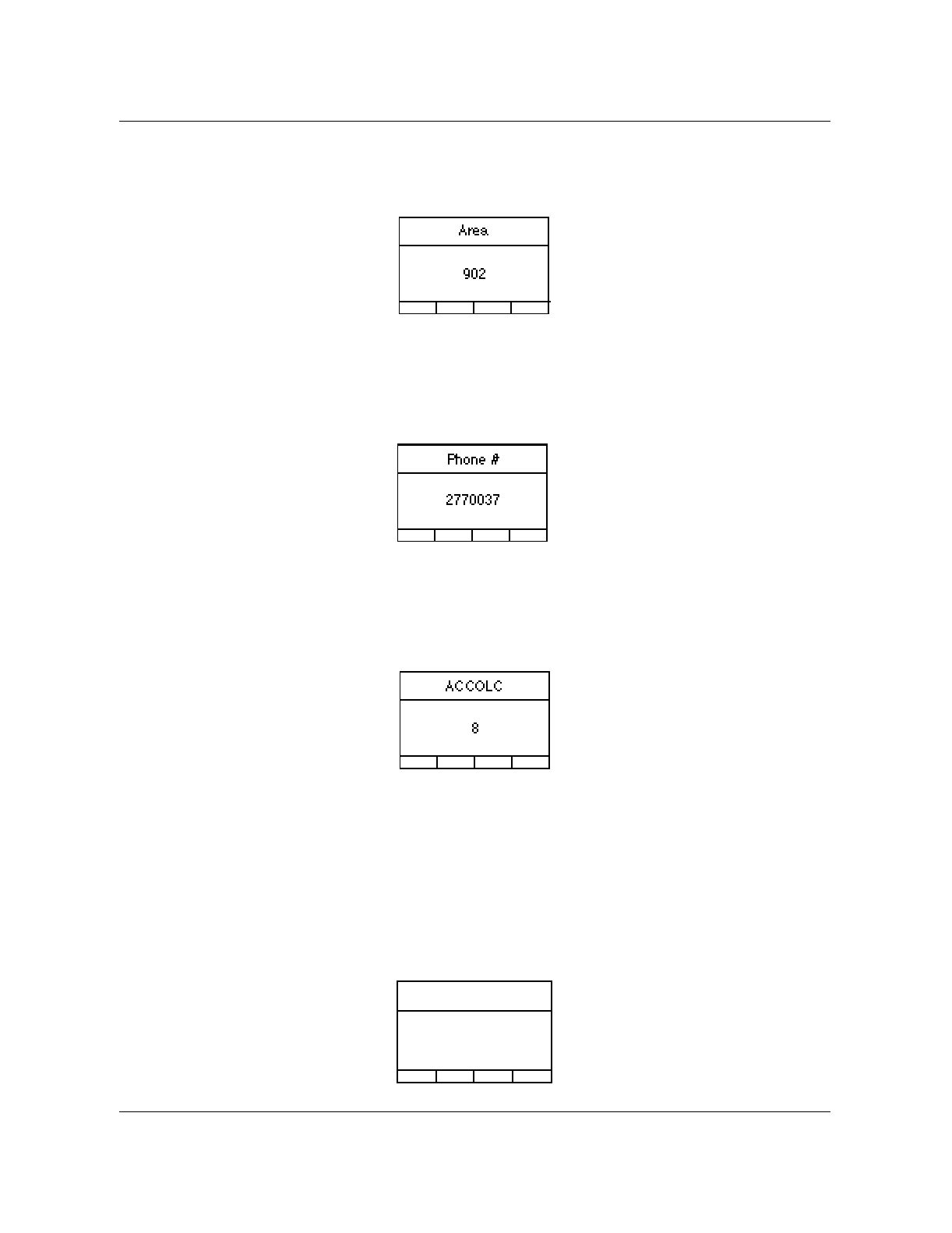
Use the arrow key to scroll to the Area Code display. Enter your three digit
area code.
Use the arrow key to scroll to the Phone Number display. Enter your seven
digit phone number.
Use the arrow key to scroll to the Access Overload Class (ACCOLC) display.
Enter the ACCOLC. The default setting is 10 for the DCSM.
For NAM4 only:
Use the arrow key to scroll to the field ScnDCCH
• Set ScnDCCH to 1 if you want the mobile to scan using the IS-136.1
scanning algorithm (that is, scan for DCCHs) or
• Set ScnDCCH to 0 if you want the mobile to scan using the IS-136.2
scanning algorithm (that is, scan ACCHs only)
ScnDCCH
1
Nortel Networks Confidential DualMode Cell Site Monitor (DCSM) 1-15
Wireless Solutions DualMode 800 Enclosure Maintenance Manual MTX08
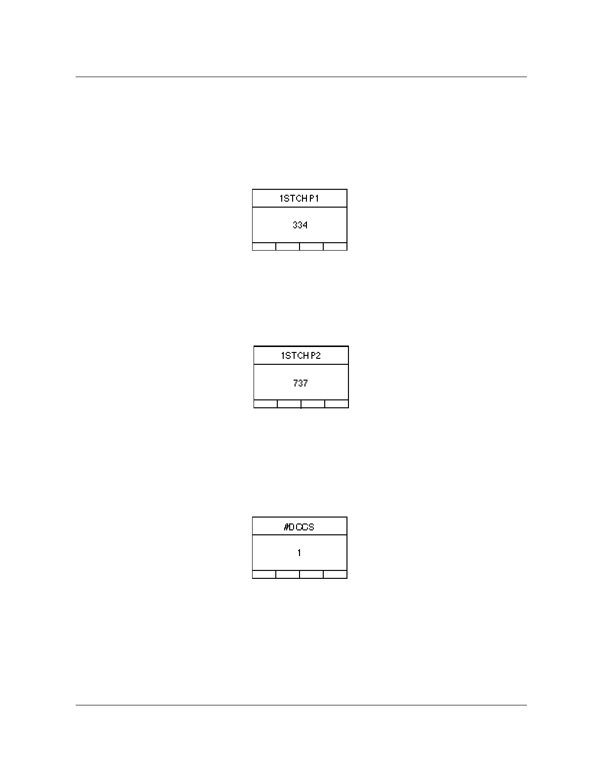
Use the arrow key to scroll to the Primary First Paging Channel (1STCHP1)
display. Enter the Control Channel (CCH) number for your cellular band,
Channel 333 for A system or channel 334 for B system. The CCH must be a
standard CCH although NAM4 can be programmed to use a non-standard
CCH. A non-standard CCH is generally for bench-testing to prevent
interference with local cel1site CCHs. (333 for A, or 334 for B system)
Use the arrow key to scroll to the Secondary First Paging Channel
(1STCHP2) display. Enter the three digit second control channel number of
the cell site, if any. (708 for A, or 737 for B system)
Programming control channels to scan:
NAM4 only
Use the arrow key to scroll to the #DCCS (number of dedicated control
channels) display. Enter the total number of control channels that the DCSM
is assigned to scan (1 to 21 channels).
For NAM4 only:
Use the arrow key to scroll to 1STCHA1 display. Enter the A side primary
control channel (IS-54B and IS-136.2 default 333).

1-16 Equipment operation Nortel Networks Confidential
411-2051-500 Draft 00.01 November 1999
Repeat this step for: 1STCHA2 A side secondary control channel (708*)
1STCHB1 B side primary control channel (334 *)
1STCHB2 B side secondary control channel (737*)
* IS54B and IS-136.2 defaults
Note: These fields define the control channels the DCSM is to use.
For example: range of control channels = STCHAx + (#DCCS + 1)
and/or = 1STCHBx - (#DCCS - 1)
For NAM4 only:
Use the arrow key to scroll to the #DCCHS (number of Digital Control
Channels) display. Enter the total number of control channels that the DCSM
is assigned to scan (1 to 21 channels).
.
For NAM4 only:
Use the arrow key to scroll to the 1st Digital Control Channel (1STDCCH)
display. Enter your 1st DCCH.
#DCCHS
21
1STDCCH
767
Nortel Networks Confidential DualMode Cell Site Monitor (DCSM) 1-17
Wireless Solutions DualMode 800 Enclosure Maintenance Manual MTX08
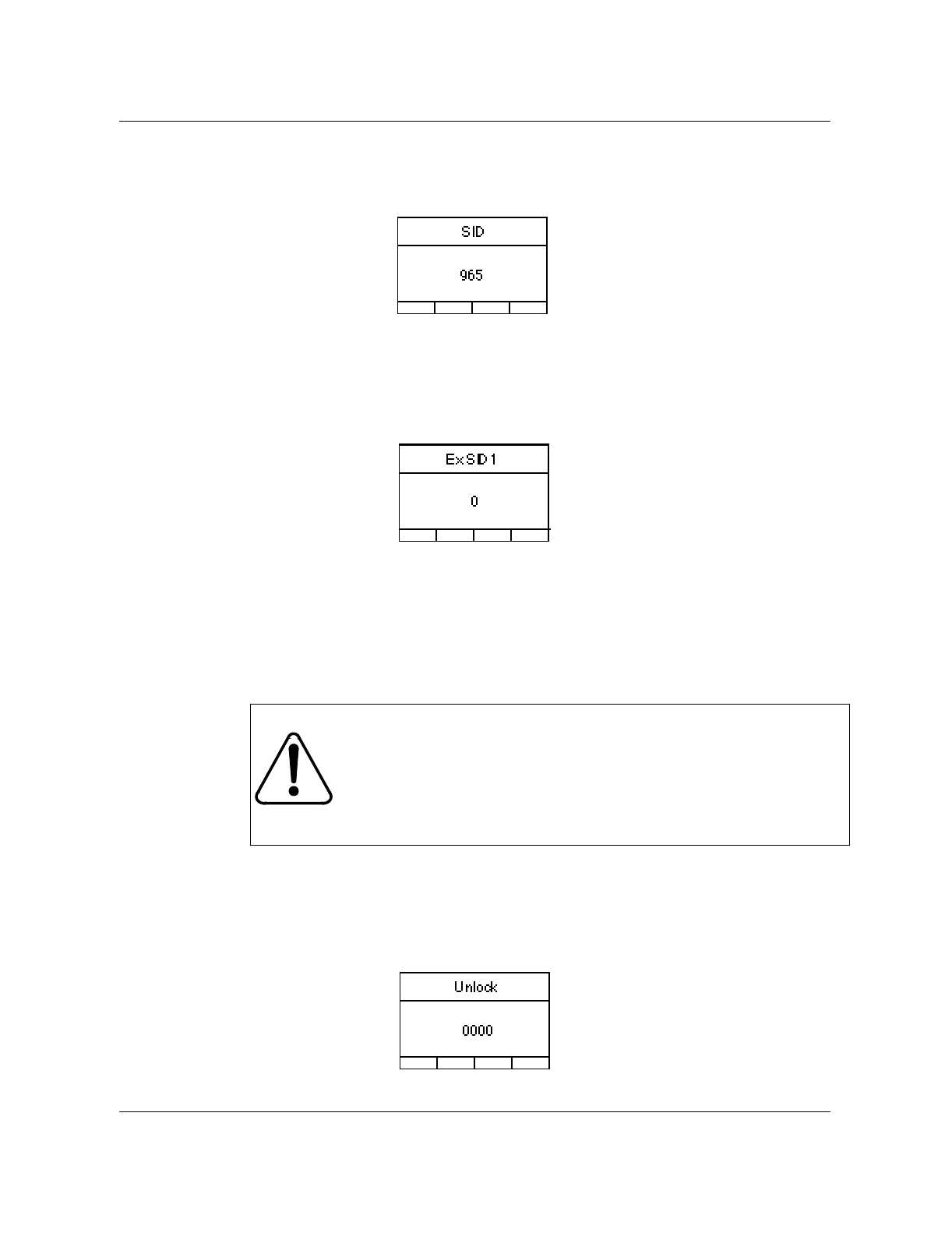
Use the arrow key to scroll to the System ID (SID) display. Enter your System
ID.
Use the arrow key to scroll to the Extended System ID 1 display (Ex SID1). If
the factory default does not read zero then enter zero in this field.
Repeat this step for the other Extended System IDs (Ex SID2-Ex SID8).
Use the arrow key to scroll to the Unlock Code display. Enter your four digit
Unlock Code. The factory default is 0000.
Note: Nortel Networks recommends that unless under management
directive, the Unlock and Security codes not be changed from their
defaults.
CAUTION
Whenever you enter a new Unlock Code or Security Code,
make sure that you have recorded the new code. There is no
way you can unlock the mobile or enter the NAM again
without entering the correct Unlock Code or Security Code.
1-18 Equipment operation Nortel Networks Confidential
411-2051-500 Draft 00.01 November 1999
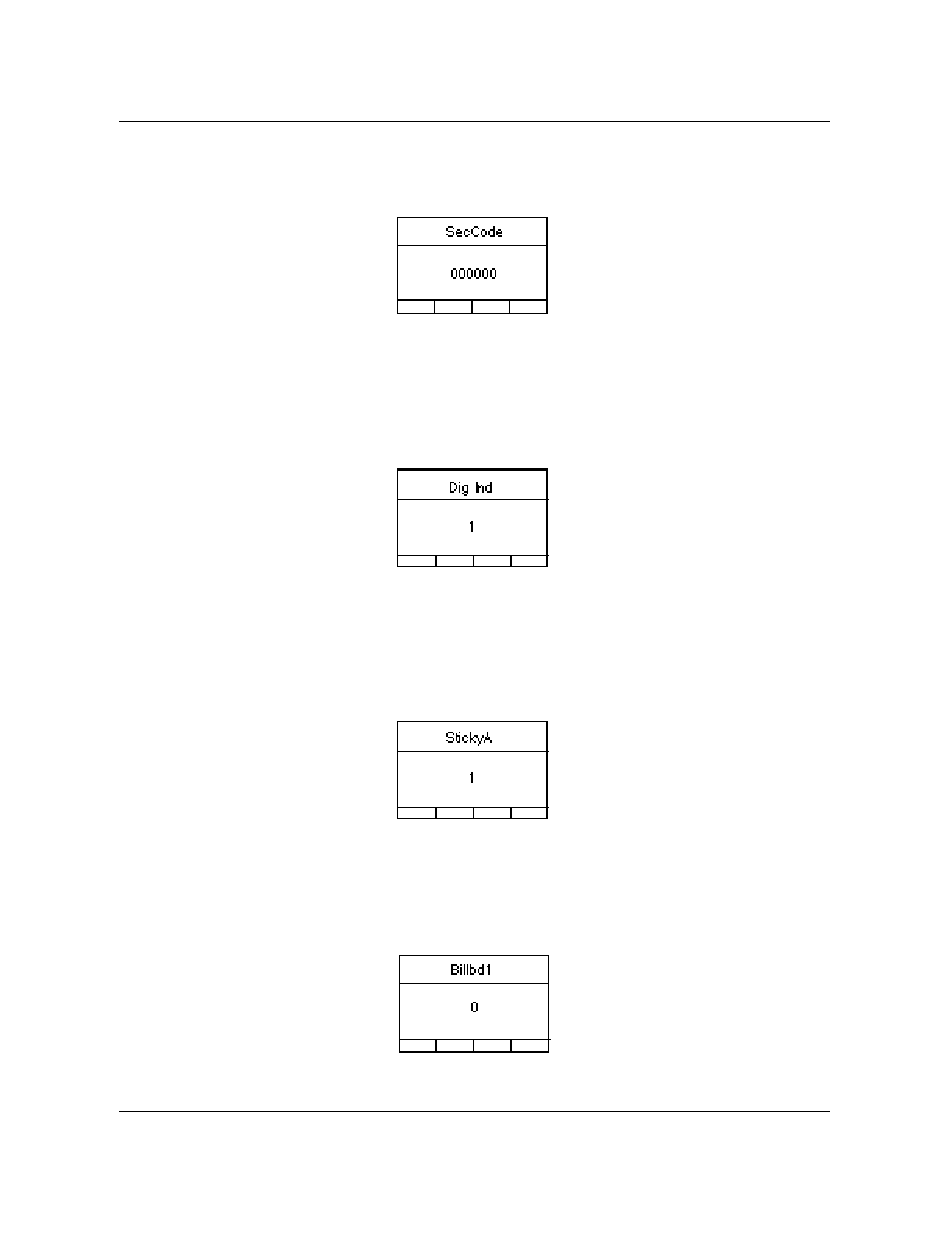
Use the arrow key to scroll to the Security Code (SecCode) display. Enter
your six digit Security Code. The factory default is 000000.
Use the arrow key to scroll to the Digital Indicator display (Dig Ind).
Note: In the DCSM applications, always enter a 1 to allow the mobile to
indicate if it is in Digital mode.
Use the arrow key to scroll to the Sticky Analog display (StickyA).
Note: In the DCSM application, always enter a 0 to keep the mobile in
analog mode and preventing it from entering the digital mode state.
For NAM1 only:
Use the arrow key to scroll to Billboard 1 (Billbd 1). Enter a zero in this field.
Repeat this step for the BillBd 2 field.

Nortel Networks Confidential DualMode Cell Site Monitor (DCSM) 1-19
Wireless Solutions DualMode 800 Enclosure Maintenance Manual MTX08
Use the arrow key to scroll through the NAM and verify that all the values
have been entered correctly. Press STO key to store all the values into volatile
memory that you have entered.
Press the reset button on the rear panel of the DCSM to reset the unit. You can
also perform a BSY and RTS to reset the DCSM. You have programmed
NAM's non-volatile memory when the self-test is completed.
NAM 4 must be programmed as well if only one telephone number is
assigned to the DCSM. Nortel Networks recommends that you also load the
three remaining NAMs (NAMs 2,3 and 4) with the same information to
prevent from inadvertently selecting a vacant NAM.
Repeat the same programming procedure by using the FCN key and the 0
(zero) key to get the NAM display. Use the arrow key to select one of the
three remaining NAMs. Program each NAM.
1-20 Equipment operation Nortel Networks Confidential
411-2051-500 Draft 00.01 November 1999
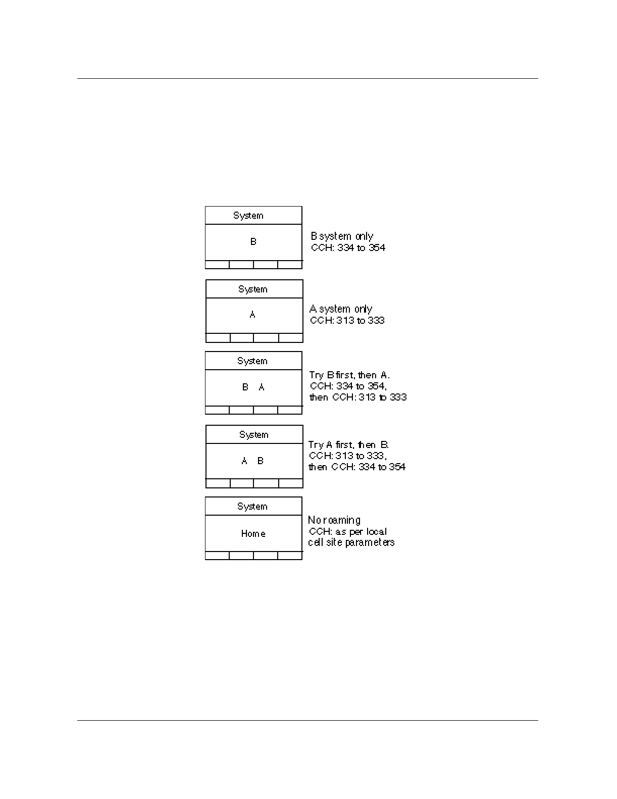
Programming the system selection
When all the NAMs have been programmed, enter the system selection for
the DCSM in your service area. Press the FCN key and then the 1 key. Use the
arrow key to scroll through the system selection options. When the system of
your service area appears (consistent with your Primary First Paging Channel,
1STCHP1, in NAM4), stop scrolling. Press the STO key to confirm your
selection and place it into memory.
Note: Making a system selection inconsistent with your 1STCHP1 could
prevent calls from being made and cause the “Roam” indicator on the
display to blink.
Configuration of the mobile cellular telephone is now complete and the phone
can now be used to originate and answer calls.

Nortel Networks Confidential DualMode Cell Site Monitor (DCSM) 1-21
Wireless Solutions DualMode 800 Enclosure Maintenance Manual MTX08
Operating the mobile
When all the NAMs have been programmed and the system selection has
been selected, the Mobile Unit is ready for operation.
Receiving a call
When the phone rings, lift the handset from the hang up cradle and press the
SND key to answer the call.
Note: If the phone is locked, or you are accessing functions or storing/
recalling a number when the phone rings, you can still answer the call by
pressing the SND key.
Placing a call
Enter the telephone number you want to call and press the SND key.
Ending a call
Press the END key to end a call.
Note: Returning the handset to the hang up cradle without pressing the
END key will not end a call.
1-22 Equipment operation Nortel Networks Confidential
411-2051-500 Draft 00.01 November 1999
Transmit Receive Unit (TRU)
The Transmit Receive Unit (TRU) provides two methods for accessing the
Operation, Administration, and Maintenance (OA&M) functionality, the front
panel display interface and the AMPS/TDMA Terminal Interface. The front
panel display provides operating parameters and status information; the
Terminal Interface acts as a user-friendly interface to TRU command, control,
and monitoring functions.
The operating parameters and status information on the front panel display
are also available through the terminal interface by using the QUERY FAULT
command in the command line mode. This contains all of the necessary
information for proper OA&M functions of the TRU.
The front panel display interface
The front panel display on the TRU provides operating parameter information
for the technician to properly administer the TRU.
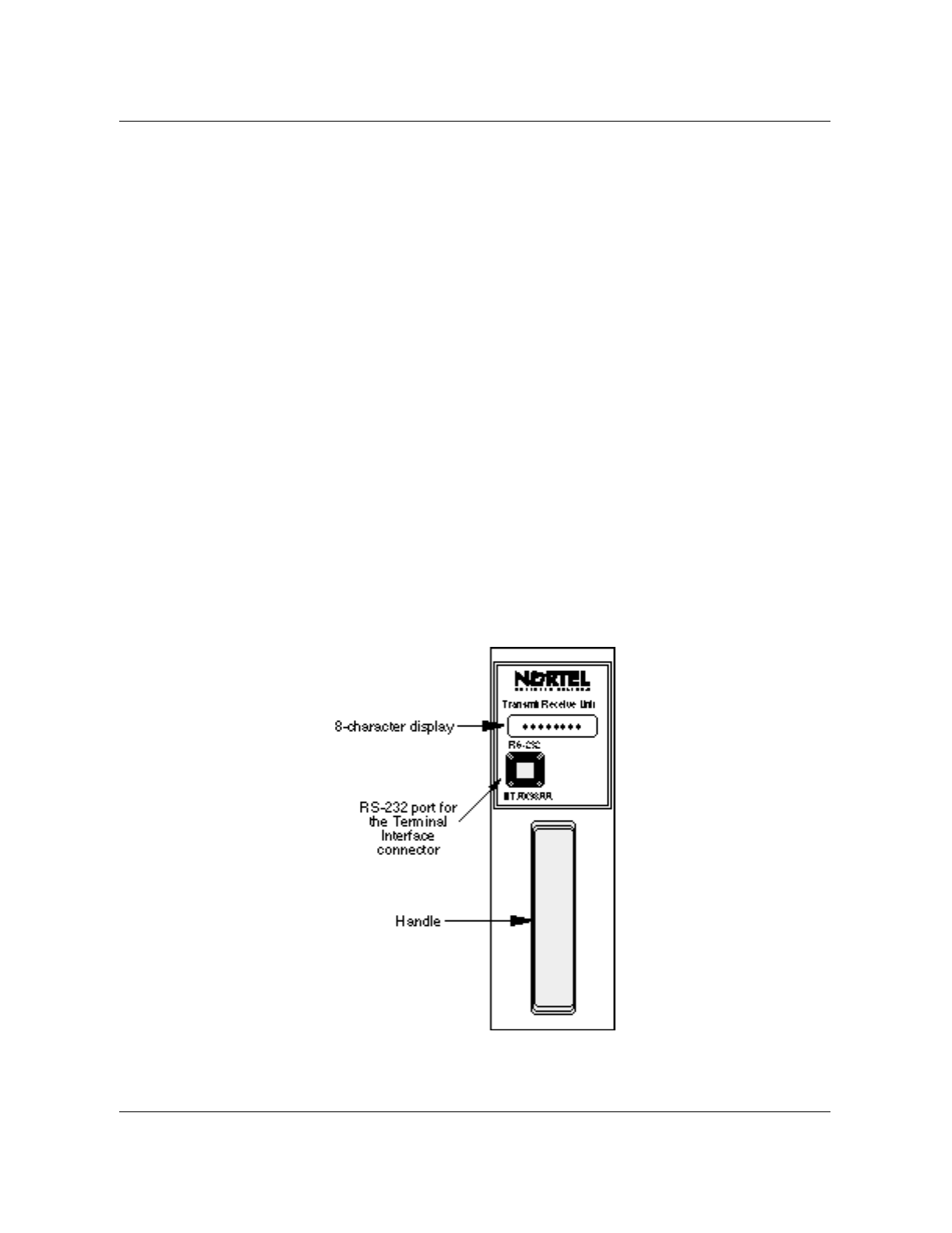
TRU2 (NTAX98AA) front panel display interface
The front panel display interface for the TRU2 (NTAX98AA), as shown in
Figure 1-6, consists of an eight-character LED display of current status
information.
Figure 1-6
Front panel layout of the TRU2 (NTAX98AA)
Nortel Networks Confidential Transmit Receive Unit (TRU) 1-23
Wireless Solutions DualMode 800 Enclosure Maintenance Manual MTX08
• The first three characters on the display show the current personality of
the TRU:
Display Personality
AVC Analog Voice Channel
ACC Analog Control Channel
ALR Analog Locate Receiver
DCC Digital Control Channel
MDS Mobile Data Base Station
TTC TDMA (digital) Traffic Channel
TLR TDMA (digital) Locate Receiver
• The next character on shows an asterisk (*) if the TRU is currently
transmitting. Otherwise, it is left blank.
• The last four characters show the current channel number or, if the TRU is
not selected, ROMIDLE is displayed.
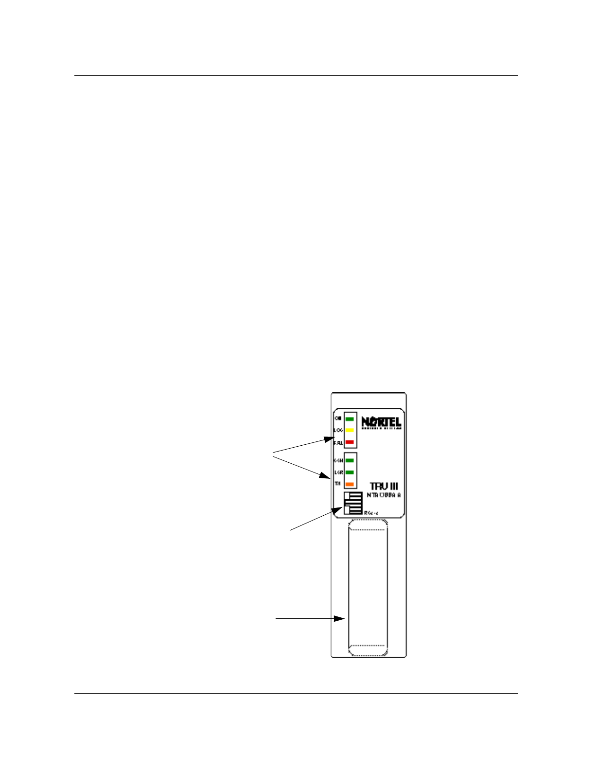
TRU3 (NTAW99AA) front panel display interface
The front panel display interface for the TRU3 (NTAW99AA), as shown in
Figure 1-7, consists of six LEDs. The top three LEDs show the operational
status of the TRU. The bottom three LEDs show the personality status of the
TRU.
Figure 1-7
Front panel layout of the TRU3
RS-232 port for the
Terminal Interface
connector
Handle
Status LEDs

1-24 Equipment operation Nortel Networks Confidential
411-2051-500 Draft 00.01 November 1999
Table 1-1 shows the various transitions in LED state that may be observed
during operation.
Table 1-1
Transitions in the TRU3 LED state
State Status LED Descri
p
tion/Action
ON LOS FAIL CCH LCR TX
1 Power-up
(
LED check
)
Flash Flash Flash Flash Flash Flash
LEDs flash on and off for approximately
1 second, then radio
g
oes to state 2.
2Dia
g
nostics Off Last
state Last
state On On Off Radio is not in service. It performs a
series of hardware diagnostic tests that
run for approximately 12 seconds. If all
tests pass, radio goes to state 3;
otherwise, it goes to state 5.
3 ROM-idle On Last
state Last
state On On Off If the radio in this state is not put into
service in one minute, it resets itself
and returns to state 2. The radio
transitions between states 2 and 3 until
it is put into service (state 6), loading
begins (state 4), or a Hard Reset
command is received from the MTX
(state 2).
4 Loadin
g
On Off Off
Flash Flash
Off The ON LED is on and the CCH and
LCR LEDs flash durin
g
the loadin
g
period. When loadin
g
is complete, radio
returns to state 2.
5 Idle fault Off Off On Off Off Off The radio is in this state when a
hardware dia
g
nostic test fails before
the radio is put into service. When the
radio is in this state, perform the
followin
g
:
(
a
)
Re-seat the radio into its slot a
g
ain
(
or to another slot
)
to identif
y
if the fail
was caused b
y
a power suppl
y
g
litch or
some other transient event.
(
b
)
If the fault is cleared, the FAIL LED
turns off, the ON, CCH and LCR LEDs
turn on and the radio proceeds to state
2.
(
c
)
If the FAULT LED remains on,
replace the radio and return it to
y
our
Customer Service Office
(
CSO
)
for
repair.
- continued -

Nortel Networks Confidential Transmit Receive Unit (TRU) 1-25
Wireless Solutions DualMode 800 Enclosure Maintenance Manual MTX08
Note 1: Loss-of-service conditions which are not detected by the radio,
such as excessive SWERRs, do not cause the yellow LED to turn on
directly. However, if the ICP chooses to close the signalling connection to
the radio, the yellow LED will be activated indirectly and further
6 In-service
—DCCH or
2T+C
On Off Off On Off On Durin
g
normal operation, the TX LED
turns on whenever the radio’s
transmitter is active.
Radio remains in this state until one of
the followin
g
s happens:
—external failure detected, radio
g
oes
to state 7
—internal hardware failure detected,
radio
g
oes to state 8
—radio taken out of service b
y
the MTX
(
SYBSY
)
or b
y
an operator
(
MANB
)
,
radio
g
oes to state 2
In-service
—TTC
(
transmitter
active
)
On Off Off Off Off On
In-service
—TTC
(
transmitter
inactive
)
On Off Off Off Off Off
7LOS On On
(
Note
1
)
Off Last
state Last
state Last
state
(
Note
2
)
This state indicates that a failure
outside the radio has occurred. Typical
loss of service conditions include: PA
fault, Link Access Protocol-D (LAPD)
link disconnection, or a loss of
connection to the Digital Signal
Processing Module (DSPM). The MTX
will take the radio out of service (state
2) once the LOS condition is reported
with the exception of loss connection to
DSPM. The radio is reported as in-
service trouble state. Service is
restored when the connection to the
DSPM is re-established.
8Fault OffOffOn
(
Note
3
)
Off Off Off This state indicates that an internal
hardware fault is detected. The MTX
will take the radio out of service (state
2) once the fault is reported. The fault is
reported to the MTX as an MTX105 log.
Refer to the
DualMode Radio Unit
Troubleshooting Guide
, 411-2131-166,
for more information.
- End -
Table 1-1
Transitions in the TRU3 LED state (continued)
State Status LED Descri
p
tion/Action
ON LOS FAIL CCH LCR TX
1-26 Equipment operation Nortel Networks Confidential
411-2051-500 Draft 00.01 November 1999
troubleshooting will be required to isolate the exact cause of the loss of
service.
Note 2: In general, the TX LED is off (radio taken off-the-air) when the
radio is in the loss-of-service or radio-failure states. The only exception is
when the radio is operating in the fractional DCCH (2T+C) state and there
is a loss of connection to the DSPM. In this case, the loss-of-service
condition applies because the traffic channels within the radio are
unusable. However, the TX LED is on because the DCCH within the radio
is still active.
Note 3: When a fault is detected, the radio is taken SYSBSY and any
attempt to return the radio into service is expected to fail. It may be
necessary to replace the radio before proper operation can be achieved.
The Terminal Interface
The terminal interface, connected to the TRU is for the purposes of
installation, maintenance, tests, and status query, is an ASCII terminal. The
Operation, Administration and Maintenance (OA&M) commands are entered
by way of a VT100 (or compatible) terminal connected to the RS-232
interface on the front panel of the TRU. This allows maintenance, test, query,
and measurement functions to be performed without requiring the TRU to be
connected to the rest of the DMS-MTX* system.
Commands are typed into the terminal to set operating parameters and
perform control, maintenance, and status query functions. It is typically used
to bring the unit on air during installation and commissioning. There are no
switches, jumpers, or adjustable hardware elements within the TRU that need
to be accessed by the user.
All TRU operating parameters are controlled either from the ASCII terminal
or from a Maintenance and Administration Position (MAP*) terminal at the
MTX switch as part of call processing. The control from the MAP terminal is
called the Remote Radio Interface (RRIF) feature. Refer to the Remote Radio
InterFace Reference, 411-2131-115, for the RRIF commands.
Note: Not all OA&M commands are available for the TRU3 through
RRIF. The TRU3 does not support RRIF Layer 2, VBER, or RF
measurements in MTX08.
CAUTION
Service interru
p
tion
Never put a TRU into the terminal interface mode when the
TRU is in an active call processing state. The call in progress
will be dropped.

Nortel Networks Confidential Transmit Receive Unit (TRU) 1-27
Wireless Solutions DualMode 800 Enclosure Maintenance Manual MTX08
The terminal interface can be operated in command line mode or in the more
convenient fullscreen monitor mode. The basic commands, with the same
functionality, are available in the command line mode as well as in the
fullscreen mode.
The AMPS/TDMA Fullscreen Monitor
The AMPS/TDMA Fullscreen Monitor is the primary user interface to the
DRU's OA&M capabilities. Two modes of operation are available; analog
(AMPS) mode and digital (TDMA) mode. The primary purpose of the
Fullscreen Monitor is to provide a mean for quickly commissioning a DRU in
a cell site. Additionally, it provides user-friendly access to the DRU's OA&M
test and maintenance functions so that problems in the DRU or the mobile can
be detected, diagnosed, and remedied. The Fullscreen Monitor is intended for
use on a DRU not in an active call processing state.
Note: The TRU3 does not support AMPS mode. However, the commands
for AMPS operation can still be entered in both the command line mode
or the fullscreen mode.
Fullscreen monitor setup
The terminal interface can be operated in command line mode or in the more
convenient fullscreen monitor mode. The basic commands, with the same
functionality, are available in the command line mode as well as in the
fullscreen mode.
The fullscreen monitor is the primary user interface to the OA&M capabilities
of the DRU. Two modes of operation are available; analog (AMPS) mode and
digital (TDMA) mode.
Connect a VT100 (or equivalent) terminal to the RS-232 port on the front panel
of the Transmit Receive Unit (TRU). By pressing the “Break” key on the
terminal keyboard, you can access the command line mode. The terminal will
display the following:
For the TRU 2:
TRU Terminal Interface
(C) Copyright 1990-1996 Bell Northern Research, Inc.
>
For the TRU3:
TRU-III Terminal Interface
(C) Copyright 1996-97 Nortel
>

1-28 Equipment operation Nortel Networks Confidential
411-2051-500 Draft 00.01 November 1999
To enter the fullscreen mode, at the command line prompt (>), type in the
commands:
>SET LT OFF
>SET FS ON
The SET LT OFF command disables the LAPD timeout. If the TRU detects
loss of the LAPD link, it resets itself after 10-12 seconds. With the LAPD
timeout set off, the TRU does not reset, which is necessary for stand alone
testing.
The SET FS ON command clears the existing display and invokes the
fullscreen display in the AMPS mode. In the fullscreen monitor, the OA&M
commands are displayed and selected by their alphabetic code. The results of
each OA&M command are displayed at specific screen locations.
Figure 1-8 shows the fullscreen displays for the TRU2 and Figure 1-9 shows
the fullscreen for the TRU3. Table 1-2 shows a summary of the fullscreen
commands and these commands are explained in Table 1-3. Table 1-4 to Table
1-6 show and explain the command line mode commands.
The terminal screen is divided horizontally into a status area and a command
area. The bottom line of the terminal display is used as the command area;
you may enter the appropriate letter representing the command. Directly
above the command area is the output message line where status and output
messages, such as selection parameters and error messages, are displayed.
On-line help
Interfacing with the Fullscreen Monitor is simplified by the availability of on-
line help. The user may type “HELP” or “?” in response to any prompt. A brief
paragraph describing the function of the DRU terminal interface is displayed.
Several on-line help categories are available. Each help category contains a
brief, one-line description of each command in that category. The following
categories of help commands are available:
• HELP HELP Lists help categories
• HELP MTCE Lists maintenance commands
• HELP TESTS Lists test commands
• HELP MSR List measurement and query commands
• HELP MONITOR List commands within the monitor subsystem
Nortel Networks Confidential Transmit Receive Unit (TRU) 1-29
Wireless Solutions DualMode 800 Enclosure Maintenance Manual MTX08
Figure 1-8
Fullscreen display for the TRU2
DRU statusCommand menuOutput messageCommand prompt
DRU statusCommand menuOutput messageCommand prompt
AMPS Mode
TDMA Mode
---------TRU TERMINAL INTERFACE (C)1990,1991 Northern Telecom, Inc.-----------
Load: TRU2AT79 ROM: RDRUAB04 EEPROM: Passed HW Ver: rar S/N: 531DDERA
PA FW: -------- PA HW: ---- PA PEC: -------- PA S/N: ---------------
AMPS STATUS
Channel: ---- PA: off SAT TX: 6000 ( on) Antenna Port A: 1 B: 4
Synth Lock: NO TxPwrIndex: 0 Compandor: on Antenna Path: DIV
PA Alarm: off TxPwrStep: 4.00 Loopback: BCH Audio Sens RX: -18.0
Audio: off MaxTxPwr: 27.00 Tone Gen: off Audio Sens TX: -18.0
------------------------------Signal Readings-----------------------------------
RX RSSI: Antenna Port: 1 2 3 4 5 6
RX SAT: RSSI Offset : 0.0 0.0 0.0 0.0 0.0 0.0
RX ST: RSSI : - - - - - -
----------------------------------COMMANDS--------------------------------------
A) TDMA Mode G) SAT Transmit M) Set Antenna Port S) Test TRU display
B) Set Channel H) Change SAT N) Set Path T) Set Audio Sens
C) PA on/off I) Tone Gen O) Set RSSI Offset U) Set TXPOWSTEP
D) PA LED on/off J) Loopback P) Detect SAT,ST,RSSI X) Exit
E) Set TXPOWIDX K) Compandor Q) Detect ALL RSSI Y) Restart TRU
F) Set MAXTXPOW L) Wideband Data R) RX/TX Audio
--------------------------------------------------------------------------------
Screen Refresh completed.
>
---------TRU TERMINAL INTERFACE (C)1990,1991 Northern Telecom, Inc.-----------
Load: TRU2AT79 ROM: RDRUAB04 EEPROM: Passed HW Ver: rar S/N: 531DDERA
PA FW: -------- PA HW: ---- PA PEC: -------- PA S/N: ---------------
TDMA STATUS
Channel: ---- PA: off DVCC: 01 Antenna Port A: 1 B: 4
Synth Lock: NO TxPwrIndex: 0 Slot: 1 Antenna Path: DIV
PA Alarm: off TxPwrStep: 4.00 Loopback: BCH
MaxTxPwr: 27.00 Tone Gen: off
------------------------------Signal Readings-----------------------------------
RX RSSI: Antenna Port: 1 2 3 4 5 6
RX DVCC RSSI Offset : 0.0 0.0 0.0 0.0 0.0 0.0
( ) : RSSI : - - - - - -
----------------------------------COMMANDS--------------------------------------
A) AMPS Mode F) Set MAXTXPOW M) Set Antenna Port S) Test TRU display
B) Set Channel G) Set DVCC N) Set Path T) Standalone TX
C) PA on/off H) Set Slot O) Set RSSI Offset U) Set TXPOWSTEP
D) PA LED on/off I) Tone Gen P) Detect DVCC,RSSI X) Exit
E) Set TXPOWIDX J) Loopback Q) Detect ALL RSSI Y) Restart TRU
--------------------------------------------------------------------------------
Screen Refresh completed.
>
1-30 Equipment operation Nortel Networks Confidential
411-2051-500 Draft 00.01 November 1999
Figure 1-9
Fullscreen display for the TRU3
DRU statusCommand menuOutput messageCommand prompt
DRU statusCommand menuOutput messageCommand prompt
AMPS Mode
TDMA Mode
---------TRU TERMINAL INTERFACE (C)1996,1997 Northern Telecom, Inc.-----------
Load: TRU31W40 Boot: BDRUAA01 CRC: Passed HW Ver: rq1 S/N: 530d8d0a
PA FW: -------- PA HW: 5765 PA PEC: nthx51aa PA S/N: nntm61015ah7--
AMPS STATUS
Channel: 367 PA: on SAT TX: 6000 (off) Antenna Port A: 1 B: 4
Synth Lock: yes TxPwrIndex: 0 Compandor: off Antenna Path: DIV
PA Alarm: off TxPwrStep: 4.00 Loopback: off Audio Sens RX: -28.0
Audio: off MaxTxPwr: 47.00 Tone Gen: off Audio Sens TX: -16.0
------------------------------Signal Readings-----------------------------------
RX RSSI: Antenna Port: 1 2 3 4 5 6
RX SAT: RSSI Offset : 0.0 0.0 0.0 0.0 0.0 0.0
RX ST: RSSI : - - - - - -
----------------------------------COMMANDS--------------------------------------
A) TDMA Mode G) SAT Transmit M) Set Antenna Port T) Set Audio Sens
B) Set Channel H) Change SAT N) Set Path U) Set TXPOWSTEP
C) PA on/off I) Tone Gen O) Set RSSI Offset X) Exit
D) PA LED on/off J) Loopback P) Detect SAT,ST,RSSI Y) Restart TRU
E) Set TXPOWIDX K) Compandor Q) Detect ALL RSSI
F) Set MAXTXPOW L) Wideband Data R) RX/TX Audio
--------------------------------------------------------------------------------
Screen Refresh completed.
>
---------TRU TERMINAL INTERFACE (C)1996,1997 Northern Telecom, Inc.-----------
Load: TRU31W40 ROM: BDRUAA01 CRC: Passed HW Ver: rq1 S/N: 530d8d0a
PA FW: -------- PA HW: 5765 PA PEC: nthx51aa PA S/N: nntm61015ah7--
TDMA STATUS
Channel: 367 PA: off DVCC: 01 Antenna Port A: 1 B: 4
Synth Lock: yes TxPwrIndex: 0 Slot: 1 Antenna Path: DIV
PA Alarm: off TxPwrStep: 4.00 Loopback: off
MaxTxPwr: 47.00 Tone Gen: off
------------------------------Signal Readings-----------------------------------
RX RSSI: Antenna Port: 1 2 3 4 5 6
RX DVCC RSSI Offset : 0.0 0.0 0.0 0.0 0.0 0.0
( ) : RSSI : - - - - - -
----------------------------------COMMANDS--------------------------------------
A) AMPS Mode F) Set MAXTXPOW M) Set Antenna Port T) Standalone TX
B) Set Channel G) Set DVCC N) Set Path U) Set TXPOWSTEP
C) PA on/off H) Set Slot O) Set RSSI Offset X) Exit
D) PA LED on/off I) Tone Gen P) Detect DVCC,RSSI Y) Restart TRU
E) Set TXPOWIDX J) Loopback Q) Detect ALL RSSI
--------------------------------------------------------------------------------
Screen Refresh completed.
>

Nortel Networks Confidential Transmit Receive Unit (TRU) 1-31
Wireless Solutions DualMode 800 Enclosure Maintenance Manual MTX08
Fullscreen commands
Table 1-2 lists a set of the fullscreen commands. Some commands are only
applicable to the TRU in either the analog or digital mode; others are applicable
only when the TRU is in a particular state. Using such a command when the
TRU is not configured correctly results in the error message below:
That function is not available in the DRU's current state.
A command is entered on the command line at the > prompt. You must press
the “Return” key to execute the command. For some commands, additional
parameters need to be entered and a prompt will appear on the message line.
Enter the appropriate parameter and press the “Return” key to execute the
command. Only one command may be executed at a time.
Table 1-2
TRU Fullscreen command summary
Code AMPS Mode TDMA Mode
A Chan
g
e screen to TDMA mode displa
y
Chan
g
e screen to AMPS mode displa
y
B Set Channel Set Channel
C Set PA on/off Set PA on/off
D Set PA LED on/off Set PA LED on/off
E Set TXPOWIDX Set TXPOWIDX
F Set MAXTXPOW Set MAXTXPOW
G SAT Transmit Set DVCC
H Chan
g
e SAT Set SLOT
I Set Tone Gen Set Tone Gen
J Set Loopback Set Loopback
K Set Compandor —
L Set Wideband Data —
M Set Antenna Port Set Antenna Port
N Set Path Set Path
O Set RSSI Offset Set RSSI Offset
P Detect SAT/ST/RSSI Detect DVCC/RSSI
Q Detect ALL RSSI Detect ALL RSSI
R Set Rx/Tx Audio —
S Test TRU Displa
y
Test TRU Displa
y
T Set Audio Sens Standalone TX
U Set TXPOWSTEP Set TXPOWSTEP
XExit Exit
Y Restart TRU Restart TRU

1-32 Equipment operation Nortel Networks Confidential
411-2051-500 Draft 00.01 November 1999
A complete description of the fullscreen commands is given in Table 1-3. This
table is broken into five groups according to the functions of the commands:
• Configuration functions for TRU operating parameters
• Transmit functions for TRU transmit status
• Receive functions for TRU receive status
• AMPS mode functions for functions available in AMPS mode only
• TDMA mode functions for functions available in TDMA mode only
Table 1-3
TRU Fullscreen commands
Confi
g
uration functions
(
available to both the AMPS and the TDMA modes
)
:
Code Command Status Action/Initial Value
A Set Mode AMPS
TDMA To
gg
les between the AMPS mode displa
y
and the TDMA
mode displa
y
.
B Set Channel 0000 Sets the current channel and updates the Channel field on
the displa
y
. If the TRU S
y
nthesizer was able to lock to the
specified channel, the S
y
nth Lock field displa
y
s "YES";
otherwise, the Channel field displa
y
s "----" and the S
y
nth
Lock field displa
y
s "NO".
D Set PA LED on/off Turns the alarm LED on the front panel of the MCPA on or
off. The status is shown in the PA Alarm field.
I Set Tone
Gen BCH
RF
Off
Turns on either the tone
g
eneration
(
1004 Hz
)
on the B-
channel to the MTX, the RF tone
g
eneration
(
1 kHz
)
on air,
or turns off the tone
g
eneration. The status is shown in the
Tone Gen field.
J Set
Loopback BCH
RF
Off
Sets either the B-Channel Audio Loopback
(
to MTX
)
, the
RF Loopback
(
to mobile
)
, or Off
(
no Loopback
)
. The status
is shown in the Loopback field.
S Test Displa
y
(
not available
for TRU3
)
— Verifies the TRU's 8-character LED displa
y
b
y
alternatel
y
showin
g
the followin
g
three patterns on the LED displa
y
until the “Return” ke
y
is pressed:
00000000
********
........
X Exit — Leaves fullscreen monitor mode, clearin
g
the screen and
returnin
g
to command line mode.
Y Restart TRU W
CExecutes either a ROM level reset
(
C = COLD
)
or a
FLASH level restart
(
W = WARM
)
. You are prompted for
the t
y
pe of restart to be performed.
Note:
This will restart the DRU and force an exit from the
fullscreen monitor mode.
C Set PA on/off on/off Turns the TRU transmitter on or off. The status is shown in
the PA field.
- continued -

Nortel Networks Confidential Transmit Receive Unit (TRU) 1-33
Wireless Solutions DualMode 800 Enclosure Maintenance Manual MTX08
Table 1-3
TRU Fullscreen commands
(
continued
)
Use the three TRU Power commands according to the following relationship
when adjusting the TRU output power:
TRU Output Power = MAXTXPOW - (TXPOWIDX x TXPOWSTEP)
Example: If you require an output power of 15.75 dBm at the TRU output, you can use
either one of the following TRU power settings to obtain that output power.
Transmit functions
(
available to both the AMPS and the TDMA modes
)
:
Code Command Status Action/Initial Value
E Set
TXPOWIDX 0..7 Sets the current TRU power level attenuation number. The
TRU has maximum output power when power level is set at
“0”
(
no attenuation
)
. The status is shown in the Power Level
or TxPwrIndex field.
Note:
Nortel Networks recommends that
y
ou set the power
level at “0” unless otherwise specified as a site re
q
uirement.
F Set
MAXTXPOW -1.0 dBm to
27.0 dBm
Note:
These
values are for
NO PATYPE
used in Urban.
Defines the maximum power level
(
dBm
)
which maps to an
Attenuation Level number of “0” and updates the TRU
Power or MaxTxPwr field. Due to the nature of this
command, it is not available if
y
ou have not previousl
y
set
the TRU power level.
Note:
If the TRU transmitter is on
(
C command
)
and the
power level is set
(
E command
)
, the TRU output power
chan
g
es immediatel
y
when this command is entered.
U Set
TXPOWSTEP 1..4 Sets the current MCPA power step size number
(
1.00 dB to
4.00 dB in 0.25 dB steps
)
. The status is shown in the Power
Step or TxPwrStep field.
Note:
Nortel Networks recommends that
y
ou set the power
step size at “4” unless otherwise specified as a site
re
q
uirement.
- continued -
TRU Power Settin
g
sTRU
Out
p
ut
Max Power/
MAXTXPOW Power Level/
TXPOWIDX Power Ste
p
size/
TXPOWSTEP Power
(
in dBm
)
1 15.75 0
(
no attenuation
)
4.00
(
default
)
15.75 -
(
0 x 4.00
)
= 15.75
2 27.00
(
default
)
3 3.75 27.00 -
(
3 x 3.75
)
= 15.75
3 27.00
(
default
)
5 2.25 27.00 -
(
5 x 2.25
)
= 15.75

1-34 Equipment operation Nortel Networks Confidential
411-2051-500 Draft 00.01 November 1999
Table 1-3
TRU Fullscreen commands
(
continued
)
Table 1-3
TRU Fullscreen commands
(
continued
)
Receive functions
(
available to both the AMPS and the TDMA modes
)
:
Code Command Status Action/Initial Value
M Set Antenna
Port
(
1 or 2 or 3
)
(
4 or 5 or 6
)
Selects antenna ports to use on path A and B. The
Antenna Port field will show:
Port A: 1, 2 or 3
Port B: 4, 5 or 6
Note
: Onl
y
1 and 4 can be selected in Omni cell sites.
N Set Path A
B
DIV
Selects the antenna path. The status is shown in the
Antenna Path field. DIV indicates diversit
y
switchin
g
between paths A and B.
O Set RSSI
Offset xx.x
Parameters
for detector,
ant1, ant2
and ant3
must be
entered.
Sets the 3 RSSI Offsets
(
MCGAIN
)
for the ports on the
specified antenna path. Input values are limited to the
ran
g
e -100 to +100; however, the offsets should be kept to
± 5 dB to keep RSSI values between -130 dBm and -30
dBm.
(
See the RSSI Offset tests in Chapter 11.
)
Q Detect All
RSSI —
Si
g
nal
readin
g
area
displa
y
s:
-000.0
Constantl
y
measures RSSI detected on all the six antenna
ports until the “Return” ke
y
is pressed. Updates the six
RSSI fields on the ri
g
ht hand side of the Si
g
nal Readin
g
s
area on the displa
y
.
Note:
The current path and port settin
g
s cannot be
determined after this command is executed. The
correspondin
g
status fields will be cleared.
- continued -
AMPS mode functions
(
available to the AMPS mode onl
y)
:
Code Command Status Action/Initial Value
G Set SAT
Transmit on/off Turns on/off
g
eneration of SAT. The status is shown in the
SAT TX field.
H Chan
g
e SAT 5970
6000
6030
Sets the transmit SAT fre
q
uenc
y
. The selected SAT
fre
q
uenc
y
is shown in the SAT TX field.
K Set
Compandor on/off Sets TX compression and RX expansion on or off. The
status is shown in the Compandor field.
L Transmit
Wideband
Data
— Enables wideband data transmission. The TRU will be
g
in
to transmit wideband data at the currentl
y
selected TRU
power level. The wideband data transmission is disabled
b
y
pressin
g
the “Return” ke
y
.
- continued -

Nortel Networks Confidential Transmit Receive Unit (TRU) 1-35
Wireless Solutions DualMode 800 Enclosure Maintenance Manual MTX08
Table 1-3
TRU Fullscreen commands
(
continued
)
P Detect
SAT,ST,RSSI SAT, ST,
RSSI, A
(
all
)
Si
g
nal
readin
g
area
displa
y
s:
-000.0
Constantl
y
measures SAT, ST, and RSSI detected on the
assi
g
ned port of the current path
(
set b
y
the M and N
commands
)
until the “Return” ke
y
is pressed. Updates the
RX SAT, RX ST, and RSSI fields on the left hand side of the
Si
g
nal Readin
g
s area on the displa
y
.
Note:
The M and N commands must be set prior to this
command.
R Set RX/TX
Audio TX
RX
BOTH
OFF
TX—unmutes the TX audio; mutes the RX audio.
RX—mutes the TX audio; unmutes the RX audio.
BOTH
(
TX RX
)
—unmutes both TX and RX audio.
OFF—mutes both TX and RX audio.
The status is shown in the Audio field.
T Set TX/RX
Audio Sens TX -xx.x
RX -xx.x Sets the audio sensitivit
y
for the entered TX or RX path.
The selected audio sensitivit
y
levels are shown in the
Audio Sens fields.
The limits for the TX and RX audio sensitivit
y
are:
TX Sens: -28.0 dBm ≤ -xx.x ≤ -10.0 dBm
RX Sens: -28.0 dBm ≤ -xx.x ≤ -16.0 dBm
Note:
Set both TX and RX Sens to -18.0 in the tests
described in this manual.
TDMA mode functions
(
available to the TDMA mode onl
y)
:
Code Command Status Action/Initial Value
G Set DVCC 01..FF
(
hexadecimal
)
Sets the Di
g
ital Verification Color Code
(
DVCC
)
transmitted
b
y
the TRU when the TRU transmitter is enabled. DVCC is
an 8-bit verification code transmitted between the mobile
and the base station. It is used in TDMA cellular to
differentiate between mobiles on the same fre
q
uenc
y
.
H Set Slot 1..3 The TRU currentl
y
supports Full Rate
(
3 slots
)
codin
g
, that
is, three mobiles sharin
g
one fre
q
uenc
y
.
This command sets the current TDMA slot used b
y
the
TRU for DVCC transmission and si
g
nal measurements.
P Detect DVCC,
RSSI -000.0
Y/N Displa
y
s if current DVCC settin
g
is detected and/or the
RSSI measurement on the current slot of the antenna
setup. The status will be displa
y
ed in the RX RSSI and RX
DVCC fields.
T Standalone
TX on/off Allows the TRU2 and TRU3 to transmit without usin
g
a
sin
g
le-channel PA
(
see PA t
y
pe in Table 1-4
)
. This is used
for either low power testin
g
or on low power cell sites.
- End -
AMPS mode functions
(
available to the AMPS mode onl
y)
:
Code Command Status Action/Initial Value
- continued -

1-36 Equipment operation Nortel Networks Confidential
411-2051-500 Draft 00.01 November 1999
Command line mode commands
The Command line mode consists of three different sets of commands:
• maintenance commands
• measurement commands
• test commands
Command line mode maintenance commands
Each function in the maintenance command suite may be used by an operator
to aid in the diagnosis and repair of faults in the TRU. There are a large
number of functions to set up loopbacks and set calibration parameters. In
addition, there are some periodic maintenance functions that must be
performed at regular intervals.
Note: The Command line mode and the Fullscreen mode are intended for
testing purposes only. Do not place the TRU into either one of these
modes during call processing. The call in progress will be dropped.
Table 1-4 gives the name, command, state, and action for the command line
mode maintenance commands. These commands apply to both the TRU2 and
TRU3 unless stated otherwise.
Table 1-4
Command line mode maintenance commands
Name Terminal
Command Personalit
y
Allowed Descri
p
tion
Antenna Switch
Mode Set ASWMODE A|B
Fixed VCH Sets the antenna switch mode for the
g
iven
path. The path can be A
(
0
)
or B
(
1
)
. The mode is
fixed.
Blinkin
g
Displa
y
(
TRU2 onl
y)
Set BLINKING
on|off An
y
Causes the front panel displa
y
of the TRU2 to
blink on and off if set ON.
Clear SWERR
Table Set RSETSWERR An
y
Clears the SWERR table and resets the current
SWERR count to zero.
Compandor
Control Set
COMPRESSION|
EXPANSION on|off
VCH Controls the d
y
namic ran
g
e compression and
expansion of the TRU compandor.
Di
g
ital
Verification Color
Code
Set DVCC
dvcc_value
slot_number
TTC Sets the DVCC value for the slot specified or all
slots if ”ALL” is entered as the slot number.
Displa
y
Messa
g
e
(
TRU2 onl
y)
Set DISPLAY strin
g
An
y
Sets the front panel displa
y
on the TRU2 to the
specified strin
g
.
- continued -

Nortel Networks Confidential Transmit Receive Unit (TRU) 1-37
Wireless Solutions DualMode 800 Enclosure Maintenance Manual MTX08
Name Terminal
Command Personalit
y
Allowed Descri
p
tion
DRU Reset Execute RESET An
y
Causes the DRU to completel
y
reset all of its
s
y
stems and restart processin
g
at the ROM
level.
DRU Restart Execute
RESTARTFLASH An
y
Causes the DRU to restart processin
g
within
the flash load.
Enable
Fullscreen Mode Set FS on VCH, CCH,
ALR, or
Maint.
Enables the Fullscreen mode of the terminal
interface.
Fault Simulation Run FAULTSIM
fault An
y
Simulates the specified fault b
y
sendin
g
the
fault up to the ICP.
Installation
Calibration Set INSTCAL
dB_level VCH,
CCH, or
TTC
Provides the capabilit
y
to correct the power
readin
g
(
ran
g
e: ± 100dB; 0.01 dB resolution
)
.
LAPD Timeout
Control Set LT|
LAPDTIMEOUT
on|off
An
y
Enables/disables the LAPD timeout. If the TRU
detects loss of the LAPD link, it resets itself
after 10-12 seconds. With the LAPD timeout set
off, the TRU does not reset, which is necessar
y
for stand alone testin
g
.
Messa
g
e
In
j
ection Run INJECT from|to
ICP|MPA|DSP b
y
tes
Note:
MPA not
supported b
y
Urban
An
y
In
j
ects the specified messa
g
e trace
(
b
y
tes
)
at
the specified interface point in the specified
direction.
Messa
g
e Trace
Control Set TRACE from|to
ICP|MPA|DSP
on|off
Note:
MPA not
supported b
y
Urban
An
y
Enables/disables messa
g
e trace at the
specified interface point in the specified
direction.
MPA LED On/Off
(
Not used in
Urban
)
Set MPALED on/off An
y
Turns the fault indicator LED on MPA module
on or off.
Nominal
Application Gain Set NOMGAIN
dB_level VCH,
CCH, or
TTC
Provides a method of compensatin
g
for nominal
losses or
g
ains as a result of cell site hardware
used with the TRU
(
ran
g
e: ± 100dB; 0.01 dB
resolution
)
.
OM Simulation Run OMSIM omt
y
pe An
y
Pe
g
s the occurrence of the specified OM.
- continued -
Table 1-4
Command line mode maintenance commands (continued)

1-38 Equipment operation Nortel Networks Confidential
411-2051-500 Draft 00.01 November 1999
Name Terminal
Command Personalit
y
Allowed Descri
p
tion
PA On/Off Set PA on|off VCH, CCH,
or TTC Turns the power amplifier
(
transmitter
)
on/off.
PA LED On/Off Set PALED on/off An
y
Turns the fault indicator LED on MCPA module
on or off.
PA T
y
pe Set PATYPE t
y
pe
Note:
DualMode
800 Enclosure
supports onl
y
the
NONE mode.
VCH, CCH,
or TTC Allows for the settin
g
of the t
y
pe of PA bein
g
used: MPA indicates that a MPA is bein
g
used;
SCLPA indicates that a SCLPA is bein
g
used;
NONE indicates that no PA is used - the TRU is
usin
g
its own internal PA to output a modulated
si
g
nal.
Path Antenna
Select Set DIVPORT
path_A_port:1|2|3
path_B_port:4|5|6
VCH Establishes a ”nailed” connection for the
g
iven
antenna.
Receive Path
Selection Set PATH
A|B|CURRENT|DIV VCH Set the diversit
y
receiver to be either the A
(
0
)
or
B
(
1
)
path, or enable diversit
y
switchin
g
(
2
)
.
Receive SAT
Color Code Set RXSATCC
detector cc VCH Confi
g
ures the SAT detector to look for
specified color code.
Rx Audio On/Off Set RXAUDIO
on|off VCH Turns on
(
unmute
)
or off
(
mute
)
the transceiver
audio output upstream
(
to the ICRM
)
.
SAT Fre
q
uenc
y
Select Set TXSATCC cc VCH Selects fre
q
uenc
y
to be used for SAT
g
eneration.
SAT Generation
On/Off Set SATGEN on|off VCH Turns on/off
g
eneration of supervisor
y
audio
tone.
Set Audio
Sensitivit
y
Set AUDSENS
TX|RX dBm_value VCH Sets the audio sensitivit
y
for the transmit or
receive paths.
Set C-Side
Loopback Set BCHLOOP
on|off All but
maint. Enables/disables TCM loopback to the ICRM.
Set C-Side Tone
Generation Set BCHTONE
on|off VCH Enables/disables tone
g
eneration to the ICRM.
Set Channel Set CHANNEL chan All but
maint. Sets the receive and transmit channel to the
g
iven value.
- continued -
Table 1-4
Command line mode maintenance commands (continued)

Nortel Networks Confidential Transmit Receive Unit (TRU) 1-39
Wireless Solutions DualMode 800 Enclosure Maintenance Manual MTX08
Name Terminal
Command Personalit
y
Allowed Descri
p
tion
Set Mobile
Loopback Set RFLOOP on|off VCH, CCH Enables/disables the RF loopback capabilit
y
of
the TRU.
Set Multicoupler
Gain Set MCGAIN A|B
dB_loss1 dB_loss2
dB_loss3
An
y
Sets the compensation for the
g
ain throu
g
h the
antenna and multicoupler s
y
stem for the
antennas connected to the specified path.
Set PA Maximum
Power Level Set MAXTXPOW
dBm_level VCH, CCH,
or TTC Sets the output power of the MCPA to the
specified dBm value with a resolution of 0.01
dB.
Set PA Power
index Set TXPOWIDX
index VCH, CCH,
or TTC Sets the MCPA power to the specified dpc
index. The index is an inte
g
er
(
from 0 to 7
)
that
corresponds to a dBm power level.
Set PA Power
Step Set TXPOWSTEP
dB_ad
j
ustment VCH, CCH,
or TTC Ad
j
usts the output power DPC stepsize of the
MCPA b
y
the amount specified. The power step
value can be 0 to 100 dB in steps of 0.01 dB.
Set Personalit
y
Set PERS
ACC|ALR|AVC|
TLR|TTC
Note:
The TRU3
supports DCCH and
TTC onl
y
An
y
The TRU is reset and set to the
g
iven
personalit
y
. The personalit
y
ma
y
be IS-54 CCH,
AMPS LCR, AMPS VCH, TDMA LCR, or TDMA
TTC.
Set Transmission Set TRANSMIT
on|off VCH, CCH,
or TTC Enables/disables the transmitter in the TRU.
This command functions the same as the ”Set
PA on|off” command.
SWERR
Simulation Run SWERRSIM
class code An
y
Lo
g
s an artificial software error.
Transmitter Tone
Generation
Control
Set RFGEN on|off VCH Turns on/off
g
eneration of transmitter test tone.
Tx Audio On/Off Set TXAUDIO on|off VCH Turns on
(
unmute
)
or off
(
mute
)
the transceiver
audio output downstream
(
to the mobile
)
.
- End -
Table 1-4
Command line mode maintenance commands (continued)

1-40 Equipment operation Nortel Networks Confidential
411-2051-500 Draft 00.01 November 1999
Command line mode measurement commands
Measurements of operational parameters are taken periodically and on
demand from the ICP or the terminal interface. If a measurement exceeds a
threshold value, the ICP receives an alarm message. Table 1-5 gives the name,
command, state, and action for the Command line mode measurement
commands.
Table 1-5
Command line mode measurement commands
Name Terminal
Command Personalit
y
Allowed Descri
p
tion
Audio Sensitivit
y
Settin
g
sQuer
y
AUDSENS VCH The audio sensitivit
y
settin
g
s in dBm for the
transmit and receive paths.
Continuous
Status Displa
y
Quer
y
STATUS
on|off DIV|ALL|CUR
R|ST|SAT|A
VCH Enables/disables a continuous displa
y
of
channel number, RSSI, SAT, and ST of the
diversit
y
port or the channel number and RSSI
readin
g
s from each port.
Di
g
ital
Verification Color
Code
Quer
y
DVCC TTC The DVCC status for each slot.
In TRU3, the status indicates the actual SAT
value.
Displa
y
SWERR
Table Quer
y
SWERR An
y
The SWERR Class, SWERR Code, and
associated information words.
Hardware
Version Number Quer
y
HWVERS An
y
The hardware release number of the TRU
bein
g
q
ueried.
MPA or PA
Firmware Version
Number
Quer
y
MPAFW or
PAFW An
y
The MPA/SCLPA firmware version number of
the DRU bein
g
q
ueried.
Note:
DualMode 800 Enclosure does not
support MPA or SCLPA.
Multicoupler Gain
Settin
g
sQuer
y
MCGAIN An
y
The multicoupler
g
ain compensation in dBm for
each antenna on both receive paths.
PA Maximum
Power Settin
g
Quer
y
MAXTXPOW VCH, CCH,
or TTC The ad
j
usted maximum TX power settin
g
in
dBm, stored in the TRU and the delta ad
j
ust
from the MCPA.
PA Power Step
Size Quer
y
TXPOWSTEP VCH, CCH,
or TTC The ad
j
usted TX power step size settin
g
in dB,
stored in the TRU and the delta ad
j
ust from the
MCPA.
- continued -

Nortel Networks Confidential Transmit Receive Unit (TRU) 1-41
Wireless Solutions DualMode 800 Enclosure Maintenance Manual MTX08
Name Terminal
Command Personalit
y
Allowed Descri
p
tion
PA status Quer
y
PASTATUS An
y
The TX information
(
PA t
y
pe, current power,
power reference, step size, DPC index, and
alarm status
)
bein
g
q
ueried.
Previous Uptime
Counter Quer
y
PREVUPTIME An
y
The time that the DRU had operated before the
last reset in da
y
s, hours, minutes.
Radio Load
status Quer
y
LOAD An
y
For obtainin
g
load name of the TRU.
Radio status Quer
y
RADIO
(
TRU3 onl
y)
An
y
For obtainin
g
information on the status of the
TRU3. This information is provided throu
g
h an
alphanumeric displa
y
on the TRU2.
Reset reason Quer
y
RESETREASON An
y
When the DRU is reset, a reason code is stored
in a reserved area of memor
y
and can be read
when the DRU is active a
g
ain to
g
ive the
reason for the last reset. If no reason is stored,
then the reset was caused b
y
some unsolicited
event.
RSSI
Measurement Quer
y
RSSI An
y
In the TTC state, indicates RSSI readin
g
s for
each slot. In other states, indicates current
RSSI readin
g
at the diversit
y
switch.
SAT Status Quer
y
SAT detector VCH Indicates that SAT status on the receive path
for the current SAT color code.
In TRU3, the status indicates the actual SAT
value.
ST Status Quer
y
ST VCH Indicates the ST status on the receive path.
Uptime Counter Quer
y
UPTIME An
y
The time that the DRU has been operatin
g
since the last reset in da
y
s, hours, minutes.
- End -
Table 1-5
Command line mode measurement commands (continued)

1-42 Equipment operation Nortel Networks Confidential
411-2051-500 Draft 00.01 November 1999
Command line mode test commands
Testing ensures the proper working order of the DRU’s components. Each test
result is sent to the ICP by request or regular audit. Testing can be initiated by
entering the appropriate command from the ASCII terminal, by a message
sent from the ICP, or by regular audits on the DRU. An audit test failure
initiates an alarm unless the alarms are disabled. Table 1-6 gives the name,
command, state, and action for the Command line mode test commands.
Table 1-6
Command line mode test commands
Name Terminal
Command Personalit
y
Allowed Action/Initial value
Calibration Table
Sanit
y
Tests
(
For
TRU2 onl
y)
TEST EEPROM An
y
Calibration information is stored in EEPROM
alon
g
with an associated CRC. This test
calculates each table’s CRC and compares to
the stored CRC. If a table has not been written,
the result is ”n/a”.
DSP Sanit
y
Test TEST DSP ALL Maint. This test checks the basic sanit
y
of the DSPs
b
y
checkin
g
for basic messa
g
in
g
abilit
y
in each
one.
Flash Load CRC
Test TEST FLASH An
y
This test reads all data stored in flash
EEPROM, calculates the CRC, and compares
this value a
g
ainst the CRC stored in the flash
EEPROM.
Individual DSP
Sanit
y
Test TEST DSP dspid# Maint. This test is similar to the previous one except
that the sanit
y
test is onl
y
run on a particular
DSP chip.
RAM Read/Write
Test
(
For TRU2
onl
y)
TEST RAM An
y
The read/write memor
y
is checked to ensure
that all locations can be written to and read, and
that each address accesses a uni
q
ue memor
y
location.
- End -

Nortel Networks Confidential Multi-Channel Power Amplifier (MCPA) 1-43
Wireless Solutions DualMode 800 Enclosure Maintenance Manual MTX08
Multi-Channel Power Amplifier (MCPA)
During installation or expansion of a DualMode 800 Enclosure, you need to
set the output power of the Multi-Channel Power Amplifier (MCPA) to the
desired level of the cell/sector. You can use the MCPA software program (PEC
NTFC07BC), provided with the MCPA, to set the output power. This software
program comes in two floppy disks and it works with a computer (a PC or a
laptop) using Windows 95. To use the software for setting the MCPA output,
you need to:
1. install the software program on to your computer
2. run the program on the computer
3. if required, download the firmware for the MCPA shelf from the computer
to the shelf
Note: For new cell sites/MCPA shelves, the firmware is downloaded at
the factory. This step is required only if you are upgrading the firmware to
a newer version.
4. enter the per channel output power and the number of channels for the
MCPA shelf
5. initialize the power setting
Installing the MCPA software program
Use the following procedure to install the MCPA software program on to your
computer:
1. Place disk 1 of the software program into your computer.
2. Run the setup program and follow the on-screen prompts. The setup
program automatically sets up the ‘Nortel gain’ program in the Start
menu.
Running the MCPA software on the computer
To run the ‘Nortel gain’ program on the computer, use the following procedure:
1. Turn off the power to the computer and the MCPA shelf.
2. Connect from an available serial communications port on the computer,
using a null modem cable, to the RS232 connector (J6) on the backplane
of the MCPA shelf. Make sure that the connection is secure. The
following lists the pin-outs of the connectors:
Note: Do NOT make any connections to the other pins.
9-pin male connector Pin 2 to 9-pin female connector Pin 3
Pin 3 Pin 2
Pin 5 Pin 5
Pin 8 Pin 8
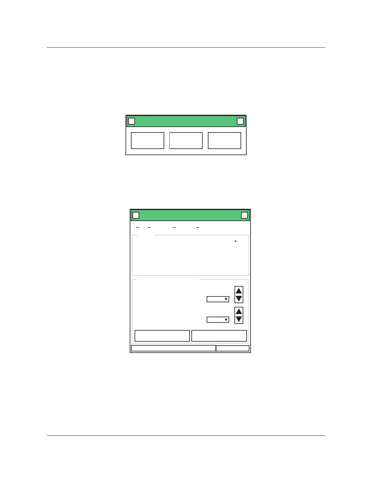
1-44 Equipment operation Nortel Networks Confidential
411-2051-500 Draft 00.01 November 1999
3. Turn on the power to the computer and the MCPA shelf.
4. Start the ‘Nortel gain’ program from the Start menu on the computer. The
selection menu for the MCPA will pop out (see Figure 1-10). Select the
100W MCPA system.
Figure 1-10
Selection menu for the MCPA
5. The power setting menu for the MCPA will pop out (see Figure 1-11).
Figure 1-11
Power setting menu for the MCPA
6. Click on the Comm Port parameter on the menu. Set the Comm Port
(COMM1, 2, 3, or 4) parameter to match the physically-connected serial
communications port on the computer.
Note: To verify communications between the computer and the MCPA
shelf, check for a temperature reading on the menu. If there is no
temperature reading, the Comm Port parameter may not match the
Powerwave/Nortel Model NTFC07BB X
50W MCPA
System 100W MCPA
System Exit
Universal Enclosure System X
File CommPort Download About
Temperature 35.652 C
Current output power 59.89 Watts
Maximum available 100 Watts
output power
Watts
Target output power per channel 2.5
Channels
Number of channels 24
Firmware Version 2.1 10:22 AM
Start Initalization Shipping parameter
Program Gain Initalization
Status

Nortel Networks Confidential Multi-Channel Power Amplifier (MCPA) 1-45
Wireless Solutions DualMode 800 Enclosure Maintenance Manual MTX08
communications port on the computer. Select the right port on the menu.
You can also check for communications by turning on or off the power of
an MCPA module using the RF ON switch on the front panel of the
module. The maximum available power reading on the menu should
change according to the number of powered-on MCPA modules (120W
for three modules, 80W for two modules, and 40W for one module).
If necessary, restart the software program to re-establish communications.
Fixing the ‘Run-time error’ problem
The reason you will get a ‘Run-time error’ is when choosing a comm port that
is not available. Verify that no other program is open and using the comm port
that the MCPA software is trying to use. If a ‘Run-time error’ message appears
every time you try to run the software, use the following procedure to fix the
problem:
1. Use the Windows Explorer to view the Windows directory.
2. Double-click on the ‘REGEDIT.EXE’ file. A Registry Editor will open.
3. Double-click on the directory ‘HKEY_CURRENT_USER’.
4. Double-click on the directory ‘SOFTWARE’.
5. Double-click on the directory ‘VB and VBA Program Settings’.
6. Double-click on the directory ‘Powerwave RD Testing’.
7. Double-click on the directory ‘System’.
8. Double-click on the ‘CommAlarmBoard’ file in the file panel.
9. A dialog box will open and a ‘1’ should be typed in the ‘value data’ entry
box. This refers to Comm Port 1. If a ‘1’ is already in the entry box, you
might want to try 2, 3 or 4.
10. Choose ‘OK’. The number ’1’ or the number you entered should be
displayed on the data column next to the CommAlarmBoard.
11. Close the Registry Editor.
12. Run the MCPA software again.
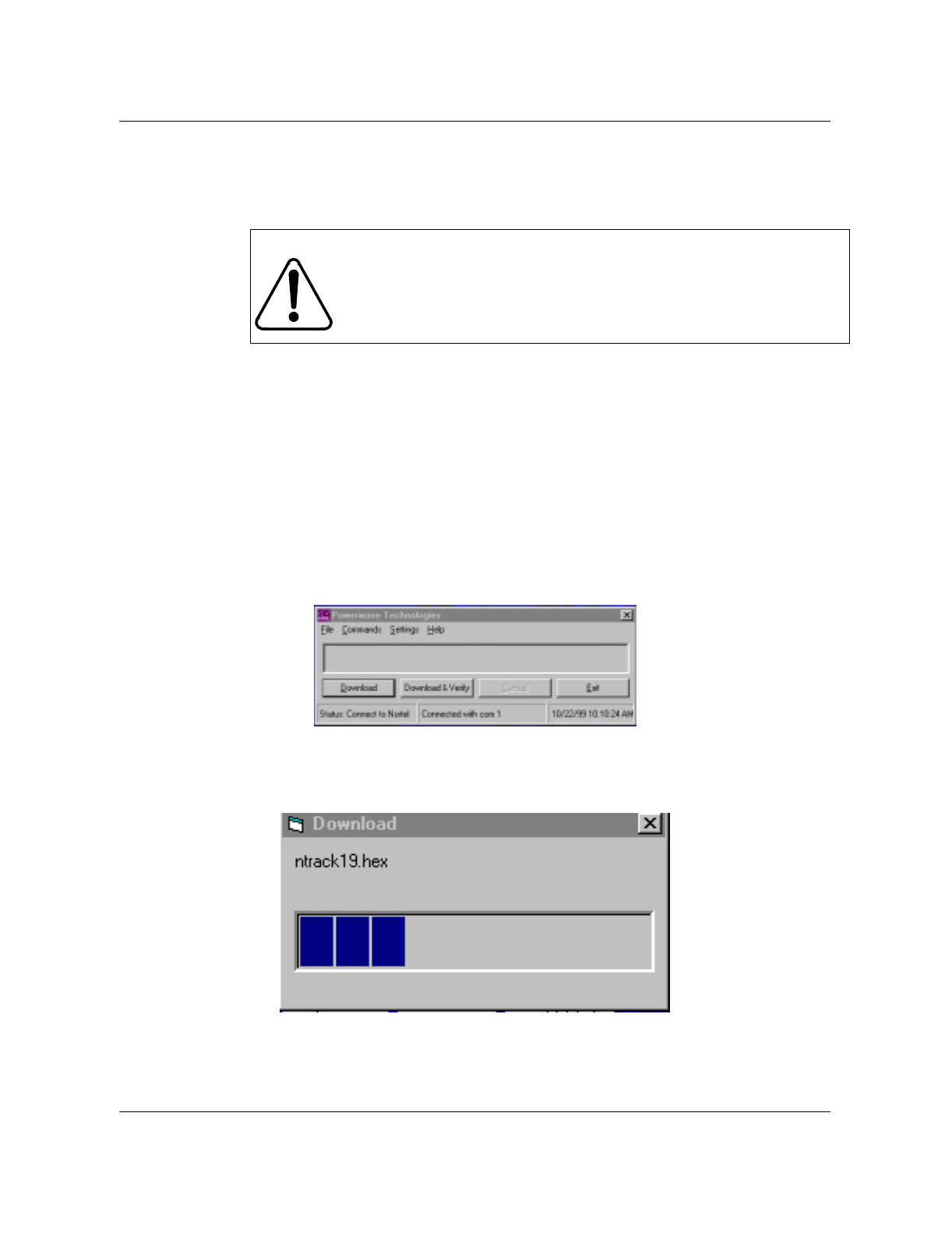
1-46 Equipment operation Nortel Networks Confidential
411-2051-500 Draft 00.01 November 1999
Downloading the MCPA firmware to the MCPA shelf (if required)
Note: This procedure is required only if you need to upgrade the MCPA
firmware from version 2.1 to a newer version.
Use the following procedure if you need to download the firmware to the MCPA
shelf:
1. Run the ‘Nortel gain’ program by performing Steps 1 to 5 of the
procedure listed in the Running the MCPA software on the computer
section. The power setting menu will pop out (see Figure 1-11).
2. At the menu, click on the Download parameter and then select the
software version, for example, NTRACK2_2.HEX.
3. At the ‘Powerwave Technologies’ menu, select ‘Download’.
4. At the ‘Warning’ menu, select ‘OK’. The screen will show the following:
5. Midway through the download process, the secreen will turn to the
following:
6. When download is complete, the software will display ‘Download is
complete’ on the screen. Click ‘OK’. The shelf is ready for operation.
IMPORTANT
Power to the MCPA shelf must remain on during the
downloading period.
Nortel Networks Confidential Multi-Channel Power Amplifier (MCPA) 1-47
Wireless Solutions DualMode 800 Enclosure Maintenance Manual MTX08
Setting the MCPA output power
After installing the software on the computer or downloading the firmware to
the MCPA shelf, you can begin to set the output power for the MCPA shelf.
The MCPA output power setting determines the per carrier power as well as
the maximum power to be transmitted by the MCPA modules. Here are some
examples of how to calculate and set the MCPA output power.
• If your cell/sector has 16 channels and you want to transmit an output
power of 2.5 watts per channel, enter:
2.5 in the “Target output power per channel” box, and
16 in the “Number of channels” box
This sets the per channel output power to 2.5 watts and the total MCPA
output power of the 16 channels is 40 watts (16 channels x 2.5 watts).
• If the capacity of the cell/sector is reduced to 12 channels, the per channel
output power remains at 2.5 watts while the total MCPA output power is
reduced to 30 watts (12 channels x 2.5 watts).
In this case, you do not need to set the power level again if the per channel
output power is at the desired level. However, if you need a new per
channel power level, you have to set the output power level again.
• If the capacity of the cell/sector is increased to 24 channels, the per
channel output power decreases to 1.67 watts while the total MCPA
output power remains at 40 watts (24 channels x 1.67 watts).
In this case, if you want to maintain the per channel output power at 2.5
watts, you need to enter the requirements again. So, enter:
2.5 in the “Target output power per channel” box, and
24 in the “Number of channels” box
This sets the per channel output power to 2.5 watts and the total MCPA
output power of the 24 channels is 60 watts (24 channels x 2.5 watts).
Note: You must use two MCPA modules to obtain a total output power of
higher than 100 watts.
IMPORTANT
The calculation refers to output at the MCPA shelf. If you need
the output power at the antenna port of the duplexer, you must
add the insertion loss into your calculation.
1-48 Equipment operation Nortel Networks Confidential
411-2051-500 Draft 00.01 November 1999
Power setup procedure
To set the MCPA output power, use the following procedure:
1. Run the ‘Nortel gain’ program by performing Steps 1 to 5 of the
procedure listed in the Running the MCPA software on the computer
section. The power setting menu will pop out (see Figure 1-11).
2. Enter the target output power and the number of channels supported by
the MCPA shelf in their respective areas on the menu.
3. Initialize the setting by clicking the Start Initialization menu bar. If the
Start Initialization bar is not active (grayed out) on the menu, re-entering
the output power level will bring it on (active) again.
4. A prompt requiring that all carriers are on will appear. Make sure that the
number of turned-on carriers (TRUs) matches the number of channels
entered. Click ‘OK’.
5. At the ‘Initialization Done’ prompt, click ‘OK’. Power set up is
complete.
IMPORTANT
Nortel Networks recommends that ALL channels (with at least
eight channels) be turned on at the time of initial power
setting. Otherwise, accuracy of the output power may be
affected.
IMPORTANT
Suppose that your cell/sector is using 16 channels at the time
of the power set up and you plan to expand it to 24 channels in
the future. You can enter 24 as your number of channels for the
cell/sector. However, for output accuracy, you should have all
24 channels turned on at the time of initialization. If you do not
have the eight expansion channels ready, it is best to keep the
number of channels to 16 at this time and perform
initialization again at the time when the cell/sector expands to
24 channels.

2-1
Wireless Solutions DualMode 800 Enclosure Maintenance Manual MTX08
Periodic maintenance 2
This section briefly discusses all aspects of cell site maintenance, and when
necessary, refers you to detailed testing procedures in other operational tests
in this manual.
Periodic maintenance records
Periodic maintenance helps you in two ways:
• it allows you to detect and replace degraded equipment before it affects
service
• it allows you to take steps to protect equipment from damage or
degradation
To support these functions, you must keep records. Records allow you to:
• recognize deteriorating performance by comparing current and past test
results
• ensure that all steps required to protect equipment have been taken
• create a maintenance history of a cell site; thereby allowing you to plan
for the future and predict future maintenance needs
• provide information to decide sparing levels and ‘out of expectation’
failure level for specific equipment
For maximum benefit, maintenance records should be kept on site and should
be well organized so that call-out staff have access to and can determine the
maintenance history of a particular site. Referenced documents such as this
manual will contain blank forms for recording specific test results. These
forms should be copied as required and included with your records.
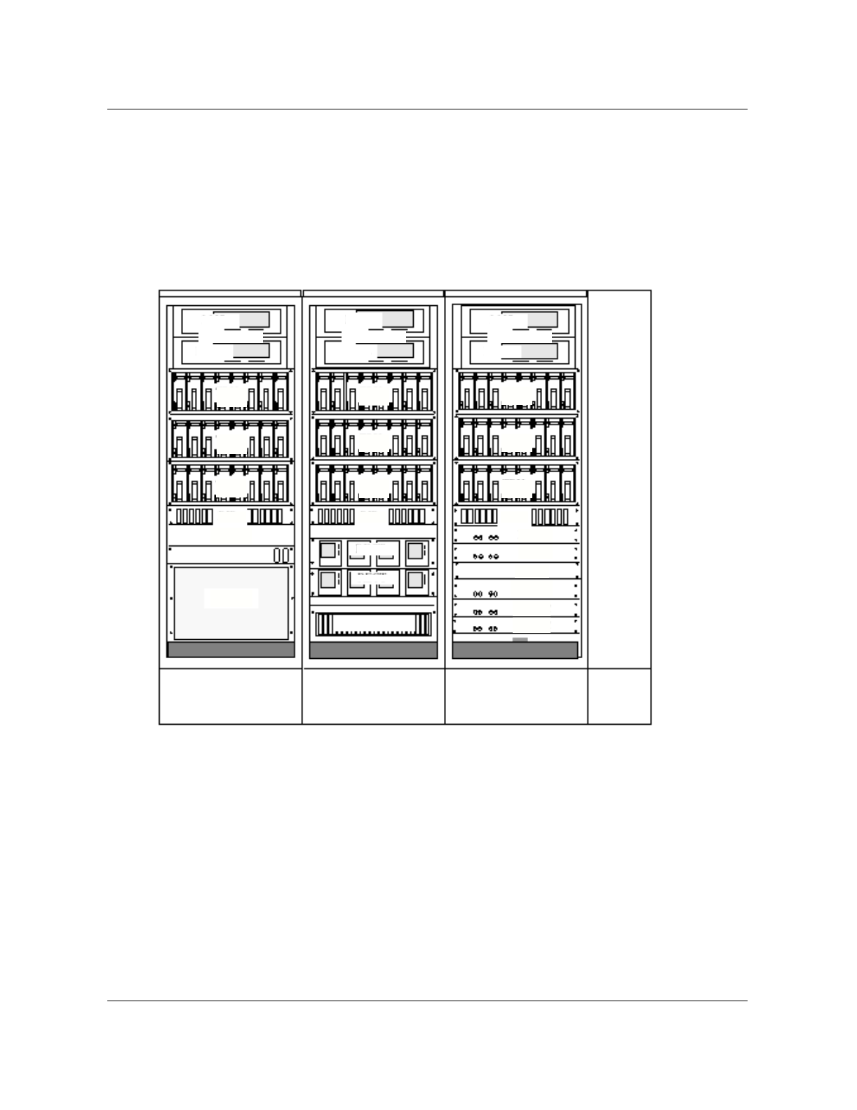
2-2 Periodic maintenance
411-2051-500 Draft 00.01 November 1999
Equipment in a DualMode 800 Enclosure
Figure 2-1 shows the location of equipment in a DualMode 800 Enclosure.
Figure 2-1
Equipment layout of a DualMode 800 Enclosure
Bay 1 Bay 2 Bay 3
Interface
Module
ICRM
RIP1 RIP2 RIP3
DCSM
ACU
HSMO
ERMC1
ERMC2
ERMC3
CSU
DCLC
Battery Pedestal
Rectifiers
Rectifiers
PCS
125
33
41
26 31 32 49 50 55 56
40 57
65
64
72
48
9
17
278
16
24
4
5
1
8
TRU
Shelf1
TRU
Shelf2
TRU
Shelf3
TRU
Shelf4
TRU
Shelf5
TRU
Shelf6
TRU
Shelf7
TRU
Shelf8
TRU
Shelf9
MCPA1
MCPA2
MCPA3
MCPA4
MCPA5
MCPA6
MCPA Shelf1 MCPA Shelf2 MCPA Shelf3
Legends:
ACU Alarm Control Unit HSMO High Stability Master Oscillator
CSU Channel Service Unit MCPA Multi-Channel Power Amplifier
DCLC DC Load Center PCS Power Control Shelf
DCSM DualMode Cell Site Monitor RIP Rack Interface Panel
ERMC Enhanced Receive MultiCoupler TRU Transmit Receive Unit
ICRM Integrated Cellular Remote Module

Transmission facilities 2-3
Wireless Solutions DualMode 800 Enclosure Maintenance Manual MTX08
Transmit Receive Unit (TRU) and Multi-Channel Power Amplifier (MCPA)
The Transmit Receive Unit (TRU) needs no periodic testing in either the
analog or the digital mode — only do testing if you suspect a fault or want to
verify correct operation. The bit error rate (BER) test is typically used for
troubleshooting. BER is defined as the ratio of erroneous bits to the total
number of received bits in a transmission system. Another troubleshooting
test is the TDMA Modulation Accuracy Test which measures the Error Vector
Magnitude(EVM). The Multi-Channel Power Amplifier (MCPA) should be
tested for power output once a year. For these tests, refer to Chapter 11,
DualMode Radio Unit Testing, in this manual.
High Stability Master Oscillator (HSMO)
In dual-mode (mixed analog and digital) or digital sites, the HSMO frequency
should be checked once a year. In analog cell sites, the frequency is not as
critical and the HSMO need not be tested at all. Any problems with the
HSMO in an all analog cell site will show up in the TRU transmit frequency
tests. Refer to the tests in Chapter 5, HSMO Tests, in this manual.
Alarm Control Unit (ACU)
The ACU alarm input points for equipment such as fans, over-temperature
and door switches should be verified once a year. Alarm output contacts and
alarm reactions should be verified at the same time. Refer to the tests in
Chapter 8, ACU Tests, in this manual.
Transmit path insertion loss
Check the insertion loss of the transmit path once a year or as required by
base station carrier power level test results.
Fuses/breakers/fans
The ACU monitors the status of the fuses, breakers and fans. It is good
practice whenever you are at the cell site to visually inspect the fuses, check
that the correct breakers are on and that the fans are working.
Other equipment
Equipment not already specifically mentioned does not require periodic
maintenance.
Transmission facilities
Transmission facilities include pressurized transmission lines, microwave
radio equipment and any copper facilities. It is important that your facilities
are in good condition, otherwise cell site performance might be
compromised. See recommended maintenance intervals from the
manufacturer for the specific equipment.

2-4 Periodic maintenance
411-2051-500 Draft 00.01 November 1999
Microwave
Refer to the manufacturer’s instructions for periodic maintenance.
Transmission level and noise tests should be conducted once a year.
Copper audio link
The susceptibility of copper to noise and level problems requires more
frequent checks than digital or microwave facilities. Perform noise and level
checks quarterly on the T-1 transmission facilities.
Power
Clean, reliable power is essential to your cell site. The following are generic
periodic maintenance recommendations. Consult the manufacturer's
documentation for specific maintenance and specifications.
BatteryThe batteries used in the DualMode 800 Enclosure are virtually maintenance
free. For routine check or maintenance procedures, refer to manufacturer's
recommendation.
Rectifiers
The rectifiers used in the DualMode 800 Enclosure are virtually maintenance
free. For information, refer to the DualMode 800 Enclosure Functional
Description, 411-2051-100.
Fuses/breakers
Whenever you arrive an enclosure site, it is a good idea to verify that the
circuit breakers are on and the fuses are good.
Cabling and connections
Whenever equipment is installed or changed, check the cabling and
connections. Take note of any suspect cables that give you problems from
time to time.
Inside grounding
Inside grounding performs two functions: it prevents noise from one unit
getting into other equipment, and it ties all equipment together for protection.
In addition to checking for and repairing any deterioration of the grounding
system, you should also check to see that all new equipment installed at the
site is grounded properly. (Refer to the DualMode 800 Enclosure Power and
Ground Verification.)

Outside grounding 2-5
Wireless Solutions DualMode 800 Enclosure Maintenance Manual MTX08
Bay bonding
Individual bays in a line-up should be bonded together with 3/8 inch or larger
bolts with star washers bearing on plated metal or conductive tape.
Cabling and connections
Each frame line-up should be grounded to the principle ground bar with #2
AWG insulated wire. There should be individual drops from this cable to each
frame. The frame grounds should not be connected to the DC return bar at the
top of the frames nor should they be attached to the halo ground when used.
Principle ground bar
All inside ground connections should lead back to the principle ground bar,
which is then connected to the outside ground field and the AC ground. Check
all connections and ensure that new or changed equipment is properly
grounded. If there is a water pipe at the site, the principle ground bar should
be connected to it.
Transmission line entrance
The transmission line to the antenna should be lightening-protected where it
comes into the enclosure. Check the condition of the grounding connections
once a year and also following any severe lightening storm activity.
Outside grounding
A typical cell site, with its tall metal structures and antennas, is an open
invitation to a lightening strike. To avoid cell site degradation or total loss due
to electrical storm activity, you should inspect your grounding system just
before the local thunderstorm season. Checking the outside ground can be
part of a site walk-around check, where you also check antennas, cables,
structures, lighting and foundations.
Tower and associated structures
Use a pair of binoculars or a spotting scope to verify that the air terminal
(lightning rod) and antennas are still attached to the tower and grounding
system. Verify that:
• the antenna feed cables are grounded at both ends
• the cables and clamps attaching the tower and waveguide bridge to the
grounding system are secure
• the cables and clamps connecting the guy wires to the grounding system
are secure
• transmission cables are grounded at both the top and the bottom of the
tower, and at the enclosure entrance

2-6 Periodic maintenance
411-2051-500 Draft 00.01 November 1999
Building sheath, fences and other equipment
If the site has metal walls, roof or base, the metal components must be
grounded. The cell site fence and any fuel tanks or other metal structures must
be grounded as well. Check that grounding cables and clamps are secure.
Antennas and tower
Structure
Detailed inspection of towers should be performed every one to three years by
an experienced inspector who can climb the tower and check all components.
Cell site maintenance personnel can perform an effective partial inspection
without leaving the ground, and this is recommended:
• once a year
• following a severe storm
• following a prolonged period of heavy icing
Use binoculars or a spotting scope if necessary. To perform a partial inspection:
• check the tower base for cracks, concrete break up and upheaval
• check all guy anchors for cracks or upheaval
• check guy tension and attachment
• check fasteners for security
• check all components for rust
• check for flaking paint (often a sign of over-stress)
Tower lighting
Visually confirm operation of the tower lights every time you are at the site
after dark. When the tower is climbed for structural inspection, the lights
should be thoroughly checked at the same time.
Grounding
Check all grounding that is accessible from the surface during your outside
grounding check. When the tower is climbed for structural inspection,
grounding on the higher parts of the tower should be checked at the same
time.
Paint Painted towers need to be re-painted every few years. Check the over-all
condition of the paint on an annual basis and re-paint as necessary.

Site performance 2-7
Wireless Solutions DualMode 800 Enclosure Maintenance Manual MTX08
Feed Check that the transmission line is adequately supported and protected
between the enclosure and the antenna tower.
Antennas
When the tower is climbed for structural inspection, antennas should be
inspected as well. Check for:
• correct orientation and tilt
• crack, dents and burns
• fasteners, attachment and security
• transmission line and ground attachment security
• audible gas leakage in pressurized systems
Pressurized transmission lines
If a pressurized transmission line to the antenna is used, check the nitrogen
tank pressure and manifold pressure every visit. Check the dehydrator at the
same time.
Site performance
The ultimate measure of the cell site’s condition is the cell site’s actual
measured performance. Site performance should be tested once a year and
can be gauged by the following tests. It should be taken into consideration
that coverage and handoffs can be impacted by seasons and weather.
Fringe coverage
Using the most recent coverage maps, take a test mobile and drive to the
fringe of the site coverage area with a call established to confirm coverage.
Most mobiles are able to access signal strength function mode.
Handoff checks
Using the standard drive defined for the site or system acceptance procedures,
with a call established drive across the cell boundaries. Confirm that the
handoffs occur in the appropriate places and that there is sufficient hysteresis
to prevent ping-ponging of calls. You can use a test mobile with channel-
indicating firmware to check the exact location of the handoffs.
Antenna sweep
Measure the reflected power from the antenna across the entire cellular band
(receive and transmit) to check for hidden damage or deterioration of the
antennas. Refer to Chapter 7, Antenna Tests, in this manual.

2-8 Periodic maintenance
411-2051-500 Draft 00.01 November 1999
Housekeeping
Heating/air conditioning
Proper temperature is essential to the functioning of the enclosure. Check any
alarms due to the environment, such as high or low temperature, every time
you are at the site.
Dust control
Keep dust levels to a minimum by mopping the floor once a month, taking
care not to get the equipment wet. Whenever you remove a transceiver or
power amplifier, wipe off the dust on the unit and shelf slides. Dust
accumulation on circuit boards and heat sinks interferes with heat dissipation
and shortens the life of the equipment. Dust in the air clogs fans and air
conditioners, also raising the temperature.
Statutory requirements
Fire equipment, hazard signs and exit signs may be required by law. Make
sure required signs are present and safety equipment is maintained.
Site licenses
Radio and tower and business licenses are often required to operate a cell site.
It may be worth your while to check up on these once a year to ensure that
they are being maintained, whether they are located on the site or with your
company’s legal department.
Trash and loose articles
Keep the inside of your enclosure as clean and tidy as possible. Trash and
loose articles pose fire and tripping hazards and should be removed after
every visit.
Site grounds keeping
Tall grass can present a fire hazard; poorly kept trees can lean on or fall on the
enclosure. Snow and ice removal on and around the enclosure may be a
statutory or legal liability requirement in some jurisdictions. Grounds keeping
is often contracted out to a specialty firm.
Building service
If the enclosure uses AC mains service from overhead poles, take a look at the
drop and service entrance once a year. Look for obviously damaged insulation
and threats from overhanging trees.
Security
Check fences, gates, barbed wire and razor ribbon, both around the site and
around the tower guy anchors. Check door locks and gate locks before leaving
the site.

Schedule for periodic cell site maintenance 2-9
Wireless Solutions DualMode 800 Enclosure Maintenance Manual MTX08
Manuals and records
Manuals and site logs should be organized and readily accessible to call-out
staff. All records should be completed before leaving the site. All logs and
records should be kept on-site for instant availability.
Schedule for periodic cell site maintenance
Regularly scheduled visits are important for the preventative maintenance of a
cell site. However, if maintenance teams are responsible for a number of cell
sites, maintenance schedules for the different sites should be staggered so that
labour time is more effectively and efficiently managed. Table 2-1 shows an
example of a maintenance schedule for six cell sites where the periodic
routines are distributed evenly throughout a one year period.
A cell site maintenance reference chart and preventive maintenance check
lists are provided in the following pages.
Table 2-1
Maintenance schedule example
Cell Jan Feb Mar Apr May Jun Jul Aug Sept Oct Nov Dec
#1 1 yr mo mo qtr mo mo 6 mo mo mo qtr mo mo
#2 mo mo 1 yr mo mo qtr mo mo 6 mo mo mo qtr
#3 mo qtr mo mo 1 yr mo mo qtr mo mo 6 mo mo
#4 6 mo mo mo qtr mo mo 1 yr mo mo qtr mo mo
#5 mo mo 6 mo mo mo qtr mo mo 1 yr mo mo qtr
#6 mo qtr mo mo 6 mo mo mo qtr mo mo 1 yr mo

2-10 Periodic maintenance
411-2051-500 Draft 00.01 November 1999
DualMode 800 Enclosure Maintenance Reference Chart
Every
Visit Monthly Quarterly Semi-
Annual Annual Comments
Equipment Bays and Interface Module
Fans/Breakers/Fuses •
HSMO Tests
Oscillator Power Level (Ch. 5) •
Oscillator Frequency (Ch. 5) •
TRU Receive Tests - Analog
Receive Sensitivity (Ch. 11) •
Receive Audio Level (Ch. 11) •
RSSI Curve (Ch. 11) •
SAT Detect (Ch.11) •
ST Detect (Ch.11) •
Audio Loopback (Ch.11) •
TRU Transmit Tests - Analog
PA Carrier Power Level (Ch.11) •
Transceiver Carrier Level Test (Ch.11) •
Transmit Carrier Frequency (Ch.11) •
Modulation Limiting (Ch.11) •
Transmit Audio Deviation (Ch.11) •
Residual Modulation (Ch.11) •
Wideband Modulation (Ch.11) •
SAT Frequency Deviation (Ch.11) •
TRU Audio Alignment Tests - Analog
Voice Forward Line Level (Ch.11) •
Voice Reverse Line Level (Ch.11) •
PA Power Output (Ch.11) •
- continued -

DualMode 800 Enclosure Maintenance Reference Chart 2-11
Wireless Solutions DualMode 800 Enclosure Maintenance Manual MTX08
TRU Digital Tests - TDMA
TDMA Modulation Accuracy (Ch.11) Troubleshooting
Bit Error Rate (BER) (Ch.11) Troubleshooting
ACU Tests
Alarm Control Unit (Ch.8) •
Transmit Path Tests
Insertion Loss (Ch.11) •
RMC Tests
Insertion Loss (Ch.7) Troubleshooting
Transmission Facilities
Copper Audio Link (voice, T1) •
Power
Fuses, Breakers •
Battery & Rectifiers •
Voltage and polarity on the bays • +
Commissioning
Inside Grounding
Bay Bonding •
Cabling and Connections •
Principle Ground Bar •
Transmission Line Entrance •
Outside Grounding
Tower and Associated Structures •
Building Sheath, Fences and other
Equipment •
- continued -
Every
Visit Monthly Quarterly Semi-
Annual Annual Comments

2-12 Periodic maintenance
411-2051-500 Draft 00.01 November 1999
Antennas and Tower
Structure •
Tower Lighting •
Grounding •
Paint •
Feed •
Antennas •
Pressurized Transmission Lines •
Site Performance
Fringe Coverage •
Handoff Checks •
Antenna Sweep •
Housekeeping
Heating/Air Conditioning •
Dust Control •
Statutory Requirements •
Site Licenses •
Trash and Loose Articles •
Site Grounds Keeping •
Building Service •
Security •
Manuals and Records •
- End -
Every
Visit Monthly Quarterly Semi-
Annual Annual Comments

DualMode 800 Enclosure Every Visit Checklist 2-13
Wireless Solutions DualMode 800 Enclosure Maintenance Manual MTX08
DualMode 800 Enclosure Every Visit Checklist
Date:____________________________ Performed by:___________________________
Equipmene bays
1 Check all breakers for correct position, that is, ON/OFF on all power equipment
2 Check fuse indicators; replace fuses if necessary
3 Check receive multicoupler fuse
4 Verify that all cooling fans are working in each bay
Enclosure and site
5 Check that no high or low temperature alarm is present
6 Check that the interior lights work
7 Verify automated security system by tripping alarm (reset after test)
8 Check air filters on air exchange/conditioner equipment
9 Verify the presence of a fire extinguisher & check expiry date
10 Check for leaks in the shields
11 Check the condition around the enclosure
12 Check for deterioration of paint on walls
13 Check cable access ways through the walls for deterioration
14 Inspect grounding system
15 Perform general housekeeping duties to remove dust, dirt and trash
16 Complete manuals, site logs, and records
17 Turn tower lights on and verify that all lights are working
18 Inspect antenna ground for corrosion
19 Security checks on fences, windows, doors, tower guy anchors
20 Check that site gate locks are secure
21 Clean up any debris around the site area
22 Check that there are no overhead lines down
Pressurized transmission lines to antenna
23 Check the nitrogen tank pressure, manifold, and the dehydrator

2-14 Periodic maintenance
411-2051-500 Draft 00.01 November 1999
DualMode 800 Enclosure MONTHLY Checklist
Date:____________________________ Performed by:___________________________
1 Perform the EVERY VISIT routine checks
Power - Battery
2 Check the battery voltages and note any discrepancies.
3 Check terminals, connectors for signs of moisture or corrosion
Power - BCM
4 Check that the BCM output voltage is within specification
Housekeeping
5 Mop the floors at least once a month to keep dust levels to a minimum

DualMode 800 Enclosure QUARTERLY Checklist 2-15
Wireless Solutions DualMode 800 Enclosure Maintenance Manual MTX08
DualMode 800 Enclosure QUARTERLY Checklist
Date:____________________________ Performed by:___________________________
1 Perform the EVERY VISIT routine checks
2 Perform the MONTHLY routine checks
Equipment bay
3 Voltage and Polarity checks at Main Power Terminals
Step 6 of Voltage Checks Test (See Chapter 4)
Transmission facilities
4 Perform noise and level checks on T-1 transmission facilities (optional)

2-16 Periodic maintenance
411-2051-500 Draft 00.01 November 1999
DualMode 800 Enclosure SEMI-ANNUAL Checklist
Date:____________________________ Performed by:___________________________
1 Perform the EVERY VISIT routine checks
2 Perform the MONTHLY routine checks
3 Perform QUARTERLY routine checks

DualMode 800 Enclosure ANNUAL Checklist 2-17
Wireless Solutions DualMode 800 Enclosure Maintenance Manual MTX08
DualMode 800 Enclosure ANNUAL Checklist
Date:____________________________ Performed by:___________________________
1 Perform the EVERY VISIT routine checks
2 Perform the MONTHLY routine checks
3 Perform QUARTERLY routine checks
4 Perform SEMI-ANNUAL routine checks
Equipment bays
5 Test TRU and MCPA for power output
TRU Output Power Test
6 Test the ACU alarm input points
Alarm Control Unit Tests
7 Check the Insertion Loss of the Transmit Path
Insertion Loss
8 Check HSMO Frequency on mixed or all dual mode sites
Oscillator Frequency Test
Power - Rectifiers
9 Test the alarm/cut out sections on the rectifiers by adjusting the high and low voltage
Inside grounding
10 Check that each bay line-up is grounded to the principle ground bar with #2 AWG
insulated wire and individual drops from this cable to each bay
11 Verify all inside ground connections lead back to the principle ground bar.
12 Check all connections, ensure new or changed equipment is properly grounded
13 Check that the transmission line to the antennas is lightning protected where it comes
into the building.
14 Check the condition of the grounding connections for corrosion
Outside grounding
15 Using binoculars or a spotting scope, verify that the air lightning rod and antennas are
still attached to the tower and grounding system
16 Verify that the antenna feed cables are grounded at both ends
17 Verify that the cables and clamps attaching the tower and waveguide bridge to the
grounding system are secure
- continued -

2-18 Periodic maintenance
411-2051-500 Draft 00.01 November 1999
18 Verify that the cables and clamps connecting the guy wires to the grounding system are
secure
19 Verify that transmission cables are grounded at both the top and bottom of the tower,
and the building entrance
20 Buildings with metal walls, roof or base, all metal parts are grounded
21 Site fence, fuel tank or other metal structures are grounded
22 Check that grounding cables and clamps are secure
Antennas and tower
23 Check the tower base for cracks, concrete break up and upheaval
24 Check all guy anchors for cracks or upheaval
25 Check guy tension and attachment
26 Check fasteners for security
27 Check all components for rust
28 Check for flaking paint (often a sign of over-stress)
29 Check the over-all condition of the paint; re-paint if necessary
30 Check that the transmission line is adequately supported and protected between the cell
site building and the antenna tower
31 When tower is climbed, check grounding on the higher parts
32 When tower is climbed, check the tower lights
33 When tower is climbed, perform structural inspection of antenna:
• Check for correct orientation and tilt
• Check for cracks, dents, burns
• Check for fasteners, attachment and security
• Check for transmission line and ground attachment security
• Check for audible gas leakage in pressurized system
Site performance
34 Confirm coverage by making calls from the fringe of the site coverage area
35 Confirm handoffs by driving across the cell boundaries with a call established
36 Perform an antenna sweep test
- continued -

DualMode 800 Enclosure ANNUAL Checklist 2-19
Wireless Solutions DualMode 800 Enclosure Maintenance Manual MTX08
Housekeeping - Environment
37 Check for insects, mouse and birds nest in intake and exhaust systems
38 Inspect temperature in all equipment bays
Licenses and other requirements
39 If the building uses AC mains service from overhead poles, take a look at the drop and
service entrance for obvious damaged insulation
40 Ensure the necessary licenses are maintained
- End -

2-20 Periodic maintenance
411-2051-500 Draft 00.01 November 1999

3-1
Wireless Solutions DualMode 800 Enclosure Maintenance Manual MTX08
Test equipment and precautions 3
The DualMode 800 Enclosure is basically operated by the Digital Multiplex
Switch - Mobile Telephone Exchange (DMS-MTX*). It can also be operated
by a service personnel at the cell site through an interface terminal to perform
some operational functions and tests. This manual provides information on
how to operate the cell site equipment and perform maintenance tasks and
operational tests at the cell site. However, some of the tests may involve
activities at the MTX switch. For details of the MTX activities, refer to the
appropriate DMS-MTX manuals.
To operate and test cell site equipment, an interface terminal and some other
test equipment are required. This chapter provides a list of recommended test
equipment and precautions to be aware of when performing any tasks at the
cell site.
Test equipment
It is assumed that the operator is familiar with the test equipment used in the
test procedures. The following test equipment is recommended for
performing the required tests. Any functionally equivalent unit may be used
in its place. Double shielded coaxial cables are recommended for use between
test equipment and the equipment being tested.
Note: Ensure test equipment is calibrated before performing any tests.
1. Communications Monitor (examples as listed below):
— IFR 1600, 1900
— Marconi 2955A e/w C-Message Filter option #54499-043S and
OCXO option #52955-900A
— Motorola 2600
— Hewlett Packard 8921, 8935
2. Interface Terminal: VT100 Video Display Terminal or equivalent (lap-top
PC with communications software) e/w null modem cable
— Set up the parameters of the terminal as follows:

3-2 Test equipment and precautions
411-2051-500 Draft 00.01 November 1999
– 9600 baud
– 8 data bits
– 1 stop bit
– No parity
– 80 columns
– Auto wraparound
–ANSI
– VT100 emulation
— Cable for connecting the Transmit Receive Unit (RJ45 Teledapt
connector on the front panel of the TRU) to the Interface Terminal.
Table 1-1 shows the pin-outs for different types of terminal
connectors.
3. HP 3551A Transmission Test Set
4. Spectrum Analyzer 0 to 2 GHz, 70 dB dynamic range
5. Two 1.5 meter N-male to N-male RF Cables
6. Two 1.5 meter N-male to BNC-male RF Cables
7. Two 1.5 meter BNC-male to BNC-male RF cables
8. Narda 370BNN 50 ohm Terminations
9. Bird 8325 Coaxial Attenuator, 500 Watts, 30 dB,
10. Bird Thruline Wattmeter e/w 5, 50 and 250 Watt Elements
11. HP336 power meter
HP436A power meter
12. Bird 4275 Adjustable Radio Frequency Sampler
13. Fluke 8050A Digital Multimeter
Table 3-1
DRU to Interface Terminal connection
DRU Interface Terminal Function
TRU front panel
RS-232 port
pin number
25 pin
D-connector
pin number
9 pin
D-connector
pin number
8 pin Macintosh
connector
pin number
2 3 2 3 TX from DRU
3 2 3 5 RX to DRU
7754Ground
Precautions 3-3
Wireless Solutions DualMode 800 Enclosure Maintenance Manual MTX08
14. Directional Compass
15. Binoculars or Spotting Telescope
16. Frequency counter: 1 Hz resolution and 0.025 ppm reference
Note: Frequency counter should be a factor of 10 more stable than the
oscillator being measured, for example, Hewlett Packard 53181A with
option 12 Frequency Counter.
17. PC or laptop with the MCPA software package and a null modem cable
(see the MCPA section in Chapter 1, Equipment operation, for details)
Precautions
Equipment warm-up
Do not perform tests immediately after the installation of any equipment. The
TRU, the MCPA, the ICRM and the test equipment should be powered up for
at least half an hour before the tests. Inaccurate measurements may result if
the warm-up period is less than 30 minutes.
Test equipment
Proper setup of the test equipment is critical in obtaining proper test results.
Consistency of setup and techniques from one person to another is essential
for obtaining proper system operation. Calibrate all test equipment before
use.
Rule of thumb—subtracting 3 dB halves the power level:
• +45.0 dBm is approximately 32 watts
• +33.0 dBm is approximately 2 watts
• +30.0 dBm is approximately 1 watt
• +27.0 dBm is approximately 1/2 watt
• 0 dBm is approximately 0.001 watt (1 milliwatt)
CAUTION
Equipment damage
Make sure that the test equipment maximum allowable input
levels are not exceeded. Add an attenuator to reduce the power
if necessary.
3-4 Test equipment and precautions
411-2051-500 Draft 00.01 November 1999
RF radiation hazard
Radio Frequency (RF) radiation is hazardous to anyone working in the cell site.
All RF cables should be connected properly and all unused RF ports should be
terminated with an appropriate terminator.
Electrostatic Discharge (ESD) control
This section provides general guidelines and precautions for handling,
transporting and storing components and printed circuit wiring boards that are
susceptible to permanent damage when subjected to electrostatic discharge
(ESD).
ESD sensitive equipment
Various electrical and electronic components are vulnerable to electrostatic
discharge (ESD). These include:
• discrete components
• hybrid devices
• Integrated Circuits (ICs)
• boards assembled with these devices
Identification
Manufacturers vary in their methods of identifying static-sensitive equipment.
They may apply stickers or mark components with various colors, but many do
not indicate that their products are sensitive. Examples of identification are:
• circuit boards with ESD-sensitive devices have a red edge
• hybrids containing Metal-Oxide Semiconductors (MOS) devices are red,
with the letters MOS on the back. Non-sensitive hybrids are white.
• pull-handles on circuit packs containing sensitive devices may have the
letters MOS and the assembly part number printed in red
• assembly drawings may have manufacturing notes describing the circuits
as ESD-sensitive
CAUTION
RF radiation hazard
Do NOT disconnect any RF cables when transmitters are on.
CAUTION
Equipment damage
When in doubt, any circuit board containing microelectronic
components must be assumed to be vulnerable.
Precautions 3-5
Wireless Solutions DualMode 800 Enclosure Maintenance Manual MTX08
Static control materials and devices
Use conductive bags and containers to store and transport circuit boards or
components. There are three common types of conductive bags: Velostat,
Tyvek and Pink Polyethylene.
Note: Pink Polyethylene is not recommended for ESD control.
Static-free work stations
Static-sensitive devices must be removed from packages only at a static-free
work area. The minimum equipment for a static-free work station is:
• conductive bench mat
• operator's conductive wrist strap
Ideally however, locations should be equipped as follows when necessary:
• wrist strap
• shoe grounding straps
• ionized air blower (where required)
• ground cord
• floor mats
•table mats
Where protective measures have not been installed, a suitable alternative
would be the use of a Portable Field Service Grounding Kit (3M part number
8012). This consists of a portable mat and wrist strap. The mat has pockets to
hold circuit boards.
Handling procedures
Degradation may occur at any time during the handling of electrostatic-
discharge-sensitive devices and components. Boards or components should
never come in contact with clothing, because normal grounding cannot
dissipate the static charges on fabrics.
Before handling static-sensitive equipment, personnel must discharge
themselves of any static charge. The most effective method is the use of a
grounded wrist strap combined with correctly installed ground static control
CAUTION
Electric shock hazard
Metalized or carbon bags are conductive and therefore must
not contact live electrical circuits, or they may cause shorting,
sparking, and shock hazards to personnel.
3-6 Test equipment and precautions
411-2051-500 Draft 00.01 November 1999
mats at all work locations. The wrist strap must be permanently attached to
the frame on the basis of one between two frames. Alternatively the straps
may be connected on an as-required basis to the battery return (Ground) jack,
where it is provided.
Handling
Electrostatic-discharge-sensitive devices must be handled only in static-free
locations. These locations must be equipped with grounded table and floor
mats and grounded wrist straps. Also a reasonable relative humidity (RH)
level must be maintained, if economically feasible, of between 20% and 80%
non-condensing. In places where humidification is not practical, the other
static control measures must be carefully observed.
Electrostatic-discharge-sensitive equipment must be handled only after
personnel have grounded themselves via wrist straps, or shoe straps and mats.
No electrostatic-discharge-sensitive device should be removed from its
protective package, except in a static-free location. The recommended
packaging is a form of Faraday cage that will protect the contents against any
charge present under normal conditions. Damaged packaging must be
replaced at once.
All common plastics and other prime generators (for example, nylon carpet,
plastic mats) must be prohibited in the electrostatic-discharge-free area.
Use only static-shielding packing material.
Transporting
A circuit pack must be placed into an anti-static shielding bag before being
removed from the work location and must remain in the bag until it arrives at
a static-free repair/test center.
Where handles or finger holes are provided on circuit packs they must be used
to remove and replace the boards, and care taken to avoid contact with the
connectors and components.
Storage
Improper storage can cause failures in ESD-sensitive components. The
guidelines for environmental factors (temperature, moisture, air pollutants)
are as important during storage as they are for operating. Wider variations of
CAUTION
Equipment damage
At no time must an unprotected circuit board come in contact
with clothing, plastics, or ungrounded personnel.

Precautions 3-7
Wireless Solutions DualMode 800 Enclosure Maintenance Manual MTX08
temperature may be allowable, depending on the type of device. In general,
low temperatures do not damage inactive equipment provided that the device
is slowly raised to normal room temperature before use.
Electrostatic discharge damage to unprotected sensitive devices may occur at
any time. Therefore it is important to keep ESD-sensitive circuit boards and
components in proper protective packages during storage. Discard suspect
bags and use new ones. Whenever possible, units requiring protection should
be identified on the protective packing.
Note: A circuit board in a static shielding bag may be shipped or stored in
a cardboard carton, but the carton must not enter a static-free area such as
a bench top or repair zone.
References
For more information on ESD and its control, refer to the following documents:
• Test Methods for Static Control Products (Huntsman & Yenni, 3M
Company)
• Protection and Handling of ESD-Sensitive Circuit Packs (Bell Canada,
BCP069-8000-501)

3-8 Test equipment and precautions
411-2051-500 Draft 00.01 November 1999

4-1
Wireless Solutions DualMode 800 Enclosure Maintenance Manual MTX08
Power-up procedure 4
Overview
Power-up procedures are used to inspect that the power cabling is correct and
to verify voltage checks.
Complete the power-up procedure before any equipment is plugged into the
equipment shelves.
Perform the procedure whenever a shelf or a unit such as the Alarm Control
Unit (ACU), the DualMode Cell Site Monitor (DCSM), or the High Stability
Master Oscillator (HSMO) is either removed or replaced. If the voltage or
polarity of the DC power is incorrect, equipment damage may result.
DC power inspection
An orderly installation of DC power is required at the enclosure to ensure
ease of expansion as traffic increases.
Step Action Observation
1 Verify that the DC power cables from the
breaker panel on the power bay to the
equipment bays have been run in an orderly
fashion and are secured to the runway.
2 Verify that the lugs have been installed
correctly and, if terminated on aluminum
busbars, have been treated with anti-oxidant.
3 Verify that the minimum bending radius has
not been exceeded on the power cables (see
Table 4-1).

4-2 Power-up procedure
411-2051-500 Draft 00.01 November 1999
Voltage checks
This entire procedure is used for installation and commissioning only.
Figure 5-2 shows the DC breaker assignments on the RIPs. The breakers and
the common ground bar distribute the power/grounding to the individual
shelves through cables that exit out connectors in each side of the RIP. The
cables are then routed down each side of the frame.
4 Verify that the breaker positions on the power
bay have been labeled and are cabled as
indicated on the labels.
Note:
See Tables 5-12 to 5-4 for the RIP
breaker panel assignments.
5 Verify that the equipment bays are bonded to
the principle ground bar line-up feeder with a
#6 AWG jumper.
Table 4-1
Minimum bending radii of power cables
Wire Size Inches Millimeters Wire Sizes Inches Millimeters
14 AWG 11/16 17.5 3/0 AWG 3 3/16 80.5
12 AWG 3/4 19.6 4/0 AWG 3 7/16 87.6
10 AWG 15/16 23.1 300 MCM 4 1/8 104.6
8 AWG 1 3/16 31.0 350 MCM 4 3/8 111.5
6 AWG 1 1/2 39.6 400 MCM 4 5/8 117.3
4 AWG 1 3/4 45.7 500 MCM 5 1/16 128.3
2 AWG 2 1/8 53.3 600 MCM 5 9/16 142.2
1 AWG 2 1/2 63.0 700 MCM 5 15/16 151.1
1/0 AWG 2 5/8 68.0 750 MCM 6 1/8 155.4
2/0 AWG 2 7/8 73.9 800 MCM 6 5/16 160.0
Step Action Observation

Voltage checks 4-3
Wireless Solutions DualMode 800 Enclosure Maintenance Manual MTX08
Note: All breakers are rated at a potential of 65 Vdc.
Table 4-2
RIP1 circuit breaker assignments and ratings
1234567891011
12 13 14 15 16 17 18 19 20 21 22 23 24
MCPA 1-1
TRU 1A
TRU 2A
TRU 3A
ICRM A
CSU A
Not used
Not used
Not used
Not used
LVD 1A
TCU 1A
TCU 1B
LVD 1B
Not used
Not used
Not used
Bay 1 Light
CSU B
ICRM B
TRU 3B
TRU 2B
TRU 1B
MCPA 1-2
80A
10A
10A
10A
20A
5A
—
—
—
—
5A
20A
20A
5A
—
—
—
5A
5A
20A
10A
10A
10A
80A
Table 4-3
RIP2 circuit breaker assignments and ratings
1234567891011
12 13 14 15 16 17 18 19 20 21 22 23 24
MCPA 2-1
TRU 4A
TRU 5A
TRU 6A
Not used
Not used
Not used
Not used
Not used
Not used
LVD 2A
TCU 2A
TCU 2B
LVD 2B
Not used
Not used
Not used
Not used
IM Light
Bay 2 Light
TRU 6B
TRU 5B
TRU 4B
MCPA 2-2
80A
10A
10A
10A
—
—
—
—
—
—
5A
20A
20A
5A
—
—
—
—
5A
5A
10A
10A
10A
80A
Table 4-4
RIP3 circuit breaker assignments and ratings
1234567891011
12 13 14 15 16 17 18 19 20 21 22 23 24
MCPA 3-1
TRU 7A
TRU 8A
TRU 9A
ACU A
ACU BIAS
DCSM
HSMO A
ERMC A
Not used
LVD 3A
TCU 3A
TCU 3B
LVD 3B
Not used
Bay 3 Light
ERMC B
HSMO B
ACU BIAS
ACU B
TRU 9B
TRU 8B
TRU 7B
MCPA 3-2
80A
10A
10A
10A
20A
5A
10A
5A
5A
—
5A
20A
20A
5A
—
5A
5A
5A
5A
5A
10A
10A
10A
80A
Step Action Observation
1 Turn OFF the breakers on the RIP panel and to
the cell site equipment.
2 Unplug all the TRUs and the MCPA modules
from their respective shelves.

4-4 Power-up procedure
411-2051-500 Draft 00.01 November 1999
3 Disconnect the power cables from the ACU,
RMC, HSMO, DCSM, DRUM, ICRM, and TRU
shelves.
Caution:
Arrange these cables so there is
no chance of them shorting out on anything.
4 Measure the resistance to ground on the
following power plug pins:
CE Frame
Pin 4 ACU
Pin 5 ACU and RMC
Pin 6 ACU, RMC, DCSM, HSMO and
DRUM
TB1-5 ICRM
TB1-7 ICRM
RF Frame
Pin 3 TRU shelves
Pins 2,3 MCPA modules
Less than 0.5 Ohms
5 Turn ON the mains breakers assigned to the
cell site equipment and the RIP breakers.
6 Measure and record the Voltage and Polarity of
the power terminals with respect to the DC
Return bar at the top of each frame.(CE and
RF)
+26.5 to 29 Vdc
7 Turn ON the breakers on the breaker RIP panel
8 Measure the voltage on the following power
plug pins:
CE Frame
Pin 1 ACU (+Bias)
Pin 2 ACU, HSMO, RMC, DCSM, and
DRUM (B Power),
TB1-1 ICRM (B Power)
Pin 3 ACU, HSMO, RMC, DCSM, and
DRUM (A Power)
TB1-3 ICRM (A Power)
RF Frame
Pin 2 Transceiver shelves
Pins 1,4 MCPA modules
+26.5 to 29 Vdc
9 Turn OFF the breakers on the RIP panel and to
the cell site equipment.
10 If the checks pass then reconnect the cables to
all the units and plug the TRUs into their
shelves. Turn the power back ON.
Step Action Observation
5-1
Wireless Solutions DualMode 800 Enclosure Maintenance Manual MTX08
Master Oscillator tests 5
Overview
Cell site transceivers require a stable reference in order to accurately produce
transmit carrier frequencies and to select receive frequencies.
The master oscillator produces this stable reference for the TRUs to ensure
that all channels operate on their assigned frequencies and do not interfere
with other channels.
The TRU shelf associated with the master oscillator output under test will be
out-of-service for the duration of the tests. It is good practice to use an unused
port for the frequency test if available.
Oscillator frequency specifications
High Stability Master Oscillator (HSMO): 4.8 MHz ± 1.2 Hz
The HSMO for digital operation must be tested using a Rubidium counter
reference or equivalent which provides a stable reference of <0.025 ppm.
The HSMO can also be tested using TRU carrier frequency measured with the
communications monitor. This requires measuring the frequency error of the
carrier in the expanded spectrum. The offset of 0.25 ppm (1.2 Hz/4.8 MHz)
translates to ±220 Hz.
CAUTION
The HSMO is adjusted at the factory for frequency accuracy. If
the frequency test fails, do NOT adjust the unit, it must be
replaced with a new serviceable one.

5-2 Master Oscillator tests
411-2051-500 Draft 00.01 November 1999
Oscillator power level test
See Figure 5-1 for set-up.
Note: The remaining 15 ports should be terminated with 50-ohm
termination for a correct power reading.
Reference oscillator tests
See Figure 5-1 for set-up.
Note 1: The frequency counter should provide a resolution of 1 Hz and a
stable reference of < 0.025 ppm.
Note 2: The HSMO is adjusted at the factory for frequency accuracy. If
the frequency test fails, do not adjust the unit but replace with a new unit.
Step Action Observation
1 Connect the communications monitor to the
output port under test on the back of the
master oscillator. Select the spectrum
analyzer function and set to 4.8MHz.
2 Measure the output of the master oscillator
and record on the test form. -1 dBm ±3 dB
Step Action Observation
1 Using a frequency counter, measure the
oscillator frequency at outputs 1 to 16 at the
rear of the shelf.
HSMO output frequency: 4.8 MHz ±1.2 Hz
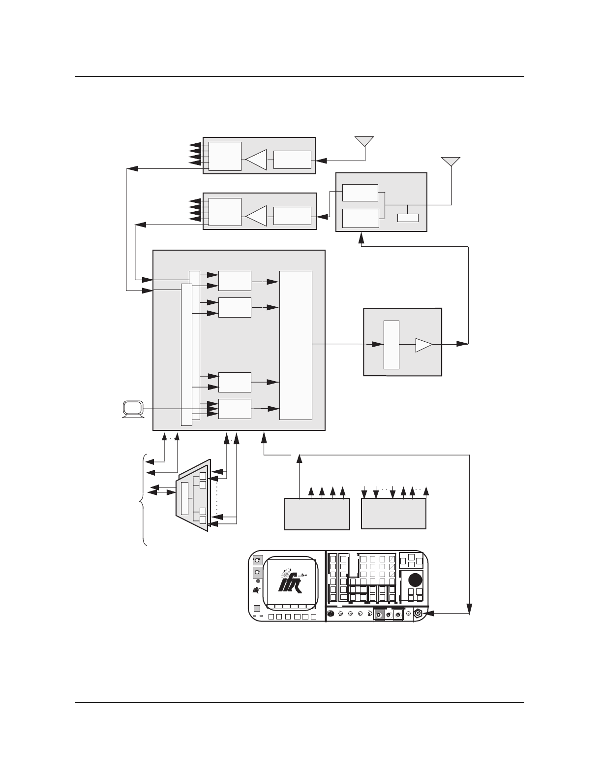
Reference oscillator tests 5-3
Wireless Solutions DualMode 800 Enclosure Maintenance Manual MTX08
Figure 5-1
Oscillator power level and frequency test setup
Diversity Receive
Main
Transmit / Receive
MCPAs
TRU Shelf
Other TRU
Shelves
Other TRU
Shelves LNA Preselect
Filter
Receive Multicoupler
1:8 Splitters
1:8
Splitter
LNA
Duplexer
RX Bandpass
Filter
TX Bandpass
Filter
TRU 8
TRU 2
TRU 7
TRU 1
1:8
Splitter Preselect
Filter
Receive Multicoupler
Integrated
Cellular
Remote
Module
(ICRM)
Data
L
I
N
K
P
P
P
To
MTX
Voice
P
Alarm
Inputs Outputs
Other TRU
Shelves
Alarm
Control Unit
High Stability
MasterOscillator
Data
•••• • •
•••• • •
Communications Monitor (IFR 1600)
INTENSIT
Y
POWER
DUPLEX
OUT
ON
F1 F2 F3 F4 F6F5
MODE
ANTENNA
FM /AM 1600S
AUX
IN
FM/AM
1600S
65W
MAX
65W
MAX
APPLIED
RF
RCVR
DPLX
AF
SCOPE
MTRS
AUTO
SGL
GO
STOP
PRINT
HOLD
SETUP
STORE
0
CE
DEL
8
5
2
SHIFT
RCL
7
4
1
#
^
v
9
6
3
Enter
^
v
+
-
Mu
km
.
TESTCONTROL
DATAENTRY
MEMORY EDIT SQLCH VOL
FIELD SELECT
^
v
< >
^v
< >
MIC/ACC SINAD AUDIO DEMOD VΩCOM AMP SCOPE T/R
IN/OUT IN IN OUT OUT 1KVDC/500V
AC MAX 2 AMPS
MAX
IN
200 VDC
MAX
200W
MAX
IN/OUT
BER
DMM
DATASCROLL
EXT MOD
STEP
SCRN
SCRN
GEN
GEN
ANLZ
Sniffer
VT100
4:1 Combiner
MCPA Shelf
Tx
Combiner

5-4 Master Oscillator tests
411-2051-500 Draft 00.01 November 1999
Oscillator frequency test procedure using TRUs
This test is to be used to test frequency on TRUs:
1. Select and offline a TRU to use for the test.
2. Connect the interface terminal to the RS-232 port on the front panel of the
TRU under test. See Chapter 11, DualMode Radio Unit Tests, in this
manual.
3. Set up TRU for test (refer to Chapter 11 in this manual).
HSMO frequency test — transceiver carrier method
This test ensures that the HSMO is operating at the assigned frequency of 4.8
MHz ±1.2 Hz. See Figure 5-2 for set-up.
Note: The measured frequency deviation from the assigned channel may not
fall within the ±0.25 PPM specification. This is due to the following:
• IFR accuracy at ±0.20 PPM translates to ±175 Hz uncertainty
• a +100 Hz offset to ensure proper baseband operation
These translate into a slightly different deviation measured with the IFR1600:
• -75 to +275 Hz good
• -165 to +365 Hz questionable
• beyond above swap
Step Action Observation
1 Ensure that the communication monitor can
listen to the TRU under test by either the
sniffer or through an antenna.
2 Set the communication monitor to monitor
the forward channel under test.
3 Use the frequency meter/frequency error
meter to measure the offset. ±220 Hz of the assigned frequency
4 Record the assigned frequency (in MHz) and
the frequency error (in Hz) on the test forms.
5 If the results are questionable then repeat for
at least one more transceiver.

Oscillator frequency test procedure using TRUs 5-5
Wireless Solutions DualMode 800 Enclosure Maintenance Manual MTX08
Figure 5-2
Oscillator frequency test setup — transceiver carrier method
Diversity Receive
Main
Transmit / Receive
TRU Shelf
Other TRU
Shelves
Other TRU
Shelves LNA Preselect
Filter
Receive Multicoupler
1:8 Splitters
1:8
Splitter
LNA
Duplexer
RX Bandpass
Filter
TX Bandpass
Filter
TRU 8
TRU 2
TRU 7
TRU 1
1:8
Splitter Preselect
Filter
Receive Multicoupler
Integrated
Cellular
Remote
Module
(ICRM)
Data
L
I
N
K
P
P
P
To
MTX
Voice
P
Alarm
Inputs Outputs
Other TRU
Shelves
Alarm
Control Unit
High Stability
MasterOscillator
Data
•••• • •
•••• • •
Communications Monitor (IFR 1600)
INTENSIT
Y
POWER
DUPLEX
OUT
ON
F1 F2 F3 F4 F6F5
MODE
ANTENNA
FM /AM 1600S
AUX
IN
FM/AM
1600S
65W
MAX
65W
MAX
APPLIED
RF
RCVR
DPLX
AF
SCOPE
MTRS
AUTO
SGL
GO
STOP
PRINT
HOLD
SETUP
STORE
0
CE
DEL
8
5
2
SHIFT
RCL
7
4
1
#
^
v
9
6
3
Enter
^
v
+
-
Mu
km
.
TESTCONTROL
DATAENTRY
MEMORY EDIT SQLCH VOL
FIELD SELECT
^
v
< >
^v
< >
MIC/ACC SINAD AUDIO DEMOD VΩCOM AMP SCOPE T/R
IN/OUT IN IN OUT OUT 1KVDC/500V
AC MAX 2 AMPS
MAX
IN
200 VDC
MAX
200W
MAX
IN/OUT
BER
DMM
DATASCROLL
EXT MOD
STEP
SCRN
SCRN
GEN
GEN
ANLZ
Sniffer
VT100
Tx
Combiner MCPAs
5:1 Combiner
MCPA Shelf

5-6 Master Oscillator tests
411-2051-500 Draft 00.01 November 1999
6-1
Wireless Solutions DualMode 800 Enclosure Maintenance Manual MTX08
Antenna and transmission line tests 6
Antenna direct current continuity
These tests are required for new antennas or antennas suspected of faulty
operation. The tests are service affecting.
The most important consideration of antenna direct current continuity is not
so much the antenna but the transmission line shield. Of course, the antenna
must be electrically connected to the coaxial transmission line, but most
important, the transmission line shield must be grounded for lightning
protection.
The other DC tests serve as more of a record of the resistance of the shield
and center conductor. They may indicate future grounding problems or
identify a change in the antenna dipole condition (open, now shorted or in the
opposite way).
CAUTION
RF Radiation Hazard
All transceiver transmitters must be turned off before
disconnecting or connecting transmit cables to avoid RF
induced injuries.
6-2 Antenna and transmission line tests
411-2051-500 Draft 00.01 November 1999
Antenna return loss
The antenna return loss is measured to verify that the antenna is properly
matched to the system and to identify open connectors.
Antenna return loss test
This test uses the signal generator, the spectrum analyzer and the VSWR
bridge to sweep the antenna for return loss at both the receive (824 to 849
MHz) and transmit (869 to 894 MHz) frequency bands. Figure 6-1 shows the
set up for the test.
Test Equipment: RF Signal Generator
Spectrum Analyzer
VSWR Bridge
If any of the test equipment is not available, a Thruline Wattmeter may be
used (refer to the Thruline Wattmeter Method section).
Step Action Observation
1 Visually inspect the bonding of the
transmission line to the mast ground riser at
both the top and bottom of the tower.
The transmission line must be bonded at
both the top and bottom. A set of binoculars
or a spotting telescope may be required to
verify the upper bonding.
2 Inside the building, measure the DC
resistance of the outer conductor to the
principle ground.
Less than or equal to 0.5 Ω
3 Measure and record the DC resistance of the
center conductor (pin)to the outer
conductor(shield).
4 Also check the alignment of the center pin of
the heliax connector. If necessary re-align
the centre pin so that the female pin in the
antenna jumper cable connector is not
damaged.
Repair or replace heliax, connectors, ground
systems as required.
CAUTION
This test is service affecting when the antenna is disconnected.
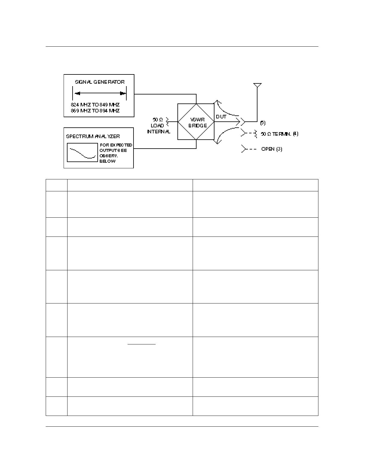
Antenna return loss 6-3
Wireless Solutions DualMode 800 Enclosure Maintenance Manual MTX08
Figure 6-1
Antenna return loss block diagram
Step Action Observation
1 Connect the signal generator, the spectrum
analyzer and a 50 ohm load to the VSWR
bridge.
See Figure 6-1.
2 Set the signal generator output level to 0
dBm.
3 With the device under test (DUT) VSWR
bridge port connected to an open, adjust the
display on the spectrum analyzer to the top
of the screen.
4 Connect a 50 ohm termination to the open
port on the VSWR bridge and step the
generator through the receive and transmit
band to verify the test set-up for return loss.
Return loss should be greater than 35 dB
over the bands.
5 Remove the termination from the VSWR
bridge, connect the antenna jumper cable to
the open port and again step the generator
across the transmit and receive bands.
6 Record the minimum return loss of the
antenna and transmission line in the system. Return loss:824 to 849 MHz RX
869 to 894 MHz TX
Greater than or equal to
14.5 dB + (2 x TX line loss)
7 Repeat the test for each antenna installed for
the cell site.
8 If the test fails, check the antenna matching,
cables and connectors.

6-4 Antenna and transmission line tests
411-2051-500 Draft 00.01 November 1999
Thruline wattmeter method (Antenna return loss)
This is a service affecting test using a Thruline Wattmeter. It can be used with
transmit antennas only. Ensure that all transmitters are OFF before
inserting the Thruline in the transmission path.
Antenna sweep
This is a service affecting test. Ensure that all transmitters are OFF before
disconnecting the antenna cable.
Step Action Observation
1 Connect the Thruline between the duplexer
and the antenna.
2 Measure the forward and reverse power
using the appropriate element with one or
more transmitters turned on.
Reflected power less than 4% of forward
power
Step Action Observation
1 Set up and calibrate a network analyzer
(HP8753C or equivalent) to sweep 823 to
895 MHz.
2 Notify the Control Center to OFFLINE the
cell site.
3 Disconnect the antenna jumper cable.
(Located at the duplexer for the tx/rx antenna
or at the RMC for the diversity receive
antenna.)
- continued -

Antenna sweep 6-5
Wireless Solutions DualMode 800 Enclosure Maintenance Manual MTX08
4 Perform a return loss sweep on the Network
Analyzer. Note the worst frequencies by
placing 2 markers each on the transmit and
receive frequencies. then print a hard copy of
the upper left quadrant.
Measured return loss of the antenna can be
calculated as:
RL (ant) = -14 dB - 2 times the antenna
cable loss
or:
Compare you results with that of the RF Path
calculated return loss of the cell site logbook
(check the RF PAth Analysis sheet).
If the results are bad compared to the log
book values connect the test cable directly to
the main transmission line and resweep.
It is possible to have a bad jumper. If the
result s are still bad then the problem could
be either with the transmission line or the
antenna.
5 Do a TDR sweep of the antenna. Print a hard
copy of the lower left quadrant.
6 Do a SWR sweep of the antenna. Print a
hardcopy of the upper quadrant. The result
should not be higher than 1.5:1
7 Do a Smith Chart of the antenna. Print a
hard copy of the lower right quadrant. The
results must be close to 50 ohms (±50
ohms).
8 Reconnect all the jumpers to their proper
location then inform the Control Center to
RTS the Cell Site.
If the transmit antenna is bad and the receive
antenna is good on the transmit band,
restore service by using the receive antenna
until the transmit antenna is repaired.
- End -
Step Action Observation

6-6 Antenna and transmission line tests
411-2051-500 Draft 00.01 November 1999

7-1
Wireless Solutions DualMode 800 Enclosure Maintenance Manual MTX08
Enhanced Receive Multicoupler (ERMC)
tests 7
ERMC description
The Enhanced Receive MultiCoupler (ERMC) modifies the receive RF signal
for the front-end of the TRU shelf transceivers. The ERMC provides
selectivity, signal gain and signal distribution so that the receive signal is
adequate for the transceiver front-end.
ERMC overall gain measurement test
This test is required for a cell site suspected of faulty operation. The test is
service affecting.
Step Action Observation
1 Notify the Control Center to OFFLINE the
cell site.
2 Disconnect the antenna feed cables from the
selectivity filter inputs.
3 Disconnect the cable from the ERMC splitter
port to be tested.
4 Using a 50-ohm cable, connect the
communications monitor Duplex Output port
to the selectivity filter input of the ERMC
(either A or B side). See Figure 7-1.
5 Using a 50-ohm cable, connect the
communications monitor T/R port to one of
the splitter ports corresponding to the A or B
path selected. See Figure 7-1.
- continued -

7-2 Enhanced Receive Multicoupler (ERMC) tests
411-2051-500 Draft 00.01 November 1999
Note: If an irregularity in the ERMC gain exists, call Nortel Networks RF
Engineering Support for assistance.
6 Set up the communications monitor to output
an RF signal less than -60 dBm sweeped
from 824 to 849 MHz.
7 Using the communication monitor in
spectrum analyzer mode sweep the RMC
and note any irregularities in the gain.
Gain measured may vary depending on cell
site requirements for RF sensitivity versus
IMD. See the
RF Engineering Guidelines for
800 MHz Cellular Systems
, 411-2131-007.
8 Repeat for all splitter ports and for both A
and B diversity paths.
9 Replace the antenna feed and splitter output
cables and then inform the Control Center to
RTS the Cell Site.
- End -
Step Action Observation
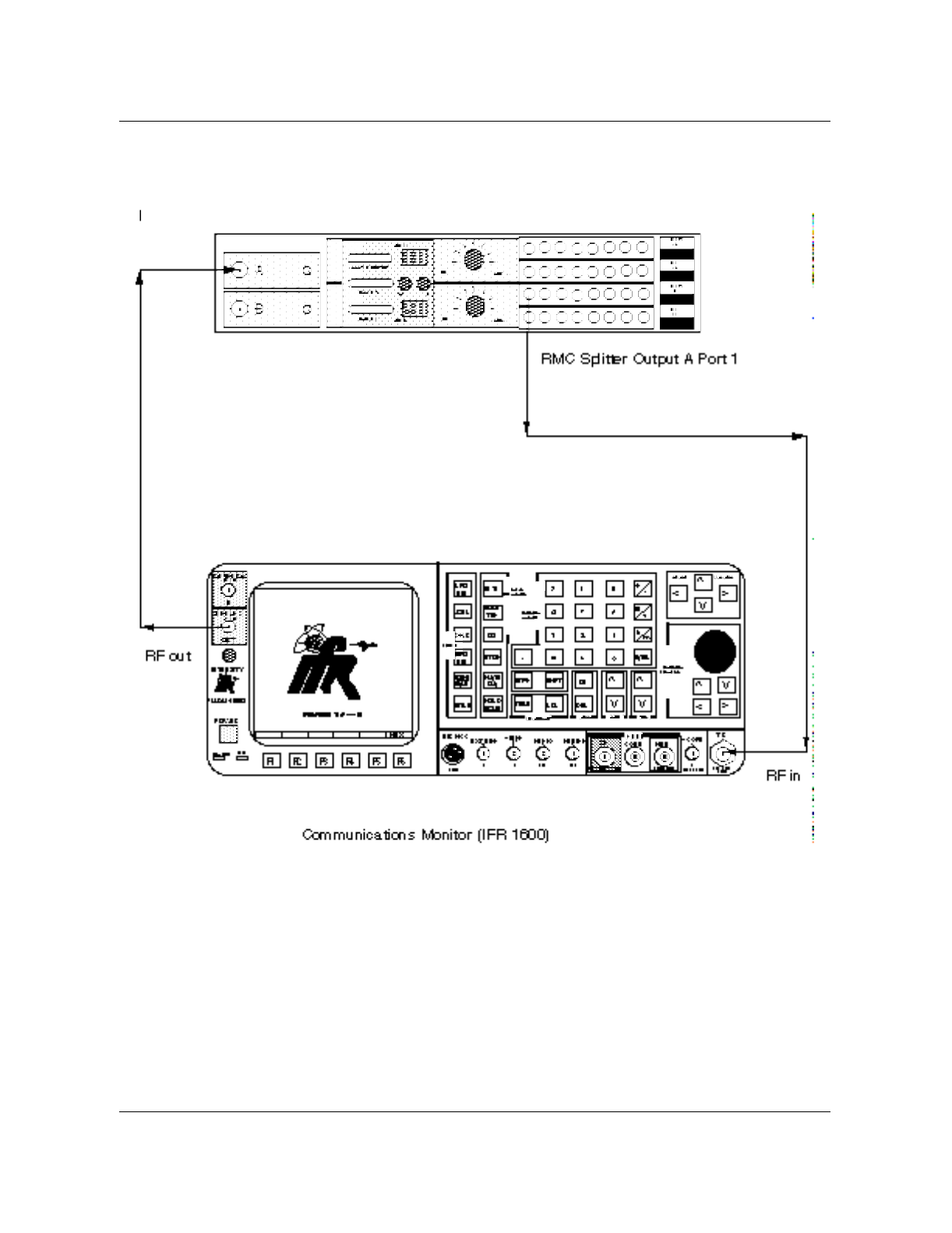
ERMC overall gain measurement test 7-3
Wireless Solutions DualMode 800 Enclosure Maintenance Manual MTX08
Figure 7-1
RMC overall gain measurement test
RMC Input Preselect Filter A
7-4 Enhanced Receive Multicoupler (ERMC) tests
411-2051-500 Draft 00.01 November 1999
ERMC gain adjustment
This section refers to the RF Engineering Guidelines for 800 MHz Cellular
Systems, 411-2131-007, specifically the Talk-in Talk-out (TITO) adjustment.
Gain setting are factory preset to 16 dB but specific cell site requirements
may differ. Refer to the 800 MHz ERMC Deployment Guide, 411-2131-940,
for more information on the ERMC.
Note: Use caution when attempting to adjust the ERMC variable
attenuator. Overall system performance may suffer seriously, therefore a
thorough understanding of the RF Engineering Guidelines should be
acquired.
Talk-In/Talk-out (TITO) balance test
The main purpose of the Talk-In/Talk-Out (TITO) test is to ensure that the
ERMCs are tuned correctly. If they are not, the user could get noisy channels
usually due to co-channel interference, low RF levels, or both. This usually
happens to sites with large coverage where the multicoupler does not have
sufficient gain to balance to talk-in path.
This test is required when there is a problem with the receive path and the
ERMCs are suspected of faulty operation.
If the ERMCs are suspected to be faulty this test will verify if they actually
are. There are two tasks that are done at the same time with this test after a
call has been set-up.
1. You are monitoring a channel and RSSI (Receive Signal Strength
Indicator) from the mobile.
2. You are monitoring the same channel and RSSI at the cell site.
Figure 7-2 shows the call setup for a TITO balance test.
CAUTION
Service affecting
This test is service affecting and will take two TRU Radios off
line. This test should be done when there is a problem; not as a
regular maintenance routine.
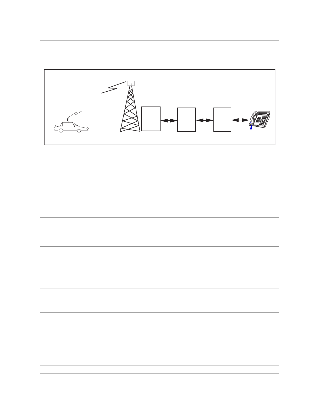
Talk-In/Talk-out (TITO) balance test 7-5
Wireless Solutions DualMode 800 Enclosure Maintenance Manual MTX08
Figure 7-2
Talk-In/Talk-out call setup
In order to guarantee minimum noise and reflection, the mobile should be in
about the middle of the cell’s coverage area, away from any tall buildings or
shadow zones from hills or mountains.
TITO test procedure
Step Action Observation
1 At the MTX place an idle TRU in the off-line
state. The TRU will be in the idle state.
2 Make a call from the mobile to a phone at the
switch and leave phone off hook. Switch end will receive a call from the mobile
to setup a call for monitoring.
3 At the cell site test TRU, connect a terminal
and place in the debug mode. See Terminal
Interface Operation in Chapter 1.
4 When the call has been setup put the mobile
into monitor mode and take note of the RSSI
measurements.
Record the RSSI measurements at the
mobile.
5 Set the test TRU, to the same channel as the
one with the call on it from the mobile. TRU will display same channel.
6 Set the TRU up to monitor the RSSI
measurements. See RSSI tests for set up in
Chapter 11 of this manual.
This turns on all antenna ports.
- continued -
MTX DMS
Cell site
Equipment
Mobile Monitoring
RSSI

7-6 Enhanced Receive Multicoupler (ERMC) tests
411-2051-500 Draft 00.01 November 1999
Note: If an imbalance exists, call Nortel Networks RF Engineering
Support for assistance in re-balancing the ERMC output.
Always ensure that the site is balanced for the worst case. The radio TX path
must be equal to or stronger than the Talk-In path. If there are significant
differences in the Talk-out (base TX) levels on different antennas, check for a
defective RF component such as an antenna, a cable, or a combiner.
7 Monitor and record 20 RSSI measurements
simultaneously at both the mobile and the
test TRU. The mobile should be driven
through a predetermined path to repeat the
test for other channels available.
Record and average the levels in the chart.
- End -
Step Action Observation

8-1
Wireless Solutions DualMode 800 Enclosure Maintenance Manual MTX08
Alarm Control Unit (ACU) tests 8
Overview
The Alarm Control Unit (ACU) provides discrete alarm monitoring, reporting
and control functions at a cell site. The site ACU concentrates all alarm input
points at the cell site and updates the MTX of any status change over
redundant data links. The MTX can also poll for the condition of the ACU
and request current status information or change the status of any output
control contact. For a complete description of the ACU, refer to the
DualMode 800 Enclosure Functional Description, 411-2051-100.
Alarm Control Unit test setup
Connect a VT100 terminal (or equivalent) using a null modem cable to the
ACU local terminal connector.
Step Action Observation
1 Set up the terminal as per the requirements
to the right. BAUD Rate: TX 9600
RX 9600
Scroll: smooth
Auto repeat: on
ANSI
Auto Wrap: off
Receiver Parity: ignore
Parity: disabled
Character Bits: 8 bits
Interface: on
Scroll Key: VT100
Form Feed: line feed
Control Characters: executed
Local Echo: off
RTS-CTS Handshake: off
8 Bits Tx: space
- continued -
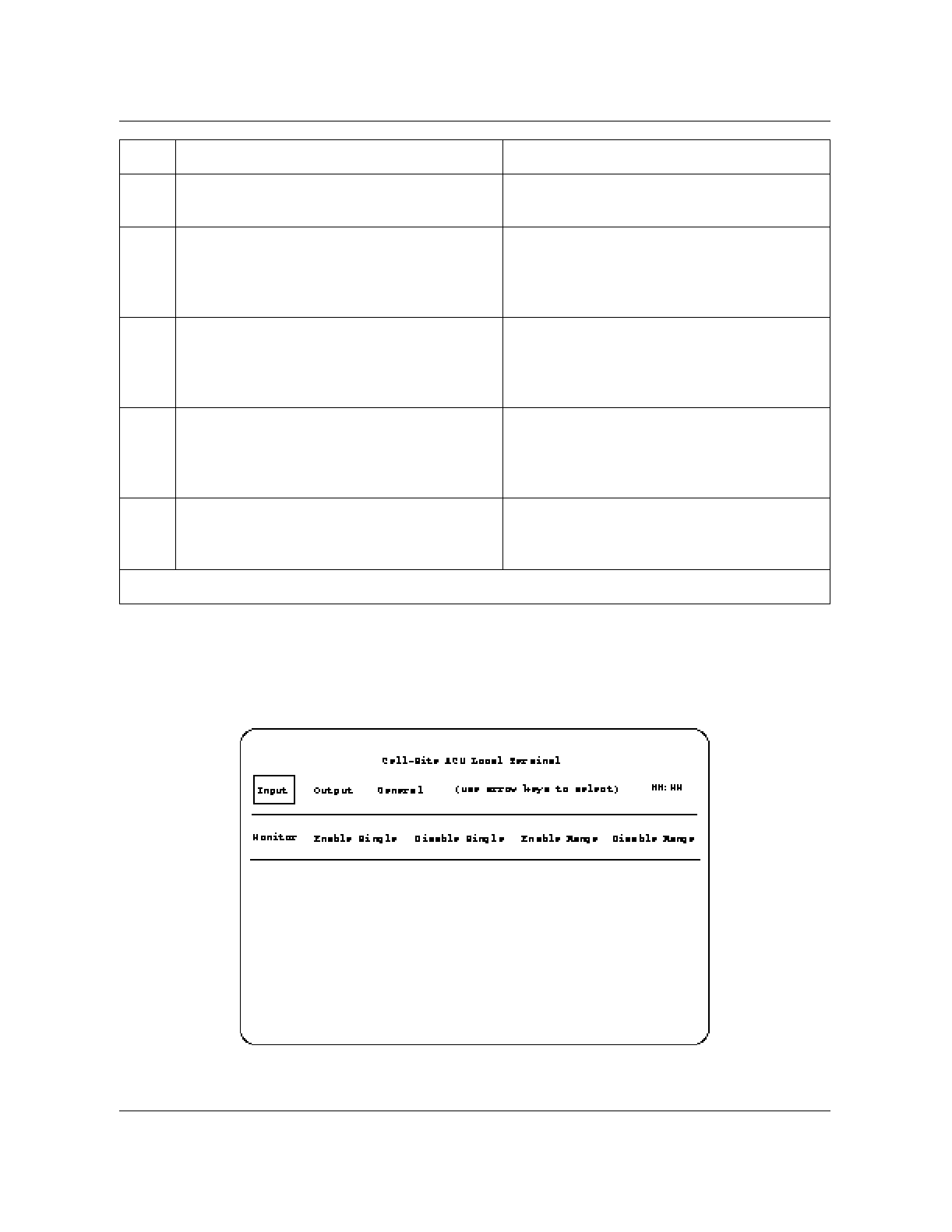
8-2 Alarm Control Unit (ACU) tests
411-2051-500 Draft 00.01 November 1999
Figure 8-1
ACU First maintenance screen
2 Press the RESET key on the ACU to activate
the Maintenance Screen on the terminal. The ACU Maintenance Screen as per the
following diagram Figure 8-1 will appear.
3 Using the keyboard arrows, select the Input
and Monitor menu items on the screen.
Verify the remote alarms with respect to the
site alarm records.
See Chapter 1,
Equipment operation
, for a
description of all the menus.
4 Test all equipped alarm points on the ACU.
This can be done by performing action such
as turning DC breaker OFF, removing fuses,
opening doors.
Bold display - alarm ON
Normal display - alarm OFF
5 Apply +27 Vdc to each equipped alarm input
at the rear of the ACU. Verify that each alarm
indicates the correct status on the VT100
screen.
Bold display - alarm ON
Normal display - alarm OFF
6 Open and close each selected output and
verify its action by observing an open or
short on the rear output connector, J8.
- End -
Step Action Observation
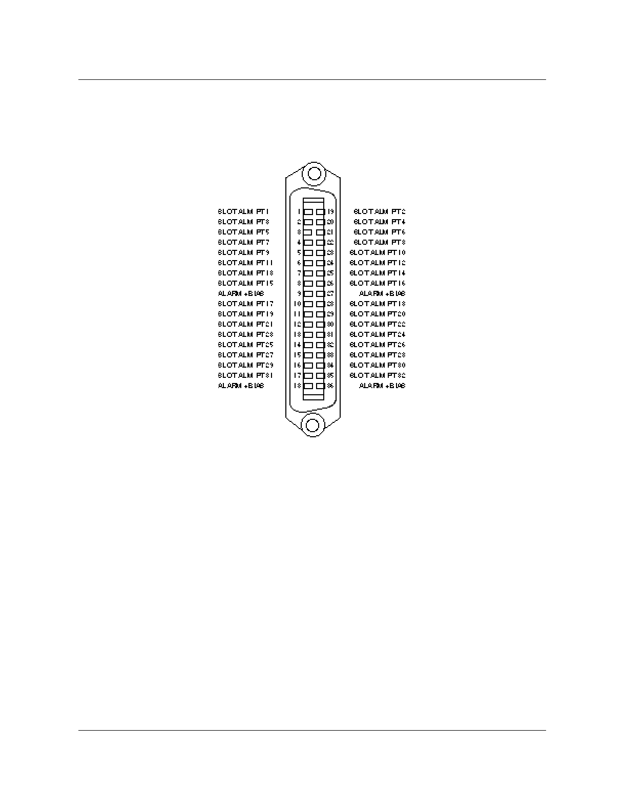
Alarm Control Unit test setup 8-3
Wireless Solutions DualMode 800 Enclosure Maintenance Manual MTX08
Figure 8-2 shows the pin assignments of a typical alarm connector.
Figure 8-2
Typical alarm connector (36-Pin)

8-4 Alarm Control Unit (ACU) tests
411-2051-500 Draft 00.01 November 1999

9-1
Wireless Solutions DualMode 800 Enclosure Maintenance Manual MTX08
Performing tests using a DCSM 9
Introduction
The DualMode Cell Site Monitor (DCSM) can operate in either stand-alone
mode or directed mode. In stand-alone mode, the handset on the front panel is
used to conduct manual calls. In directed mode, the MTX assumes control of
the DCSM to perform a variety of non-obtrusive tests of the site. The MTX
directed tests on the CCH, VCH, and LCR can be invoked from the respective
level of the MAP position. Additionally from the CTT level VCH tests can be
initiated with the option of testing a number of Devices Under Test (DUT) in
sequence. The tests can also be set-up to be automatically run using the
scheduler feature of Table CTTSCHED.
By making a call to the DCSM in the stand-alone mode or performing tests at
the MTX in the directed mode, the Control Channel (CCH) and Voice
Channels (VCH) of a cell site can be verified to be operating correctly.
Stand-alone mode tests
In stand-alone mode the mobile unit in the DCSM functions in the same
manner as a subscriber mobile telephone in the cellular system. For this
reason, the mobile unit in the DCSM has to be activated in the same manner
as a subscriber mobile telephone. The cellular system will not recognize the
mobile unit or allow it to function unless the programming on the Numerical
Assignment Modules (NAM) is completed. Refer to Chapter 1, Cell site
operation, for the programming of the NAMs.
In stand-alone mode the DCSM acts as a subscriber mobile registered in the
partition. Once the mobile of the DCSM has acquired and locked onto a CCH
in the partition it can be used to make a call through test through the handset
of the mobile. Making a call verifies that the system is up and running.
Stand-alone ACCH/DCCH selection
When a partition is equipped with both an ACCH and a DCCH do the following:
1. select NAM 4 and enter the programming selection mode

9-2 Performing tests using a DCSM
411-2051-500 Draft 00.01 November 1999
2. scroll to the ScnDCCH field
— if you want to verify the ACCH set ScnDCCH to 0 or
— if you want to verify the DCCH set ScnDCCH to 1
Note: In ScnDCCH mode you should set the field 1STDCCH to the
channel number of the DCCH you wish to perform the call through test
on. If you have a sectored site you must repeat the NAM programming for
each specific DCCH you wish to perform the stand-alone call through
test.
DCSM auto answer facilities
In both the directed or stand-alone modes the DCSM will automatically
answer all incoming calls. If the incoming call uses an analog call resource
(AVC), the DCSM will generate a 1004 Hz tone for five seconds on the
reverse path. The forward audio will then be looped to the reverse audio for
the remainder of the call. If the incoming uses a TDMA call resource (DTC),
the DCSM will automatically answer the incoming call, but will not generate
a tone, or loop the forward and reverse audio paths.
Nortel Networks recommends that the MRLT, MRHT, MRLP and MRLR
VCH tests be used for verifying the performance of analog voice channels.
Performing tests using the DCSM in the directed mode
The directed-mode tests using the DCSM can be further divided into two
categories:
• MTX trunk tests
• Control channel tests
Control channel testing uses the DCSM to monitor the Overhead Message
Train (OMT) on the ACCH and the FBCCH and EBCCH sub channels on a
DCCH. A site control channel can also be tested for its power level in both the
forward and reverse direction.
MTX trunk tests use the DCSM mobile as a loop-around to measure various
indicators of the trunk path performance. Specifically the RF performance of
the DUT can be measured by advantageously using the parameters of Table
CTTPARMS.
Monitoring functions
With the MON ON command from the CTU MAP level, you may enable the
ICP to drive the periodic CCH audit order function. Command parameters
specify if a cell or a particular cell/sector is to be monitored. You must also

Performing tests using the DCSM in the directed mode 9-3
Wireless Solutions DualMode 800 Enclosure Maintenance Manual MTX08
specify if monitoring is to be performed for ACCHs, DCCHs, or both. In the
event that both CCH types are required to be monitored, the periodic audit
will proceed in a round robin fashion by first monitoring all the ACCHs
within the scope of the command, and then all the DCCHs.
When a DCSM is monitoring an ACCH, it detects:
a. loss of CCH synchronization
b. SID errors
c. mismatches between the CCH onto which the ICP commanded the
cell site monitor to lock and the CCH onto which the cell site monitor
is locked
When a DCSM is monitoring a DCCH, it also detects:
a. errors in the number of F-BCCH slots
b. errors in the number of E-BCCH slots
c. errors in the E-BCCH RCI locked
These errors are communicated to the CM as unsolicited messages.
When MON is ON, the ICP periodic audit process entails commanding the
DCSM to monitor the current CCH in sequence. Once the DCSM mobile is
locked onto the CCH, the ICP commands an audit order to be issued over the
CCH. If the audit order response is not received over the reverse CCH, then a
retry is attempted. Two consecutive failures results in the ICP reporting an
unsolicited audit order failure message to the CM. The message type
identifies either the CCH or the DCSM as the suspected cause of the failure.
OMs are consulted to determine if originations, or page responses, or
registrations were occurring during the period of the audit for the CCH under
test. If these OMs were being incriminated, then a failure of the DCSM is
presumed, otherwise a failure of the CCH is presumed.
If the DCSM mobile does not successfully lock onto the CCH, a new
unsolicited message is sent to the CM with a message type indicating the
failure to synchronize.
The goal is to revisit each CCH approximately every two minutes.

9-4 Performing tests using a DCSM
411-2051-500 Draft 00.01 November 1999
Posting the DCSM
To use the DCSM to perform tests requires that the DCSM is in service
(INSV) state. The DCSM can be posted before a test is initiated from the
Maintenance and Administration (MAP) terminal (see Procedure 9-1).
Control Channel tests
The Digital or Analog Control Channel can be monitored and tested using the
DCSM located in the same partition in which the DCCH/ACCH serves.
The following tests are available from the MTX MAP position.
CCH MAP level:
• forward DCCH/ACCH RF power measurement (POWER)
• reverse DCCH/ACCH RF power measurement (RSSI)
• ACCH Overhead Message Train monitoring (CCHOMT)
• DCCH F-BCCH and E-BCCH parameter reporting (DCCHPARM)
CTU MAP level:
• Background round robin monitoring (MON)
Procedure 9-1
Posting the DCSM
Step Action Observation
1 At the MAP terminal, post the DCSM by entering:
>MAPCI;MTC;MTX;CELL <cell_number>
>CTU;POST <DCSM_number>
2 Ensure that the posted DCSM is in the INSV (in service) state. If
not, place the DCSM to the INSV state by entering:
>BSY;RTS

Performing tests using the DCSM in the directed mode 9-5
Wireless Solutions DualMode 800 Enclosure Maintenance Manual MTX08
Preparing for Control Channel tests
Before any of the Control Channel tests can be invoked from the MAP
terminal, the DCSM as well as the DCCH or ACCH to be tested must be
posted. The Control Channel test setup is described in Procedure 9-2.
Note: For MTX04 monitoring only needs to be invoked to run the CCH
power test. For earlier MTX releases, monitoring must be invoked for all
CCH tests.
Procedure 9-2
Control Channel test set-up
Step Action Observation
1 At the MAP terminal, post the DCSM by entering:
>MAPCI;MTC;MTX;CELL <cell_number>
>CTU;POST <DCSM_number>
2 Make sure that the posted DCSM is in the INSV (in service) state.
If not, place the DCSM to the INSV state by entering:
>BSY;RTS
3 Post the Control Channel to be tested by entering:
>CCH;POST <channel_number>
4 Make sure that the posted CCH is in the INSV state. If not, place
the CCH to the INSV state by entering:
>BSY;RTS
5 If the DCSM is in a sectored configuration, force the DCSM to scan
the DCCH of the sector that is to be tested by entering:
>MON ON <x, y, z, u, v, or w>,<A,D,BOTH>
(Sector Designation) (ACCH, DCCH, or Both)
For example: >MON ON X D (You must only monitor the CCH
under test)
A = monitor ACCH
only
D = monitor DCCH
only
Both = monitor both
CCH types through
background
monitoring
6 The DCSM is now ready to test the desired CCH.

9-6 Performing tests using a DCSM
411-2051-500 Draft 00.01 November 1999
Measuring Forward Control Channel RF power
The DCSM can be directed to take a Power measurement on the currently
active CCH. Raw RSSI readings are returned from the DCSM and are
translated into dBm at the CM. Procedure 9-3 is used to test the forward
power.
Measuring Reverse Control Channel power
For this test the DCSM is directed to terminate a call. The MTX then directs
the CCH to measure the TX power of the DCSMs page response (RECC or
RACH). The readings are in a raw format and are translated into dBm at the
CM. Procedure 9-4 is used to test the reverse power.
Procedure 9-3
Measuring forward CCH RF power
Step Action Observation
1 Make sure that the DCCH and the DCSM have been posted and
are in the INSV state as per the Control Channel Test Setup
Procedure.
2 At the CCH LEVEL OF THE MAP, enter:
>TST POWER
Procedure 9-4
Measuring reverse CCH RF power
Step Action Observation
1 Make sure that the DCCH and the DCSM have been posted and
are in the INSV state as per the Control Channel Test Setup
Procedure.
2 At the CCH LEVEL OF THE MAP, enter:
>TST RSSI

Performing tests using the DCSM in the directed mode 9-7
Wireless Solutions DualMode 800 Enclosure Maintenance Manual MTX08
Round Robin Monitoring
The MON command is executed from the CTU level of the MAP position
with a posted INSV DCCH or ACCH.
The MON command forces the DCSM to scan specific CCHs as specified in
the command options.The MON command sequence is as per Procedure 9-5.
Procedure 9-5
Round Robin Monitoring
Step Action Observation
1 Make sure that the DCCH or ACCH and the DCSM have been
posted and are in the INSV state as per the Control Channel Test
Setup Procedure.
2 If the DCSM is in a sectored configuration, force the DCSM to scan
the DCCH of the sector that is to be tested by entering:
>MON ON <x, y, z, u, v, or w>, <A,D,BOTH>
(Sector Designation), (ACCH, DCCH, or Both)
A = monitor ACCH
only
D = monitor DCCH
only
Both = monitor both
CCH types
3 Example: MTX120 JUL04 12:12:30 1123 INFO Terminal
Maintenance Event
CELL 15 CTU 0 PRTN: Y
EVENT: Unsol Wrong CCH
REASON: CCH Number Wrong

9-8 Performing tests using a DCSM
411-2051-500 Draft 00.01 November 1999
Querying ACCH OMT parameters
The DCSM can also be queried for the latest ACCH OMT parameters (see
Procedure 9-6).
Querying FDCCH parameters
The DCSM can also be queried for the latest F-BCCH and E-BCCH
parameters (see Procedure 9-7). Reported parameters include all mandatory
F-BCCH and E-BCCH messages. This test is only valid for IS-136.1 DCCHs.
Procedure 9-6
Querying ACCH OMT parameters
Step Action Observation
1 Make sure that the ACCH and the DCSM have been posted and
are in the INSV state as per the Control Channel Test Setup
Procedure.
2 At the ACCH level of the MAP position enter:
>TST CCHOMT
3 The system responds by displaying the information on the MAP
terminal. Check the log values reported against the system datafill. Results displayed on
MAP terminal.
Procedure 9-7
Querying the DCSM parameters
Step Action Observation
1 Ensure that the DCCH, VCH and the DCSM have been posted and
are in the INSV state as per the Control Channel Test Setup
Procedure.
2 At the DCCH level of the MAP position enter:
>TST DCCHPARM <option>{F,E,ALL}
Options:
F - request is for
FBCCH parameters
E - request is for
EBCCH parameters
ALL - request is for
FBCCH and EBCCH
parameters
3 The system responds by generating an MTX170 log. Check the log
values reported against the system datafill.

Performing tests using the DCSM in the directed mode 9-9
Wireless Solutions DualMode 800 Enclosure Maintenance Manual MTX08
MTX CTT tests
MTX CTT (Cellular Terminal Tests) tests use the DCSM as a test mobile to
test AVCHs by looping around a tone generated by the MTX Trunk Test
Terminal (TTT). These tests measure the performance of the specified AVCH
and associated trunks. The performance criteria measurable are:
• wireline trunk audio performance (loss) and associated noise
(MALT, MAHT)
• wireless trunk RF performance (loss) and associated noise
(MRLT, MRHT)
• forward and reverse RF strength performance (MRLP, MRLR)
• system call set-up capability (MTRM, DTRM)
Naming conventions
All MTX trunk tests use a four letter acronym to describe the functionality of
the test. Each letter of the test acronym is explained in Table 9-1.
MTX Audio Low Test and MTX Audio High Test (MALT/MAHT)
This test does not require a DCSM. The MALT and MAHT test measures the
following MTX trunk parameters:
• far-to-near-loss
• loop loss
• loop noise
Table 9-1
Naming convention of the MTX trunk tests
Letter # Designation
1 M = MTX — test a MTX VCH trunk
D = DCCH — set-up VCH trunk
2 A = Audio — test the audio link of the trunk
(DCSM is not a requirement)
R = RF — test the RF link of the trunk
3 L = Low — use a low level tone for the test
H = High — use a high level tone for the test
4 T = Transmission — measure transmission loss and
noise
R = Receiver — measure the reverse RF power level
of the VCH
P = Power — measure the forward RF power level of
the VCH
Note:
DTRM and MTRM violate this naming convention.
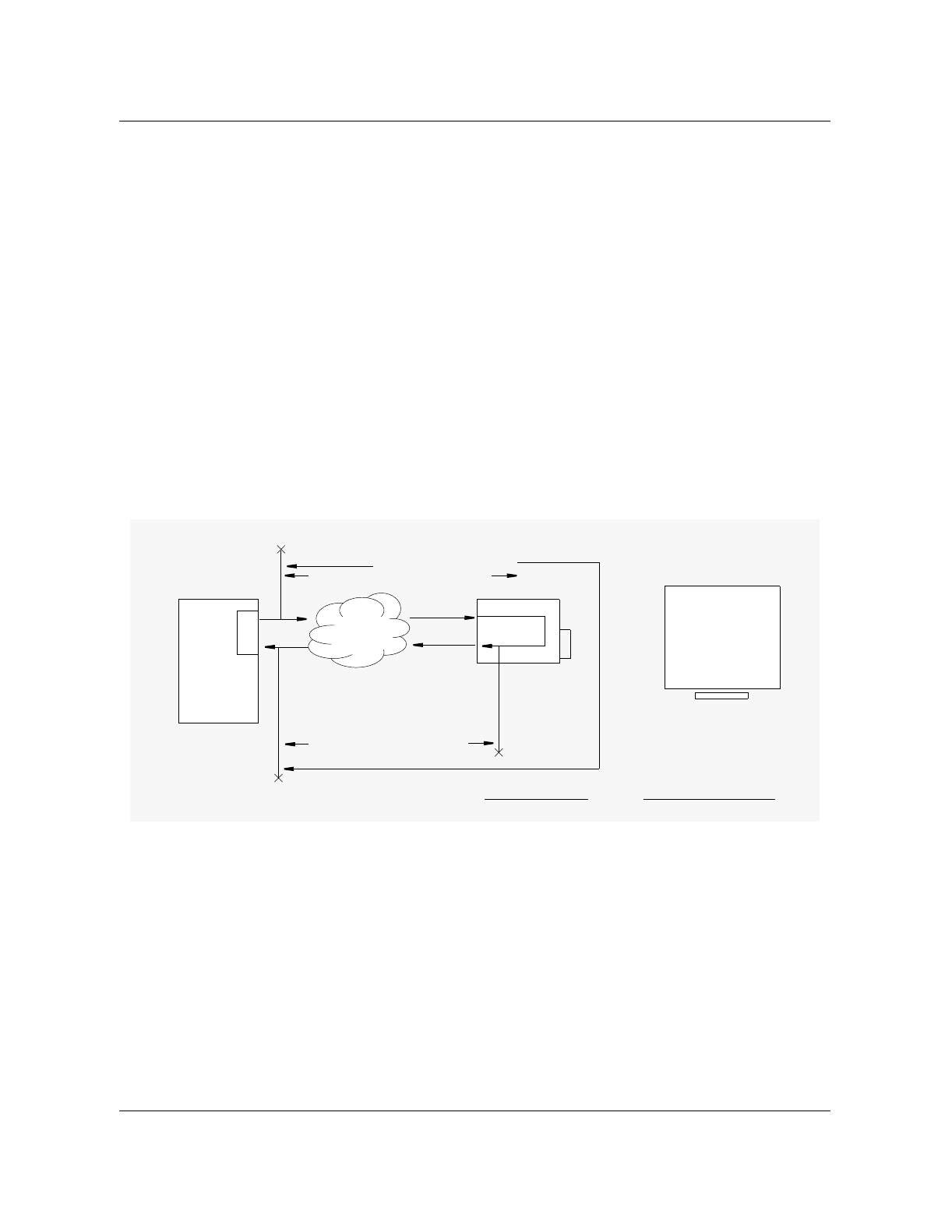
9-10 Performing tests using a DCSM
411-2051-500 Draft 00.01 November 1999
The MALT and MAHT tests can be invoked in the following ways:
• from a posted transceiver at the VCH MAP level
• from the CTT level (the first available VCH is selected)
• automatically using Table CTTSCHED (also selects first available VCH)
The MALT and MAHT test use the TTT to inject a low and high level (the
level and frequency is determined by the CTTPARMS tuple) audio tone
respectively onto the MTX trunk. The audio tone is looped from the forward
to the reverse audio by the DUT (that is, the TRU) located at the cell site and
the returned level is measured by the TTT. The TTT also makes a
measurement of the noise level accompanying the audio signal at the return
end of the loop. The MALT and MAHT tests do not use the DCSM as part of
the test path. Figure 9-1 shows the test path and the measured path
measurements.
Figure 9-1
MALT and MAHT CTTPARMS Fields
Running the MALT and MAHT test
Before either the MALT or MAHT test is run be sure that the appropriate test
parameters are datafilled in Table CTTPARMS.The MALT test is invoked at
the VCH level of the MAP position on a posted channel. Procedure 9-8 lists
the step by step manual method of invoking the MALT and MAHT tests.
DCSM
DUT
TTT
Loop Loss (measured)
NM Network
DRU or BST
Far-to-near loss (measured)
Tone injected
Tone measured
and Loop Noise
level (dBrn)
(MTX Switch)
Cell Site
()
Near to Far Loss (Calculated)

Performing tests using the DCSM in the directed mode 9-11
Wireless Solutions DualMode 800 Enclosure Maintenance Manual MTX08
Figure 9-2
MALT Test Output MTX303 Log
Refer to the DualMode 800 Enclosure Troubleshooting Guide, 411-2051-900,
for more information of the fields in MTX303 Log. Below are the descriptions
of the fields of MTX303 which give the actual measure results:
LP_LOSS - The Loop Loss measured in dB
FN_LOSS - The Far-to-Near Loss in dB, calculated from LP_Loss - NF_Loss
NF_LOSS - The Near-to-Far Loss measured in dB
NOISE - The Loop Noise Level measured in dBrn
Figure 9-3
MAHT Test Output MTX303 Log
Procedure 9-8
Initiating the MALT/MAHT test
Step Action Observation
1 Go to the MAP level of the MTX radio (VCH) to be
tested:
(example) MAPCI;MTC;MTX;CELL 100;VCH
2 Post the radio to be tested:
(example) POST 2
3 Invoke the MALT/MAHT test on the posted radio:
TST MALT or TST MAHT
The MTX will indicate that the test is
underway.
4 Wait for the results of the MALT/MAHT test. The
MTX will display them once the test is complete. See Figure 9-2.
5 If the results fail check that the CTTPARMS fields
are correctly datafilled. Then repeat the test to
verify the failure.
MTX303 JUN29 12:12:12 2500 CTT TRANSMISSION TEST
CELL: 20x TEST: MALT VCH: 10 HW: DRU PASS
PA_EML: -20 dB LP_EML: -20dB TONE: 10 dBm
LP_LOSS: 0.0 dB FN_LOSS: -0.3 dB NF_LOSS: 0.3 dB
NML: 25 dB NIAL: 30 dB NOISE: 21 dBRN
MTX303 JUN29 12:12:12 2500 CTT TRANSMISSION TEST
CELL: 20x TEST: MAHT VCH: 10 HW: DRU PASS
PA_EML: -20 dB LP_EML: -20dB TONE: 10 dBm
LP_LOSS: 0.0 dB FN_LOSS: -0.3 dB NF_LOSS: 0.3 dB
NML: 25 dB NIAL: 30 dB NOISE: 21 dBRN

9-12 Performing tests using a DCSM
411-2051-500 Draft 00.01 November 1999
Troubleshooting action
If the test fails then it should be repeated for verification. Should the test still
fail the following hardware components may be at fault:
• the TRU
• ICRM packs (the AX50s, AX47s, AX87s)
• the T1 transmission equipment used
• the ICP cards (the AX50s)
The signal may be rerouted to eliminate and pinpoint faulty hardware
components, or the equipment may be swapped one at a time with known
good units and the test repeated. When the test passes the faulty unit may have
been found.
The MTX RF Low and High Tests (MRLT and MRHT)
The MTX RF Low and High tests measure an audio tone which has been looped
at the DCSM. The test verifies the RF path on the forward and reverse links of
the DUT. The test therefore verifies the RF portion of the circuit. The MRLT
test measures the following three parameters of the circuit:
• the Loop Loss
• the Loop Noise
• the Path Far-to-Near Loss
The MRLT and MRHT tests can be invoked in the following ways:
• from a posted transceiver at the VCH MAP levels
• from the CTT level (all available VCH are tested starting with the first
available)
• automatically using Table CTTSCHED (this also selects the first available
VCH)
Once the test is invoked a call is terminated to the DCSM mobile. The DCSM
then transmits a 1004 Hz tone at 2.9 kHz deviation for 5 seconds, after which
the FWD audio is looped to the REV audio. The TTT then transmits a tone
(level and frequency determined in Table CTTPARMS) which is transmitted
on the forward RF path by the DUT to the DCSM. The DCSM subsequently
loops the forward audio to the reverse audio and transmits the tone to the
DUT through the reverse RF path. The returned audio is finally measured by
the TTT. The values measured are returned in the log report which is
subsequently reported to the technician at the MAP terminal through MTX
Log 303. Figure 9-4 shows the test path and the measured path measurements.
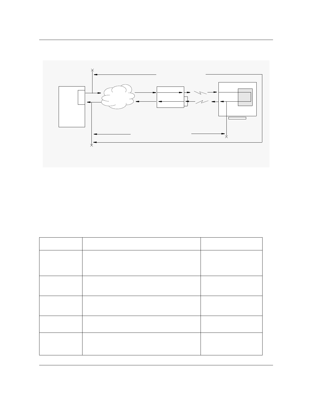
Performing tests using the DCSM in the directed mode 9-13
Wireless Solutions DualMode 800 Enclosure Maintenance Manual MTX08
Figure 9-4
MRLT and MRHT CTTPARMS fields
How to Invoke the MRLT/MRHT test
Before the test is run the appropriate CTTPARMS tuple must be datafilled
with the correct values. With the CTTPARMS tuple correctly datafilled and
selected through CTTGROUP the test may be initiated either manually from
the MAPCI level (VCH or CTT) or automatically using CTTSCHED.
Procedure 9-9 outlines the manual method of invoking the MRLT and MRHT
tests.
Procedure 9-9
Initiating the MRLT/MRHT tests
Step Action Observation
1 Go to the MAP level of the MTX radio (VCH) to be
tested:
(example) MAPCI;MTC;MTX;CELL 100;VCH
2 Post the radio to be tested:
(example) POST 2
3 Invoke the MRLT/MRHT test on the posted radio:
TST MRLT or TST MRHT
The MTX will respond
that the test is underway.
4 Wait for the results of the MRLT/MRHT test. The
MTX will display them once the test is complete. See Figure 9-5.
5 If the results fails check to see if the CTTPARMS
fields are correctly set.Then repeat the test to
verify the failure.
DCSM
DUT
TTT
NM Network
DRU or BST
MS
RF path
Loop Loss Measured
Far-to-Near Loss Measured
Tone Injected
Tone Measured
and Loop Noise
level dBrn

9-14 Performing tests using a DCSM
411-2051-500 Draft 00.01 November 1999
Figure 9-5
MRLT Test Output MTX303 Log
Refer to the DualMode 800 Enclosure Troubleshooting Guide, 411-2051-900,
for more information of the fields in MTX303 Log. Below are the descriptions
of the fields of MTX303 which give the actual measure results:
LP_LOSS - The Loop Loss measured in dB
FN_LOSS - The Far-to-Near Loss measured in dB
NF_LOSS - The Near-to-Far Loss calculated in dB (LP_Loss-FN_Loss)
NOISE - The Loop Noise Level measured in dBrn
Figure 9-6
MRHT Test Output MTX303 Log
Refer to the DualMode 800 Enclosure Troubleshooting Guide, 411-2051-900,
for more information of the fields in MTX303 Log.
Troubleshooting action
If the test fails then it should be repeated for verification. Should the test still
fail the following hardware components may be at fault:
• TRU (CCH, or VCH)
• related Power Amplifier(s)
• Combiner
• ICRM packs (the AX50s, AX47s, AX87s)
• T1 transmission equipment used
• ICP cards (the AX50s)
•DCSM
The signal may be rerouted to eliminate and pinpoint faulty hardware
components, or the equipment may be swapped one at a time with known
good units and the test repeated. When the test passes the faulty unit may have
been found. Additionally, determine if the MALT or MAHT test has passed or
not to isolate the path failure location further.
MTX303 JUN29 12:12:12 2500 CTT TRANSMISSION TEST
CELL: 20x TEST: MRLT VCH: 10 HW: DRU PASS
PA_EML: -20 dB LP_EML: -20dB TONE: 10 dBm
LP_LOSS: 0.5 dB FN_LOSS: -0.3 dB NF_LOSS: 0.2 dB
NML: 3.0 dB NIAL: 5.0 dB NOISE: 22 dBRN
MTX303 JUN29 12:12:12 2500 CTT TRANSMISSION TEST
CELL: 20x TEST: MRHT VCH: 10 HW: DRU PASS
PA_EML: -20 dB LP_EML: -20dB TONE: 10 dBm
LP_LOSS: 0.5 dB FN_LOSS: -0.3 dB NF_LOSS: 0.2 dB
NML: 3.0 dB NIAL: 5.0 dB NOISE: 22 dBRN
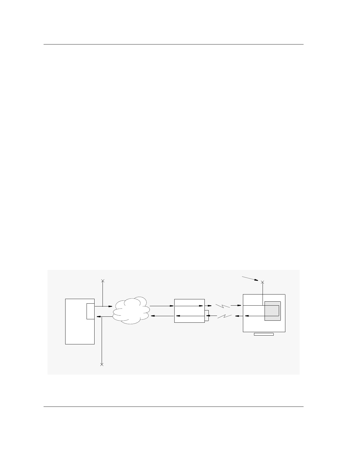
Performing tests using the DCSM in the directed mode 9-15
Wireless Solutions DualMode 800 Enclosure Maintenance Manual MTX08
TEST MRLP
This is the MTX RF Transmitter test. The test measures the following:
• the Tx Power(dBm) of the Forward RF link
The MRLP test can be invoked in the following ways:
• from a posted transceiver at the VCH MAP level
• from the CTT level (all available VCH are tested starting with the first
available)
• automatically using Table CTTSCHED (this also selects the first available
VCH)
Once the test is invoked a call is terminated to the DCSM mobile. The DCSM
then transmits a 1004 Hz tone at 2.9 kHz deviation for five seconds, after
which the FWD audio is looped to the REV audio. The TTT then transmits a
tone (level and frequency determined in Table CTTPARMS) which is
transmitted on the forward RF path by the DUT to the DCSM. The DCSM
subsequently loops the forward audio to the reverse audio and transmits the
tone to the DUT through the reverse RF path. Once the link has been verified,
the DCSM is instructed by the MTX to measure the level of the forward RF
signal. The measured level is returned to the MTX by the DCSM for
reporting. Refer to Figure 9-7 for a diagram of the test operation.
The test either passes or fails depending on the level returned is within the
limits set by the MRLP tuple in Table CTTPARMS. Table CTTGROUP
defines the RF power level which the DCSM should measure.
Figure 9-7
MRLP Test Measurements
DCSM
DUT
TTT
NM Network
DRU or BST
MS
RF path
The TTT measures
the tone level
RSSI Measured
The DCSM measures
the RSSI of the Near-
to-far on-air link.
Tone transmitted

9-16 Performing tests using a DCSM
411-2051-500 Draft 00.01 November 1999
How to invoke the MRLP test
Before the test is run the appropriate CTTPARMS tuple must be datafilled
with the correct criteria. With the CTTPARMS tuple correctly datafilled and
selected through CTTGROUP, the test may be initiated either manually from
the MAP level (VCH or CTT) or automatically using CTTSCHED. Procedure
9-9 outlines the manual method of invoking the MRLP test.
Figure 9-8
MRLP Test results MTX302 Log
Refer to the DualMode 800 Enclosure Troubleshooting Guide, 411-2051-900,
for more information of the fields in MTX303 Log. Below are the descriptions
of the fields of MTX302 which give the actual measure results:
Tx PWR - The measured forward RF power in dBm
Troubleshooting action
If the test fails then it should be repeated for verification. Should the test still
fail the following hardware components may be at fault:
• TRU (ACH & VCH)
• Power Amplifier
Procedure 9-10
Initiating the MRLP test
Step Action Observation
1 Go to the MAP level of the MTX radio (VCH) to be
tested:
(example) MAPCI;MTC;MTX;CELL 100;VCH
2 Post the radio to be tested:
(example) POST 2
3 Invoke the MRLP test on the posted radio:
TST MRLP
The MTX will respond
that the test is underway.
4 Wait for the results of the MRLP test. The MTX
will display them once the test is complete. See Figure 9-8.
5 If the results fails check to see if the CTTPARMS
fields are correctly set. Then repeat the test to
verify the failure.
MTX302 JUN29 12:12:12 2500 CTT RF POWER TEST
CELL: 20x TEST: MRLP VCH: 10 HW: BST
VPL : 0 Tx PWR: -50 dBm EXP PWR: -58 dBm
Q1PWR: 0 dB Q2PWR: 2 dB
PASS

Performing tests using the DCSM in the directed mode 9-17
Wireless Solutions DualMode 800 Enclosure Maintenance Manual MTX08
• Combiner
• ICRM packs (the AX50s, AX47s, AX87s)
• T1 transmission equipment used
• ICP cards (the AX50s, AX27s)
•DCSM
The signal may be rerouted to eliminate and pinpoint faulty hardware
components, or the equipment may be swapped one at a time with known
good units and the test repeated. When the test passes the faulty unit may have
been found. Additionally, determine if the MALT or MAHT test has passed or
not to isolate the path failure location further.
TEST MRLR
The MTX Radio receiver test. The test measures the following:
• the RSSI (dBm) of the reverse RF path
• the Loop Loss in dB
Once the test is invoked a call is terminated to the DCSM mobile. The DCSM
then transmits a 1004 Hz tone at 2.9 kHz deviation for five seconds, after
which the FWD audio is looped to the REV audio. The TTT then transmits a
tone (level and frequency determined in Table CTTPARMS) which is
transmitted on the forward RF path by the DUT to the DCSM. The DCSM
subsequently loops the forward audio to the reverse audio and transmits the
tone to the DUT through the reverse RF path. Once the link has been verified,
the DUT is instructed by the MTX to measure the RSSI of the received RF
signal on the reverse RF path. The measured RSSI is returned to the MTX for
reporting along with the looped level measured by the TTT. Refer to Figure 9-
9 for a diagram of the test operation.
The test either passes or fails depending on the RSSI level returned is within
the limits set by the MRLR tuple in Table CTTPARMS. Table CTTGROUP
defines the RF power level which the DCSM should transmit on the reverse
path.
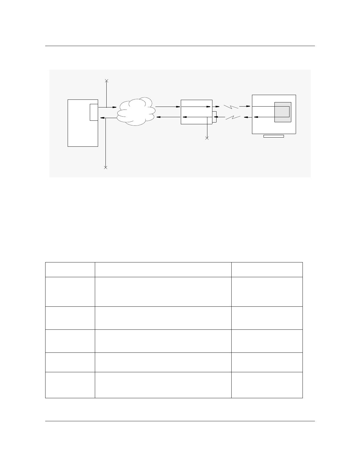
9-18 Performing tests using a DCSM
411-2051-500 Draft 00.01 November 1999
Figure 9-9
MRLR Test Measurements
How to invoke the MRLR test
Before the test is run, the appropriate CTTPARMS tuple must be datafilled
with the correct criteria. With the CTTPARMS tuple correctly datafilled and
selected through CTTGROUP, the test may be initiated either manually from
the MAP level (VCH or CTT) or automatically using CTTSCHED. Procedure
9-11 outlines the manual method of invoking the MRLR test.
Procedure 9-11
Initiating the MRLR test
Step Action Observation
1 Go to the MAP level of the MTX radio (VCH) to be
tested:
(example) MAPCI;MTC;MTX;CELL 100;VCH
2 Post the radio to be tested:
(example) POST 2
3 Invoke the MRLR test on the posted radio:
TST MRLR
The MTX will respond
that the test is underway.
4 Wait for the results of the MRLR test. The MTX
will display them once the test is complete. See Figure 9-10.
5 If the results fails check to see if the CTTPARMS
fields are correctly set. Then repeat the test to
verify the failure.
DCSM
DUT
TTT
NM Network
DRU or BST
MS
RF path
The TTT measures
the tone level
The DUT measures
the RSSI of the Far-
to-near on-air link.
RSSI measured
Tone transmitted

Performing tests using the DCSM in the directed mode 9-19
Wireless Solutions DualMode 800 Enclosure Maintenance Manual MTX08
Figure 9-10
MRLR Test results MTX302 Log
Refer to the DualMode 800 Enclosure Troubleshooting Guide, 411-2051-900,
for more information of the fields in MTX303 Log. Below are the descriptions
of the fields of MTX302 which give the actual measure results:
Tx PWR - The measured reverse RF level in dBm
Troubleshooting action
If the test fails then it should be repeated for verification. Should the test still
fail the following hardware components may be at fault:
• the TRU (ACH & VCH)
• ICRM packs (the AX50s, AX47s, AX87s)
• the T1 transmission equipment used
• the ICP cards (the AX50s)
• the DCSM
The signal may be rerouted to eliminate and pinpoint faulty hardware
components, or the equipment may be swapped one at a time with known
good units and the test repeated. When the test passes the faulty unit may have
been found.
MTX Call Processing Mobile Termination Test (MTRM or DTRM)
For this test the DCSM is used to terminate a call. This test provides
verification of all call set-up commands and messages between the cell site
CCH, the AVCH under test and the ICP. Call set-up is through the ACCH
(MTRM) or DCCH (DTRM) to an AVCH.
For this test, use:
•MTRM if the partitions ACCH is to set-up the call termination test or
•DTRM if the partitions DCCH is to set-up the call termination test
The mobile termination test is invoked from the VCH level of the MAP
position (test DTRM or MTRM). The posted VCH must be an AVCH. If the
posted VCH is a DTCH or DualMode VCH, the call will be in digital mode.
The user will be notified if an attempt is made to run the MTRM or DTRM
test on an AVCH which is servicing a call.
MTX302 JUN29 12:12:12 2500 CTT RF POWER TEST
CELL: 20x TEST: MRLR VCH: 10 HW: BST
VPL : 0 Tx PWR: -50 dBm EXP PWR: -58 dBm
Q1PWR: 0 dB Q2PWR: 2 dB
PASS

9-20 Performing tests using a DCSM
411-2051-500 Draft 00.01 November 1999
Invoking the DTRM test
Now that the DCSM (scanning the DCCH of the partition) and the VCH are
posted the Call Termination test may be performed:
Procedure 9-12
Invoking the DTRM or MTRM tests
Step Action Observation
1 At the VCH MAP level enter:
TST DTRM or TST MTRM
The MAP terminal will respond with an MTX301 Log
displaying the results of the DCCH or ACCH call setup.

10-1
Wireless Solutions DualMode 800 Enclosure Maintenance Manual MTX08
ICRM tests 10
There are no operational tests for the Integrated Cellular Remote Module
(ICRM) at the cell site. If you want to check the operation of the ICRM,
contact the operator at the MTX for assistance.

10-2 ICRM tests
411-2051-500 Draft 00.01 November 1999

11-1
Wireless Solutions DualMode 800 Enclosure Maintenance Manual MTX08
DRU tests 11
Introduction
The DualMode Radio Unit (DRU) is a cell site transceiver and power
amplifier combination that operates in either a TDMA (digital) mode or in a
conventional AMPS (analog) mode. For a DualMode 800 Enclosure, the DRU
is packaged in two sub-modules, the Transmit Receive Unit (TRU) and the
Multi-Channel Power Amplifier (MCPA) module.
TRUs are datafilled as analog only, digital only, or dual-mode from the
Maintenance and Administration Position (MAP) terminal which is typically
located at the Digital Multiplex System-Mobile Telephone Exchange (DMS-
MTX). When datafilled as dual-mode, TRUs operate dynamically in either
AMPS or TDMA mode, based upon control from the switch. Whether
operating in AMPS or TDMA mode, the TRU uses the same internal DSP-
based circuitry to process both voice and data.
The use of Digital Signal Processing (DSP) technology greatly reduces
maintenance requirements. Due to functions being performed by software
code, rather than circuits composed of discrete elements that cause drift over
time and with temperature change, radio performance levels are improved and
routine maintenance schedules can be eliminated.
The DSP architecture of the TRU and microprocessor control of the MCPA
allow for very stable performance and consistency from one unit to another.
No manual adjustments are required on the TRU or the MCPA. There are, in
fact, no manual adjustable components in the TRU or MCPA. All adjustments
to operational parameters are made through the TRU terminal interface.
The most important item governing correct DRU operation is a proper, non-
corrupt, software load within the TRU. The TRU software load is
downloadable from the MAP position through a Peripheral Module (PM) load
tape. TRUs can be upgraded or reloaded with their operating software without
requiring anyone to visit a cell site.
Figure 11-1 and Figure 11-2 show the front panel layouts of the TRU2 and the
TRU3 respectively. Figure 11-3 shows the front panel layout of the MCPA.
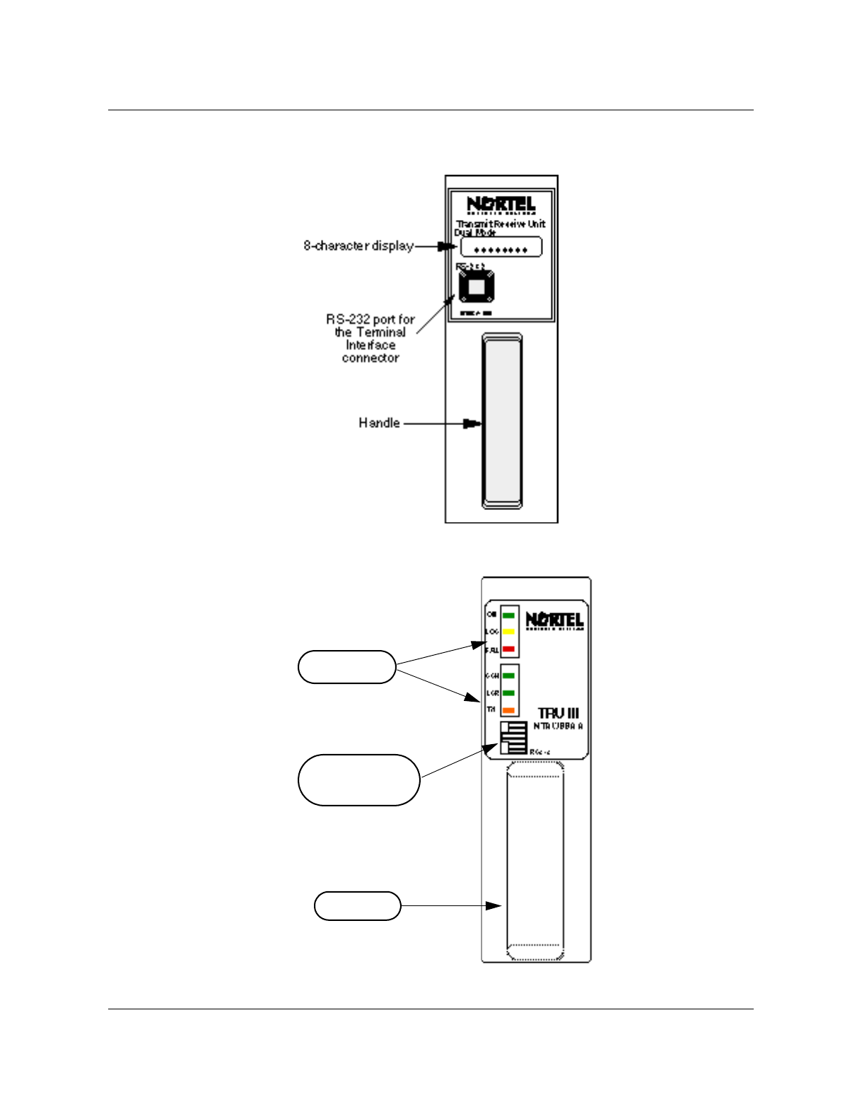
11-2 DRU tests
411-2051-500 Draft 00.01 November 1999
Figure 11-1
Front panel layout of the TRU2 (NTAX98AA)
Figure 11-2
Front panel layout of the TRU3 (NTAW99AA)
RS-232 port for the
Terminal Interface
connector
Handle
Status LEDs
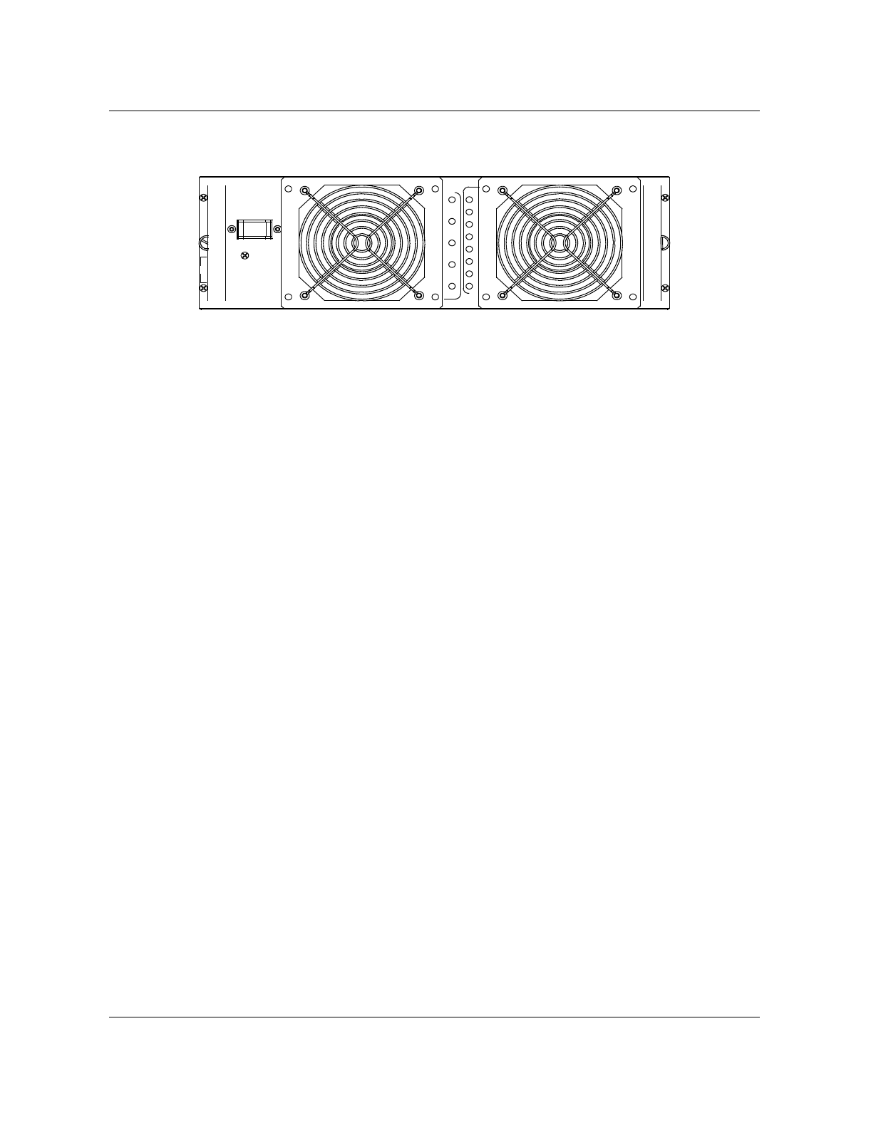
Functionality of the DRU 11-3
Wireless Solutions DualMode 800 Enclosure Maintenance Manual MTX08
Figure 11-3
MCPA front panel layout
Functionality of the DRU
The TRU provides a Time Compressed Multiplex (TCM) interface with the
Integrated Cellular Remote Module (ICRM). It also provides dual-receive
paths and diversity switching, and controls the Operation, Administration,
and Maintenance (OA&M) functions for the DRU. Control and signaling
messages communicated between the ICRM and the TRU are through a TCM
D-channel. Voice and data signals are communicated between the ICRM and
the TRU through a TCM B-channel.
Depending on the mode, the AMPS or TDMA baseband signal generated by
the TRU in a DualMode 800 Enclosure is modulated in the TRU. The
modulated signal is then sent to the MCPA. The MCPA amplifies and
transmits the signal to the mobile in the appropriate AMPS (analog) or π/4
DQPSK (digital) format. The TRU receives composite RF signals from the
mobile, extracts embedded control messages, and routes the control and voice
signals to the ICRM.
Audio sensitivity of the TRU
In AMPS mode, as a speaker talks, the FM carrier varies as a function of the
audio waveform produced by the speaker’s voice. This variance is known as
the frequency deviation that corresponds to a specific audio level. Typical
audio levels range anywhere from -18 dBm0 to -22 dBm0.
For TDMA, the speech signal is encoded using the VSELP coding algorithm.
The VSELP codec per the IS-54-B standard is optimized for a value being
equated to an audio level of -18 dBm0. Therefore, if an AMPS radio is not set
to an audio sensitivity of -18 dBm0, there will be some noticeable contrast in
audio level (loudness) when handoff occurs between the two modes.
To minimize the contrast between the two modes, Nortel Networks
recommends that the audio level in an analog network be adjusted to -18
dBm0, corresponding to ±2.9 kHz deviation, in each direction of
transmission. This recommendation concurs with the Joint Experts Meeting
as reported to the CTIA in March 1992. For TRUs working in the AMPS
OFFON
Pwr
Low
DISAB.
Alarms
Off
On
RF ON
-5VDC
Reset
Pwr
LPA
+5VDC Loop
Fail
Fail
Fan
Fail
+15VDC
+27VDC
VSWR
DC
High
Temp
Over
Status

11-4 DRU tests
411-2051-500 Draft 00.01 November 1999
mode to be fully IS-54-B compliant, the audio sensitivity is factory set to -18
dBm0. However, the audio sensitivity can be adjusted by performing the
Transmit and the Receive Audio Level tests as described later in this chapter.
Test considerations
This manual outlines the tests that should be performed on a DualMode Radio
Unit (DRU) when it is installed or replaced. It describes tests that can be
performed on the DRU, although not required, in a DualMode 800 Enclosure.
Also described are system checks related to a complete cell site system
containing DRUs. The tests ensure that the DRU provides service to mobile
users and meets the basic operating parameters. The tests are divided into the
following sections in this manual:
• Installation/Replacement tests—check the operational parameters of the
DRU
• Transmit tests—check the transmit parameters of the DRU
• Receive tests—check the receive parameters of the TRU
• Power output test—checks the transmit power level of the MCPA at the
duplexer
• Digital tests— the bit error rate loopback test checks that the transmit and
receive paths of the TRU meet the specifications. A digital call through
test checks that TDMA call processing is performed correctly.
Note: The tests apply to both the TRU2 and TRU3 unless otherwise
stated for the individual unit. Currently the TRU3 does not support AMPS
operation and therefore performing the AMPS-related tests (for example,
SAT/ST frequencies, TX/RX audio levels) are not required on the TRU3.
Due to the operating characteristics of the DRU being determined by
software, very few tests are needed upon installation of a TRU or a MCPA
into a TRU shelf or a MCPA shelf respectively.
Tests that can be performed on a DRU as operational checks are outlined in
this chapter. These tests are not required upon installation, replacement, or on
a periodic basis, but are outlined for troubleshooting purposes.
Due to the tests affecting the ability to process calls, it is necessary to “busy
out” and “off-line” the DRUs, from the MTX, before testing begins.
CAUTION
Some of the tests are service affecting at the cell/sector level. If
you do need to perform these tests, schedule your work at a
low traffic period to minimize service interruption to your
customers.

Test equipment required 11-5
Wireless Solutions DualMode 800 Enclosure Maintenance Manual MTX08
Whenever a test is performed on a DRU, record the test parameter. You
should test only one DRU at a time. Unless specified elsewhere, testing
should be carried out within the +15° C (+59° F) to +35° C (+95° F)
temperature range.
Power and Ground Verification (Chapter 4), Master Oscillator Testing and
(Chapter 5) may be required before conducting some DRU tests.
Test equipment required
Proper setup of the test equipment is critical in obtaining proper test results.
Consistency of setup and techniques from one person to another is essential
for obtaining proper system operation.
It is assumed that the operator is familiar with the test equipment used in the
test procedures. The following test equipment is recommended for
performing the tests. Any functionally equivalent unit may be used in its
place. Double shielded coaxial cables are recommended for use between test
equipment and the cell site equipment being tested.
Note: Ensure that all test equipment is calibrated before use. Cable loss
must be accounted for in the MCPA RF output power tests.
For a list of the required test equipment, refer to Chapter 3, Test Equipment
and Precautions, in this manual.
This section describes the tests that can be performed on a DualMode Radio
Unit (DRU). These tests can be used to verify the performance of a DRU but
they are not required on a periodic basis.
Note: The DRU, the ICRM and the test equipment should be powered up
for at least half an hour before the tests. Inaccurate measurements may
result if the warm-up period is less than 30 minutes.
A VT100 Video Display Terminal (or equivalent) is required to perform the
tests. Refer to the Test Equipment section in Chapter 3, Test Equipment and
Precautions, for setting up the parameters of the terminal. For a complete list
of the Terminal Interface commands, refer to the Transmit Receive Unit
section in Chapter 1, Equipment operation.
TRU self test
A built-in self test can be performed on a TRU (EEPROM CRC check for a
TRU2 and a CRC check for a TRU3).
Use the following procedure to perform the self test:
1. Connect the interface terminal to the RS-232 port on the front panel of the
TRU under test.

11-6 DRU tests
411-2051-500 Draft 00.01 November 1999
2. Place the TRU into the command line mode by pressing the “Break” key
on the interface terminal. The terminal will display the following:
TRU Terminal Interface
Copyright 1990,1991 Bell Northern Research, Inc.
>
3. To place the TRU into the fullscreen monitor mode, enter:
>SET LT OFF (disables the LAPD timeout)
>SET FS ON (invokes fullscreen display)
This places the TRU into the fullscreen AMPS mode (refer to Figure 1-8).
TRU EEPROM CRC Check
4. Check the top right corner of the screen and verify that the EEPROM
CRC Check has passed. The EEPROM CRC Check on the screen (refer to
Figure 1-8 in Chapter 1, Equipment operation) will show:
EEPROM CRC Check: PASSED
Record the result. If the check fails, replace the TRU.
5. Disconnect the interface terminal from the TRU under test.
DRU configurations for analog tests
The Transmit Receive Unit (TRU) must be correctly configured for each test.
This section covers the general test set-ups for the TRU.
Nominal Application Gain
In a DualMode 800 Enclosure, all TRUs are set to “patype none” mode
during installation. In this mode, the nominal application gain is set to a
default value of -12 dB and the TRU maximum transmit power is set to a
default value of +15 dBm. Do not change these default settings during the
tests.
With default settings in the “patype none” mode, the output of the TRU is set
to [+15 - (-12)] = +27 dBm at the TRU backplane. Therefore, when checking
the TRU output with the “query pastatus” command, please remember that
the +15 dBm TRU output has been compansated for by the -12 dB norminal
application gain to give an actual TRU output of +27 dBm at default.

DRU configurations for analog tests 11-7
Wireless Solutions DualMode 800 Enclosure Maintenance Manual MTX08
TRU setup
All the DualMode Radio Unit (DRU) tests are performed through an interface
terminal. Before performing any tests, connect an interface terminal to the RS-
232 port on the front panel of the TRU. Place the TRU into the command line
mode by pressing the “Break” key on the terminal. To place the TRU into the
fullscreen analog (AMPS) mode, at the command line prompt (>), enter:
>SET LT OFF (disables the LAPD timeout)
>SET PATYPE NONE (configures TRU to the modulated mode for no per-
carrier PA application)
>SET FS ON (invokes fullscreen display)
Check the configurations of the TRU from the interface terminal. For each
individual test, change the specific configuration(s) as required. Table 11-1
shows the TRU configurations in the initial setup and in the individual tests.
Status or values in bold indicate the change to that specific configuration
during the tests. Refer to Table 1-2 in Chapter 1, Equipment operation, for a
complete description of the fullscreen commands.
With reference to Table 11-1, verify that the DRU configurations are as listed
in the initial setups from the interface terminal:
Carrier status
If the carrier (shown in the PA field on the screen) is on, turn it off by
entering:
>C
The PA field on the screen should show:
PA: off
Compandor
If the Compandor is off, turn it on by entering:
>K
The Compandor field on the screen should show:
Compandor: on
SAT Transmit
If the SAT TX is on, turn it off by entering:
>G
The SAT TX field on the screen should show:
SAT TX: 6000 (off)

11-8 DRU tests
411-2051-500 Draft 00.01 November 1999
Table 11-1
DRU configurations for analog tests
Commands G I J K L P N M E U F C R T
TX Tests Initial Setup
TRU Configurations Receive Status TRU Power Settings TX/RX Audio
Audio
Status Audio
Sens
Max
Power Carrier
On/Off
Power
Index Power
Step
Antenna
Path Receive
Ports
Wide
Band
Data
Detect
SAT, ST,
RSSI
Loop
back Compan-
dor
SAT
TX Tone
Gen
OFF
OFF
OFF
ON
OFF
OFF
OFF
OFF
OFF
OFF
OFF
OFF
OFF
OFF
OFF
OFF
OFF
OFFOFF
OFF
OFF
OFF
OFF
OFF
OFF
OFF
OFF
OFF
RF
OFF
OFF
OFF
OFF
OFF
OFF
OFF
OFF
OFF
OFF
OFF
OFF
OFF
OFF
OFF
OFF
OFF
OFF
OFF
OFF
OFF
OFF
RF
RF
OFF
OFF
OFF
OFF
OFF
OFF
OFF
ON
ON
ON
ON
ON
ON
ON
ON
ON
ON
ON
ON
ON
ON
ON
ON
ON
ON
ON
ON
OFF
OFF
OFF
ON
OFF
OFF
OFF
OFF
OFF
OFF
OFF
OFF
OFF
OFF
OFF
OFF
OFF
OFF
OFF
OFF
OFF
OFF
OFF
OFF
OFF
OFF
OFF
OFF
OFF
OFF
OFF
OFF
OFF
OFF
RSSI
SAT
ST
OFF
OFF
OFF
A
A
A
A
A
A
A
A
A
A
A
A
A
A
A
A
A
A
A
A
1 4
1 4
1 4
1 4
1 4
1 4
1 4
1 4
1 4
1 4
1 4
1 4
1 4
1 4
1 4
1 4
1 4
1 4
1 4
1 4
0
0
0
0
0
0
0
0
0
0
0
0
0
0
0
0
0
0
0
0
4
4
4
4
4
4
4
4
4
4
4
4
4
4
4
4
4
4
4
4
15.0
15.0
15.0
15.0
15.0
15.0
15.0
15.0
15.0
15.0
15.0
15.0
15.0
15.0
15.0
15.0
15.0
15.0
15.0
15.0
OFF
OFF
ON
ON
ON
ON
ON
ON
ON
OFF
OFF
ON
ON
OFF
OFF
OFF
OFF
OFF
ON
OFF
OFF
OFF
OFF
OFF
OFF
OFF
TX
TX
OFF
OFF
OFF
OFF
TX RX
TX RX
RX
OFF
OFF
OFF
OFF
OFF
-18.0
-18.0
-18.0
-18.0
-18.0
-18.0
-18.0
-18.0
-18.0
-18.0
-18.0
-18.0
-18.0
-18.0
-18.0
-18.0
-18.0
-18.0
-18.0
-18.0
TX Carrier Frequency
Wideband Modulation
SAT Transmit
Residual Modulation
TX Audio Level
Modulation Limiting
1 kHz Tone Gen
End of TX Tests
RX Tests Initial Setup
Receive Sensitivity
RX/TX Audio Sens
RX Audio Level
RSSI Detect
SAT Detect
ST Detect
End of RX Tests
Power Test Initial Setup
TRU Power Output
End of Power Test

DRU configurations for analog tests 11-9
Wireless Solutions DualMode 800 Enclosure Maintenance Manual MTX08
Loopback
If the Loopback status is either BCH or RF, turn it off by entering:
>J
The TRU will request an antenna path choice (either BCH, RF or OFF). To
turn the Loopback off, enter:
>OFF
The Loopback field on the screen should show:
Loopback: off
Tone Gen
If the Tone Generation status is either BCH or RF, turn it off by entering:
>I
The TRU will request an antenna path choice (either BCH, RF or OFF). To
turn the Tone Gen off, enter:
>OFF
The Tone Gen field on the screen should show:
>Tone Gen: off
Antenna Path
If the Antenna Path status is not Path A, select Path A by entering:
>N
The TRU will request an antenna path choice (either A, B or DIV). To select
Path A, enter:
>A
The Antenna Path field on the screen should show:
>Antenna Path: A
Antenna Port
If the Antenna Port status is not Ports 1 and 4, select Ports 1 and 4 by
entering:
>M
The TRU will request the port numbers (enter a port number 1, 2 or 3 for
antenna path A, and a port number 4, 5 or 6 for antenna path B). Enter the
antenna ports as two numbers separated by a space (first number indicates
antenna port in path A and second number indicates antenna port in path B):
>1 4
The Antenna Port field on the screen should show:
>Antenna Port A: 1 B: 4

11-10 DRU tests
411-2051-500 Draft 00.01 November 1999
Transmit Power Level Index
If the TxPwrIndex status is not 0, set it to 0 by entering:
>E
The TRU will request a specific power level (0..7). To set power level to 0,
enter:
>0
The TxPwrIndex field on the screen should show:
TxPwrIndex: 0
Transmit Power Step Size
If the TxPwrStep status is not 4, set it to 4 by entering:
>U
The TRU will request a power step size (1..4 in 0.25 dB increments). To set
power step size to 4, enter:
>4
The TxPwrStep field on the screen should show:
TxPwrStep: 4
Maximum Transmit Power
If the PA Max power status is not 15.0 dBm, set it to 15.0 dBm by entering:
>F
The TRU will request a power level (-1.0...27.0 in dBm). To set Max power to
15.0, enter:
>15.0
The MaxTxPwr field on the screen should show:
MaxTxPwr: 15.00
Audio Status
If the TX and RX audio status is either ‘TX’, ‘RX’ or ‘TX RX’, turn the
audio off by entering:
>R
The DRU will request for either ‘TX’, ‘RX’, ‘BOTH’ or ‘OFF’. Enter:
>OFF
The Audio field on the screen should show:
Audio: off

DRU configurations for analog tests 11-11
Wireless Solutions DualMode 800 Enclosure Maintenance Manual MTX08
TX Audio Sensitivity
If the TX Audio Sens status is not -18.0, and no other level has been specified,
set the TX audio sensitivity to -18.0 dBm by entering:
>T
The DRU will respond as follows:
Enter TX or RX and a decimal dBm value (TX:-28...
-10);(RX:-28...-16)
Enter:
>TX -18.0
The Audio Sens TX status on the screen will show:
Audio Sens Tx: -18.0
RX Audio Sensitivity
If the RX Audio Sens status is not -18.0, and no other level has been
specified, set the RX audio sensitivity to -18.0 dBm by entering:
>T
The DRU will respond as follows:
Enter TX or RX and a decimal dBm value (TX:-28...
-10);(RX:-28...-16)
Enter:
>RX -18.0
The Audio Sens RX status on the screen will show:
Audio Sens Rx: -18.0
11-12 DRU tests
411-2051-500 Draft 00.01 November 1999
DRU transmit tests
This section describes the transmit tests that can be performed on the
DualMode Radio Unit (DRU). RF output power tests are described in the
DRU RF output power test section.
Note: The tests can be performed separately but the DRU transmit test
setup procedure must be performed before each individual test.
Service impacts
Directly testing the TRU through the antenna port of the duplexer will put the
entire cell/sector out of service.
Indirectly testing the TRU through the sniffer port of the duplexer will affect
only the TRU under test. However, the measurement may not be as accurate
because the level is approximately 50 dB down with a tolerance of up to ±5
dB.
Transmit test setup procedure
1. At the MTX, busy and off-line the TRU under test and the TRUs
connected to the same MCPA shelf.
Note: The service supported by the MCPA shelf will be affected.
2. Connect the interface terminal to the RS-232 port on the front panel of the
TRU under test. Verify that the DRU configurations for TX tests initial
setup are as listed in Table 11-1.
Note: Ensure that all the TRUs connected to the MCPA shelf are off.
WARNING
RF radiation hazard
Do NOT disconnect any RF cables when transmitters are on.
CAUTION
Service interruption
The service of the entire cell/sector of the TRU under test will
be affected. Perform the tests during low traffic period.

DRU transmit tests 11-13
Wireless Solutions DualMode 800 Enclosure Maintenance Manual MTX08
3. Connect the receive input of the communications monitor to the antenna
port of the duplexer. Use a low loss double shielded cable, RG-214 or
equivalent. Figure 11-4 shows the connection setup for the transmit tests.
Note: If you do not want to interrupt service, connect to the sniffer port
on the duplexer instead. The level is approximately 50 dB down with a
tolerance of up to ±5 dB.
4. From the terminal, select the channel assigned to the TRU under test by
using the B command.
>B
The TRU will request a channel number. Enter the channel number for the
frequency assigned to the TRU under test (1...799 or 990...1023). Refer to
Appendix A for the channel-to-frequency conversion information.
>xxxx
On a successful channel change, the Channel and Synth Lock fields will
be updated:
Channel: xxxx (DRU channel number indicated)
Synth Lock: YES (Sync Lock changes to ‘YES’)
5. On the communications monitor, set the transmit RF frequency to the
frequency corresponding to that of the TRU under test.
6. Turn on the TRU (the transmit carrier) with the C command.
>C
The PA status on the screen will change to:
PA: on
7. Proceed with the transmit tests.
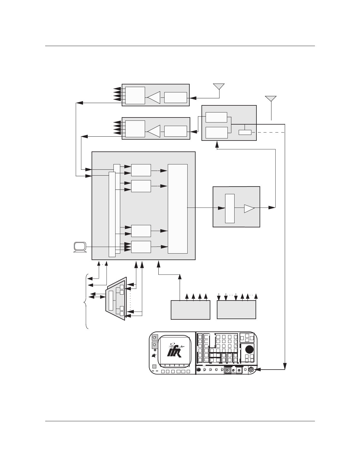
11-14 DRU tests
411-2051-500 Draft 00.01 November 1999
Figure 11-4
DRU transmit tests setup (service affecting)
Diversity Receive
Main
Transmit / Receive
TRU Shelf
Other TRU
Shelves
Other TRU
Shelves LNA Preselect
Filter
Receive Multicoupler
1:8 Splitters
1:8
Splitter
LNA
Duplexer
RX Bandpass
Filter
TX Bandpass
Filter
TRU 8
TRU 2
TRU 7
TRU 1
1:8
Splitter Preselect
Filter
Receive Multicoupler
Integrated
Cellular
Remote
Module
(ICRM)
Data
L
I
N
K
P
P
P
To
MTX
Voice
P
Alarm
Inputs Outputs
Other TRU
Shelves
Alarm
Control Unit
High Stability
MasterOscillator
Data
•••• • •
•••• • •
Communications Monitor (IFR 1600)
INTENSIT
Y
POWER
DUPLEX
OUT
ON
F1 F2 F3 F4 F6F5
MODE
ANTENNA
FM /AM 1600S
AUX
IN
FM/AM
1600S
65W
MAX
65W
MAX
APPLIED
RF
RCVR
DPLX
AF
SCOPE
MTRS
AUTO
SGL
GO
STOP
PRINT
HOLD
SETUP
STORE
0
CE
DEL
8
5
2
SHIFT
RCL
7
4
1
#
^
v
9
6
3
Enter
^
v
+
-
Mu
km
.
TESTCONTROL
DATAENTRY
MEMORY EDIT SQLCH VOL
FIELD SELECT
^
v
< >
^v
< >
MIC/ACC SINAD AUDIO DEMOD VΩCOM AMP SCOPE T/R
IN/OUT IN IN OUT OUT 1KVDC/500V
AC MAX 2 AMPS
MAX
IN
200 VDC
MAX
200W
MAX
IN/OUT
BER
DMM
DATASCROLL
EXT MOD
STEP
SCRN
SCRN
GEN
GEN
ANLZ
Sniffer
VT100
Tx
Combiner MCPAs
4:1 Combiner
MCPA Shelf

DRU transmit tests 11-15
Wireless Solutions DualMode 800 Enclosure Maintenance Manual MTX08
Transmit Carrier Frequency test
This test ensures that the TRU is transmitting at the assigned frequency.
Wideband Modulation test
This test ensures that the transmit carrier deviation of the TRU is within
specifications when the TRU is transmitting wideband data.
Step Action Observation
1 Ensure that the TRU configurations are as
listed in Table 11-1 for the Transmit Carrier
Frequency test.
2 Check the transmit carrier frequency on the
communications monitor. The frequency
error (FREQ ERR) is also shown on some
communications monitors.
±220 Hz of the assigned frequency.
3 Record the assigned frequency (in MHz) and
the frequency error (in Hz) on the test forms.
Step Action Observation
1 Ensure that the TRU configurations are as
listed in Table 11-1 for the Wideband
Modulation test.
2 From the interface terminal, use the L
command to select Wideband Data.
>L
TRU begins to transmit wide band data and
the screen shows:
continuing Wideband Data TX..
(press return to quit)
3 Check the carrier frequency deviation as
displayed on DEV (deviation) meter. Deviation between 7.2 kHz and 8.8 kHz.
4 Record the deviation on the test forms.
5 Press the “Return” key to stop the wideband
data transmission. TRU stops transmitting wide band data and
the screen shows:
Wideband data is off

11-16 DRU tests
411-2051-500 Draft 00.01 November 1999
SAT Frequency and Deviation tests
Supervisory Audio Tones (SAT) are used for out-of-band signaling. This test
ensures that the SAT frequency and deviation transmitted by the TRU are
within specifications.
Step Action Observation
1 Ensure that the TRU configurations are as
listed in Table 11-1 for the SAT Transmit test.
2 From the interface terminal, use the G
command to turn on the SAT.
>G
The screen shows:
SAT TX: 6000 (on)
3 Check the SAT frequency as displayed on
the AF (frequency) meter. SAT frequency should be 6000 Hz ±5 Hz.
4 Check the SAT carrier frequency deviation as
displayed on the deviation (DEV) meter. Deviation between 1.8 kHz and 2.2 kHz.
5 Record the frequency and the deviation on
the test forms.
6 Use the H command to input a different SAT
frequency.
>H
The terminal will prompt with:
Enter a SAT frequency (5970,
6000, or 6030)
7 Select 5970 Hz SAT frequency by entering:
>5970
The screen shows:
SAT TX: 5970 (on)
8 Repeat steps 3 to 5 for the 5970 Hz SAT
frequency and deviation tests. SAT frequency: 5970 Hz ±5 Hz
Deviation between 1.8 kHz and 2.2 kHz.
9 Repeat steps 6 to 8 for the 6030 Hz SAT
frequency and deviation tests by selecting
6030 Hz SAT frequency.
SAT frequency: 6030 Hz ±5 Hz
Deviation between 1.8 kHz and 2.2 kHz.
10 Use the G command to turn off the SAT.
>G
The screen shows:
SAT TX: 6030 (off)

DRU transmit tests 11-17
Wireless Solutions DualMode 800 Enclosure Maintenance Manual MTX08
Residual Modulation test
This test ensures that the transmit carrier deviation of the TRU is within
specifications when the transmit audio of the TRU is muted.
Transmit Audio Level test
This test ensures that the transmit carrier deviation of the TRU meets the
audio level specifications during a subscriber conversation in the AMPS
mode.
The AMPS mode of the TRU is currently set to a default value of -18 dBm0,
corresponding to ±2.9 kHz deviation, which is compliant to IS-138 Standards.
Step Action Observation
1 Ensure that the TRU configurations are as
listed in Table 11-1 for the Residual
Modulation test.
2 Check the carrier frequency deviation as
displayed on the DEV meter. Deviation between -0.5 kHz and +0.5 kHz.
3 Record the deviation on the test forms.
Step Action Observation
1 Ensure that the TRU configurations are as
listed in Table 11-1 for the Transmit Audio
Level test.
Note:
Loopback and SAT TX must be set to
off in this test. Use the J and the G
commands to set Loopback and SAT TX to
off, if necessary.
The desired trunk should still be posted as in
the Tx Audio Level Test step 4.
2 From the interface terminal, use the R
command to turn on (unmute) the TX audio.
>R
The terminal will prompt for audio path:
Enter TX, RX, BOTH or OFF
3 Enter the option “TX”:
>TX
The Audio status on the screen shows:
Audio: TX
- continued -

11-18 DRU tests
411-2051-500 Draft 00.01 November 1999
Modulation Limiting test
Modulation Limiting is the ability of the transmitter to effectively operate
within the system deviation limits. This test ensures that the transmit
carrier deviation of the TRU meets the system specifications.
4 This step is performed at the MTX.
From the MAP position or with a second
terminal logged into the switch, test the trunk
that is assigned to the TRU being tested by
entering:
MAPCI;MTC;TRKS;TTP;POST (CLLI name)
(Trunk member number);TGEN 1004 -180
MAP Trunk Test Position is displayed. The
MAP screen will indicate the trunk member
selected and that the trunk is selected.
It will also indicate the tone generated and
the level of the tone.
5 Check the carrier frequency deviation as
displayed on the DEV meter. Deviation between 2.61 kHz and 3.19 kHz.
6 Record the deviation on the test forms.
7 If the deviation is different from the site
specific Forward audio level setting, repeat
this test after all the transmit tests have been
completed. Set the deviation to the specific
operational level with the T command from
the interface terminal.
The transmit audio level is shown on the
terminal screen as:
Audio Sens Tx: -18.0 (change this
level as required—a change of 1 dBm is
approximately a change of 0.27 kHz in
deviation)
8 From the interface terminal, use the R
command to turn off (mute) the TX audio.
>R
The terminal will prompt for audio path:
Enter TX, RX, BOTH or OFF
9 Enter the option “OFF”:
>OFF
The audio status on the screen shows:
Audio: off
- End -
Step Action Observation

DRU transmit tests 11-19
Wireless Solutions DualMode 800 Enclosure Maintenance Manual MTX08
Step Action Observation
1 Ensure that the TRU configurations are as
listed in Table 11-1 for the Modulation
Limiting test.
Note:
Loopback and SAT TX must be set to
off in this test. Use the J and the G
commands to set Loopback and SAT TX to
off, if necessary.
2 From the interface terminal, use the R
command to turn on (unmute) the TX audio.
>R
The terminal will prompt for audio path:
Enter TX, RX, BOTH or OFF
3 Enter the option “TX”:
>TX
The Audio status on the screen shows:
Audio: TX
4 This step is performed at the MTX.
Using the TGEN command at the MAP
position terminal, change the output level
and observe the Carrier Frequency Deviation
for each of the levels listed.
TGEN 1004 -100..........
TGEN 1004 -50...........
TGEN 1004 0.............
TGEN 1004 10............
TGEN 1004 20............
TGEN 1004 30............
TGEN 1004 50............
The Carrier Frequency Deviation will
increase to a maximum value at a certain
tone level and then the deviation value will
decrease. However, the maximum value
must be less than 12.0 kHz at all tone levels.
5 Check the maximum carrier frequency
deviation as displayed on the DEV meter. Deviation must be less than 12.0 kHz at all
levels.
6 Record the maximum deviation obtained on
the test forms.
7 On the MAP position terminal, enter:
>RLS
The MAP screen will indicate that the trunk is
released and returns to its original state.
8 From the interface terminal, use the R
command to turn off (mute) the TX audio.
>R
The terminal will prompt for audio path:
Enter TX, RX, BOTH or OFF
9 Enter the option “OFF”:
>OFF
The Audio status on the screen shows:
Audio: off

11-20 DRU tests
411-2051-500 Draft 00.01 November 1999
1 kHz Tone Generation test
This test ensures that the frequency and deviation of the 1 kHz test tone
generated by the TRU are within specifications.
Step Action Observation
1 Ensure that the TRU configurations are as
listed in Table 11-1 for the 1 kHz Tone Gen
test.
2 From the interface terminal, use the I
command to generate an on-channel 1 kHz
tone at 8 kHz deviation.
>I
The TRU will prompt for the antenna path
choice:
Enter BCH, RF, or OFF
3 Enter the RF option to test the tone on the
RF side of the TRU.
>RF
The Tone Generation status on the screen
shows:
Tone Gen: RF
4 Check the 1 kHz Tone Gen frequency as
displayed on the AF meter. The frequency should be 1000 Hz ±1 Hz.
5 Check the carrier frequency deviation as
displayed on the DEV meter. Deviation between 7.2 kHz and 8.8 kHz.
6 Record the frequency and the deviation on
the test forms.
7 Use the I command to turn off the on-
channel 1 kHz tone at 8 kHz deviation.
>I
The TRU will prompt for the antenna path
choice:
Enter BCH, RF, or OFF
8 Enter the “OFF” option to turn off the tone on
the RF side of the TRU.
>OFF
The Tone Generation status on the screen
shows:
Tone Gen: OFF

DRU transmit tests 11-21
Wireless Solutions DualMode 800 Enclosure Maintenance Manual MTX08
Setting TX audio deviation to site operational level
After the transmit tests, ensure that the deviation level recorded in the
Transmit Audio Level test is the same as the site specific operational level. If
the levels are different, perform the Transmit Audio Level test and change the
level to the site specific operational level by using the T command.
Set the TX audio sensitivity with the T command.
>T
The TRU will prompt as follows:
Enter TX or RX and a decimal dBm value (TX:-28...
-10);(RX:-28...-16)
Enter:
>TX -xx.x (change this value as required to obtain the operational
transmit audio level)
Note: A change of 1 dBm is approximately a change of 0.27 kHz
deviation.
The Audio Sens TX status on the screen will show:
Audio Sens Tx: -xx.x (site specific operational level)
Use the C command to turn off the carrier of the TRU.
>C
The PA (TRU transmitter) status on the screen will show:
PA: off
Use the Y command to perform a reset on the TRU after the tests.
>Y
At the command prompt, perform a warm reset on the TRU by entering:
>W
The TRU will return to its normal working condition after the reset.
Disconnect the interface terminal from the TRU.
At the MTX, put the TRU back to service.

11-22 DRU tests
411-2051-500 Draft 00.01 November 1999
DRU receive tests
This section describes the receive tests that can be performed on the
DualMode Radio Unit (DRU).
Note: The tests can be performed separately but the DRU receive test
setup procedure must be performed before each individual test.
Service impacts
The receive tests cause a reduction in the receive performance of the shelf
containing the radio under test because of the loss of receive diversity.
The TRU transmit tests must be performed before the receive tests to verify
the TRU’s transmit path. This is because the TRU uses an RF loopback to
access the base-band receive signal. Failure to verify the TRU transmit path
may result in invalid test data.
Receive test setup procedure
1. At the MTX, busy and off-line the TRU under test.
2. Connect the interface terminal to the RS-232 port on the front panel of the
TRU under test. Verify that the TRU configurations for RX tests initial
setup are as listed in Table 11-1.
3. Connect the transmit output of the communications monitor to the
antenna input connector on the back of the TRU shelf for the antenna
under test. Connect the receive input of the communications monitor to
the sniffer port of the duplexer for the TRU under test. Use low loss
double shielded cables, RG-214 or equivalent. Figure 11-5 shows the
setup for the receive tests.
4. From the terminal, select the channel assigned to the DRU under test by
using the B command.
>B
WARNING
RF radiation hazard
Do NOT disconnect any RF cables when transmitters are on.
CAUTION
Service interruption
The service of the shelf housing the TRU under test will be
affected. Perform the tests during low traffic period.

DRU receive tests 11-23
Wireless Solutions DualMode 800 Enclosure Maintenance Manual MTX08
The DRU will request a channel number. Enter the channel number for the
frequency assigned to the DRU under test (1...799 or 990...1023). Refer to
Appendix A for the channel-to-frequency conversion information.
>xxxx
On a successful channel change, the Channel and Synth Lock fields will
be updated:
Channel: xxxx (DRU channel number indicated)
Synth Lock: YES (Sync Lock changes to ‘YES’)
5. On the communications monitor, set the receiver RF frequency to the
frequency corresponding to that of the DRU under test. For an IFR 1600,
by selecting the transmitter frequency, the receiver frequency will
automatically be set.
6. Proceed with the receive tests.
After performing a receive test on the A path of the receiver, perform the test
again on the B path. From the terminal, use the N command to change the
Antenna Path to ‘B’ and use the M command to select antenna port 4 for the
new receive path.
Note: Change the connection to the antenna input port 4 accordingly.
For sectored sites, perform also the following:
1. Use the N command to change the Antenna Path to ‘A’ and use the M
command to change the antenna ports to 2 and 5. Perform the receive
tests.
2. Use the N command to change the Antenna Path to ‘B’ and ensure that the
antenna ports are still 2 and 5. Perform the receive tests.
3. Use the N command to change the Antenna Path to ‘A’ and use the M
command to change the antenna ports to 3 and 6. Perform the receive
tests.
4. Use the N command to change the Antenna Path to ‘B’ and ensure that the
antenna ports are still 3 and 6. Perform the receive tests.
Note: Change the connection to the antenna input ports accordingly.
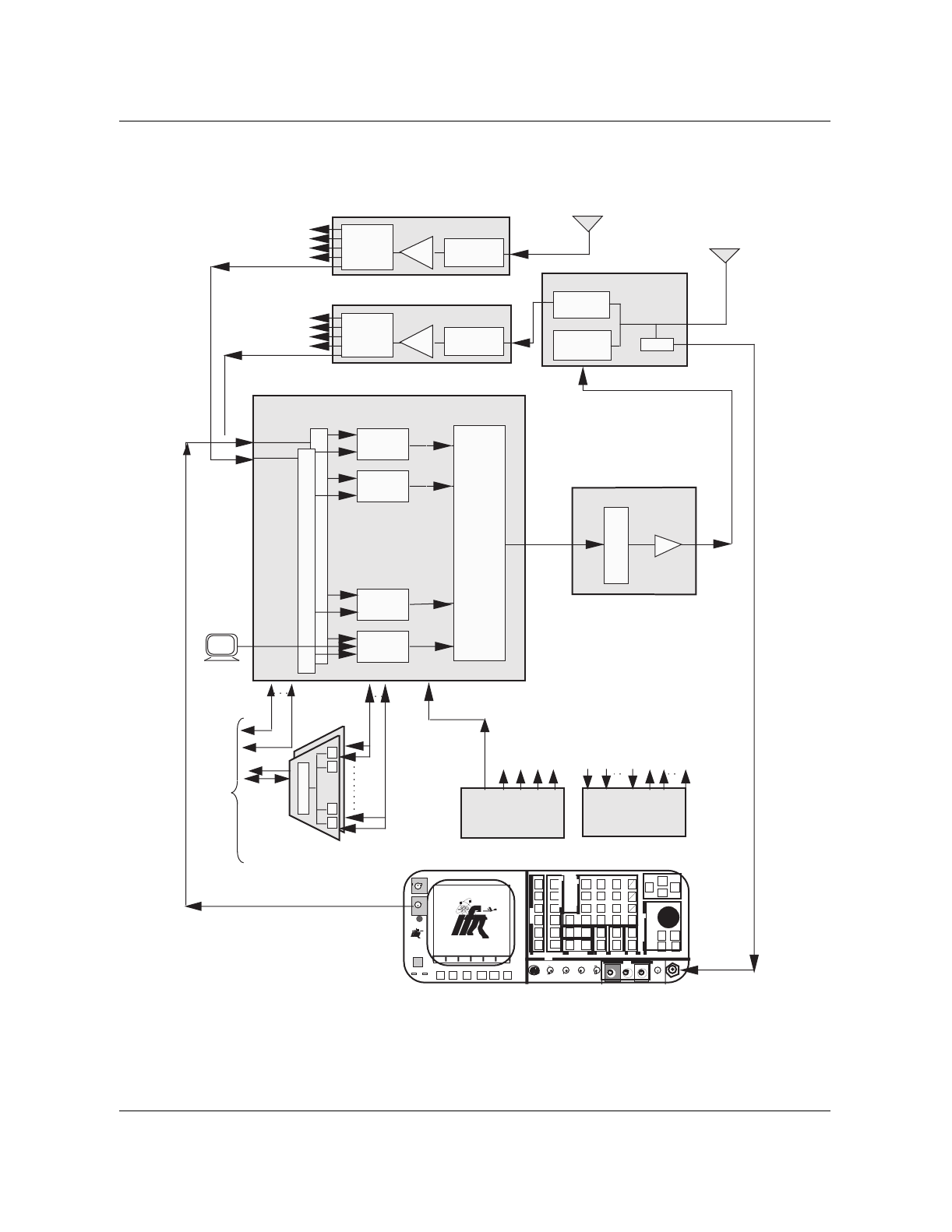
11-24 DRU tests
411-2051-500 Draft 00.01 November 1999
Figure 11-5
DRU receive tests setup (shelf/site service affecting)
Diversity Receive
Main
Transmit / Receive
TRU Shelf
Other TRU
Shelves
Other TRU
Shelves LNA Preselect
Filter
Receive Multicoupler
1:8 Splitters
1:8
Splitter
LNA
Duplexer
RX Bandpass
Filter
TX Bandpass
Filter
TRU 8
TRU 2
TRU 7
TRU 1
1:8
Splitter Preselect
Filter
Receive Multicoupler
Integrated
Cellular
Remote
Module
(ICRM)
Data
L
I
N
K
P
P
P
To
MTX
Voice
P
Alarm
Inputs Outputs
Other TRU
Shelves
Alarm
Control Unit
High Stability
MasterOscillator
Data
•••• • •
Communications Monitor (IFR 1600)
INTENSIT
Y
POWER
DUPLEX
OUT
ON
F1 F2 F3 F4 F6F5
MODE
ANTENNA
FM /AM 1600S
AUX
IN
FM/AM
1600S
65W
MAX
65W
MAX
APPLIED
RF
RCVR
DPLX
AF
SCOPE
MTRS
AUTO
SGL
GO
STOP
PRINT
HOLD
SETUP
STORE
0
CE
DEL
8
5
2
SHIFT
RCL
7
4
1
#
^
v
9
6
3
Enter
^
v
+
-
Mu
km
.
TESTCONTROL
DATAENTRY
MEMORY EDIT SQLCH VOL
FIELD SELECT
^
v
< >
^v
< >
MIC/ACC SINAD AUDIO DEMOD VΩCOM AMP SCOPE T/R
IN/OUT IN IN OUT OUT 1KVDC/500V
AC MAX 2 AMPS
MAX
IN
200 VDC
MAX
200W
MAX
IN/OUT
BER
DMM
DATASCROLL
EXT MOD
STEP
SCRN
SCRN
GEN
GEN
ANLZ
Sniffer
VT100
•••• • •
Tx
Combiner MCPAs
4:1 Combiner
MCPA Shelf

DRU receive tests 11-25
Wireless Solutions DualMode 800 Enclosure Maintenance Manual MTX08
Receive sensitivity test
The usable sensitivity of a receiver is the minimum level of a standard RF
signal required to produce 12 dB SINAD, C-message weighted. This test
ensures that the DRU meets the minimum requirement of receive sensitivity.
Receive and transmit audio line sensitivity test
This test ensures that both the receive audio signal level and the transmit
audio signal level of the DRU meet the required specifications in the AMPS
mode.
Step Action Observation
1 Ensure that the DRU configurations are as
listed in Table 11-1 for the Receive Sensitivity
test.
Note:
SAT TX must be set to off in this test.
Use the G command to set SAT TX to off, if
necessary.
2 Use the J command to turn RF loopback on.
Use the R command to unmute TX RX audio.
Use the C command to turn PA carrier on.
Loopback field shows: RF
Audio status field shows: TX RX
PA status field shows: ON
3 Select the SINAD meter on the
communications monitor.
4 Using the communications monitor, apply a
-50 dBm on-channel RF signal modulated
with a 1 kHz tone at ±8 kHz deviation to the
DRU under test.
The SINAD reading should be much greater
than 12 dB.
5 Reduce the level of the RF signal until a 12
dB SINAD (C-message weighted) is
indicated on the SINAD meter. Check the RF
signal level on the communications monitor.
The RF signal level must be:
less than -105 dBm
6 Record the RF signal level on the test forms.

11-26 DRU tests
411-2051-500 Draft 00.01 November 1999
Receive audio level test
This test ensures that the receive audio level of the DRU is compatible with
the Mobile Telephone Exchange (MTX) network in the AMPS mode. The
AMPS mode of the DRU is currently set to a default value of -18 dBm0,
corresponding to ±2.9 kHz deviation.
Step Action Observation
1 Ensure that the DRU configurations are as
listed in Table 11-1 for the Receive and
Transmit Audio Line Sensitivity test.
Note:
SAT TX must be set to off in this test.
Use the G command to set SAT TX to off, if
necessary.
2 Use the J command to turn RF loopback on.
Use the R command to unmute TX RX audio.
Use the C command to turn PA carrier on.
Loopback field shows: RF
Audio status field shows: TX RX
PA status field shows: ON
3 Using the communications monitor, apply a
-60 dBm on-channel RF signal modulated
with a 1 kHz tone at ±2.9 kHz deviation to the
DRU under test.
4 Check the frequency deviation on the
transmit side of the DRU under test. The deviation must be:
between 2.60 kHz and 3.20 kHz.
5 Record the deviation on the test forms.
Step Action Observation
1 Ensure that the DRU configurations are as
listed in Table 11-1 for the RX Audio Level
test.
2 Use the C command to turn PA carrier off.
Use the J command to turn RF loopback off. PA status field shows: OFF
Loopback field shows: OFF
3 Use the R command to turn on the RX audio.
>R
The DRU will prompt for the audio path:
Enter TX, RX, BOTH, or OFF
- continued -

DRU receive tests 11-27
Wireless Solutions DualMode 800 Enclosure Maintenance Manual MTX08
RSSI test
The RSSI (Receive Signal Strength Intensity) is the RF signal strength used
by the DRU for signal monitoring. This test ensures that the RSSI
characteristics of the DRU under test are within specifications. Due to the
transceiver splitter and shelf cable losses, the RSSI reading is 11 dB lower
than the test signal applied.
4 Enter the “RX” option to turn on the RX
audio.
>RX
The Audio status on the screen shows:
Audio: RX
5 Using the communications monitor, apply a
-60 dBm on-channel RF signal modulated
with a 1 kHz tone at ±2.9 kHz deviation to the
DRU under test.
6 This step is performed at the MTX.
From the MAP position or with a second
terminal logged into the switch the trunk that
is assigned to the DRU being tested, enter:
MAPCI;MTC;TRKS;TTP;POST (CLLI name)
(Trunk member number);LOSS
MAP Trunk Test Position is displayed. The
MAP screen will indicate the trunk member
selected and that the trunk is seized.
It will also indicate the tone received and the
level of the tone.
7 Check the level received at the switch as
displayed on the MAP position terminal. Level must be:
between -17.0 dBm and -19.0 dBm.
8 Record the audio level on the test forms.
9 If the level is different from the site specific
Reverse audio level setting, repeat this test
after all the receive tests have been
completed. Set the level to the specific
operational level with the T command from
the interface terminal.
The receive audio level is shown on the
terminal screen as:
Audio Sens Rx: -18.0 (change this
level as required—a change of 1 dBm is
approximately a change of 0.27 kHz in
deviation)
10 Use the R command to turn off the RX audio.
>R
The DRU will prompt for the audio path:?
Enter TX, RX, BOTH, or OFF
11 Enter the “OFF” option to turn off the RX
audio.
>OFF
The Audio status on the screen shows:
Audio: off
- End -
Step Action Observation

11-28 DRU tests
411-2051-500 Draft 00.01 November 1999
Step Action Observation
1 Ensure that the DRU configurations are as
listed in Table 11-1 for the RSSI detect test.
2 Using the communications monitor, apply a
-60 dBm on-channel RF signal to the DRU
under test.
3 Use the P command to measure the RSSI
signal reading.
>P
The DRU will prompt for the measurement to
query:
Enter R, SAT, ST, or A
4 Enter the “R” option to query the RSSI
measurement.
>R
RSSI measurement is displayed and the
output message will show:
continuing Query..(hit return
to exit)
5 Check the RSSI measurement displayed on
the terminal screen and record it on the test
forms.
Requirement as shown in Table 11-2.
6 On the communications monitor, change the
RF signal input level as shown in Table 11-2
and record the RSSI measurement on the
test forms.
Requirement as shown in Table 11-2.
Table 11-2
RSSI characteristics
RSSI field specification: Nominal value ±5 dB.
RF signal input RSSI measurement (in dBm)
(in dBm) Maximum Nominal Minimum
-60.0 -66.0 -71.0 -76.0
-70.0 -76.0 -81.0 -86.0
-80.0 -86.0 -91.0 -96.0
-84.0 -90.0 -95.0 -100.0
-90.0 -96.0 -101.0 -106.0
-100.0 -106.0 -111.0 -116.0
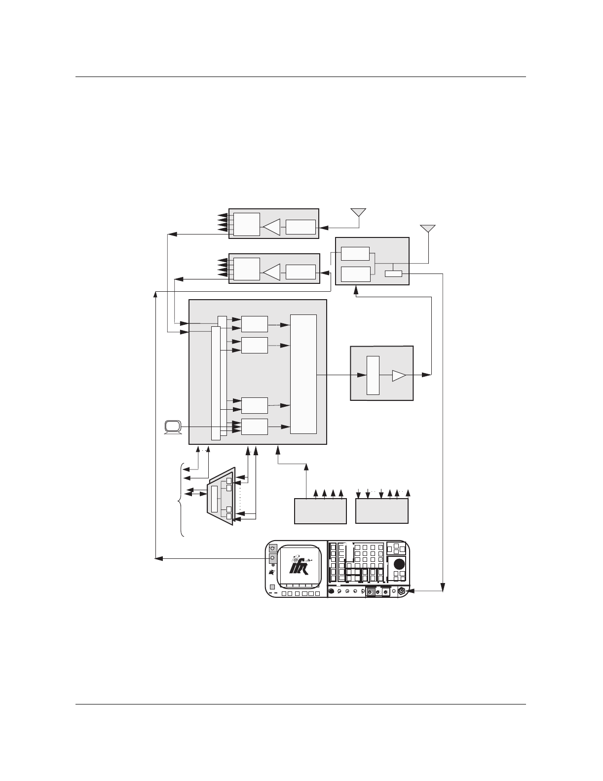
DRU receive tests 11-29
Wireless Solutions DualMode 800 Enclosure Maintenance Manual MTX08
RSSI offset calibration
The RSSI offset compensates for the overall receive path gain as measured
from the Receive Multicoupler (RMC) input to the TRU input. It compensates
for the cell site characteristics, such as the RMC and the receive path cabling.
Figure 11-6 shows the setup for the RSSI offset calibration.
Figure 11-6
RSSI offset setup
Note: IFR 1600 or any equivalent communications monitor can be used.
Diversity Receive
Main
Transmit / Receive
TRU Shelf
Other TRU
Shelves
Other TRU
Shelves LNA Preselect
Filter
Receive Multicoupler
1:8 Splitters
1:8
Splitter
LNA
Duplexer
RX Bandpass
Filter
TX Bandpass
Filter
TRU 8
TRU 2
TRU 7
TRU 1
1:8
Splitter Preselect
Filter
Receive Multicoupler
Integrated
Cellular
Remote
Module
(ICRM)
Data
L
I
N
K
P
P
P
To
MTX
Voice
P
Alarm
Inputs Outputs
Other TRU
Shelves
Alarm
Control Unit
High Stability
MasterOscillator
Data
•••• • •
Communications Monitor (IFR 1600)
INTENSIT
Y
POWER
DUPLEX
OUT
ON
F1 F2 F3 F4 F6F5
MODE
ANTENNA
FM /AM 1600S
AUX
IN
FM/AM
1600S
65W
MAX
65W
MAX
APPLIED
RF
RCVR
DPLX
AF
SCOPE
MTRS
AUTO
SGL
GO
STOP
PRINT
HOLD
SETUP
STORE
0
CE
DEL
8
5
2
SHIFT
RCL
7
4
1
#
^
v
9
6
3
Enter
^
v
+
-
Mu
km
.
TESTCONTROL
DATAENTRY
MEMORY EDIT SQLCH VOL
FIELD SELECT
^
v
< >
^v
< >
MIC/ACC SINAD AUDIO DEMOD VΩCOM AMP SCOPE T/R
IN/OUT IN IN OUT OUT 1KVDC/500V
AC MAX 2 AMPS
MAX
IN
200 VDC
MAX
200W
MAX
IN/OUT
BER
DMM
DATASCROLL
EXT MOD
STEP
SCRN
SCRN
GEN
GEN
ANLZ
Sniffer
VT100
•••• • •
Tx
Combiner
MCPAs
4:1 Combiner
MCPA Shelf

11-30 DRU tests
411-2051-500 Draft 00.01 November 1999
Step Action Observation
1 Put the DRU under test out of service at the
MTX.
2 Connect a low loss RF cable from the IFR output
Duplex 65W Max jack to the RMC input port A. The RF cable loss should be known and
will be used for calculation later.
3 Connect the interface terminal to the RS-232
port on the front panel of the TRU under test.
4 Place the transceiver in Debug mode by pressing
the BREAK key.
5 On the Debug terminal type “SET FS ON” and
type press the <RETURN> key.
If the command is not issued right-a-way then the
BREAK key may have to be typed again.
6 From the terminal, select the channel assigned
to the DRU under test by using the B command.
>B <return>
Enter the channel number
>XXXX
The DRU will request a channel number
( 1…799 or 991…1023 )
On a successful channel change, the
Channel and Synth Lock fields will
be updated:
Channel: xxxx (DRU channel
number indicated)
Synth Lock: YES (Sync Lock
changes to ‘YES’)
7 Ensure that the DRU configurations are as listed
in Table 11-3 for the RSSI characteristics test.
8 On the communications monitor, set the receiver
RF frequency to the frequency corresponding to
that of the TRU under test.
For an IFR 1600, by selecting the
transmitter frequency, the receiver
frequency will automatically be set.
9 Using the communications monitor, apply a -60
dBm on-channel RF signal modulated with a
1kHz tone at ±2.9 kHz deviation to the DRU
under test.
10 Use the P command to measure the RSSI signal
reading.
>P <return>
The DRU will prompt for the
measurement to query:
Enter R, SAT, ST, or A
- continued -

DRU receive tests 11-31
Wireless Solutions DualMode 800 Enclosure Maintenance Manual MTX08
Step Action Observation
11 Enter the “R” option to query the RSSI
measurement.
>R <return>
RSSI measurement is displayed and the
output message will show:
continuing Query..(hit return
to exit)
12 Check the RSSI measurement displayed on the
terminal screen and record it. RX RSSI : - 57.0
RX SAT : N
RX ST : N
13 Use the O command to enter the value of dB1=
(input level - measured RSSI reading - RF cable
loss value) as the RSSI offset for path A, antenna
1.
>O <return>
>A dB1 0 0
The RSSI offset should be kept to ±5 dB to keep
RSSI values between -130 dBm and -30 dBm.
Example:
Input level: -60dBm
Measured RSSI value: -57dBm
Typical RF cable loss: 1dB
then dB1 = -60 - (-57) - 1 = - 4dB
Enter path (A or B) and three separate
dB values (± 0…100).
14 On the communications monitor, change the RF
signal level as shown in Table 11-4 and record
the RSSI measurement from the Debug terminal.
Requirement as shown in Table 11-4
15 Change the Antenna path with the N command
to path ‘B’ from the Debug terminal.
>N <return>
The DRU will request an antenna path
choice. Enter path ( A,B, or DIV ).
16 Enter the antenna path
>B <return>
Change the connection to the RMC input port B
accordingly.
Current Receiver path: B
17 Repeat step 7 to step 12 for the new antenna
path.
- continued -

11-32 DRU tests
411-2051-500 Draft 00.01 November 1999
Step Action Observation
18 Use the O command to enter the value of dB4 =
(input level - measured RSSI reading - RF cable
loss value) as the RSSI offset for path B, antenna
4.
>O <return>
>B dB4 0 0
Antenna Port 1 2 3 4 5 6
RSSI offset dB1 0 0 dB4 0 0
19 For sectored sites only, perform the remaining
portion of this procedure. OMNI cells will only
have two antennas and need not perform the
following steps in this procedure.
20 Change the Antenna path with the N command
to path ‘A’ from the Debug terminal.
>N <return>
The DRU will request an antenna path
choice. Enter path (A,B, or DIV).
21 Enter the antenna path.
>A <return>
Current Receiver path: A
22 Change the antenna ports to 2 and 5 with the M
command from the Debug terminal.
>M <return>
The DRU will request the port numbers.
Enter a path A port number (1|2|3) and
a path B port number (4|5|6).
23 Enter the antenna ports as two numbers
separated by a space
>2 5 <return>
24 Repeat step 9 to step 18 for all radios being
tested.
Change the connection to the RMC input port
accordingly.
When using the O command to enter
the RSSI offset for path A, antenna port
2 and path B, antenna port 5, make sure
to re-enter the RSSI offset for path A,
antenna port 1 (dB1) and for path B,
antenna port 4 (dB4). For example:
>O
>A DB1 DB2 0
where DB2 = RSSI offset for port 2 and
DB1 = previous value set for port 1.
>O
>B DB4 DB5 0
where DB5 = RSSI offset for port 5 and
DB4 = previous value set for port 4.
- continued -

DRU receive tests 11-33
Wireless Solutions DualMode 800 Enclosure Maintenance Manual MTX08
Table 11-3 shows the DRU configuration for RSSI characteristics and Table
11-4 shows the RSSI measurement characteristics.
Step Action Observation
25 Change the Antenna path with the N command
to path ‘A’ from the Debug terminal.
>N <return>
The DRU will request an antenna path
choice. Enter path ( A,B, or DIV ).
26 Enter the antenna path.
>A <return>
Current Receiver path: A
27 Change the antenna ports to 2 and 5 with the M
command from the Debug terminal.
>M <return>
The DRU will request the port numbers.
Enter a path A port number (1|2|3) and
a path B port number (4|5|6).
28 Enter the antenna ports as two numbers
separated by a space.
>3 6 <return>
29 Repeat step 9 to step 18 for all radios being
tested.
Change the connection to the RMC input port
accordingly.
When using the O command to enter
the RSSI offset for path A, antenna port
3 and path B, antenna port 6, make sure
to re-enter the RSSI offset for path A,
antenna ports 1, 2 (dB1 and dB2) and
for path B, antenna ports 4, 5 (dB4 and
dB5). For example:
>O
>A DB1 DB2 DB3
where DB3 = RSSI offset for port 3,
DB2 = previous value set for port 2, and
DB1 = previous value set for port 1.
>O
>B DB4 DB5 DB6
where DB6 = RSSI offset for port 6,
DB5 = previous value set for port 5, and
DB4 = previous value set for port 4.
- End -

11-34 DRU tests
411-2051-500 Draft 00.01 November 1999
RSSI field specification: Nominal value ±3 dB
Table 11-3
DRU configuration for RSSI characteristics
TRU Configurations TX/RX Audio
SAT TX Tone
Gen Loop
back Compander WideBand
Data Detect
RSSI Audio
Status Audio
Sens
Command G I J K L P R T
RSSI
detect OFF OFF OFF ON OFF RSSI OFF -18.0
Table 11-4
RSSI measurement characteristics
RF signal input
(in dBm) RSSI measurement (in dBm)
Maximum Nominal Minimum
-60 -57 -60 -63
-70 -67 -70 -73
-80 -77 -80 -83
-84 -81 -84 -87
-90 -87 -90 -93
-100 -97 -100 -103

DRU receive tests 11-35
Wireless Solutions DualMode 800 Enclosure Maintenance Manual MTX08
SAT detect test
This test ensures that the DRU meets the minimum requirement of detecting a
Supervisory Audio Tone signal.
Step Action Observation
1 Ensure that the DRU configurations are as
listed in Table 11-1 for the SAT detect test.
2 Use the P command to query the SAT signal.
>P
The DRU will prompt for the signal to query:
Enter R, SAT, ST, or A
3 Enter the “SAT” option to query the SAT
signal.
>SAT
The RX SAT status shows: N
The output message shows:
continuing Query..(hit return
to exit)
4 Using the communications monitor, apply a
-90 dBm on-channel RF signal modulated
with a 5970 Hz tone at ±1.8 kHz deviation to
the DRU under test.
The RX SAT status on the screen should
show:
RX SAT: 0
5 Reduce the level of the RF signal until a “N”
is indicated at the RX SAT status on the
screen.
The RX SAT status on the screen shows:
RX SAT: N
6 Check the RF signal level on the
communications monitor. The RF signal level must be:
less than -105 dBm
7 Record the RF signal level on the test forms.
8 Using the communications monitor, apply a
-90 dBm on-channel RF signal modulated
with a 6000 Hz tone at ±1.8 kHz deviation to
the DRU under test.
The RX SAT status on the screen should
show:
RX SAT: 1
9 Reduce the level of the RF signal until a “N”
is indicated at the RX SAT status on the
screen.
The RX SAT status on the screen shows:
RX SAT: N
10 Check the RF signal level on the
communications monitor. The RF signal level must be:
less than -105 dBm
11 Record the RF signal level on the test forms.
12 Using the communications monitor, apply a -
90 dBm on-channel RF signal modulated
with a 6030 Hz tone at ±1.8 kHz deviation to
the DRU under test.
The RX SAT status on the screen should
show:
RX SAT: 2
- continued -

11-36 DRU tests
411-2051-500 Draft 00.01 November 1999
ST detect test
This test ensures that the DRU meets the minimum requirement of detecting a
Signaling Tone signal.
13 Reduce the level of the RF signal until a “N”
is indicated at the RX SAT status on the
screen.
The RX SAT status on the screen shows:
RX SAT: N
14 Check the RF signal level on the
communications monitor. The RF signal level must be:
less than -105 dBm
15 Record the RF signal level on the test forms.
- End -
Step Action Observation
1 Ensure that the DRU configurations are as
listed in Table 11-1 for the ST detect test.
2 Use the P command to query the ST signal.
>P
The DRU will prompt for the signal to query:
Enter R, SAT, ST, or A
3 Enter the “ST” option to query the ST signal.
>ST
The RX ST status shows: N
The output message shows:
continuing Query..(hit return
to exit)
4 Using the communications monitor, apply a
-90 dBm on-channel RF signal modulated
with a 10 kHz tone at ±7.2 kHz deviation to
the DRU under test.
The RX ST status on the screen should
show:
RX ST: Y
5 Reduce the level of the RF signal until a “N”
is indicated at the RX ST status on the
terminal screen.
The RX ST status on the screen shows:
RX ST: N
6 Check the RF signal level on the
communications monitor. The RF signal level must be:
less than -105 dBm
7 Record the RF signal level on the test forms.
8 Press the “Return” key from the terminal to
discontinue the measurement. The output message will show:
Query Status is OFF
Step Action Observation

DRU receive tests 11-37
Wireless Solutions DualMode 800 Enclosure Maintenance Manual MTX08
Setting RX audio level to site operational level
After the receive tests, ensure that the audio level recorded in the Receive
Audio Level test is the same as the site specific operational level. If the two
levels are different, perform the Receive Audio Level test and change the
receive audio level to the site specific operational level by using the T
command.
Set the RX audio sensitivity with the T command.
>T
The DRU will prompt as follows:
Enter TX or RX and a decimal dBm value (TX:-28...
-10);(RX:-28...-16)
Enter:
>RX -xx.x (change this value as required to obtain the operational
receive audio level)
Note: A change of 1 dBm is approximately a change of -0.27 kHz
deviation.
The Audio Sens RX status on the screen will show:
Audio Sens Rx: -xx.x (site specific operational level)
Use the Y command to perform a reset on the DRU after the tests.
>Y
At the command prompt, perform a warm reset on the DRU by entering:
>W
The DRU will return to its normal working condition after the reset.
Disconnect the interface terminal from the DRU.
At the MTX, put the DRU back to service.
11-38 DRU tests
411-2051-500 Draft 00.01 November 1999
Transmit RF output power test
This test measures the power output of the TRU, the MCPA and the transmit
path insertion loss. Since it interrupts service for the shelf and potentially
(depending on system configuration) the whole site, it should be used only
when a problem is suspected and then only during a low traffic period.
This section describes the Transmit RF output power test that can be
performed on the DualMode Radio Unit (DRU). The Transmit RF output
power test setup procedure must be performed before the test.
Transmit RF output power test setup procedure
1. At the MTX, busy and off-line the TRU under test.
2. Connect the interface terminal to the RS-232 port on the front panel of the
TRU under test. Verify that the DRU configurations for TRU power test
initial setup are as listed in Table 11-1.
Note: Ensure that the TRU transmitter is off.
3. Connect the receive input of the communications monitor to the antenna
port of the duplexer. Use a low loss double shielded cable, RG-214 or
equivalent. Figure 11-7 shows the connection setup for the RF output
power test.
Note: If you do not want to interrupt service, connect to the monitor port
of the duplexer instead. The measurement may not be as accurate because
the level is approximately 50 dB down with a tolerance of up to ±5 dB.
WARNING
RF radiation hazard
Do NOT disconnect any RF cables when transmitters are on.
CAUTION
Service interruption
The service of the shelf/site under test will be affected.
Perform the tests during low traffic period.

Transmit RF output power test 11-39
Wireless Solutions DualMode 800 Enclosure Maintenance Manual MTX08
Figure 11-7
Transmit RF output power test setup
Diversity Receive
Main
Transmit / Receive
TRU Shelf
Other TRU
Shelves
Other TRU
Shelves LNA Preselect
Filter
Receive Multicoupler
1:8 Splitters
1:8
Splitter
LNA
Duplexer
RX Bandpass
Filter
TX Bandpass
Filter
TRU 8
TRU 2
TRU 7
TRU 1
1:8
Splitter Preselect
Filter
Receive Multicoupler
Integrated
Cellular
Remote
Module
(ICRM)
Data
L
I
N
K
P
P
P
To
MTX
Voice
P
Alarm
Inputs Outputs
Other TRU
Shelves
Alarm
Control Unit
High Stability
MasterOscillator
Data
•••• • •
•••• • •
Communications Monitor (IFR 1600)
INTENSIT
Y
POWER
DUPLEX
OUT
ON
F1 F2 F3 F4 F6F5
MODE
ANTENNA
FM /AM 1600S
AUX
IN
FM/AM
1600S
65W
MAX
65W
MAX
APPLIED
RF
RCVR
DPLX
AF
SCOPE
MTRS
AUTO
SGL
GO
STOP
PRINT
HOLD
SETUP
STORE
0
CE
DEL
8
5
2
SHIFT
RCL
7
4
1
#
^
v
9
6
3
Enter
^
v
+
-
Mu
km
.
TESTCONTROL
DATAENTRY
MEMORY EDIT SQLCH VOL
FIELD SELECT
^
v
< >
^v
< >
MIC/ACC SINAD AUDIO DEMOD VΩCOM AMP SCOPE T/R
IN/OUT IN IN OUT OUT 1KVDC/500V
AC MAX 2 AMPS
MAX
IN
200 VDC
MAX
200W
MAX
IN/OUT
BER
DMM
DATASCROLL
EXT MOD
STEP
SCRN
SCRN
GEN
GEN
ANLZ
Sniffer
VT100
Tx
Combiner MCPAs
4:1 Combiner
MCPA Shelf

11-40 DRU tests
411-2051-500 Draft 00.01 November 1999
4. From the terminal, select the channel assigned to the TRU under test by
using the B command.
>B
The TRU will request a channel number. Enter the channel number for the
frequency assigned to the DRU under test (1...799 or 990...1023). Refer to
Appendix A for the channel-to-frequency conversion information.
>xxxx
On a successful channel change, the Channel and Synth Lock fields will
be updated:
Channel: xxxx (DRU channel number indicated)
Synth Lock: YES (Sync Lock changes to ‘YES’)
5. On the communications monitor, set the transmit RF frequency to the
frequency corresponding to that of the TRU under test.
6. Proceed with the RF output power test.
Requirements on the Transmit RF output power test
When performing the Transmit RF output power test, make sure that power
initialization has been performed (refer to Chapter 1). Also, take into account
the number of channels supported by the MCPA and the component (cable,
duplexer) loss along the transmit path.
Table 11-5 lists the maximum per-channel power levels per carrier measured
at the output port of the MCPA shelf for different channel counts and MCPA
combinations in a DualMode 800 Enclosure. The power per channel calculation
is based on the following assumption:
• output of TRU at +15 dBm and nominal gain at -12 dB, giving an overall
TRU output of +27 dBm
Figure 11-8 shows the per-channel transmit power level at the output of each
component for a 24-channel cell/sector using two MCPA modules.
Table 11-5
DualMode 800 Enclosure per-carrier power level at the output port of the MCPA shelf
1 MCPA module 2 MCPA modules
8 channels 12.50 W 25.00 W
16 channels 6.25 W 12.50 W
24 channels 4.17 W 8.33 W
32 channels 3.12 W 6.25 W
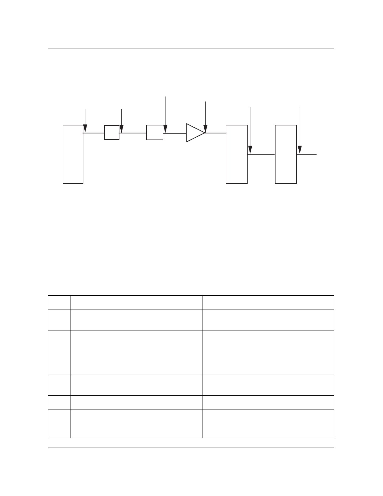
Transmit RF output power test 11-41
Wireless Solutions DualMode 800 Enclosure Maintenance Manual MTX08
Figure 11-8
Transmit power level of a DualMode 800 Enclosure with 24-channel per cell/sector using two
MCPA modules
Transmit RF output power test
This test ensures that the output power level of the TRU, the MCPA, and the
transmit path loss are within specifications.
Step Action Observation
1 Ensure that the TRU configurations are as
listed in Table 11-1 for the Power Output test.
2 Turn on the TRU transmitter with the C
command
>C
The PA status should be as follows:
PA: on
TxPwrIndex: 0
TxPwrStep: 4.00
MaxTxPwr: 15.00
3 Measure the output power of the channel on
the communications monitor. Power level should be within site
specifications (refer to Table 11-5).
4 Record the power level on the test forms.
5 Turn off the TRU transmitter with the C
command.
>C
The PA status on the screen will show:
PA: off
+5.75 dBm
-1.34 dBm +38.3 dBm
(6.7 watts)
(Note 5)
+27 dBm
(-0.25 dB) (-0.2 dB)
(-6.25 dB) (-0.7 dB) (-0.1 dB)
(-0.4 dB)
Transmit Receive Unit
(TRU)
TX Combiner
(at the back of
TRU shelf)
Combiner
Duplexer
Antenna panel
Lightning arrestor
TX/RX
Antenna
4:1
Notes: 1.
2.
3.
4.
5.
Typical gains and losses shown — not maximum or minimum.
Per-channel TX power level shown with TRU output at +27 dBm.
MCPA gain includes the MCPA module gain and the splitter,
combiner, and cable losses within the MCPA shelf.
Additional loss due to amplitude/phase imbalance (typically 0 to
0.5 dB) not shown.
Output power at duplexer antenna port may be 0 to 0.5 dB lower
due to amplidtue/phase imbalance.
8:1
MCPA
LMR-400
+53.1 dB
(Notes 3
and 4)(-21 dB)
+39.2 dBm
(8.3 watts) +37.8 dBm
(6.0 watts)
(Note 5)
(-0.84 dB) (-0.25 dB)

11-42 DRU tests
411-2051-500 Draft 00.01 November 1999
Setting TRU power step size and Max power to site operational level
After the output power tests, ensure that the TRU power step size and the
TRU Max power are set back to the site specific operational level. Check the
TRU power step size setting previously defined for the site. Set the TRU
power step size setting to the site specific operational step size setting with
the U command from the interface terminal.
Set the TRU Power Step with the U command.
>U
The TRU will prompt for a power step size:
1..4
Enter:
>x.xx (change this value as required to obtain the operational power
step size)
The power step size on the screen will show:
TxPwrStep: x.xx (site specific power step size)
Check the TRU Max power setting previously defined for the site. Set the
TRU output power to the site specific operational power with the F command
from the interface terminal.
Set the TRU Max Power with the F command.
>F
The TRU will prompt for a power level:
-1.0...27.0 in dBm
Enter:
>xx.x (change this value as required to obtain the operational
output power level)
The MaxTxPwr status on the screen will show:
MaxTxPwr: xx.xx (site specific operational level)
Use the Y command to perform a reset on the TRU after the tests.
>Y
At the command prompt, perform a warm reset on the TRU by entering:
>W
The TRU will return to its normal working condition after the reset.
Disconnect the interface terminal from the TRU.
At the MTX, put the TRU back to service.
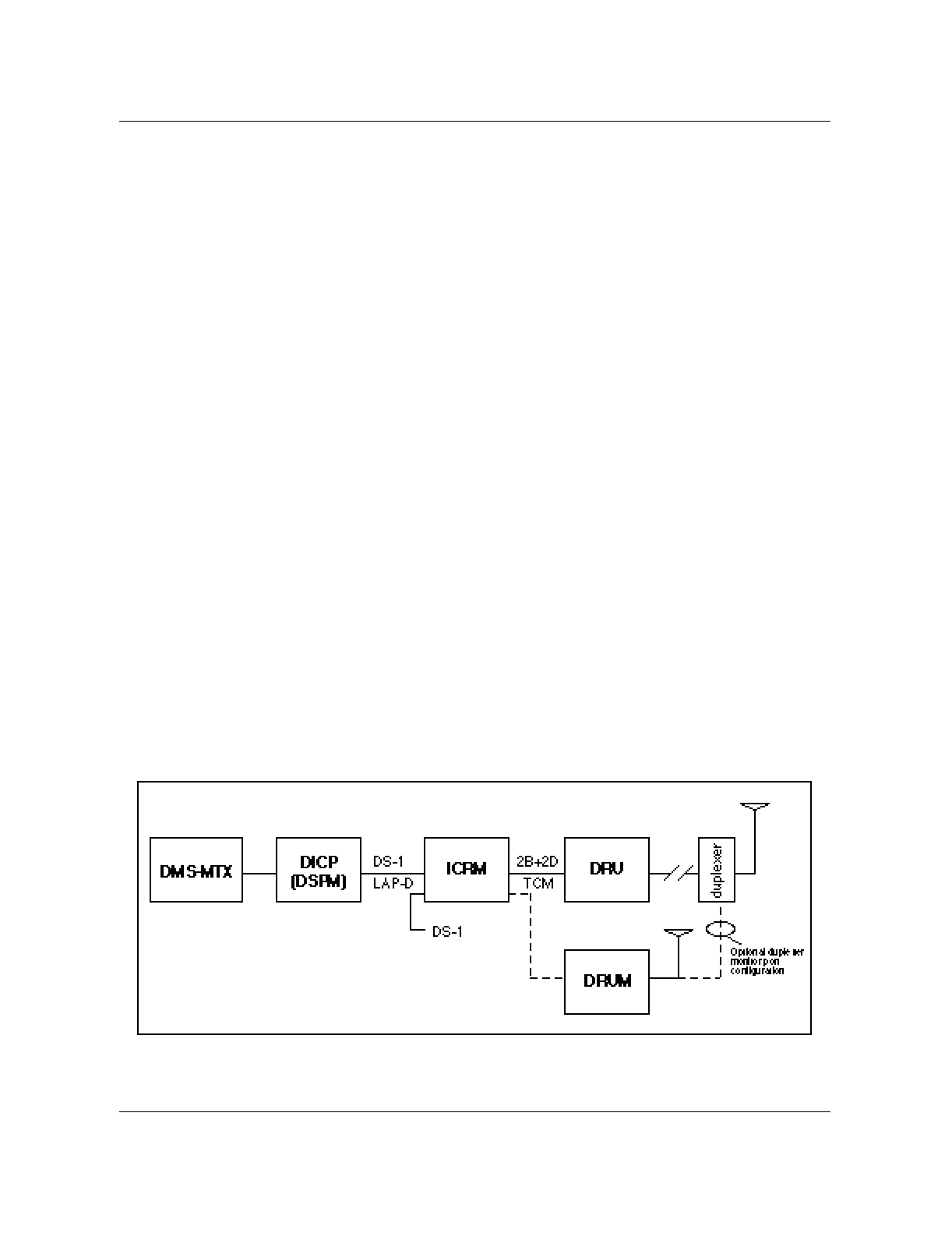
DRU digital tests 11-43
Wireless Solutions DualMode 800 Enclosure Maintenance Manual MTX08
DRU digital tests
This section describes the digital tests that can be performed on the
DualMode Radio Unit (DRU) and other system components to verify TDMA
operation. A DualMode Radio Unit Monitor (DRUM) is required to perform
the Bit Error Rate test and a TDMA or a Dual Mode cellular phone is required
to perform the TDMA call test. The test requires operator commands initiated
at the DRU, DRUM and MTX.
Digital test considerations
A 2-way splitter located on the DRUM is used to combine the bi-directional
link from the duplexer and from the DualMode Cell Site Monitor (DCSM) to
give a single interface for both. The 2-way splitter connects to either an
antenna or a duplexer monitor port to provide an RF interface to the DRUs.
The NTAX40CA DRUM uses the antenna connection; while the NTAX40DA
DRUM uses the duplexer monitor port.
A Bit Error Rate loopback test is initiated at the MTX on an in-service
(INSV) DRU that has been taken out of call processing mode by the test being
run. The test is carried out over the entire transmission loop from the MTX
Digital Signal Processing Module (DSPM) through a DRU to the DRUM.
Measurements of a Pseudo-Random Bit Stream are taken in both the near-to-
far and far-to-near directions. Bi-directional transmit and receive tests are
performed; uni-directional tests are automatically performed only if the bi-
directional test fails. Figure 11-9 shows the digital loopback paths.
Note: The TRU3 does not support this loopback test method. It only
supports the on-site BER test method.
Figure 11-9
Digital loopback paths

11-44 DRU tests
411-2051-500 Draft 00.01 November 1999
Bit error rate test at the MTX switch
Bit Error Rate (BER) is defined as the ratio of erroneous bits to the total
number of received bits in a transmission system. Typically, BER tests are
performed on suspect equipment. However, external factors such as strong
electromagnetic conditions, multi-path effects and environmental conditions
like lightning may also cause high BER levels and need to be considered
when a BER test fails.
In the outbound direction (from Digital Signal Processing Module to
DualMode Radio Unit), the BER test generates a pseudo-random bit stream
(PRBS) onto the selected TDMA time slot. In the inbound direction, the BER
test expects to receive the same bit pattern. After a short self-synchronization
time period, the bit error rate is measured.
Note: The TRU3 does not support this test (that is, the MRBT test).
Step Action Observation
1 Ensure that the following tables have been
datafilled.
Table CTTPARMS
Table PMLOADS
Table TERMATTR
Table CSMINV
Tuples shown are examples only. They may
look different on your screen.
Table CTTPARMS has a tuple for the cell
under test and range TESTNAME says
“MRBT”
TABLE CTTPARMS
PARMNAME TSTPARMS
---------------------------------------------
MRBT MRVT MRBT 6000000 6000 6000 NOSTOP
TABLE: PMLOADS
LOADNAME DEVICE
-----------------------------------------------
DM2_AE25 D000PMLOADS
TABLE: TERMATTR
ATTRIBUTE PEC_CODE LOAD PADPEC CSPM HWTYPE
----------------------------------------------
AE25 AX40DA DM2_AE25 NOPAD ICRM DRUM
TABLE: CSMINV
CSMKEY MIN SERNO TERMATTR CARD PORT ALARMPT
-----------------------------------------------
495 0 214 234 0095 142 571 AE25 8 15 0
2 Ensure that the DRUM is in service.
>MAPCI;MTC;MTX
>POST CELL {cell #};CTU {ctu #}
Verify that the DRUM indicates INSV.
- continued -

DRU digital tests 11-45
Wireless Solutions DualMode 800 Enclosure Maintenance Manual MTX08
3 Enter the log reporting system and setup a
device to report MTX 230 logs.
>LOGUTIL
>ADDREP <device name> MTX 230
>STARTDEV <device name>
>QUIT
LOGUTIL
1 report added
<device name> started
>
4 Enter the DRU POST level:
>POST VCH ALL or POST VCH {no.}
Post position is displayed on the MAP
terminal.
5 Perform the bit error rate test on the DRU
from the MTX.
>TST MRBT MRBT 2
Test submitted, watch LOGs for results.
Note:
MRBT test on the first Voice channel
must be completed before going to the next
Voice channel.
6 Review the results on the Log device started
earlier. A sample of the log is displayed right. Log MTX 230 printed on the log device.
MTX230 OCT23 12:52:14 9408 INFO CTE Test
results
TESTNAME: MRBT
CELL = 495 VCH 6 DRU PRTN = Z
CTTPARMS: MRBT TDMA CHANNEL: 2
RESULTS: TEST STAGE: TX
STATUS: PASSED
REASON:
# BITS TRANSMITTED: 6000000
# BIT ERRORS: 9
BER: 9.0*10E-6
# RESYNCS: 0
The bit error rate must be less than 0.6% or
less than 36000 errors in 6000000.
7 Record the results on test forms.
8 Test the next DRU by typing:
>NEXT or POST VCH (no.)
The next DRU will be posted.
9 Repeat steps 5 to 7 for testing the next DRU.
10 When tests are complete, turn logs off by
entering:
>LOGUTIL
>STOPDEV <device name>
>DELREP <device name> MTX 230
>QUIT
LOGUTIL
Device Stopped
1 Report deleted
>
- End -
Step Action Observation
11-46 DRU tests
411-2051-500 Draft 00.01 November 1999
Bit error rate test at the cell site
The BER test performed at the cell site verifies the BER performance of the
DRU and the paths between the DRU and the communications monitor. It
does not verify the BER performance of the links between the DRU and the
DSPM.
In the inbound (RX) direction (from the communications monitor to the
TRU), the communications monitor generates a pseudo-random bit stream
(PRBS) onto the selected TDMA time slot of the TRU. This PRBS is looped
from the receiver of the TRU to the transmitter of the TRU and sent back to
the communications monitor. In the outbound (TX) direction, the
communications monitor expects to receive the same bit pattern. After a short
self-synchronization time period, the bit error rate is measured.
Service impacts
This BER test causes a reduction in the receive performance of the shelf
containing the TRU under test because of the loss of receive diversity.
The TRU transmit and receive tests must be performed before the BER test to
verify the TRU’s transmit and receive paths. This is because the TRU uses an
RF loopback to access the base-band receive signal. Failure to verify the
TRU transmit and receive paths may result in invalid test data.
Figure 11-10 shows the BER test setup at the cell site
Note: The sniffer port is at a level of -50 dBm lower than the level at the
antenna port of the duplexer. Make sure that this level meets the minimum
input level requirement of your communications monitor. If the level is
lower than the minimum requirement, connect the input of the
communications monitor to the antenna port of the duplexer. In this case,
the entire cell/sector will be out of service for the duration of the test.
CAUTION
Service interruption
The service of the shelf housing the TRU under test will be
affected. Perform the tests during low traffic period.
WARNING
RF radiation hazard
Do NOT disconnect any RF cables when transmitters are on.
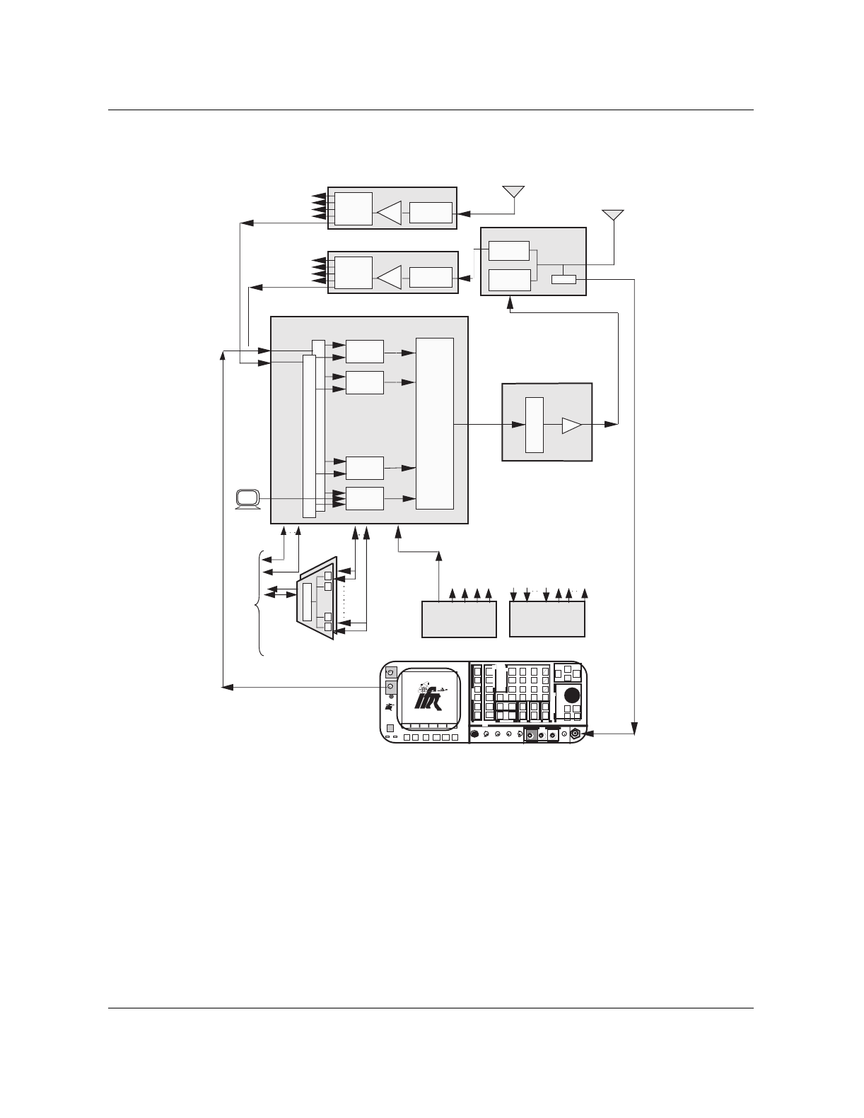
DRU digital tests 11-47
Wireless Solutions DualMode 800 Enclosure Maintenance Manual MTX08
Figure 11-10
BER test setup at the cell site
Note: This test works with an IFR1900 or HP8935 communications
monitor with the required software. It does not work with an older IFR or
HP model.
Diversity Receive
Main
Transmit / Receive
TRU Shelf
Other TRU
Shelves
Other TRU
Shelves LNA Preselect
Filter
Receive Multicoupler
1:8 Splitters
1:8
Splitter
LNA
Duplexer
RX Bandpass
Filter
TX Bandpass
Filter
TRU 8
TRU 2
TRU 7
TRU 1
1:8
Splitter Preselect
Filter
Receive Multicoupler
Integrated
Cellular
Remote
Module
(ICRM)
Data
L
I
N
K
P
P
P
To
MTX
Voice
P
Alarm
Inputs Outputs
Other TRU
Shelves
Alarm
Control Unit
High Stability
MasterOscillator
Data
•••• • •
Communications Monitor (IFR 1900)
INTENSIT
Y
POWER
DUPLEX
OUT
ON
F1 F2 F3 F4 F6F5
MODE
ANTENNA
FM /AM 1600S
AUX
IN
FM/AM
1600S
65W
MAX
65W
MAX
APPLIED
RF
RCVR
DPLX
AF
SCOPE
MTRS
AUTO
SGL
GO
STOP
PRINT
HOLD
SETUP
STORE
0
CE
DEL
8
5
2
SHIFT
RCL
7
4
1
#
^
v
9
6
3
Enter
^
v
+
-
Mu
km
.
TESTCONTROL
DATAENTRY
MEMORY EDIT SQLCH VOL
FIELD SELECT
^
v
< >
^v
< >
MIC/ACC SINAD AUDIO DEMOD VΩCOM AMP SCOPE T/R
IN/OUT IN IN OUT OUT 1KVDC/500V
AC MAX 2 AMPS
MAX
IN
200 VDC
MAX
200W
MAX
IN/OUT
BER
DMM
DATASCROLL
EXT MOD
STEP
SCRN
SCRN
GEN
GEN
ANLZ
Sniffer
VT100
•••• • •
Tx
Combiner
MCPAs
4:1 Combiner
MCPA Shelf

11-48 DRU tests
411-2051-500 Draft 00.01 November 1999
Step Action Observation
1 Connect the test setup as shown in Figure
11-10.
2 Set up the communications monitor for BER
measurement.
Refer to the user’s manual of your
communications monitor for the setup
procedure.
Note:
Set the output of the communications
monitor to -110 dBm.
3 Set up the TRU as listed below:
>set LT off
>set PATYPE NONE
>set PERS TTC
>set CHANNEL xxxx (the B command)
>set TXPOWIDX 0 (the E command)
>set BCH loop off (the J command)
>set RF loop on (the J command)
>set PA on (the C command)
Note:
You can also use the Fullscreen mode
to set up the TRU.
4 Press the appropriate key (for example: GO,
START) on the communications monitor to
begin the BER test.
The bit error rate must be less than 3% when
output level of the communications monitor is
at -110 dBm.
Record the test result when the PRBS (Total
bits generated) reaches around 1,000,000
bits.
If BER is out of specifications, replace the
TRU and perform the test again. If problem
persists, perform troubleshooting.
5 Perform the test on the other timeslots of the
TRU.
Use the Set Slot (H) command to change the
slots. Remember to change the settings on
the communications monitor accordingly.
Record the test result.
6 Normalize the system. The A-side splitter on the TRU shelf is
connected back to the RMC output.
7 Connect the output of the communications
monitor to the B-side splitter on the TRU
shelf and perform the test (Steps 2 to 5) on
the B-side receiver of the TRU.
Record the test result.
8 After completing the test on the B-side
receiver of the TRU, normalize the system. The B-side splitter on the TRU shelf is
connected back to the RMC output.
- End -

DRU digital tests 11-49
Wireless Solutions DualMode 800 Enclosure Maintenance Manual MTX08
TDMA modulation accuracy test
The TDMA modulation accuracy test measures the π/4 DQPSK modulation
of the signals received from the TRU. To perform this test, you must use a test
equipment that can measure TDMA modulation accuracy, such as the
IFR1600 with TDMA software.
Note: The IFR1600 is used as a reference in this testing procedure. If you
are using another model of test equipment, refer to the user manual of that
equipment for the appropriate test setup and display.
Step Action Observation
1 Connect a VT100 (or equivalent) terminal to
the RS-232 port on the front panel of the
TRU under test.
2 By pressing the “Break” key on the terminal
keyboard, you can access the command line
mode.
The terminal will display (the TRU2 display is
shown as an example):
TRU Terminal Interface
(C) Copyright 1990,1991 Bell
Northern Research, Inc.
>
3 At the prompt (>), type:
>set lt off
4 Type:
>set pa off
The TRU transmitter is turned off.
This step ensures that the TRU is not
radiating RF power when disconnecting the
RF cable.
5 Connect the TRU under test through the
sniffer port of the duplexer to the input
connector of the test equipment (the T/R port
on the IFR1600).
6 Select the Modulation Accuracy function on
the test equipment.
For the IFR1600:
(i) select the ‘RCVR’ function with the IFR
MODE key
(ii) press the ‘F5’ key that is labeled ‘Sp Tst’
(iii) select ‘MODULATION ACCURACY’ by
pressing the ‘4’ key from the Data Entry
Keys.
The Modulation Accuracy display screen on
the IFR1600 shows:
MODULATION ACCURACY
CHANNEL 1
I/Q OFFSET=
FREQUENCY ERROR=
RMS PHASE ERROR=
RMS MAGNITUDE ERROR=
RMS ERROR VECTOR MAGNITUDE=
- continued -

11-50 DRU tests
411-2051-500 Draft 00.01 November 1999
7 On the test equipment, enter the channel
number that is to be tested.
For the IFR1600:
(i) use the Data Entry Keys to input the
channel
(ii) press the green ‘ENTER’ key to enter the
input.
8 On the terminal, type:
>set pers ttc
Personality configuration was successful.
The personality of the TRU changes to a
TDMA Traffic Channel.
9 Type:
>set channel xxxx
“xxxx” is the channel number of the TRU
under test.
Channel change was successful.
The channel of the TRU changes to the
desired number.
10 Type:
>set txpowidx 0
PA power change was successful.
The power index of the TRU changes to 0.
11 Type:
>set maxtxpow 15
Set Max power (input value and
value used): 15.0 15.0
PA Max Power (dBm): 15.0
The output power of the TRU changes to
27.0 dBm.
12 Type:
>run inject to dsp 1 52 b6 0 0
1
13 Type:
>set pa on
Status change was successful.
The TRU transmitter is turned on.
- continued -
Step Action Observation

DRU digital tests 11-51
Wireless Solutions DualMode 800 Enclosure Maintenance Manual MTX08
14 Start the test by pressing the F1 function key
labeled “RUN” on the IFR1600. (For the
operation of other types of test equipment,
refer to their user manuals.)
The following will be measured in this test:
I/Q Offset—20 x Log of the I/Q offset
magnitude indicates the amount of carrier
feed through.
Frequency Error—Difference between the
received carrier frequency and the ideal
carrier frequency.
RMS Phase Error—RMS value of the
absolute phase errors.
RMS Magnitude Error—RMS value of the
difference between the ideal magnitude and
the received magnitude.
RMS Error Vector Magnitude—RMS value of
the magnitude of the error vectors.
Test results will be displayed as follows:
MODULATION ACCURACY
I/Q OFFSET= (less than -30 dBc)
FREQUENCY ERROR= (+220 to -220
Hz)
RMS PHASE ERROR= (N/A)
RMS MAGNITUDE ERROR= (N/A)
RMS ERROR VECTOR MAGNITUDE= (less
than 12.5%)
15 Repeat Step 14 ten times and take the
average over the ten readings.
16 Once the test is completed, a π/4 DQPSK I/Q
plot can be performed by pressing the “F2”
function key on the IFR1600.
Note
: For more information on plotting
results, see the IFR1600 dual mode cellular
system analyzer manual. (For the operation
of other types of test equipment, refer to their
user manuals.)
17 Type:
>set pa off
Status change was successful.
The TRU transmitter is turned off.
18 Disconnect the test equipment from the
sniffer port of the duplexer.
19 Type:
>execute reset
This command removes the run inject
command and resets the TRU.
20 Disconnect the terminal interface from the
TRU.
- End -
Step Action Observation

11-52 DRU tests
411-2051-500 Draft 00.01 November 1999
TDMA call test
This test is used to verify the origination and termination of a digital call
through the DRU under test.
Step Action Observation
1 Originate a call with a TDMA cellular phone.
It may be necessary to make several calls
before the system selects the DRU under
test.
The LED display on the front panel of the
TRU will indicate that the DRU is selected.
2 Check that the audio quality of the call is
good.
3 Terminate the call. The LED display on the front panel of the
TRU should indicate that the call is
terminated by returning the DRU to the idle
state.

12-1
Wireless Solutions DualMode 800 Enclosure Maintenance Manual MTX08
Enclosure maintenance 12
Field Replaceable Unit (FRU)
The components of a DualMode 800 Enclosure are not designed to be
repaired in the field. The only maintenance that can be performed is to replace
components or the Field Replaceable Units (FRU). Refer to the DualMode
800 Enclosure Troubleshooting Guide, 411-2051-900, to determine if a
component needs to be replaced. Table 12-1 lists all the FRUs and their
Product Engineering Codes (PEC) or Common Product Codes (CPC).
Note 1: L/L — Like for Like (Advance replacement or mail-in)
M/O — Merchandise Order/Consumable items (items that are
disposable and not repairable, such as light bulbs, fuses, filters)
Note 2: For L/L units, please contact your Nortel Networks Customer
Service Operations (CSO) office for replacement.
For M/O items, please contact Nortel Networks Wireless Supply and
Demand office or purchase the items locally if available.
Note 3: Cables are M/O items. They are not listed in this table. If you
need to replace a cable, check the PEC/CPC on the cable or contact Nortel
Networks Wireless Supply and Demand office.
Table 12-1
DualMode Urban field replaceable units
Description PEC/CPC Service Remark
Rack Interface Panel (RIP) 1 NTL102AA L/L
Rack Interface Panel (RIP) 2 NTL102AB L/L
Rack Interface Panel (RIP) 3 NTL102AC L/L
Circuit Breaker 10A A0666060 M/O
Circuit Breaker 15A A0666061 M/O
Circuit Breaker 50A A0734636 M/O

12-2 Enclosure maintenance
411-2051-500 Draft 00.01 November 1999
Circuit Breaker 120A A0381990 M/O
Power Filter PCP NTFB14AA M/O
Duplexer, B Band NTFC04AC L/L
Duplexer, Full Band NTFC04AD L/L
Termination, 50-ohm A0689593 M/O
Multi-Channel Power Amplifier (MCPA) Shelf NTL107AC L/L
4:1 Combiner assembly NTL107AE L/L
MCPA Module 110 Watt NTL107AA L/L
MCPA Initialization Software NTFC07BC L/L
Transmit Receive Unit (TRU) Shelf NTFC05AG L/L
Fan unit module NTFB24AA M/O
Fan module PCP NTFB25AA M/O
Transmit combiner 800 module NTLA7106 M/O
TRU2 NTAX98AA L/L
TRU3 NTAW99AA L/L
Alarm Control Unit (ACU) NT3P89CA L/L
Output Contact card NT3P20EA L/L
Enhanced ACU Input card NT3P20FB L/L
High Stability Master Oscillator (HSMO) NT3P89DA L/L
DualMode Cell Site Monitor (DCSM) NT3P70BC L/L
Enhanced Receive Multicoupler (ERMC) — 8
ports NT3P20XD L/L
ERMC 8 Port Expansion Kit NT3P20XB L/L For NT3P20XD to expand
to 16 ports
ERMC — 16 ports NT3P20XC L/L
Integrated Cellular Remote Module (ICRM)
shelf NTTG86AA L/L
Table 12-1
DualMode Urban field replaceable units (continued)
Description PEC/CPC Service Remark

Field Replaceable Unit (FRU) 12-3
Wireless Solutions DualMode 800 Enclosure Maintenance Manual MTX08
Remote Module Digital Port (RMDP) card NT8X47CA L/L
Remote Module Time Switch Controller
(RMTC) NTAX88CA L/L For ICRMO+ and ICRM+
DS1 Interface card NT6X50AB L/L Not applicable to ICRMO+
PCM30 (E1) Interface card NT6X27BB L/L For ICRMO+
Power convertor NT2X70CA L/L
Alarm (RMAC) card NTAX92AA L/L Located in Remote Module
Frame Supervisor (RMFS)
TCM-RS232 Conversion (RMTP) card NTAX91AA L/L Located in RMFS
Rectifier Shelf NTL106AB L/L
Rectifier Module NTL106AA L/L
Power Control Shelf NTTF60AA L/L
Battery Compensation Module NTTF60AB L/L
Low Voltage Disconnect card NTTF60AC L/L
Channel Service Unit (CSU) 4-Slot Shelf NTLA7011 L/L
Shelf Interface Unit (SIU) for 4-Slot Shelf NTLA7013 L/L
T-Smart T1 SIU card A0383869 L/L
E-Smart E1 SIU card NTLA7012 L/L
Solar Shield Kit NTTF12AB L/L
Table 12-1
DualMode Urban field replaceable units (continued)
Description PEC/CPC Service Remark
12-4 Enclosure maintenance
411-2051-500 Draft 00.01 November 1999
General precautions
There are some general precautions that need to be aware of when replacing
components.
RF radiation hazard
Radio Frequency (RF) radiation is hazardous to anyone working in the cell
site. Before removing any RF cable, ensure that the related power amplifier is
turned off. All RF cables should be connected properly and all unused RF
ports should be terminated with an appropriate terminator.
Electrostatic Discharge (ESD) control
When handling any circuit board, take care to prevent damage from static
discharge. Observe the following rules.
1. To prevent electrostatic discharge, do not attach ribbon cables to circuit
boards until the circuit boards are in place.
2. To dissipate any static charge, wear a wrist strap in contact with the skin.
3. Connect the wrist strap ground cord to the equipment cabinet ground.
Cable/connector identification
Label all cables and connectors before disconnecting them from any cell site
equipment. This will minimize the time required for tracing the connections
and also reduce the possibility of incorrect connections.
CAUTION
Do NOT disconnect any RF cables when transmitters are on.
CAUTION
Do not let the circuit board come into contact with clothing at
any time, as the grounding strap cannot dissipate static charges
on fabrics.

Replacing faulty common equipment (CE) units 12-5
Wireless Solutions DualMode 800 Enclosure Maintenance Manual MTX08
Replacing faulty common equipment (CE) units
For the replacement of a common equipment unit, use the following procedure:
1. At the MTX, put the cell site or the unit out-of-service as required.
2. If replacing the Rack Interface Panel (RIP), switch off the supply to
the bay at the rectifier. If replacing other units, switch off both the ‘A’
and ‘B’ circuit breakers to that unit at the RIP.
3. Label and disconnect the cables/connectors connected to the unit.
4. Remove the screws mounting the unit to the bay and then remove the unit
from the bay.
5. Replace a new or known working unit on to the bay and fix it with the
mounting screws.
6. Reconnect the cables/connectors to their appropriate locations. Ensure
that they are connected properly.
7. Switch on the circuit breakers to the unit at the RIP or switch on the
power supply to the RIP at the rectifier.
Note: For the DCSM, program the mobile unit of the replacement DCSM
to the same parameters as the existing mobile unit after switching on the
power supply. Refer to Chapter 1, Equipment operation, for the
programming procedure.
8. At the MTX, ensure that the datafill information on the replacement unit
is correct.
9. At the MTX, put the cell site back into service.
10. Verify that the replacement unit is functioning correctly.
11. Return the faulty unit to your Nortel Networks Customer Service
Operations office for repair.
CAUTION
Service interruption
The enclosure may be completely out-of-service when a unit
such as the RIP, the HSMO, or the ICRM is removed. Replace
these units during low traffic period.
CAUTION
Hot insertion replacement may cause damage to the
components and a possible service interruption.
12-6 Enclosure maintenance
411-2051-500 Draft 00.01 November 1999
Replacing faulty radio frequency (RF) units
For the replacement of a radio frequency (RF) unit, use the following procedure:
1. At the MTX, put the cell site or the unit out-of-service as required.
2. If replacing the Rack Interface Panel (RIP), switch off the supply to
the RIP at the rectifier. If replacing a TRU or MCPA shelf, switch off
the circuit breaker to that unit at the RIP.
3. Label and disconnect the cables/connectors connected to the unit.
4. Remove the screws mounting the unit to the frame and then remove the
unit from the frame.
5. Replace a new or known working unit on to the frame and fix it with the
mounting screws.
6. Reconnect the cables/connectors to their appropriate locations. Ensure
that they are connected properly.
7. Switch on the circuit breaker to the unit at the RIP or switch on the power
supply to the RF Frame at the power plant.
8. At the MTX, ensure that the datafill information on the replacement unit
is correct.
9. At the MTX, put the cell site back into service.
10. Verify that the replacement unit is functioning correctly.
11. Return the faulty unit to your Nortel Networks Customer Service
Operations office for repair.
CAUTION
Service interruption
The enclosure may be completely out-of-service when a unit
such as the RIP, a duplexer, or a MCPA is removed. Replace
these units during low traffic period.
CAUTION
Hot insertion replacement may cause damage to the
components and a possible service interruption.

Replacing faulty radio frequency (RF) units 12-7
Wireless Solutions DualMode 800 Enclosure Maintenance Manual MTX08
Replacing the TRU or MCPA shelf
The channels associated with the TRU or MCPA shelf should be out-of-
service during the off-line replacement. This is of major significance if it is
supporting the control channel of the site/sector. In that case, ensure the
system switches to a back-up channel.
Follow the procedure when replacing a TRU or MCPA shelf:
1. At the MTX, put the affected channels out-of-service.
2. Switch off the circuit breaker of the shelf at the RIP.
3. Label and disconnect the cables/connectors connected to the backplane of
the shelf.
4. Remove the TRUs or MCPA modules from the shelf.
5. Loosen the screws mounting the shelf to the RF frame and then remove
the shelf from the frame.
6. Replace a new or known working shelf on to the frame and fix it with the
mounting screws.
7. Replace the TRUs or MCPA modules back to the shelf and fix them with
the mounting screws.
8. Reconnect the cables/connectors to their appropriate locations on the
backplane of the shelf. Ensure that they are connected properly.
9. Switch on the circuit breaker of the shelf at the RIP.
10. At the MTX, put the affected channels in-service.
General rules for replacing a TRU or an MCPA module
The following rules must be followed when replacing a TRU or a MCPA
module:
• Pull evenly and firmly on the module handle to pull the module out of the
backplane connector. If excessive resistance is felt, stop and investigate
the reason.
• Slide the module directly and squarely into and out of the shelf guide slot.
• When inserting a module, carefully line up the module connectors and the
backplane connectors before trying to seat the module. The module
should seat easily into the shelf. Do not force the module into the shelf. If
the connectors are out of alignment, damage to the module and the
backplane will result.
Replacing the TRU
The Transmit Receive Unit (TRU) can be changed with the DC power on.
The channel associated with the TRU should be out-of-service during the off-
line replacement. This is of major significance if it is a control or locate
channel. In that case, ensure the system switches to a back-up channel.

12-8 Enclosure maintenance
411-2051-500 Draft 00.01 November 1999
Follow the procedure when replacing a TRU:
1. At the MTX, put the affected channel(s) out-of-service.
2. Loosen the tab at the top edge of the TRU and move it away from the
TRU.
3. Using the handle on the front of the TRU, gently pull the module out of
the backplane connector and then slide it out of the shelf.
4. Place the replacement unit in the shelf guides.
5. Slide the unit into the shelf until it reaches the backplane connector.
6. Line up the TRU connector with the backplane connector and carefully
mate the connectors. Do not force the module into the shelf. If this is not
done with care, the pins of the connector may be damaged.
7. Move the tab over the top edge of the TRU and tighten the tab.
8. Perform the operational checks on the TRU.
9. At the MTX, put the channel/DRU in-service.
10. Perform a call through test on the TRU replaced. It may be necessary to
make several calls before the system selects the channel number assigned
to the DRU.
Replacing the MCPA module
The channels associated with the Multi-Channel Power Amplifier (MCPA)
module should be out-of-service during the off-line replacement. This is of
major significance if it is supporting the control channel of the site/sector. In
that case, ensure the system switches to a back-up channel.
Follow the procedure when replacing a MCPA:
1. At the MTX, put the affected channels out-of-service.
2. Turn the RF ON switch on the front panel of the MCPA module to OFF.
3. Switch off the circuit breaker of the MCPA module at the RIP.
4. Loosen the screws mounting the MCPA module to the MCPA shelf and
then remove the module from the shelf.
5. Replace a new or known working MCPA module on to the shelf and fix it
with the mounting screws.
6. Switch on the circuit breaker of the MCPA module at the RIP.
7. Turn the RF ON switch on the front panel of the MCPA module to ON.
8. Perform the operational checks on the MCPA.
9. At the MTX, put the affected channels in-service.

Returning a faulty unit to your Nortel Networks CSO office 12-9
Wireless Solutions DualMode 800 Enclosure Maintenance Manual MTX08
Returning a faulty unit to your Nortel Networks CSO office
After the replacement, return the faulty unit to your Nortel Networks
Customer Service Operations (CSO) office for repair. Consult your Sales
Manager or Account Manager for the specific return and repair process.
Remember to attach the Customer Return (CR) number to the faulty unit.
For United States customers, ship to:
Nortel Networks
Attn. Customer Service Operations
400 N. Industrial
Richardson, Texas 75081
For Bell Canada customers, ship through Telco Internal Mail/Expedite Votre
Courier-Interna to:
Nortel Networks
Customer Service Operations
c/o Wesbell Transport
1630 Trinity Rd., Unit #3, Door #4
Mississauga, Ontario L5T 1L6
Attn.: Replacement and Repair Operations
Dept.: S898
For Mexico customers, ship to:
Nortel Networks
Toltecas #113?Col. San Pedro De Los Pinos
Casi Esq Calle 4
Mexico
For Asia Pacific customers, ship to:
Nortel Networks
Attn.: Technical Assistance Service
Warwick House 17/F
28 Tong Chong Street
Quarry Bay, Hong Kong
For Non-Bell Canada/CALA/International customers, ship to:
Nortel Networks
Customer Service Operations
c/o Wesbell Transport
1630 Trinity Rd., Unit #3, Door #4
Mississauga, Ontario L5T 1L6
Attn.: Replacement and Repair Operations
Dept.: S898

12-10 Enclosure maintenance
411-2051-500 Draft 00.01 November 1999

A-1
Wireless Solutions DualMode 800 Enclosure Maintenance Manual MTX08
Appendix A: Frequency table A
System's channel and frequency
Channel frequency calculation (in the following, N = channel number)
AMPS frequency allocation
System Channel Receive frequency Transmit frequency
Not Used 990 824.010 MHz 869.010 MHz
A” 991 to 1023 824.040 to 825.000 MHz 869.040 to 870.000 MHz
A 1 to 333 825.030 to 834.990 MHz 870.030 to 879.990 MHz
B 334 to 666 835.020 to 844.980 MHz 880.020 to 889.980 MHz
A’ 667 to 716 845.010 to 846.480 MHz 890.010 to 891.480 MHz
B’ 717 to 799 846.510 to 848.970 MHz 891.510 to 893.970 MHz
1. When the channel is between 1 and 799:
Receive frequency (in MHz) = 0.03N + 825.000
Transmit frequency (in MHz) = 0.03N + 870.000
2. When the channel is between 990 and 1023:
Receive frequency (in MHz) = 0.03(N - 1023) + 825.000
Transmit frequency (in MHz) = 0.03(N - 1023) + 870.000
Band ‘A’ Control channels 313-333
Non-wireline carriers Voice channels 001-312
Voice channels, expanded spectrum 667-716
991-1023
Band ‘B’ Control channels 334-354
Wireline carriers Voice channels 355-666
Voice channels, expanded spectrum 717-799
1

A-2 Appendix A: Frequency table
411-2051-500 Draft 00.01 November 1999
Chan RX TX Chan RX TX Chan RX TX Chan RX TX
1825.03 870.03 51 826.53 871.53 101 828.03 873.03 151 829.53 874.53
2825.06 870.06 52 826.56 871.56 102 828.06 873.06 152 829.56 874.56
3825.09 870.09 53 826.59 871.59 103 828.09 873.09 153 829.59 874.59
4825.12 870.12 54 826.62 871.62 104 828.12 873.12 154 829.62 874.62
5825.15 870.15 55 826.65 871.65 105 828.15 873.15 155 829.65 874.65
6825.18 870.18 56 826.68 871.68 106 828.18 873.18 156 829.68 874.68
7825.21 870.21 57 826.71 871.71 107 828.21 873.21 157 829.71 874.71
8825.24 870.24 58 826.74 871.74 108 828.24 873.24 158 829.74 874.74
9825.27 870.27 59 826.77 871.77 109 828.27 873.27 159 829.77 874.77
10 825.30 870.30 60 826.80 871.80 110 828.30 873.30 160 829.80 874.80
11 825.33 870.33 61 826.83 871.83 111 828.33 873.33 161 829.83 874.83
12 825.36 870.36 62 826.86 871.86 112 828.36 873.36 162 829.86 874.86
13 825.39 870.39 63 826.89 871.89 113 828.39 873.39 163 829.89 874.89
14 825.42 870.42 64 826.92 871.92 114 828.42 873.42 164 829.92 874.92
15 825.45 870.45 65 826.95 871.95 115 828.45 873.45 165 829.95 874.95
16 825.48 870.48 66 826.98 871.98 116 828.48 873.48 166 829.98 874.98
17 825.51 870.51 67 827.01 872.01 117 828.51 873.51 167 830.01 875.01
18 825.54 870.54 68 827.04 872.04 118 828.54 873.54 168 830.04 875.04
19 825.57 870.57 69 827.07 872.07 119 828.57 873.57 169 830.07 875.07
20 825.60 870.60 70 827.10 872.10 120 828.60 873.60 170 830.10 875.10
21 825.63 870.63 71 827.13 872.13 121 828.63 873.63 171 830.13 875.13
22 825.66 870.66 72 827.16 872.16 122 828.66 873.66 172 830.16 875.16
23 825.69 870.69 73 827.19 872.19 123 828.69 873.69 173 830.19 875.19
24 825.72 870.72 74 827.22 872.22 124 828.72 873.72 174 830.22 875.22
25 825.75 870.75 75 827.25 872.25 125 828.75 873.75 175 830.25 875.25
26 825.78 870.78 76 827.28 872.28 126 828.78 873.78 176 830.28 875.28
27 825.81 870.81 77 827.31 872.31 127 828.81 873.81 177 830.31 875.31
28 825.84 870.84 78 827.34 872.34 128 828.84 873.84 178 830.34 875.34
29 825.87 870.87 79 827.37 872.37 129 828.87 873.87 179 830.37 875.37
30 825.90 870.90 80 827.40 872.40 130 828.90 873.90 180 830.40 875.40
31 825.93 870.93 81 827.43 872.43 131 828.93 873.93 181 830.43 875.43
32 825.96 870.96 82 827.46 872.46 132 828.96 873.96 182 830.46 875.46
33 825.99 870.99 83 827.49 872.49 133 828.99 873.99 183 830.49 875.49
34 826.02 871.02 84 827.52 872.52 134 829.02 874.02 184 830.52 875.52
35 826.05 871.05 85 827.55 872.55 135 829.05 874.05 185 830.55 875.55
36 826.08 871.08 86 827.58 872.58 136 829.08 874.08 186 830.58 875.58
37 826.11 871.11 87 827.61 872.61 137 829.11 874.11 187 830.61 875.61
38 826.14 871.14 88 827.64 872.64 138 829.14 874.14 188 830.64 875.64
39 826.17 871.17 89 827.67 872.67 139 829.17 874.17 189 830.67 875.67
40 826.20 871.20 90 827.70 872.70 140 829.20 874.20 190 830.70 875.70
41 826.23 871.23 91 827.73 872.73 141 829.23 874.23 191 830.73 875.73
42 826.26 871.26 92 827.76 872.76 142 829.26 874.26 192 830.76 875.76
43 826.29 871.29 93 827.79 872.79 143 829.29 874.29 193 830.79 875.79
44 826.32 871.32 94 827.82 872.82 144 829.32 874.32 194 830.82 875.82
45 826.35 871.35 95 827.85 872.85 145 829.35 874.35 195 830.85 875.85
46 826.38 871.38 96 827.88 872.88 146 829.38 874.38 196 830.88 875.88
47 826.41 871.41 97 827.91 872.91 147 829.41 874.41 197 830.91 875.91
48 826.44 871.44 98 827.94 872.94 148 829.44 874.44 198 830.94 875.94
49 826.47 871.47 99 827.97 872.97 149 829.47 874.47 199 830.97 875.97
50 826.50 871.50 100 828.00 873.00 150 829.50 874.50 200 831.00 876.00
2

Appendix A: Frequency table A-3
Wireless Solutions DualMode 800 Enclosure Maintenance Manual MTX08
Chan RX TX Chan RX TX Chan RX TX Chan RX TX
201 831.03 876.03 251 832.53 877.53 301 834.03 879.03 351 835.53 880.53
202 831.06 876.06 252 832.56 877.56 302 834.06 879.06 352 835.56 880.56
203 831.09 876.09 253 832.59 877.59 303 834.09 879.09 353 835.59 880.59
204 831.12 876.12 254 832.62 877.62 304 834.12 879.12 354 835.62 880.62
205 831.15 876.15 255 832.65 877.65 305 834.15 879.15 355 835.65 880.65
206 831.18 876.18 256 832.68 877.68 306 834.18 879.18 356 835.68 880.68
207 831.21 876.21 257 832.71 877.71 307 834.21 879.21 357 835.71 880.71
208 831.24 876.24 258 832.74 877.74 308 834.24 879.24 358 835.74 880.74
209 831.27 876.27 259 832.77 877.77 309 834.27 879.27 359 835.77 880.77
210 831.30 876.30 260 832.80 877.80 310 834.30 879.30 360 835.80 880.80
211 831.33 876.33 261 832.83 877.83 311 834.33 879.33 361 835.83 880.83
212 831.36 876.36 262 832.86 877.86 312 834.36 879.36 362 835.86 880.86
213 831.39 876.39 263 832.89 877.89 313 834.39 879.39 363 835.89 880.89
214 831.42 876.42 264 832.92 877.92 314 834.42 879.42 364 835.92 880.92
215 831.45 876.45 265 832.95 877.95 315 834.45 879.45 365 835.95 880.95
216 831.48 876.48 266 832.98 877.98 316 834.48 879.48 366 835.98 880.98
217 831.51 876.51 267 833.01 878.01 317 834.51 879.51 367 836.01 881.01
218 831.54 876.54 268 833.04 878.04 318 834.54 879.54 368 836.04 881.04
219 831.57 876.57 269 833.07 878.07 319 834.57 879.57 369 836.07 881.07
220 831.60 876.60 270 833.10 878.10 320 834.60 879.60 370 836.10 881.10
221 831.63 876.63 271 833.13 878.13 321 834.63 879.63 371 836.13 881.13
222 831.66 876.66 272 833.16 878.16 322 834.66 879.66 372 836.16 881.16
223 831.69 876.69 273 833.19 878.19 323 834.69 879.69 373 836.19 881.19
224 831.72 876.72 274 833.22 878.22 324 834.72 879.72 374 836.22 881.22
225 831.75 876.75 275 833.25 878.25 325 834.75 879.75 375 836.25 881.25
226 831.78 876.78 276 833.28 878.28 326 834.78 879.78 376 836.28 881.28
227 831.81 876.81 277 833.31 878.31 327 834.81 879.81 377 836.31 881.31
228 831.84 876.84 278 833.34 878.34 328 834.84 879.84 378 836.34 881.34
229 831.87 876.87 279 833.37 878.37 329 834.87 879.87 379 836.37 881.37
230 831.90 876.90 280 833.40 878.40 330 834.90 879.90 380 836.40 881.40
231 831.93 876.93 281 833.43 878.43 331 834.93 879.93 381 836.43 881.43
232 831.96 876.96 282 833.46 878.46 332 834.96 879.96 382 836.46 881.46
233 831.99 876.99 283 833.49 878.49 333 834.99 879.99 383 836.49 881.49
234 832.02 877.02 284 833.52 878.52 334 835.02 880.02 384 836.52 881.52
235 832.05 877.05 285 833.55 878.55 335 835.05 880.05 385 836.55 881.55
236 832.08 877.08 286 833.58 878.58 336 835.08 880.08 386 836.58 881.58
237 832.11 877.11 287 833.61 878.61 337 835.11 880.11 387 836.61 881.61
238 832.14 877.14 288 833.64 878.64 338 835.14 880.14 388 836.64 881.64
239 832.17 877.17 289 833.67 878.67 339 835.17 880.17 389 836.67 881.67
240 832.20 877.20 290 833.70 878.70 340 835.20 880.20 390 836.70 881.70
241 832.23 877.23 291 833.73 878.73 341 835.23 880.23 391 836.73 881.73
242 832.26 877.26 292 833.76 878.76 342 835.26 880.26 392 836.76 881.76
243 832.29 877.29 293 833.79 878.79 343 835.29 880.29 393 836.79 881.79
244 832.32 877.32 294 833.82 878.82 344 835.32 880.32 394 836.82 881.82
245 832.35 877.35 295 833.85 878.85 345 835.35 880.35 395 836.85 881.85
346 832.38 877.38 296 833.88 878.88 346 835.38 880.38 396 836.88 881.88
247 832.41 877.41 297 833.91 878.91 347 835.41 880.41 397 836.91 881.91
248 832.44 877.44 298 833.94 878.94 348 835.44 880.44 398 836.94 881.94
249 832.47 877.47 299 833.97 878.97 349 835.47 880.47 399 836.97 881.97
250 832.50 877.50 300 834.00 879.00 350 835.50 880.50 400 837.00 882.00

A-4 Appendix A: Frequency table
411-2051-500 Draft 00.01 November 1999
Chan RX TX Chan RX TX Chan RX TX Chan RX TX
401 837.03 882.03 451 838.53 883.53 501 840.03 885.03 551 841.53 886.53
402 837.06 882.06 452 838.56 883.56 502 840.06 885.06 552 841.56 886.56
403 837.09 882.09 453 838.59 883.59 503 840.09 885.09 553 841.59 886.59
404 837.12 882.12 454 838.62 883.62 504 840.12 885.12 554 841.62 886.62
405 837.15 882.15 455 838.65 883.65 505 840.15 885.15 555 841.65 886.65
406 837.18 882.18 456 838.68 883.68 506 840.18 885.18 556 841.68 886.68
407 837.21 882.21 457 838.71 883.71 507 840.21 885.21 557 841.71 886.71
408 837.24 882.24 458 838.74 883.74 508 840.24 885.24 558 841.74 886.74
409 837.27 882.27 459 838.77 883.77 509 840.27 885.27 559 841.77 886.77
410 837.30 882.30 460 838.80 883.80 510 840.30 885.30 560 841.80 886.80
411 837.33 882.33 461 838.83 883.83 511 840.33 885.33 561 841.83 886.83
412 837.36 882.36 462 838.86 883.86 512 840.36 885.36 562 841.86 886.86
413 837.39 882.39 463 838.89 883.89 513 840.39 885.39 563 841.89 886.89
414 837.42 882.42 464 838.92 883.92 514 840.42 885.42 564 841.92 886.92
415 837.45 882.45 465 838.95 883.95 515 840.45 885.45 565 841.95 886.95
416 837.48 882.48 466 838.98 883.98 516 840.48 885.48 566 841.98 886.98
417 837.51 882.51 467 839.01 884.01 517 840.51 885.51 567 842.01 887.01
418 837.54 882.54 468 839.04 884.04 518 840.54 885.54 568 842.04 887.04
419 837.57 882.57 469 839.07 884.07 519 840.57 885.57 569 842.07 887.07
420 837.60 882.60 470 839.10 884.10 520 840.60 885.60 570 842.10 887.10
421 837.63 882.63 471 839.13 884.13 521 840.63 885.63 571 842.13 887.13
422 837.66 882.66 472 839.16 884.16 522 840.66 885.66 572 842.16 887.16
423 837.69 882.69 473 839.19 884.19 523 840.69 885.69 573 842.19 887.19
424 837.72 882.72 474 839.22 884.22 524 840.72 885.72 574 842.22 887.22
425 837.75 882.75 475 839.25 884.25 525 840.75 885.75 575 842.25 887.25
426 837.78 882.78 476 839.28 884.28 526 840.78 885.78 576 842.28 887.28
427 837.81 882.81 477 839.31 884.31 527 840.81 885.81 577 842.31 887.31
428 837.84 882.84 478 839.34 884.34 528 840.84 885.84 578 842.34 887.34
429 837.87 882.87 479 839.37 884.37 529 840.87 885.87 579 842.37 887.37
430 837.90 882.90 480 839.40 884.40 530 840.90 885.90 580 842.40 887.40
431 837.93 882.93 481 839.43 884.43 531 840.93 885.93 581 842.43 887.43
432 837.96 882.96 482 839.46 884.46 532 840.96 885.96 582 842.46 887.46
433 837.99 882.99 483 839.49 884.49 533 840.99 885.99 583 842.49 887.49
434 838.02 883.02 484 839.52 884.52 534 841.02 886.02 584 842.52 887.52
435 838.05 883.05 485 839.55 884.55 535 841.05 886.05 585 842.55 887.55
436 838.08 883.08 486 839.58 884.58 536 841.08 886.08 586 842.58 887.58
437 838.11 883.11 487 839.61 884.61 537 841.11 886.11 587 842.61 887.61
438 838.14 883.14 488 839.64 884.64 538 841.14 886.14 588 842.64 887.64
439 838.17 883.17 489 839.67 884.67 539 841.17 886.17 589 842.67 887.67
440 838.20 883.20 490 839.70 884.70 540 841.20 886.20 590 842.70 887.70
441 838.23 883.23 491 839.73 884.73 541 841.23 886.23 591 842.73 887.73
442 838.26 883.26 492 839.76 884.76 542 841.26 886.26 592 842.76 887.76
443 838.29 883.29 493 839.79 884.79 543 841.29 886.29 593 842.79 887.79
444 838.32 883.32 494 839.82 884.82 544 841.32 886.32 594 842.82 887.82
445 838.35 883.35 495 839.85 884.85 545 841.35 886.35 595 842.85 887.85
446 838.38 883.38 496 839.88 884.88 546 841.38 886.38 596 842.88 887.88
447 838.41 883.41 497 839.91 884.91 547 841.41 886.41 597 842.91 887.91
448 838.44 883.44 498 839.94 884.94 548 841.44 886.44 598 842.94 887.94
449 838.47 883.47 499 839.97 884.97 549 841.47 886.47 599 842.97 887.97
450 838.50 883.50 500 840.00 885.00 550 841.50 886.50 600 843.00 888.00

Appendix A: Frequency table A-5
Wireless Solutions DualMode 800 Enclosure Maintenance Manual MTX08
Chan RX TX Chan RX TX Chan RX TX Chan RX TX
601 843.03 888.03 651 844.53 889.53 701 846.03 891.03 751 847.53 892.53
602 843.06 888.06 652 844.56 889.56 702 846.06 891.06 752 847.56 892.56
603 843.09 888.09 653 844.59 889.59 703 846.09 891.09 753 847.59 892.59
604 843.12 888.12 654 844.62 889.62 704 846.12 891.12 754 847.62 892.62
605 843.15 888.15 655 844.65 889.65 705 846.15 891.15 755 847.65 892.65
606 843.18 888.18 656 844.68 889.68 706 846.18 891.18 756 847.68 892.68
607 843.21 888.21 657 844.71 889.71 707 846.21 891.21 757 847.71 892.71
608 843.24 888.24 658 844.74 889.74 708 846.24 891.24 758 847.74 892.74
609 843.27 888.27 659 844.77 889.77 709 846.27 891.27 759 847.77 892.77
610 843.30 888.30 660 844.80 889.80 710 846.30 891.30 760 847.80 892.80
611 843.33 888.33 661 844.83 889.83 711 846.33 891.33 761 847.83 892.83
612 843.36 888.36 662 844.86 889.86 712 846.36 891.36 762 847.86 892.86
613 843.39 888.39 663 844.89 889.89 713 846.39 891.39 763 847.89 892.89
614 843.42 888.42 664 844.92 889.92 714 846.42 891.42 764 847.92 892.92
615 843.45 888.45 665 844.95 889.95 715 846.45 891.45 765 847.95 892.95
616 843.48 888.48 666 844.98 889.98 716 846.48 891.48 766 847.98 892.98
617 843.51 888.51 667 845.01 890.01 717 846.51 891.51 767 848.01 893.01
618 843.54 888.54 668 845.04 890.04 718 846.54 891.54 768 848.04 893.04
619 843.57 888.57 669 845.07 890.07 719 846.57 891.57 769 848.07 893.07
620 843.60 888.60 670 845.10 890.10 720 846.60 891.60 770 848.10 893.10
621 843.63 888.63 671 845.13 890.13 721 846.63 891.63 771 848.13 893.13
622 843.66 888.66 672 845.16 890.16 722 846.66 891.66 772 848.16 893.16
623 843.69 888.69 673 845.19 890.19 723 846.69 891.69 773 848.19 893.19
624 843.72 888.72 674 845.22 890.22 724 846.72 891.72 774 848.22 893.22
625 843.75 888.75 675 845.25 890.25 725 846.75 891.75 775 848.25 893.25
626 843.78 888.78 676 845.28 890.28 726 846.78 891.78 776 848.28 893.28
627 843.81 888.81 677 845.31 890.31 727 846.81 891.81 777 848.31 893.31
628 843.84 888.84 678 845.34 890.34 728 846.84 891.84 778 848.34 893.34
629 843.87 888.87 679 845.37 890.37 729 846.87 891.87 779 848.37 893.37
630 843.90 888.90 680 845.40 890.40 730 846.90 891.90 780 848.40 893.40
631 843.93 888.93 681 845.43 890.43 731 846.93 891.93 781 848.43 893.43
632 843.96 888.96 682 845.46 890.46 732 846.96 891.96 782 848.46 893.46
633 843.99 888.99 683 845.49 890.49 733 846.99 891.99 783 848.49 893.49
634 844.02 889.02 684 845.52 890.52 734 847.02 892.02 784 848.52 893.52
635 844.05 889.05 685 845.55 890.55 735 847.05 892.05 785 848.55 893.55
636 844.08 889.08 686 845.58 890.58 736 847.08 892.08 786 848.58 893.58
637 844.11 889.11 687 845.61 890.61 737 847.11 892.11 787 848.61 893.61
638 844.14 889.14 688 845.64 890.64 738 847.14 892.14 788 848.64 893.64
639 844.17 889.17 689 845.67 890.67 739 847.17 892.17 789 848.67 893.67
640 844.20 889.20 690 845.70 890.70 740 847.20 892.20 790 848.70 893.70
641 844.23 889.23 691 845.73 890.73 741 847.23 892.23 791 848.73 893.73
642 844.26 889.26 692 845.76 890.76 742 847.26 892.26 792 848.76 893.76
643 844.29 889.29 693 845.79 890.79 743 847.29 892.29 793 848.79 893.79
644 844.32 889.32 694 845.82 890.82 744 847.32 892.32 794 848.82 893.82
645 844.35 889.35 695 845.85 890.85 745 847.35 892.35 795 848.85 893.85
646 844.38 889.38 696 845.88 890.88 746 847.38 892.38 796 848.88 893.88
647 844.41 889.41 697 845.91 890.91 747 847.41 892.41 797 848.91 893.91
648 844.44 889.44 698 845.94 890.94 748 847.44 892.44 798 848.94 893.94
649 844.47 889.47 699 845.97 890.97 749 847.47 892.47 799 848.97 893.97
650 844.50 889.50 700 846.00 891.00 750 847.50 892.50 800 Resrvd Resrvd

A-6 Appendix A: Frequency table
411-2051-500 Draft 00.01 November 1999
Chan RX TX Chan RX TX Chan RX TX Chan RX TX
801 Resrvd Resrvd 851 Resrvd Resrvd 901 Resrvd Resrvd 951 Resrvd Resrvd
802 Resrvd Resrvd 852 Resrvd Resrvd 902 Resrvd Resrvd 952 Resrvd Resrvd
803 Resrvd Resrvd 853 Resrvd Resrvd 903 Resrvd Resrvd 953 Resrvd Resrvd
804 Resrvd Resrvd 854 Resrvd Resrvd 904 Resrvd Resrvd 954 Resrvd Resrvd
805 Resrvd Resrvd 855 Resrvd Resrvd 905 Resrvd Resrvd 955 Resrvd Resrvd
806 Resrvd Resrvd 856 Resrvd Resrvd 906 Resrvd Resrvd 956 Resrvd Resrvd
807 Resrvd Resrvd 857 Resrvd Resrvd 907 Resrvd Resrvd 957 Resrvd Resrvd
808 Resrvd Resrvd 858 Resrvd Resrvd 908 Resrvd Resrvd 958 Resrvd Resrvd
809 Resrvd Resrvd 859 Resrvd Resrvd 909 Resrvd Resrvd 959 Resrvd Resrvd
810 Resrvd Resrvd 860 Resrvd Resrvd 910 Resrvd Resrvd 960 Resrvd Resrvd
811 Resrvd Resrvd 861 Resrvd Resrvd 911 Resrvd Resrvd 961 Resrvd Resrvd
812 Resrvd Resrvd 862 Resrvd Resrvd 912 Resrvd Resrvd 962 Resrvd Resrvd
813 Resrvd Resrvd 863 Resrvd Resrvd 913 Resrvd Resrvd 963 Resrvd Resrvd
814 Resrvd Resrvd 864 Resrvd Resrvd 914 Resrvd Resrvd 964 Resrvd Resrvd
815 Resrvd Resrvd 865 Resrvd Resrvd 915 Resrvd Resrvd 965 Resrvd Resrvd
816 Resrvd Resrvd 866 Resrvd Resrvd 916 Resrvd Resrvd 966 Resrvd Resrvd
817 Resrvd Resrvd 867 Resrvd Resrvd 917 Resrvd Resrvd 967 Resrvd Resrvd
818 Resrvd Resrvd 868 Resrvd Resrvd 918 Resrvd Resrvd 968 Resrvd Resrvd
819 Resrvd Resrvd 869 Resrvd Resrvd 919 Resrvd Resrvd 969 Resrvd Resrvd
820 Resrvd Resrvd 870 Resrvd Resrvd 920 Resrvd Resrvd 970 Resrvd Resrvd
821 Resrvd Resrvd 871 Resrvd Resrvd 921 Resrvd Resrvd 971 Resrvd Resrvd
822 Resrvd Resrvd 872 Resrvd Resrvd 922 Resrvd Resrvd 972 Resrvd Resrvd
823 Resrvd Resrvd 873 Resrvd Resrvd 923 Resrvd Resrvd 973 Resrvd Resrvd
824 Resrvd Resrvd 874 Resrvd Resrvd 924 Resrvd Resrvd 974 Resrvd Resrvd
825 Resrvd Resrvd 875 Resrvd Resrvd 925 Resrvd Resrvd 975 Resrvd Resrvd
826 Resrvd Resrvd 876 Resrvd Resrvd 926 Resrvd Resrvd 976 Resrvd Resrvd
827 Resrvd Resrvd 877 Resrvd Resrvd 927 Resrvd Resrvd 977 Resrvd Resrvd
828 Resrvd Resrvd 878 Resrvd Resrvd 928 Resrvd Resrvd 978 Resrvd Resrvd
829 Resrvd Resrvd 879 Resrvd Resrvd 929 Resrvd Resrvd 979 Resrvd Resrvd
830 Resrvd Resrvd 880 Resrvd Resrvd 930 Resrvd Resrvd 980 Resrvd Resrvd
831 Resrvd Resrvd 881 Resrvd Resrvd 931 Resrvd Resrvd 981 Resrvd Resrvd
832 Resrvd Resrvd 882 Resrvd Resrvd 932 Resrvd Resrvd 982 Resrvd Resrvd
833 Resrvd Resrvd 883 Resrvd Resrvd 933 Resrvd Resrvd 983 Resrvd Resrvd
834 Resrvd Resrvd 884 Resrvd Resrvd 934 Resrvd Resrvd 984 Resrvd Resrvd
835 Resrvd Resrvd 885 Resrvd Resrvd 935 Resrvd Resrvd 985 Resrvd Resrvd
836 Resrvd Resrvd 886 Resrvd Resrvd 936 Resrvd Resrvd 986 Resrvd Resrvd
837 Resrvd Resrvd 887 Resrvd Resrvd 937 Resrvd Resrvd 987 Resrvd Resrvd
838 Resrvd Resrvd 888 Resrvd Resrvd 938 Resrvd Resrvd 988 Resrvd Resrvd
839 Resrvd Resrvd 889 Resrvd Resrvd 939 Resrvd Resrvd 989 Resrvd Resrvd
840 Resrvd Resrvd 890 Resrvd Resrvd 940 Resrvd Resrvd 990 Resrvd Resrvd
841 Resrvd Resrvd 891 Resrvd Resrvd 941 Resrvd Resrvd 991 824.04 869.04
842 Resrvd Resrvd 892 Resrvd Resrvd 942 Resrvd Resrvd 992 824.07 869.07
843 Resrvd Resrvd 893 Resrvd Resrvd 943 Resrvd Resrvd 993 824.10 869.10
844 Resrvd Resrvd 894 Resrvd Resrvd 944 Resrvd Resrvd 994 824.13 869.13
845 Resrvd Resrvd 895 Resrvd Resrvd 945 Resrvd Resrvd 995 824.16 869.16
846 Resrvd Resrvd 896 Resrvd Resrvd 946 Resrvd Resrvd 996 824.19 869.19
847 Resrvd Resrvd 897 Resrvd Resrvd 947 Resrvd Resrvd 997 824.22 869.22
848 Resrvd Resrvd 898 Resrvd Resrvd 948 Resrvd Resrvd 998 824.25 869.25
849 Resrvd Resrvd 899 Resrvd Resrvd 949 Resrvd Resrvd 999 824.28 869.28
850 Resrvd Resrvd 900 Resrvd Resrvd 950 Resrvd Resrvd 1000 824.31 869.31

Appendix A: Frequency table A-7
Wireless Solutions DualMode 800 Enclosure Maintenance Manual MTX08
Note: RX = Mobile Transmit frequency
TX = Base Station Transmit frequency
Chan RX TX Chan RX TX Chan RX TX Chan RX TX
1001 824.34 869.34 1007 824.52 869.52 1013 824.70 869.70 1019 824.88 869.88
1002 824.37 869.37 1008 824.55 869.55 1014 824.73 869.73 1020 824.91 869.91
1003 824.40 869.40 1009 824.58 869.58 1015 824.76 869.76 1021 824.94 869.94
1004 824.43 869.43 1010 824.61 869.61 1016 824.79 869.79 1022 824.97 869.97
1005 824.46 869.46 1011 824.64 869.64 1017 824.82 869.82 1023 825.00 870.00
1006 824.49 869.49 1012 824.67 869.67 1018 824.85 869.85

A-8 Appendix A: Frequency table
411-2051-500 Draft 00.01 November 1999

B-1
Wireless Solutions DualMode 800 Enclosure Maintenance Manual MTX08
Appendix B: Test forms B
This section shows the test forms for the operational tests of a DualMode 800
Enclosure:
• Power and grounding checks
•HSMO checks
• Antenna checks
• DRU checks — Transmit tests
• DRU checks — Receive tests
• DRU checks — Digital tests
3

B-2 Appendix B: Test forms
411-2051-500 Draft 00.01 November 1999
Power and grounding checks (Chapter 4)
Cell: Date: Performed by:
Frame voltage and polarity test Bay 1 Bay 2 Bay 3
A Power: +27 Vdc ±0.5 Vdc
B Power: +27 Vdc ±0.5 Vdc
Bay 1 voltage
check TRU
Shelf 1 TRU
Shelf 2 TRU
Shelf 3 MCPA
Shelf 1 ICRM CSU LVD 1 TCU 1
A Power:
+27 ±0.5 Vdc
B Power:
+27 ±0.5 Vdc
Resistance to
ground: <0.5 Ω
Bay 2 voltage
check TRU
Shelf 4 TRU
Shelf 5 TRU
Shelf 6 MCPA
Shelf 2 LVD 2 TCU 2 LVD 3
(Bay 3) TCU 3
(Bay 3)
A Power:
+27 ±0.5 Vdc
B Power:
+27 ±0.5 Vdc
Resistance to
ground: <0.5 Ω
Bay 3 voltage
check TRU
Shelf 7 TRU
Shelf 8 TRU
Shelf 9 MCPA
Shelf 3 ACU DCSM HSMO ERMC
A Power:
+27 ±0.5 Vdc
B Power:
+27 ±0.5 Vdc
Resistance to
ground: <0.5 Ω
4

Appendix B: Test forms B-3
Wireless Solutions DualMode 800 Enclosure Maintenance Manual MTX08
HSMO checks (Chapter 5)
Antenna checks (Chapter 6)
Cell: Date: Performed by:
HSMO power level and frequency checks
HSMO output Position
1Position
2Position
3Position
4Position
5Position
6Position
7Position
8
Power level:
-1 dBm ±3 dB
Frequency:
4.8 MHz ±1.2 Hz
HSMO output Position
9Position
10 Position
11 Position
12 Position
13 Position
14 Position
15 Position
16
Power level:
-1 dBm ±3 dB
Frequency:
4.8 MHz ±1.2 Hz
Cell: Date: Performed by:
Antenna TX/RX 1 TX/RX 2 TX/RX 3 RX 1 RX 2 RX 3
DC continuity (Resistance—center
pin to shield): ≤0.5 Ω
DC continuity (Resistance—shield
to principle ground): ≤0.5 Ω
Antenna return
loss: >14.5 dB +
2 TX line loss
824 - 849 MHz
869 - 894 MHz
Antenna return loss (Thruline
wattmeter): Reflected power <4% of
forward power

B-4 Appendix B: Test forms
411-2051-500 Draft 00.01 November 1999
DRU checks — Transmit tests (Chapter 11)
Cell: Date: Performed by:
RF Frame: TRU Shelf:
TRU transmit tests TRU 1 TRU 2 TRU 3 TRU 4 TRU 5 TRU 6 TRU 7 TRU 8
Serial number:
Channel number:
TX frequency (MHz):
EEPROM CRC check:
TX carrier frequency error:
-220 to +220 Hz
Wideband modulation:
Deviation 7.2 to 8.8 kHz
SAT at 5970 Hz:
Frequency 5965 to 5975 Hz
Deviation 1.8 to 2.2 kHz
SAT at 6000 Hz:
Frequency 5995 to 6005 Hz
Deviation 1.8 to 2.2 kHz
SAT at 6030 Hz:
Frequency 6025 to 6035 Hz
Deviation 1.8 to 2.2 kHz
Residual modulation:
Deviation -0.5 to +0.5 kHz
Transmit audio level:
Deviation 2.61 to 3.19 kHz
Modulation limiting:
Deviation less than 12 kHz
1 kHz tone generation test:
Frequency 999 to 1001 Hz
Deviation 7.2 to 8.8 kHz
Transmit carrier power measured at antenna port of duplexer
Per channel power level:
Within site specifications

Appendix B: Test forms B-5
Wireless Solutions DualMode 800 Enclosure Maintenance Manual MTX08
DRU checks — Receive tests (Chapter 11)
Cell: Date: Performed by:
RF Frame: TRU Shelf:
TRU receive tests TRU 1 TRU 2 TRU 3 TRU 4 TRU 5 TRU 6 TRU 7 TRU 8
Serial number:
Channel number:
RX frequency (MHz):
EEPROM CRC check:
Receive sensitivity (Level):
Less than -105 dBm
RX/TX audio sensitivity:
Deviation 2.6 to 3.2 kHz
Receive audio level:
Level -17.0 to -19.0 dBm
RSSI curve:
Input (dBm) RSSI (dBm)
-60 -66 to -76
-70 -76 to -86
-80 -86 to -96
-84 -90 to -100
-90 -96 to -106
-100 -106 to -116
SAT detect 5970 Hz (level
lost all): Less than -105 dBm
SAT detect 6000 Hz (level
lost all): Less than -105 dBm
SAT detect 6030 Hz (level
lost all): Less than -105 dBm
ST detect 10 kHz (level lost
all): Less than -105 dBm

B-6 Appendix B: Test forms
411-2051-500 Draft 00.01 November 1999
DRU checks — Digital tests (Chapter 11)
Cell: Date: Performed by:
RF Frame: TRU Shelf:
TRU digital tests TRU 1 TRU 2 TRU 3 TRU 4 TRU 5 TRU 6 TRU 7 TRU 8
Serial number:
Channel number:
Bit Error Rate measure:
Less than 6000 in 1,000,000
TDMA modulation accuracy
I/Q offset:
Less than -30 dBc
Frequency error:
+220 to -220 Hz
RMS EVM:
Less than 12.5%
Digital call completed
Clear audio: (Yes or no)


Wireless Solutions
DualMode 800 Enclosure
Maintenance Manual
To order Wireless Solutions documentation, call
1-800-NTI-CARE (1-800-684-2273)
To report a problem in Wireless Solutions documentation, call
1-800-NTI-CARE (1-800-684-2273)
or send e-mail from the Wireless SolutionsTraining and
Documentation World Wide Web site at
http://www1.nortelnetworks.com/wireless/DocuTrain/
Copyright 1999 Nortel Networks Corporation, All Rights
Reserved
NORTEL NETWORKS CONFIDENTIAL
The information contained herein is the property of Nortel
Networks and is strictly confidential. Except as expressly
authorized in writing by Nortel Networks, the holder shall keep all
information contained herein confidential, shall disclose it only to
its employees with a need to know, and shall protect it, in whole
or in part, from disclosure and dissemination to third parties with
the same degree of care it uses to protect its own confidential
information, but with no less than reasonable care. Except as
expressly authorized in writing by Nortel Networks, the holder is
granted no rights to use the information contained herein.
Information is subject to change without notice. Nortel Networks
reserves the right to make changes in design or components as
progress in engineering and manufacturing may warrant.
This equipment generates, uses and can radiate radio frequency
energy. If not installed and used in accordance with the
instruction manual, this equipment may cause harmful
interference to radio communications. Operation of this
equipment in a residential
area is likely to cause harmful interference, in which case the
user will be required to correct the interference at their own
expense.
DMS, DMS-MTX, DualMode, MAP and NORTEL are
trademarks of Nortel Networks.
Trademarks are acknowledged with an asterisk (*) at their first
appearance in the document.
Document number: 411-2051-500
Product release: MTX08
Document version: Draft 00.01
Date: November 1999
Printed in Canada
Family Product Manual Contacts Copyright Conf identiality Legal