Avaya Canada NTMQ75AA User Manual Picocell planning
Avaya Canada Corporation Users Manual Picocell planning
Contents
- 1. Users Manual Picocell planning
- 2. Users Manual installation
- 3. Users Manual antenna
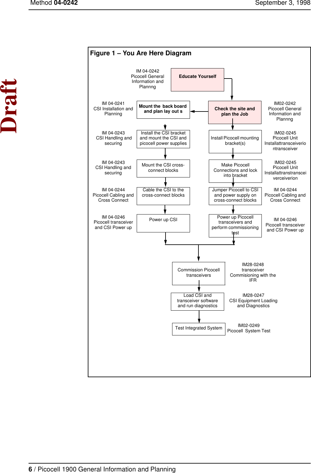
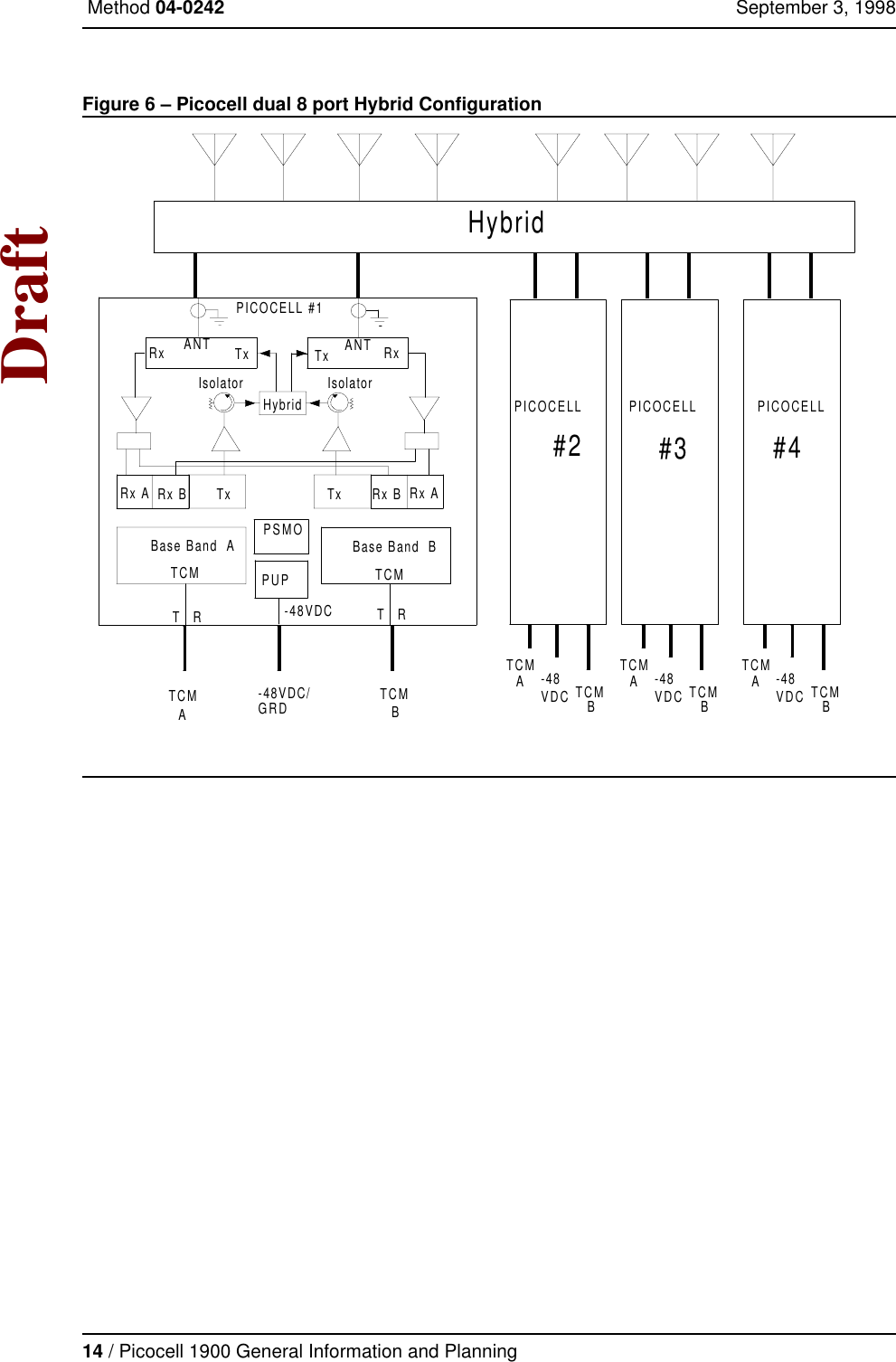
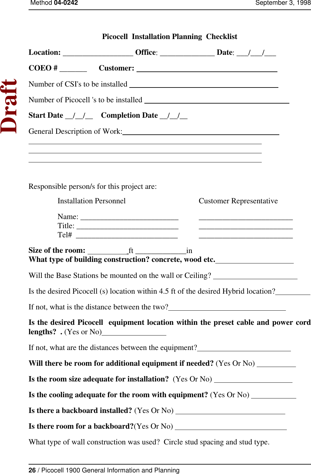
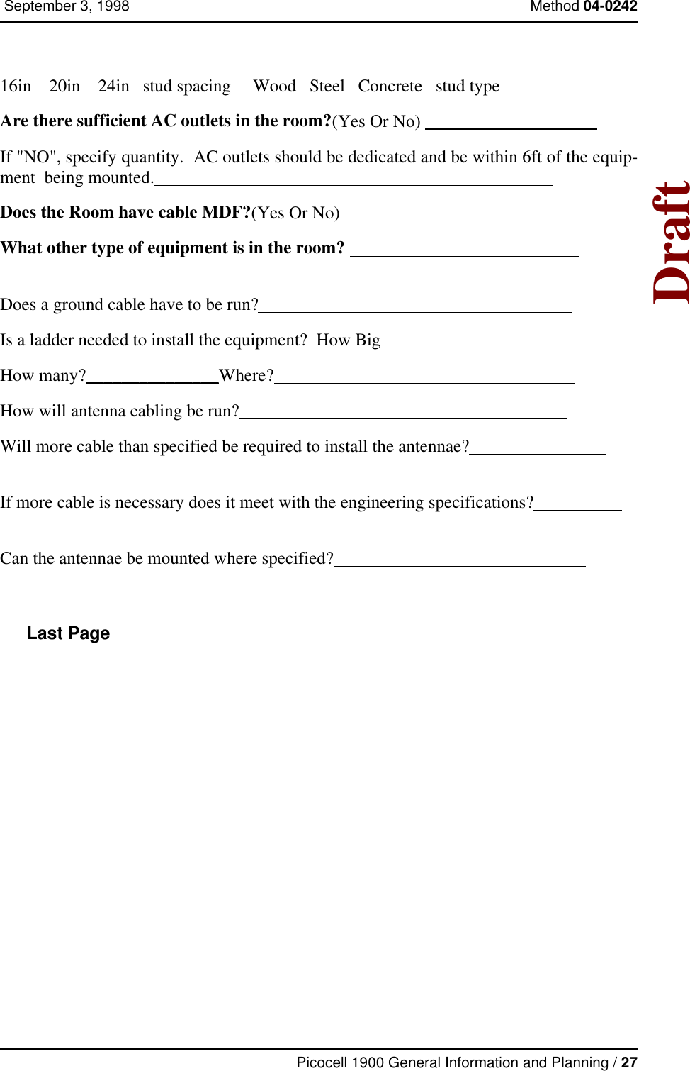
- 4. Picocell planning
- 5. Installation
- 6. Antenna
Users Manual Picocell planning