Avaya Canada NTMQ75AA User Manual 12 0152 antenna 1 02
Avaya Canada Corporation 12 0152 antenna 1 02
UserManual.wiki
>
Avaya Canada
>
NTMQ75AA User Manual
>
Antenna
Contents
1.
Users Manual Picocell planning
2.
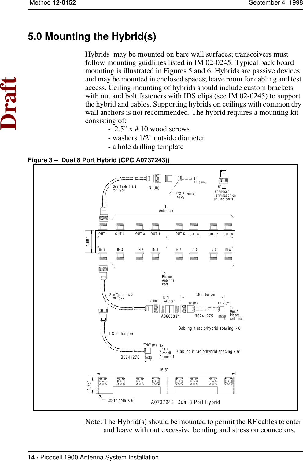
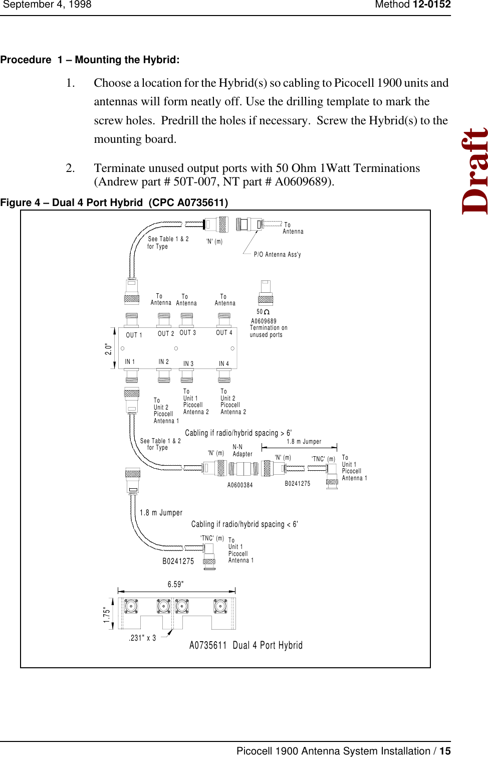
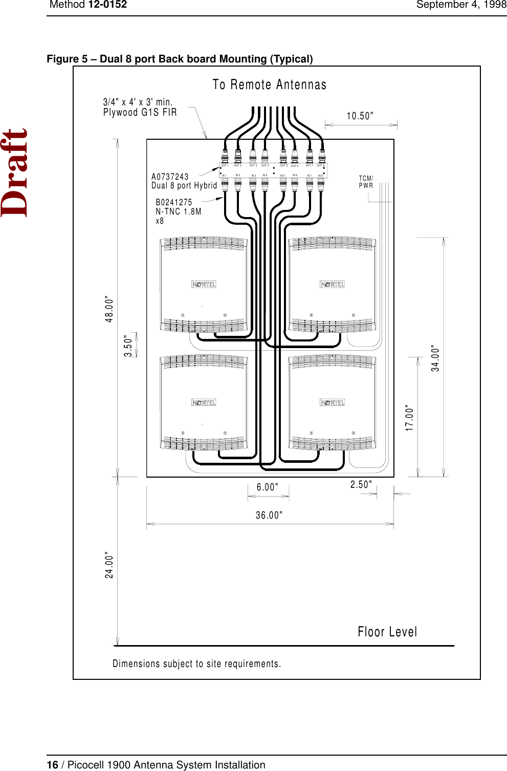
Users Manual installation
3.
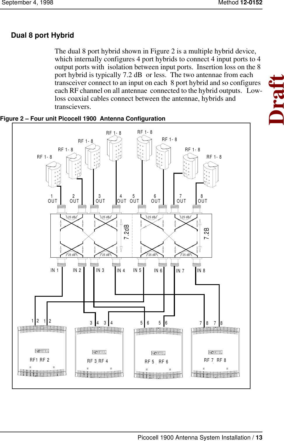
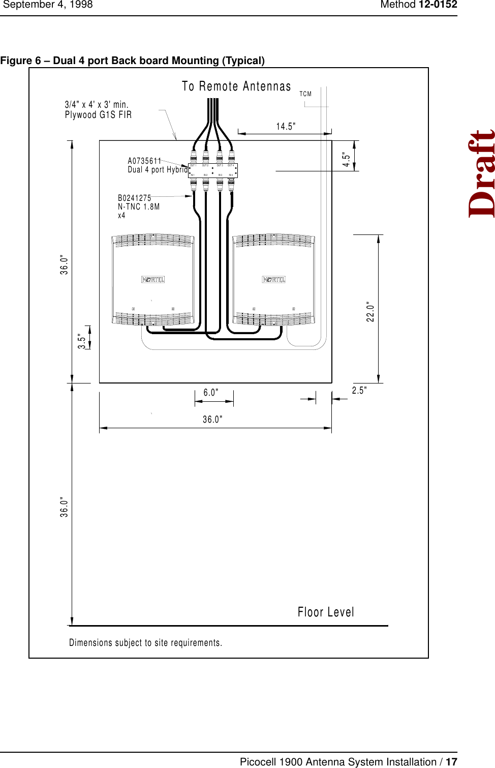
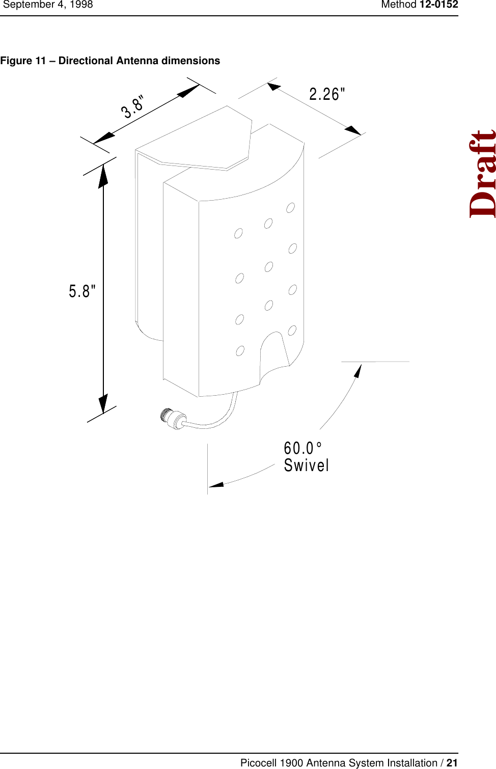
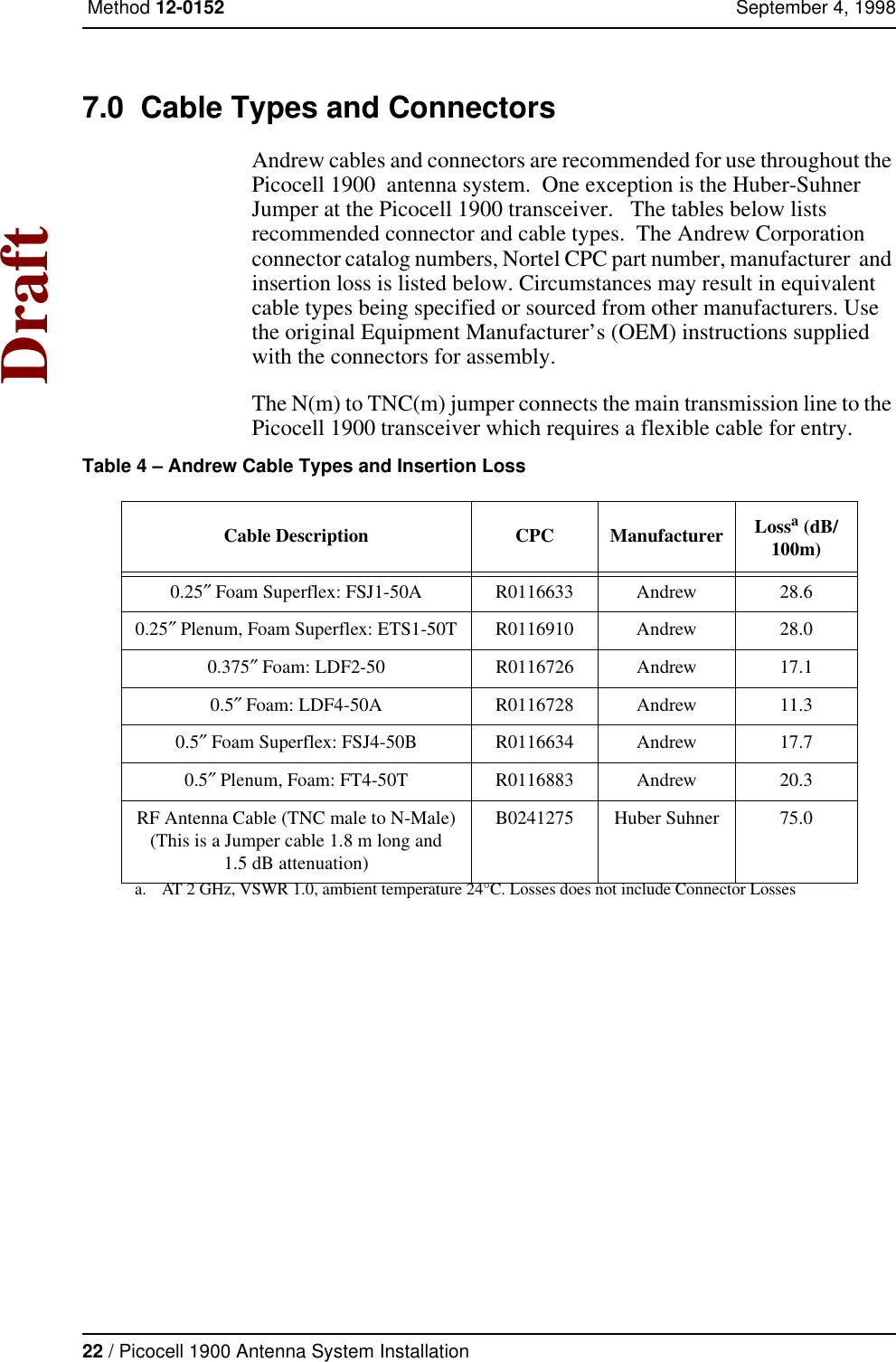
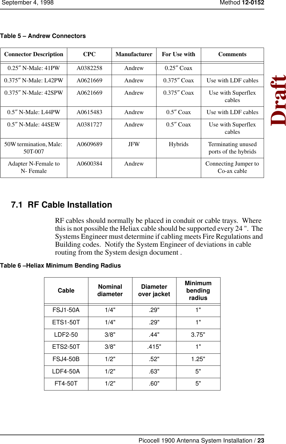
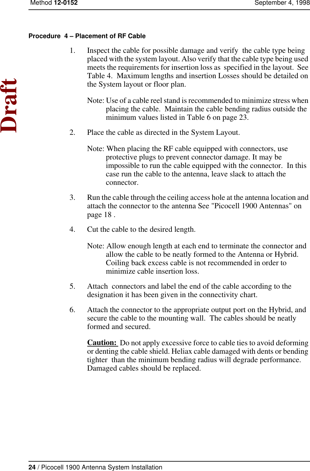
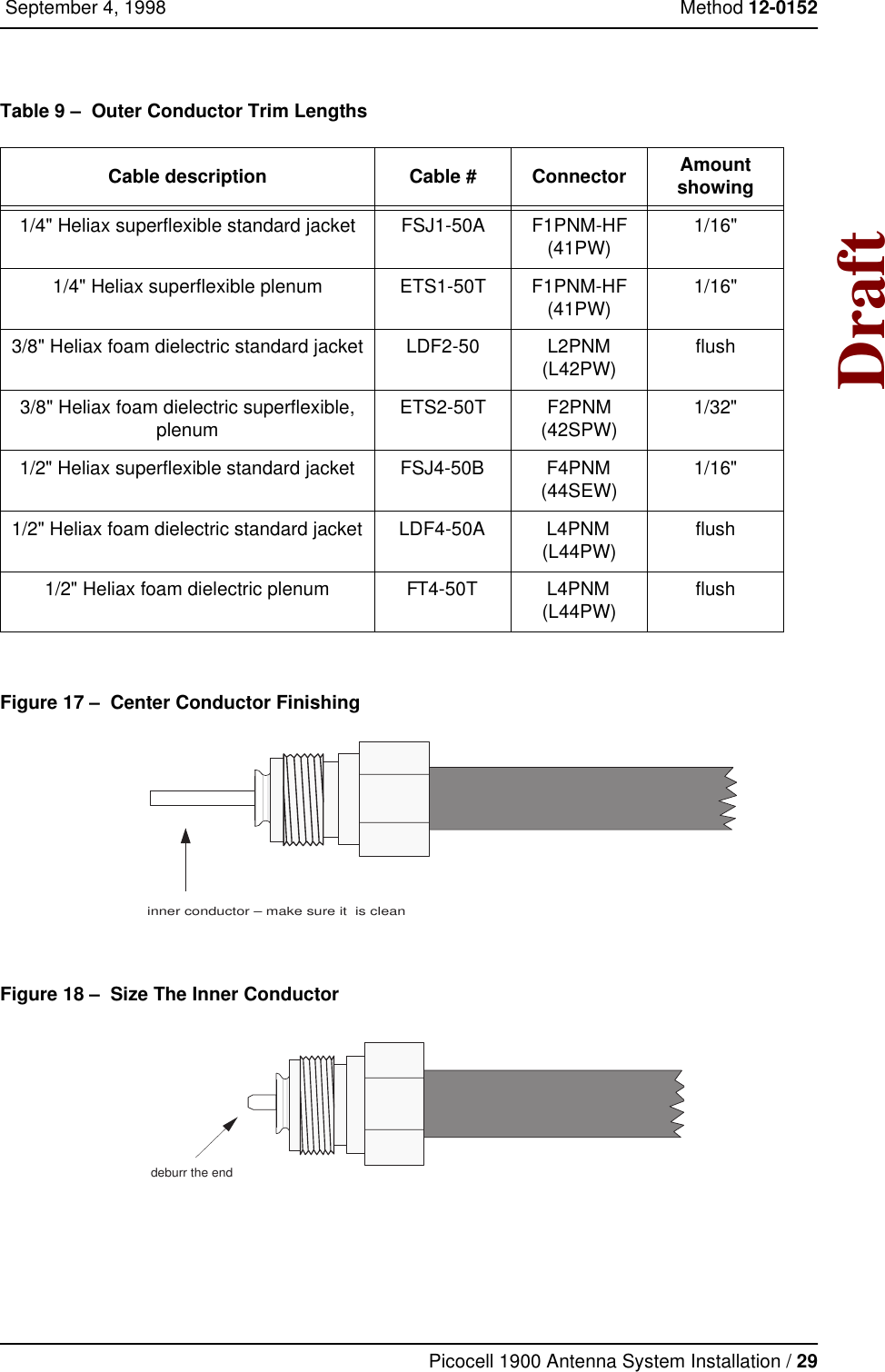
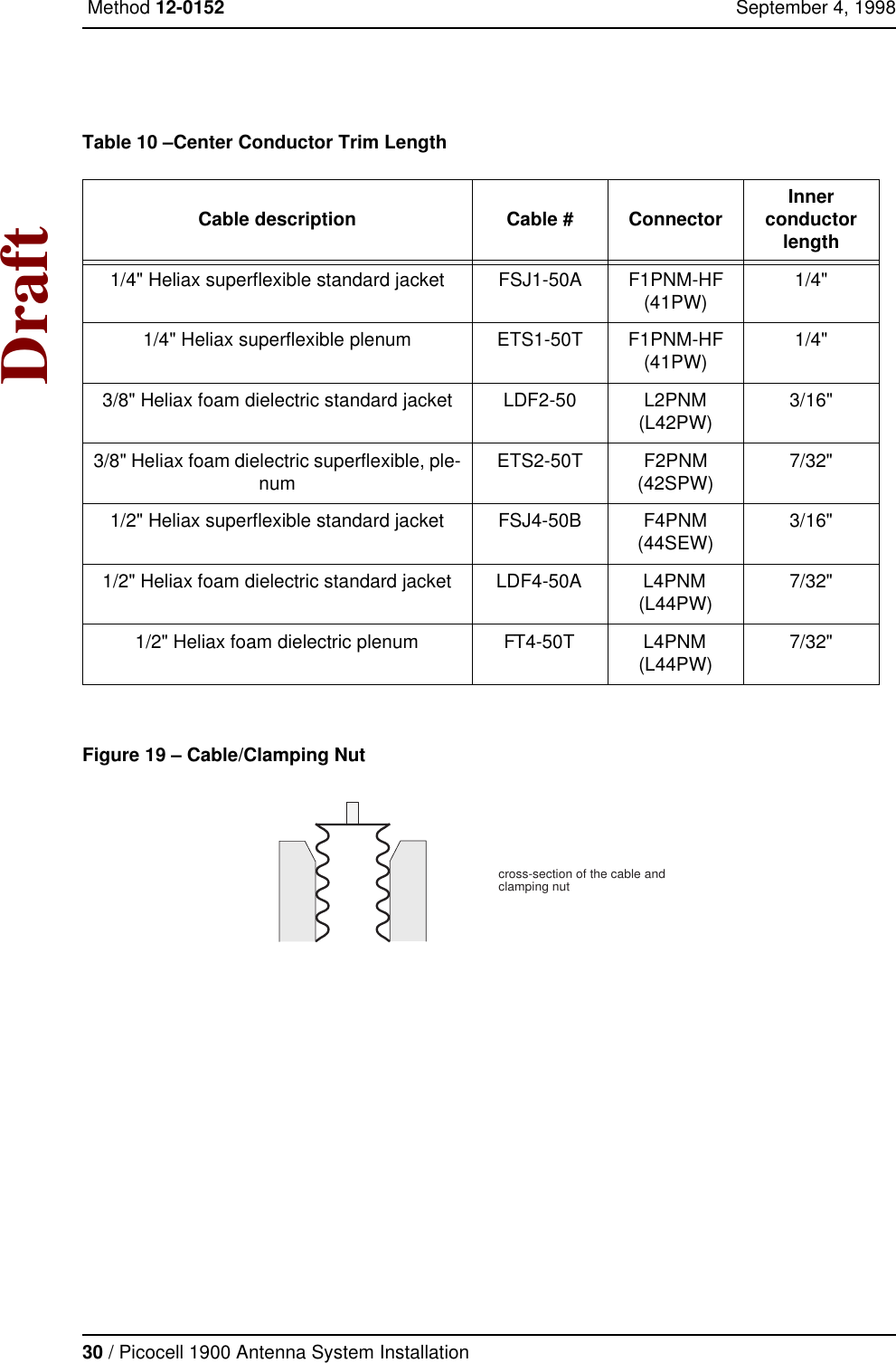
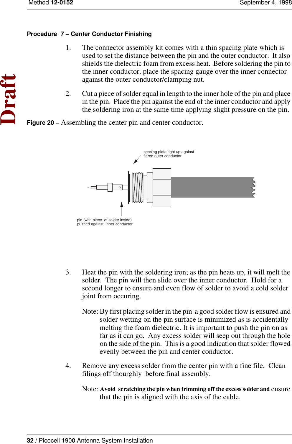
Users Manual antenna
4.
Picocell planning
5.
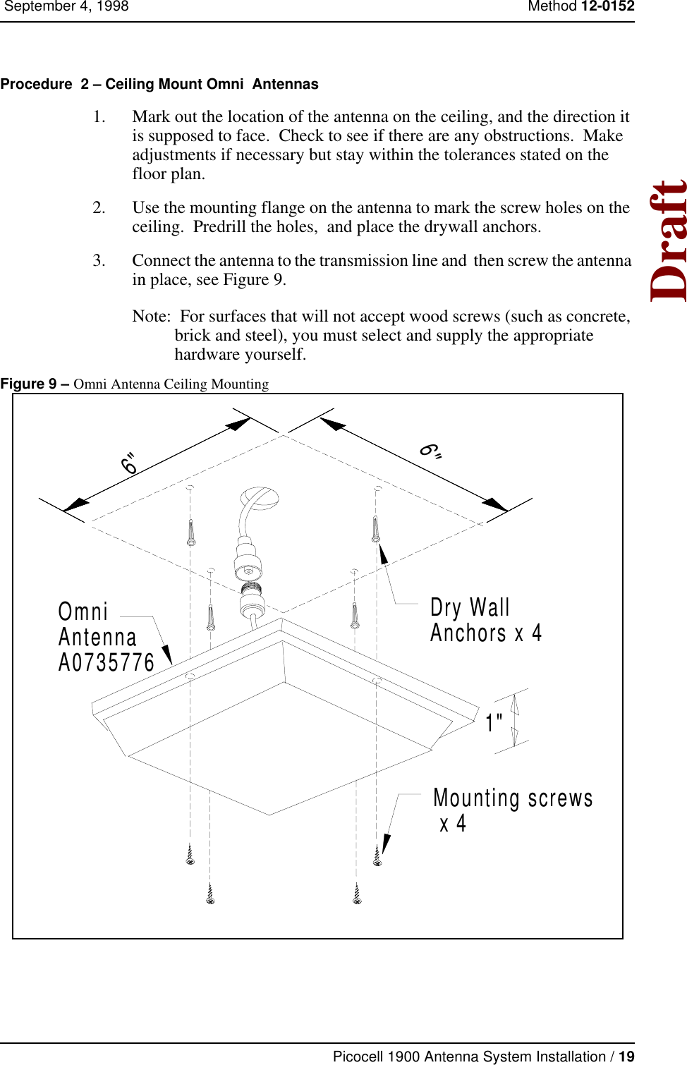
Installation
6.
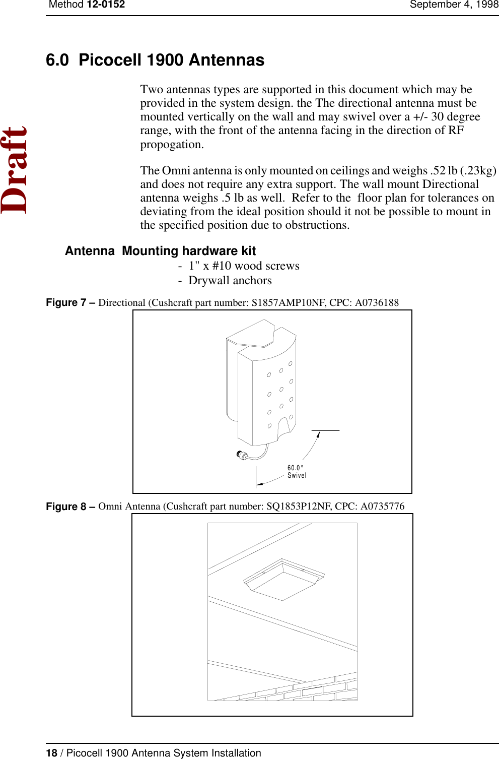
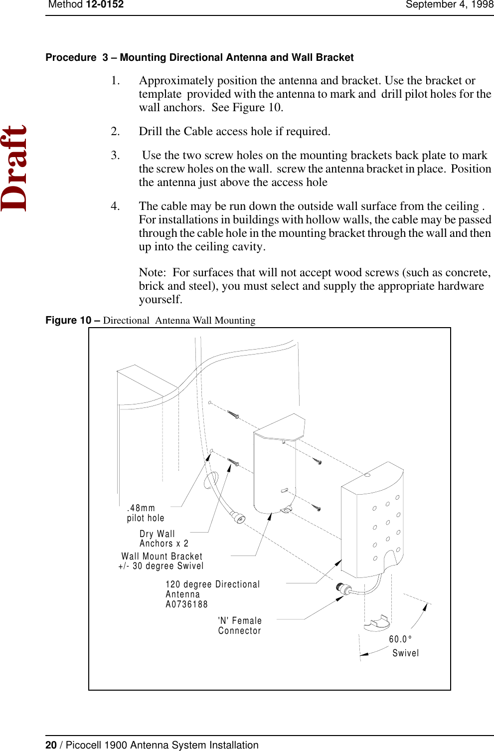
Antenna
Antenna
Navigation menu
Upload a User Manual
Namespaces
Wiki Guide
HTML
PDF
Info
Views
User Manual
Discussion / Help
Navigation